Embed Size (px)
Citation preview

CHAPTER 7
Transmission Media
We discussed many issues related to the physical layer in Chapters 3 through 6. In thischapter, we discuss transmission media. Transmission media are actually located belowthe physical layer and are directly controlled by the physical layer. You could say thattransmission media belong to layer zero. Figure 7.1 shows the position of transmissionmedia in relation to the physical layer.
Figure 7.1 Transmission medium and physical layer
Sender I Physical layer IL... Transmission medium
Cable or air
I Physical layer
.....JIReceiver
A transmission medium can be broadly defined as anything that can carry information from a source to a destination. For example, the transmission medium for twopeople having a dinner conversation is the air. The air can also be used to convey themessage in a smoke signal or semaphore. For a written message, the transmissionmedium might be a mail carrier, a truck, or an airplane.
In data communications the definition of the information and the transmissionmedium is more specific. The transmission medium is usually free space, metallic cable,or fiber-optic cable. The information is usually a signal that is the result of a conversionof data from another form.
The use of long-distance communication using electric signals started with theinvention of the telegraph by Morse in the 19th century. Communication by telegraphwas slow and dependent on a metallic medium.
Extending the range of the human voice became possible when the telephone wasinvented in 1869. Telephone communication at that time also needed a metallic mediumto carry the electric signals that were the result of a conversion from the human voice.
191

192 CHAPTER 7 1RANSMISSION MEDIA
The communication was, however, unreliable due to the poor quality of the wires. Thelines were often noisy and the technology was unsophisticated.
Wireless communication started in 1895 when Hertz was able to send highfrequency signals. Later, Marconi devised a method to send telegraph-type messagesover the Atlantic Ocean.
We have come a long way. Better metallic media have been invented (twistedpair and coaxial cables, for example). The use of optical fibers has increased the datarate incredibly. Free space (air, vacuum, and water) is used more efficiently, in partdue to the technologies (such as modulation and multiplexing) discussed in the previouschapters.
As discussed in Chapter 3, computers and other telecommunication devices usesignals to represent data. These signals are transmitted from one device to another in theform of electromagnetic energy, which is propagated through transmission media.
Electromagnetic energy, a combination of electric and magnetic fields vibrating inrelation to each other, includes power, radio waves, infrared light, visible light, ultravioletlight, and X, gamma, and cosmic rays. Each of these constitutes a portion of the electromagnetic spectrum. Not all portions of the spectrum are currently usable for telecommunications, however. The media to harness those that are usable are also limited to a fewtypes.
In telecommunications, transmission media can be divided into two broad categories: guided and unguided. Guided media include twisted-pair cable, coaxial cable, andfiber-optic cable. Unguided medium is free space. Figure 7.2 shows this taxonomy.
Figure 7.2 Classes of transmission media
7.1 GUIDED MEDIAGuided media, which are those that provide a conduit from one device to another,include twisted-pair cable, coaxial cable, and fiber-optic cable. A signal travelingalong any of these media is directed and contained by the physical limits of themedium. Twisted-pair and coaxial cable use metallic (copper) conductors that acceptand transport signals in the form of electric current. Optical fiber is a cable that acceptsand transports signals in the form of light.

SECTION 7.1 GUIDED MEDIA 193
Twisted-Pair Cable
A twisted pair consists of two conductors (normally copper), each with its own plasticinsulation, twisted together, as shown in Figure 7.3.
Figure 7.3 Twisted-pair cable
'""il""'<One of the wires is used to carry signals to the receiver, and the other is used only
as a ground reference. The receiver uses the difference between the two.In addition to the signal sent by the sender on one of the wires, interference (noise)
and crosstalk may affect both wires and create unwanted signals.If the two wires are parallel, the effect of these unwanted signals is not the same in
both wires because they are at different locations relative to the noise or crosstalk sources(e,g., one is closer and the other is farther). This results in a difference at the receiver. Bytwist,ing the pairs, a balance is maintained. For example, suppose in one twist, one wireis closer to the noise source and the other is farther; in the next twist, the reverse is true.Twisting makes it probable that both wires are equally affected by external influences(noise or crosstalk). This means that the receiver, which calculates the difference betweenthe two, receives no unwanted signals. The unwanted signals are mostly canceled out.From the above discussion, it is clear that the number of twists per unit of length(e.g., inch) has some effect on the quality of the cable.
Unshielded Versus Shielded Twisted-Pair Cable
The most common twisted-pair cable used in communications is referred to asunshielded twisted-pair (UTP). IBM has also produced a version of twisted-pair cablefor its use called shielded twisted-pair (STP). STP cable has a metal foil or braidedmesh covering that encases each pair of insulated conductors. Although metal casingimproves the quality of cable by preventing the penetration of noise or crosstalk, it isbulkier and more expensive. Figure 7.4 shows the difference between UTP and STP.Our discussion focuses primarily on UTP because STP is seldom used outside of IBM.
Categories
The Electronic Industries Association (EIA) has developed standards to classifyunshielded twisted-pair cable into seven categories. Categories are determined by cablequality, with 1 as the lowest and 7 as the highest. Each EIA category is suitable forspecific uses. Table 7. I shows these categories.
Connectors
The most common UTP connector is RJ45 (RJ stands for registered jack), as shownin Figure 7.5. The RJ45 is a keyed connector, meaning the connector can be inserted inonly one way.

194 CHAPTER 7 TRANSMISSION MEDIA
Figure 7.4 UTP and STP cables
Metal shield
Plastic cover
a.UTP
Plastic cover
b.STP
Table 7.1 Categories ofunshielded twisted-pair cables
Data RateCategory Specification (Mbps) Use
I Unshielded twisted-pair used in telephone < 0.1 Telephone
2 Unshielded twisted-pair originally used in 2 T-llinesT-lines
3 Improved CAT 2 used in LANs 10 LANs
4 Improved CAT 3 used in Token Ring networks 20 LANs
5 Cable wire is normally 24 AWG with a jacket 100 LANsand outside sheath
SE An extension to category 5 that includes 125 LANsextra features to minimize the crosstalk andelectromagnetic interference
6 A new category with matched components 200 LANscoming from the same manufacturer. Thecable must be tested at a 200-Mbps data rate.
7 Sometimes called SSTP (shielded screen 600 LANstwisted-pair). Each pair is individuallywrapped in a helical metallic foil followed bya metallic foil shield in addition to the outsidesheath. The shield decreases the effect ofcrosstalk: and increases the data rate.
Performance
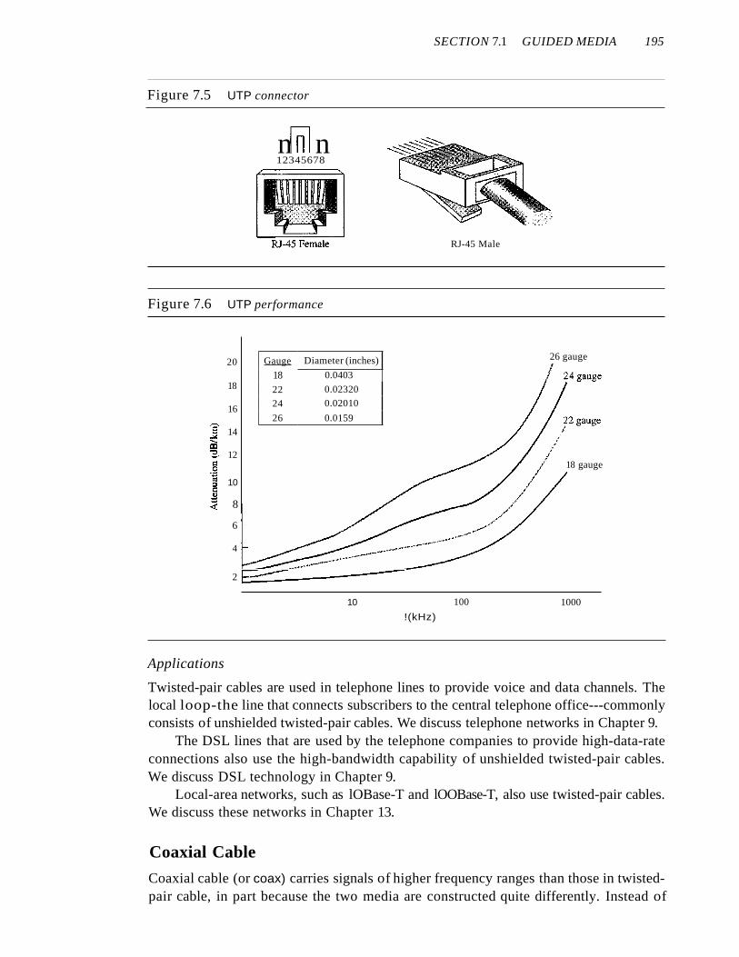
One way to measure the performance of twisted-pair cable is to compare attenuationversus frequency and distance. A twisted-pair cable can pass a wide range of frequencies.However, Figure 7.6 shows that with increasing frequency, the attenuation, measured indecibels per kilometer (dB/km), sharply increases with frequencies above 100 kHz. Notethat gauge is a measure of the thickness of the wire.
SECTION 7.1 GUIDED MEDIA 195
Figure 7.5 UTP connector
nrnl n12345678
RJ-45 Male
Figure 7.6 UTP performance
18 gauge
26 gaugeGauge Diameter (inches)
18 0.0403
22 0.02320
24 0.02010
26 0.0159
18
2 E::::::::..------4
20
16
]' 14
iIi::3- 12<::.g'" 10:I<::
"~ 8
6
10 100 1000
!(kHz)
Applications
Twisted-pair cables are used in telephone lines to provide voice and data channels. Thelocal loop-the line that connects subscribers to the central telephone office---commonlyconsists of unshielded twisted-pair cables. We discuss telephone networks in Chapter 9.
The DSL lines that are used by the telephone companies to provide high-data-rateconnections also use the high-bandwidth capability of unshielded twisted-pair cables.We discuss DSL technology in Chapter 9.
Local-area networks, such as lOBase-T and lOOBase-T, also use twisted-pair cables.We discuss these networks in Chapter 13.
Coaxial Cable
Coaxial cable (or coax) carries signals of higher frequency ranges than those in twistedpair cable, in part because the two media are constructed quite differently. Instead of

196 CHAPTER 7 TRANSMISSION MEDIA
having two wires, coax has a central core conductor of solid or stranded wire (usuallycopper) enclosed in an insulating sheath, which is, in turn, encased in an outer conductorof metal foil, braid, or a combination of the two. The outer metallic wrapping servesboth as a shield against noise and as the second conductor, which completes the circuit.This outer conductor is also enclosed in an insulating sheath, and the whole cable isprotected by a plastic cover (see Figure 7.7).
Figure 7.7 Coaxial cable
Insulator
Outer conductor(shield)
Coaxial Cable Standards
Coaxial cables are categorized by their radio government (RG) ratings. Each RG number denotes a unique set of physical specifications, including the wire gauge of theinner conductor, the thickness and type of the inner insulator, the construction of theshield, and the size and type of the outer casing. Each cable defined by an RG rating isadapted for a specialized function, as shown in Table 7.2.
Table 7.2 Categories ofcoaxial cables
Category Impedance Use
RG-59 75 n Cable TV
RG-58 50n Thin Ethernet
RG-ll 50n Thick Ethernet
Coaxial Cable Connectors
To connect coaxial cable to devices, we need coaxial connectors. The most commontype of connector used today is the Bayone-Neill-Concelman (BNe), connector.Figure 7.8 shows three popular types of these connectors: the BNC connector, theBNC T connector, and the BNC terminator.
The BNC connector is used to connect the end of the cable to a device, such as aTV set. The BNC T connector is used in Ethernet networks (see Chapter 13) to branchout to a connection to a computer or other device. The BNC terminator is used at theend of the cable to prevent the reflection of the signal.
SECTION 7.1 GUIDED MEDIA 11)7
----------------------------_. ------
Figure 7.8 BNC connectors
BNCTCable
t
BNC connector 50-aBNe terminator
Groundwire
---------------------------~---
Performance
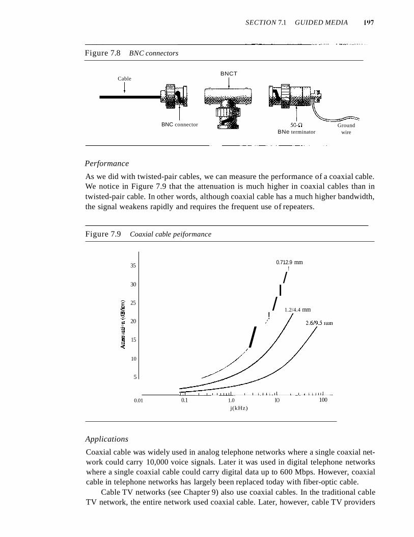
As we did with twisted-pair cables, we can measure the performance of a coaxial cable.We notice in Figure 7.9 that the attenuation is much higher in coaxial cables than intwisted-pair cable. In other words, although coaxial cable has a much higher bandwidth,the signal weakens rapidly and requires the frequent use of repeaters.
Figure 7.9 Coaxial cable peiformance
100IO
0.712.9 mm!
/I
/ 1.2/4.4 mm!
/
/
1.0
j(kHz)
0.1
35
30
a 25~a:l:2-
20.:0.~
;::l.: 15~~
10
5
0.01
Applications
Coaxial cable was widely used in analog telephone networks where a single coaxial network could carry 10,000 voice signals. Later it was used in digital telephone networkswhere a single coaxial cable could carry digital data up to 600 Mbps. However, coaxialcable in telephone networks has largely been replaced today with fiber-optic cable.
Cable TV networks (see Chapter 9) also use coaxial cables. In the traditional cableTV network, the entire network used coaxial cable. Later, however, cable TV providers

198 CHAPTER 7 TRANSMISSION MEDIA
replaced most of the media with fiber-optic cable; hybrid networks use coaxial cableonly at the network boundaries, near the consumer premises. Cable TV uses RG-59coaxial cable.
Another common application of coaxial cable is in traditional Ethernet LANs (seeChapter 13). Because of its high bandwidth, and consequently high data rate, coaxialcable was chosen for digital transmission in early Ethernet LANs. The 10Base-2, or ThinEthernet, uses RG-58 coaxial cable with BNe connectors to transmit data at 10 Mbpswith a range of 185 m. The lOBase5, or Thick Ethernet, uses RG-11 (thick coaxial cable)to transmit 10 Mbps with a range of 5000 m. Thick Ethernet has specialized connectors.
Fiber-Optic Cable
A fiber-optic cable is made of glass or plastic and transmits signals in the form of light.To understand optical fiber, we first need to explore several aspects of the nature of light.
Light travels in a straight line as long as it is moving through a single uniform substance. If a ray of light traveling through one substance suddenly enters another substance(of a different density), the ray changes direction. Figure 7.10 shows how a ray of lightchanges direction when going from a more dense to a less dense substance.
Figure 7.10 Bending of light ray
Lessdense
Moredense
Moredense
Lessdense
I> critical angle,reflection
Lessdense
III
More, Adensezj. ~
[ II
II
rI II
I = critical angle,refraction
/A
I
I < critical angle,refraction
As the figure shows, if the angle of incidence I (the arIgle the ray makes with theline perpendicular to the interface between the two substances) is less than the criticalangle, the ray refracts and moves closer to the surface. If the angle of incidence isequal to the critical angle, the light bends along the interface. If the angle is greater thanthe critical angle, the ray reflects (makes a turn) and travels again in the denser substance. Note that the critical angle is a property of the substance, and its value differsfrom one substance to another.
Optical fibers use reflection to guide light through a channel. A glass or plastic coreis surrounded by a cladding of less dense glass or plastic. The difference in density of thetwo materials must be such that a beam of light moving through the core is reflected offthe cladding instead of being refracted into it. See Figure 7.11.
Propagation Modes
Current technology supports two modes (multimode and single mode) for propagating lightalong optical channels, each requiring fiber with different physical characteristics. Multimode can be implemented in two forms: step-index or graded-index (see Figure 7.12).

SECTION 7.1 GUlDED MEDIA 199
Figure 7.11 Opticaljiber
Cladding
Sender
Figure 7.12 Propagation modes
Cladding
ReceiverL.-_....J
Multimode Multimode is so named because multiple beams from a light sourcemove through the core in different paths. How these beams move within the cabledepends on the structure ofthe core, as shown in Figure 7.13.
In multimode step-index fiber, the density of the core remains constant from thecenter to the edges. A beam of light moves through this constant density in a straightline until it reaches the interface of the core and the cladding. At the interface, there isan abrupt change due to a lower density; this alters the angle of the beam's motion. Theterm step index refers to the suddenness of this change, which contributes to the distortion of the signal as it passes through the fiber.
A second type of fiber, called multimode graded-index fiber, decreases this distortion of the signal through the cable. The word index here refers to the index of refraction.As we saw above, the index of refraction is related to density. A graded-index fiber,therefore, is one with varying densities. Density is highest at the center of the core anddecreases gradually to its lowest at the edge. Figure 7.13 shows the impact of this variable density on the propagation of light beams.
Single-Mode Single-mode uses step-index fiber and a highly focused source of lightthat limits beams to a small range of angles, all close to the horizontal. The singlemode fiber itself is manufactured with a much smaller diameter than that of multimodefiber, and with substantiallY lower density (index of refraction). The decrease in densityresults in a critical angle that is close enough to 90° to make the propagation of beamsalmost horizontal. In this case, propagation of different beams is almost identical, anddelays are negligible. All the beams arrive at the destination "together" and can berecombined with little distortion to the signal (see Figure 7.13).

200 CHAPTER 7 TRANSMISSION MEDIA
Figure 7.13 Modes
JlJ1Source
a. Multimode, step index
Destination
JlJ1Source Destination
b. Multimode, graded index
JlJ1Source
c. Single mode
Destination
Fiber Sizes
Optical fibers are defined by the ratio of the diameter of their core to the diameter oftheir cladding, both expressed in micrometers. The common sizes are shown in Table 7.3.Note that the last size listed is for single-mode only.
Table 7.3 Fiber types
Type Core(~) Cladding (Jlm) Mode
501125 50.0 125 Multimode, graded index
62.51125 62.5 125 Multimode, graded index
100/125 100.0 125 Multimode, graded index
7/125 7.0 125 Single mode
Cable Composition
Figure 7.14 shows the composition of a typical fiber-optic cable. The outer jacket is madeof either PVC or Teflon. Inside the jacket are Kevlar strands to strengthen the cable. Kevlaris a strong material used in the fabrication of bulletproof vests. Below the Kevlar is anotherplastic coating to cushion the fiber. The fiber is at the center of the cable, and it consists ofcladding and core.
Fiber-Optic Cable Connectors
There are three types of connectors for fiber-optic cables, as shown in Figure 7.15.

SECTION 7.1 GUIDED MEDIA 201
Figure 7.14 Fiber construction
Du Pont Kevlar/ for strength
Glass orplastic core
Figure 7.15 Fiber-optic cable connectors
SC connector ST connector
RX
TX
MT-RJ connector
The subscriber channel (SC) connector is used for cable TV. It uses a push/pulllocking system. The straight-tip (ST) connector is used for connecting cable tonetworking devices. It uses a bayonet locking system and is more reliable than SC.MT-RJ is a connector that is the same size as RJ45.
Performance
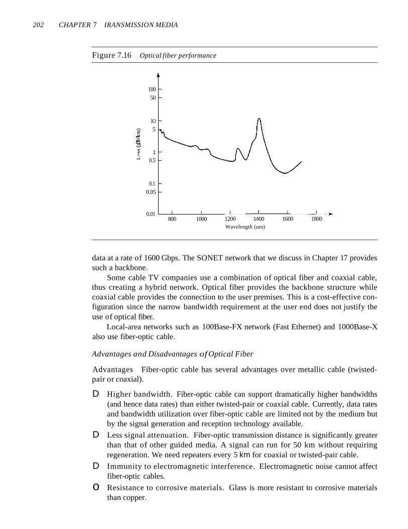
The plot of attenuation versus wavelength in Figure 7.16 shows a very interestingphenomenon in fiber-optic cable. Attenuation is flatter than in the case of twisted-paircable and coaxial cable. The performance is such that we need fewer (actually 10 timesless) repeaters when we use fiber-optic cable.
Applications
Fiber-optic cable is often found in backbone networks because its wide bandwidth iscost-effective. Today, with wavelength-division multiplexing (WDM), we can transfer
202 CHAPTER 7 IRANSMISSION MEDIA
Figure 7.16 Optical fiber performance
100
50
IO
~5
~
~00
1000
..l 0.5
0.1
0.05
0.01800 1000 1200 1400 1600 1800
Wavelength (urn)
data at a rate of 1600 Gbps. The SONET network that we discuss in Chapter 17 providessuch a backbone.
Some cable TV companies use a combination of optical fiber and coaxial cable,thus creating a hybrid network. Optical fiber provides the backbone structure whilecoaxial cable provides the connection to the user premises. This is a cost-effective configuration since the narrow bandwidth requirement at the user end does not justify theuse of optical fiber.
Local-area networks such as 100Base-FX network (Fast Ethernet) and 1000Base-Xalso use fiber-optic cable.
Advantages and Disadvantages of Optical Fiber
Advantages Fiber-optic cable has several advantages over metallic cable (twistedpair or coaxial).
D Higher bandwidth. Fiber-optic cable can support dramatically higher bandwidths(and hence data rates) than either twisted-pair or coaxial cable. Currently, data ratesand bandwidth utilization over fiber-optic cable are limited not by the medium butby the signal generation and reception technology available.
D Less signal attenuation. Fiber-optic transmission distance is significantly greaterthan that of other guided media. A signal can run for 50 km without requiringregeneration. We need repeaters every 5 km for coaxial or twisted-pair cable.
D Immunity to electromagnetic interference. Electromagnetic noise cannot affectfiber-optic cables.
o Resistance to corrosive materials. Glass is more resistant to corrosive materialsthan copper.

SECTION 7.2 UNGUIDED MEDIA: WIRELESS 203
o Light weight. Fiber-optic cables are much lighter than copper cables.
o Greater immunity to tapping. Fiber-optic cables are more immune to tapping thancopper cables. Copper cables create antenna effects that can easily be tapped.
Disadvantages There are some disadvantages in the use of optical fiber.
o Installation and maintenance. Fiber-optic cable is a relatively new technology. Itsinstallation and maintenance require expertise that is not yet available everywhere.
o Unidirectional light propagation. Propagation of light is unidirectional. If weneed bidirectional communication, two fibers are needed.
o Cost. The cable and the interfaces are relatively more expensive than those of otherguided media. If the demand for bandwidth is not high, often the use of optical fibercannot be justified.
7.2 UNGUIDED MEDIA: WIRELESSUnguided media transport electromagnetic waves without using a physical conductor.This type of communication is often referred to as wireless communication. Signalsare normally broadcast through free space and thus are available to anyone who has adevice capable of receiving them.
Figure 7.17 shows the part of the electromagnetic spectrum, ranging from 3 kHz to900 THz, used for wireless communication.
Figure 7.17 Electromagnetic spectrumfor wireless communication
3kHz
Radio wave and microwave
300 400 900GHz THz THz
Unguided signals can travel from the source to destination in several ways: groundpropagation, sky propagation, and line-of-sight propagation, as shown in Figure 7.18.
In ground propagation, radio waves travel through the lowest portion of theatmosphere, hugging the earth. These low-frequency signals emanate in all directionsfrom the transmitting antenna and follow the curvature of the planet. Distance dependson the amount of power in the signal: The greater the power, the greater the distance. Insky propagation, higher-frequency radio waves radiate upward into the ionosphere(the layer of atmosphere where particles exist as ions) where they are reflected back toearth. This type of transmission allows for greater distances with lower output power.In line-or-sight propagation, very high-frequency signals are transmitted in straightlines directly from antenna to antenna. Antennas must be directional, facing each other,

204 CHAPTER 7 TRANSMISSION MEDIA
Figure 7.18 Propagation methods
Ionosphere
Ground propagation(below 2 MHz)
Ionosphere
Sky propagation(2-30 MHz)
Ionosphere
Line-af-sight propagation(above 30 MHz)
and either tall enough or close enough together not to be affected by the curvature ofthe earth. Line-of-sight propagation is tricky because radio transmissions cannot becompletely focused.
The section of the electromagnetic spectrum defined as radio waves and microwavesis divided into eight ranges, called bands, each regulated by government authorities.These bands are rated from very low frequency (VLF) to extremely highfrequency (EHF).Table 7.4 lists these bands, their ranges, propagation methods, and some applications.
Table 7.4 Bands
Band Range Propagation Application
VLF (very low frequency) 3-30 kHz Ground Long-range radionavigation
LF (low frequency) 30-300 kHz Ground Radio beacons andnavigational locators
MF (middle frequency) 300 kHz-3 MHz Sky AM radio
HF (high frequency) 3-30 MHz Sky Citizens band (CB),shipiaircraftcommunication
VHF (very high frequency) 30-300 MHz Sky and VHF TV, FM radioline-of-sight
UHF (ultrahigh frequency) 300 MHz-3 GHz Line-of-sight UHF TV, cellular phones,paging, satellite
SHF (superhigh frequency) 3-30 GHz Line-of-sight Satellite communication
EHF (extremely high 30-300 GHz Line-of-sight Radar, satellitefrequency)
We can divide wireless transmission into three broad groups: radio waves, microwaves, and infrared waves. See Figure 7.19.

SECTION 7.2 UNGUIDED MEDIA: WIRELESS 205
Figure 7.19 Wireless transmission waves
Radio Waves
Although there is no clear-cut demarcation between radio waves and microwaves, electromagnetic waves ranging in frequencies between 3 kHz and 1 GHz are normally calledradio waves; waves ranging in frequencies between 1 and 300 GHz are called microwaves. However, the behavior of the waves, rather than the frequencies, is a bettercriterion for classification.
Radio waves, for the most part, are omnidirectional. When an antenna transmitsradio waves, they are propagated in all directions. This means that the sending andreceiving antennas do not have to be aligned. A sending antenna sends waves that canbe received by any receiving antenna. The omnidirectional property has a disadvantage,too. The radio waves transmitted by one antenna are susceptible to interference byanother antenna that may send signals using the same frequency or band.
Radio waves, particularly those waves that propagate in the sky mode, can travellong distances. This makes radio waves a good candidate for long-distance broadcasting such as AM radio.
Radio waves, particularly those of low and medium frequencies, can penetrate walls.This characteristic can be both an advantage and a disadvantage. It is an advantagebecause, for example, an AM radio can receive signals inside a building. It is a disadvantage because we cannot isolate a communication to just inside or outside a building. Theradio wave band is relatively narrow, just under 1 GHz, compared to the microwaveband. When this band is divided into subbands, the subbands are also narrow, leading to alow data rate for digital communications.
Almost the entire band is regulated by authorities (e.g., the FCC in the UnitedStates). Using any part of the band requires permission from the authorities.
Omnidirectional Antenna
Radio waves use omnidirectional antennas that send out signals in all directions.Based on the wavelength, strength, and the purpose of transmission, we can have several types of antennas. Figure 7.20 shows an omnidirectional antenna.
Applications
The omnidirectional characteristics of radio waves make them useful for multicasting,in which there is one sender but many receivers. AM and FM radio, television, maritime radio, cordless phones, and paging are examples of multicasting.

206 CHAPTER 7 TRANSMISSION MEDIA
Figure 7.20 Omnidirectional antenna
Radio waves are used for multicast communications,such as radio and television, and paging systems.
Microwaves
Electromagnetic waves having frequencies between I and 300 GHz are called microwaves.
Microwaves are unidirectional. When an antenna transmits microwave waves, theycan be narrowly focused. This means that the sending and receiving antennas need tobe aligned. The unidirectional property has an obvious advantage. A pair of antennascan be aligned without interfering with another pair of aligned antennas. The followingdescribes some characteristics of microwave propagation:
o Microwave propagation is line-of-sight. Since the towers with the mounted antennasneed to be in direct sight of each other, towers that are far apart need to be very tall.The curvature of the earth as well as other blocking obstacles do not allow two shorttowers to communicate by using microwaves. Repeaters are often needed for longdistance communication.
o Very high-frequency microwaves cannot penetrate walls. This characteristic can bea disadvantage if receivers are inside buildings.
o The microwave band is relatively wide, almost 299 GHz. Therefore wider subbandscan be assigned, and a high data rate is possible
o Use of certain portions of the band requires permission from authorities.
Unidirectional Antenna
Microwaves need unidirectional antennas that send out signals in one direction. Twotypes of antennas are used for microwave communications: the parabolic dish and thehom (see Figure 7.21).
A parabolic dish antenna is based on the geometry of a parabola: Every lineparallel to the line of symmetry (line of sight) reflects off the curve at angles such thatall the lines intersect in a common point called the focus. The parabolic dish works as a

SECTION 7.2 UNGUIDED MEDIA: WIRELESS 207
Figure 7.21 Unidirectional antennas
Focus ~,,*=:::I
a. Dish antenna b. Horn antenna
funnel, catching a wide range of waves and directing them to a common point. Inthis way, more of the signal is recovered than would be possible with a single-pointreceiver.
Outgoing transmissions are broadcast through a horn aimed at the dish. The microwaves hit the dish and are deflected outward in a reversal of the receipt path.
A horn antenna looks like a gigantic scoop. Outgoing transmissions are broadcastup a stem (resembling a handle) and deflected outward in a series of narrow parallelbeams by the curved head. Received transmissions are collected by the scooped shape ofthe horn, in a manner similar to the parabolic dish, and are deflected down into the stem.
Applications
Microwaves, due to their unidirectional properties, are very useful when unicast(one-to-one) communication is needed between the sender and the receiver. They areused in cellular phones (Chapter 16), satellite networks (Chapter 16), and wireless LANs(Chapter 14).
Microwaves are used for unicast communication such as cellular telephones,satellite networks, and wireless LANs.
Infrared
Infrared waves, with frequencies from 300 GHz to 400 THz (wavelengths from 1 mmto 770 nm), can be used for short-range communication. Infrared waves, having highfrequencies, cannot penetrate walls. This advantageous characteristic prevents interference between one system and another; a short-range communication system in one roomcannot be affected by another system in the next room. When we use our infrared remotecontrol, we do not interfere with the use of the remote by our neighbors. However, thissame characteristic makes infrared signals useless for long-range communication. Inaddition, we cannot use infrared waves outside a building because the sun's rays containinfrared waves that can interfere with the communication.

208 CHAPTER 7 TRANSMISSION MEDIA
Applications
The infrared band, almost 400 THz, has an excellent potential for data transmission.Such a wide bandwidth can be used to transmit digital data with a very high data rate.The Infrared Data Association (IrDA), an association for sponsoring the use of infraredwaves, has established standards for using these signals for communication betweendevices such as keyboards, mice, PCs, and printers. For example, some manufacturersprovide a special port called the IrDA port that allows a wireless keyboard to communicate with a PC. The standard originally defined a data rate of 75 kbps for a distanceup to 8 m. The recent standard defines a data rate of 4 Mbps.
Infrared signals defined by IrDA transmit through line of sight; the IrDA port onthe keyboard needs to point to the PC for transmission to occur.
Infrared signals can be used for short-range communicationin a closed area using line-of-sight propagation.
7.3 RECOMMENDED READINGFor more details about subjects discussed in this chapter, we recommend the followingbooks. The items in brackets [...] refer to the reference list at the end of the text.
Books
Transmission media is discussed in Section 3.8 of [GW04], Chapter 4 of [Sta04], Section 2.2 and 2.3 of [Tan03]. [SSS05] gives a full coverage of transmission media.
7.4 KEY TERMSangle of incidence
Bayone-Neil-Concelman (BNC)connector
cladding
coaxial cable
core
critical angle
electromagnetic spectrum
fiber-optic cable
gauge
ground propagation
guided media
horn antenna
infrared wave
IrDA port
line-of-sight propagation
microwave
MT-RJ
multimode graded-index fiber
multimode step-index fiber
omnidirectional antenna
optical fiber
parabolic dish antenna
Radio Government (RG) number
radio wave
reflection
refraction
RJ45

shielded twisted-pair (STP)
single-mode fiber
sky propagation
straight-tip (ST) connector
subscriber channel (SC) connector
transmission medium
SECTION 7.6 PRACTICE SET 209
twisted-pair cable
unguided medium
unidirectional antenna
unshielded twisted-pair(UTP)
wireless communication
7.5 SUMMARYo Transmission media lie below the physical layer.
D A guided medium provides a physical conduit from one device to another. Twistedpair cable, coaxial cable, and optical fiber are the most popular types of guidedmedia.
D Twisted-pair cable consists of two insulated copper wires twisted together. Twistedpair cable is used for voice and data communications.
D Coaxial cable consists of a central conductor and a shield. Coaxial cable can carrysignals of higher frequency ranges than twisted-pair cable. Coaxial cable is used incable TV networks and traditional Ethernet LANs.
o Fiber-optic cables are composed of a glass or plastic inner core surrounded bycladding, all encased in an outside jacket. Fiber-optic cables carry data signals inthe form of light. The signal is propagated along the inner core by reflection. Fiberoptic transmission is becoming increasingly popular due to its noise resistance, lowattenuation, and high-bandwidth capabilities. Fiber-optic cable is used in backbonenetworks, cable TV networks, and Fast Ethernet networks.
D Unguided media (free space) transport electromagnetic waves without the use of aphysical conductor.
o Wireless data are transmitted through ground propagation, sky propagation, and lineof-sight propagation.Wireless waves can be classified as radio waves, microwaves, orinfrared waves. Radio waves are omnidirectional; microwaves are unidirectional.Microwaves are used for cellular phone, satellite, and wireless LAN communications.
D Infrared waves are used for short-range communications such as those between aPC and a peripheral device. It can also be used for indoor LANs.
7.6 PRACTICE SET
Review Questions1. What is the position of the transmission media in the OSI or the Internet model?
2. Name the two major categories of transmission media.
3. How do guided media differ from unguided media?
4. What are the three major classes of guided media?
5. What is the significance of the twisting in twisted-pair cable?

210 CHAPTER 7 TRANSMISSION MEDIA
6. What is refraction? What is reflection?
7. What is the purpose of cladding in an optical fiber?
8. Name the advantages of optical fiber over twisted-pair and coaxial cable.
9. How does sky propagation differ from line-of-sight propagation?
10. What is the difference between omnidirectional waves and unidirectional waves?
Exercises
11. Using Figure 7.6, tabulate the attenuation (in dB) of a 18-gauge UTP for the indicatedfrequencies and distances.
Table 7.5 Attenuation/or I8-gauge UTP
Distance dB at 1 KHz dRat 10KHz dB at 100 KHz
1 Krn
lOKm
15 Krn
20Km
12. Use the result of Exercise 11 to infer that the bandwidth of a UTP cable decreaseswith an increase in distance.
13. If the power at the beginning of a 1 KIn 18-gauge UTP is 200 mw, what is thepower at the end for frequencies 1 KHz, 10 KHz, and 100 KHz? Use the result ofExercise 11.
14. Using Figure 7.9, tabulate the attenuation (in dB) of a 2.6/9.5 mm coaxial cable forthe indicated frequencies and distances.
Table 7.6 Attenuation/or 2.6/9.5 mm coaxial cable
Distance dB at 1 KHz dB at 10 KHz dB at 100KHz
1 Km
lOKrn
15Km
20Km
15. Use the result of Exercise 14 to infer that the bandwidth of a coaxial cabledecreases with the increase in distance.
16. If the power at the beginning of a 1 KIn 2.6/9.5 mm coaxial cable is 200 mw, whatis the power at the end for frequencies 1 KHz, 10KHz, and 100 KHz? Use theresult of Exercise 14.
17. Calculate the bandwidth of the light for the following wavelength ranges (assume apropagation speed of 2 x 10⁸ m):
a. 1000 to 1200 nm
b. 1000 to 1400 nm

SECTION 7.6 PRACTICE SET 211
18. The horizontal axes in Figure 7.6 and 7.9 represent frequencies. The horizontalaxis in Figure 7.16 represents wavelength. Can you explain the reason? lfthe propagation speed in an optical fiber is 2 x 10⁸ ill, can you change the units in the horizontal axis to frequency? Should the vertical-axis units be changed too? Should thecurve be changed too?
19. Using Figure 7.16, tabulate the attenuation (in dB) of an optical fiber for the indicatedwavelength and distances.
Table 7.7 Attenuation for optical fiber
Distance dB at 800 nm dB at 1000 nm dB at 1200nm
1 Km
lOKm
15Km
20Km
20. A light signal is travelling through a fiber. What is the delay in the signal if thelength of the fiber-optic cable is 10 m, 100 m, and 1 Km (assume a propagationspeed of 2 x 10⁸ ill)?
21. A beam oflight moves from one medium to another medium with less density. Thecritical angle is 60°. Do we have refraction or reflection for each of the followingincident angles? Show the bending of the light ray in each case.
a. 40°
b. 60°
c. 800


![APPARATUS FOR UNSHIELDED TWISTED PAIR (UTP) CABLES ... · 1.3 Unshielded twisted pair cable [2] Nowadays most networks are constructed using unshielded twisted pair cable (UTP). As](https://img.dokumen.tips/doc/110x75/5f9fd0db5f2ede190b2c6418/apparatus-for-unshielded-twisted-pair-utp-cables-13-unshielded-twisted-pair.jpg)