Embed Size (px)
Citation preview

Lab2: A self balancing platform v.9b 1
Laboratory 2
A self balancing platform

Lab2: A self balancing platform v.9b 2
Objectives
1. Objectives To lean how to interface a direct current (DC) output
sensor to an microcontroller To learn how to implement a
Proportional–Integral–Derivative PID feed back control system.
2. Aim To develop a self-balancing platform using an
embedded system. Reference:
http://www.cse.cuhk.edu.hk/%7Ekhwong/ceg3480/PID_DC_motor_Control08.ppt

Lab2: A self balancing platform v.9b 3
PWM generator
control method:PID (proportional-integral-derivative) control
Required position=0
Left_pwm
+
- tmpl
Integral control
I* (deltal) dt
Proportional control
=P*(deltal)
Derivative control
D*d(deltal)/dt ;
sum
error terme=0-tmpl=deltal
PositionSensor(tmpl)
0

Lab2: A self balancing platform v.9b 4
The experimental setup
video

Lab2: A self balancing platform v.9b 5
Fig. 1b.Block Diagram of the Self-balancing platform
Lab2: A self balancing platform v.9b 6
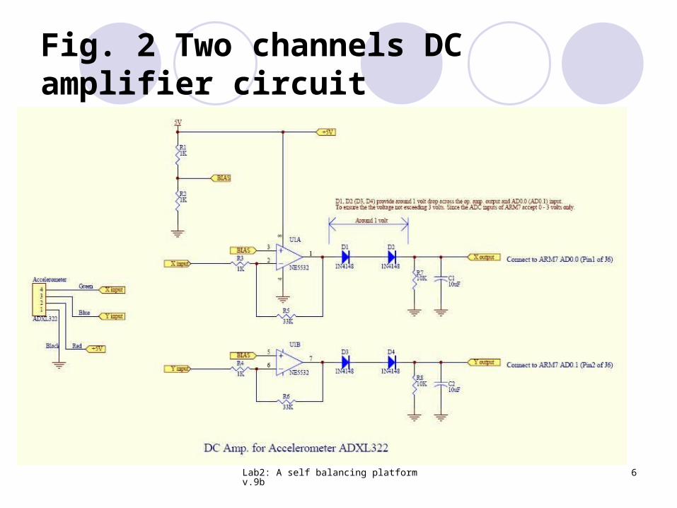
Fig. 2 Two channels DC amplifier circuit

Lab2: A self balancing platform v.9b 7
Fig. 3 (a) Top View of the Accelerometer , (b) the sensor attached to the bottom of the platform
x-axis
y-axis
In the arm mcuwe set 15000 = read_sensor(1.5V);

Lab2: A self balancing platform v.9b 8
Special techniques
MIDL is the mid set point value for X-axis Use integer “int” to simulate floating point
Multiply the value by x and divide it by x afterwards, (e.g. x=200 in our example)
tmpl is the tilt position measurement e=deltal = (tmpl - (MIDL+200)) / 200; Derivative is d[e(t)] / dt = e (current ) – e (previous)
diffl = deltal – lastl; Integration is e dt = e (current) + e (previous)
accul += deltal/200; //arbitrary set to divide by 200, Dead-band (see next page)

Lab2: A self balancing platform v.9b 9
Dead band
Dead-band : A Dead-band (sometimes called a neutral zone) is an area of a signal range or band where no action occurs : only enable motor when tile angle outside +/- degrees (=0.1 degrees). http://en.wikipedia.org/wiki/Dead-band
Dead-band
Lab2: A self balancing platform v.9b 10
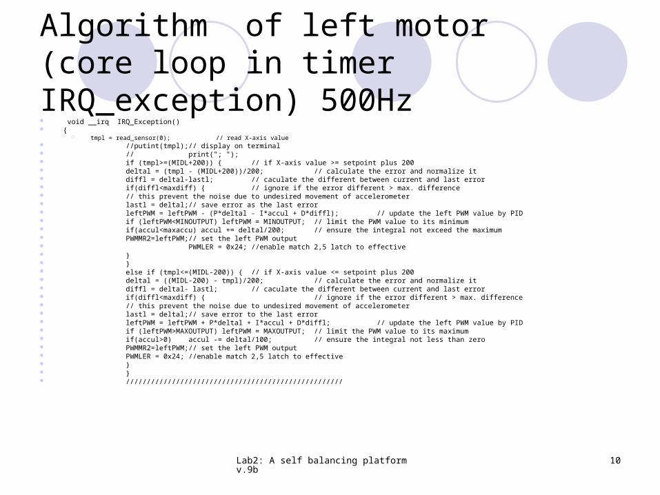
Algorithm of left motor (core loop in timer IRQ_exception) 500Hz void __irq IRQ_Exception() {
tmpl = read_sensor(0); // read X-axis value //putint(tmpl); // display on terminal // print("; "); if (tmpl>=(MIDL+200)) { // if X-axis value >= setpoint plus 200 deltal = (tmpl - (MIDL+200))/200; // calculate the error and normalize it diffl = deltal-lastl; // caculate the different between current and last error if(diffl<maxdiff) { // ignore if the error different > max. difference
// this prevent the noise due to undesired movement of accelerometer lastl = deltal; // save error as the last error leftPWM = leftPWM - (P*deltal - I*accul + D*diffl); // update the left PWM value by PID if (leftPWM<MINOUTPUT) leftPWM = MINOUTPUT; // limit the PWM value to its minimum if(accul<maxaccu) accul += deltal/200; // ensure the integral not exceed the maximum PWMMR2=leftPWM; // set the left PWM output PWMLER = 0x24; //enable match 2,5 latch to effective } } else if (tmpl<=(MIDL-200)) { // if X-axis value <= setpoint plus 200 deltal = ((MIDL-200) - tmpl)/200; // calculate the error and normalize it diffl = deltal- lastl; // caculate the different between current and last error if(diffl<maxdiff) { // ignore if the error different > max. difference
// this prevent the noise due to undesired movement of accelerometer lastl = deltal;
// save error to the last error leftPWM = leftPWM + P*deltal + I*accul + D*diffl; // update the left PWM value by PID if (leftPWM>MAXOUTPUT) leftPWM = MAXOUTPUT; // limit the PWM value to its maximum if(accul>0) accul -= deltal/100;
// ensure the integral not less than zero PWMMR2=leftPWM;
// set the left PWM output PWMLER = 0x24; //enable match 2,5 latch to effective } } ////////////////////////////////////////////////////

Lab2: A self balancing platform v.9b 11
if (tmpl>=(MIDL+200))Tile position > degrees (outside dead band) void __irq IRQ_Exception() //running at 500Hz, set by timer { tmpl = read_sensor(0); // read X-axis value //putint(tmpl); if (tmpl>=(MIDL+200)) {// if X-axis value >= setpoint plus 200 deltal = (tmpl - (MIDL+200))/200; // cal.error and normalize it diffl = deltal-lastl; // cal. different between current and last error if(diffl<maxdiff) // ignore if the error different > max. difference {//prevents noise from undesired accelerometer movement lastl =
deltal; // save error as the last error leftPWM = leftPWM - (P*deltal - I*accul +D*diffl);//updatePWM if (leftPWM<MINOUTPUT) leftPWM = MINOUTPUT;// limit PWM to its min. if(accul<maxaccu) //make sure accul cannot grow too big accul += deltal/200; // ensure integral< maximum PWMMR2=leftPWM;// set the left PWM output PWMLER = 0x24;//enable match 2,5 latch to effective } }

Lab2: A self balancing platform v.9b 12
Else of if (tmpl>=(MIDL+200))
Tile position <= degrees (outside dead band)
else if (tmpl<=(MIDL-200)) {
Similar but the rotation is reversed
}////////////////////////////////////////////////////

Lab2: A self balancing platform v.9b 13
Question
1) Is the output voltage changes linearly with the tilt angle?
2) What is the effect on the performance of the system when the sampling frequency is 100Hz?
3) The deadband in sensor reading is +/-200. Estimate the deadband in degrees of our system.
4) What is the effect on the performance of the system when the sampling frequency is 1000Hz? Explain your observation.

Lab2: A self balancing platform v.9b 14
Conclusion
Studied how to interface direct currents sensor to a embedded system
Studied how to build and tune a PID control system