Embed Size (px)
Citation preview

Lab on a Chip
Publ
ishe
d on
09
Janu
ary
2014
. Dow
nloa
ded
on 2
9/01
/201
4 09
:47:
22.
FOCUS View Article OnlineView Journal | View Issue
626 | Lab Chip, 2014, 14, 626–645 This journal is © The R
aDepartment of Engineering Science and Mechanics, The Pennsylvania State
University, University Park, PA 16802, USA. E-mail: [email protected];
Fax: +1 814 865 9974; Tel: +1 814 863 4209bDepartment of Chemical Engineering, The Pennsylvania State University,
University Park, PA 16802, USAc Department of Mechanical and Biomedical Engineering, City University of
Hong Kong, Kowloon, Hong Kong SAR, PR Chinad Ascent Bio-Nano Technologies Inc., State College, PA 16801, USAeQueensland Micro- and Nanotechnology Centre, Griffith University, 170 Kessels
Road, Brisbane 4111, Australia. E-mail: [email protected];
Fax: +61 (0)7 3735 8021; Tel: +61 (0)7 3735 3921
Cite this: Lab Chip, 2014, 14, 626
DOI: 10.1039/c3lc90136j
www.rsc.org/loc
Rare cell isolation and analysis in microfluidics
Yuchao Chen,a Peng Li,a Po-Hsun Huang,a Yuliang Xie,ab John D. Mai,c Lin Wang,d
Nam-Trung Nguyen*e and Tony Jun Huang*ab
Rare cells are low-abundance cells in a much larger population of background cells. Conventional
benchtop techniques have limited capabilities to isolate and analyze rare cells because of their generally
low selectivity and significant sample loss. Recent rapid advances in microfluidics have been providing
robust solutions to the challenges in the isolation and analysis of rare cells. In addition to the apparent
performance enhancements resulting in higher efficiencies and sensitivity levels, microfluidics provides
other advanced features such as simpler handling of small sample volumes and multiplexing capabilities
for high-throughput processing. All of these advantages make microfluidics an excellent platform to deal
with the transport, isolation, and analysis of rare cells. Various cellular biomarkers, including physical
properties, dielectric properties, as well as immunoaffinities, have been explored for isolating rare cells.
In this Focus article, we discuss the design considerations of representative microfluidic devices for rare
cell isolation and analysis. Examples from recently published works are discussed to highlight the
advantages and limitations of the different techniques. Various applications of these techniques are then
introduced. Finally, a perspective on the development trends and promising research directions in this
field are proposed.
Introduction
Cell types with an abundance of less than 1000 in a one milli-liter sample are considered as rare.1 Rare cells are highlyimportant for various applications such as the diagnosis andprognosis of many cancers, prenatal diagnosis, and the diag-nosis of viral infections. Typical rare cells in blood samplesare circulating tumor cells (CTCs), circulating fetal cells, stemcells, and cells infected by a virus or parasite. Rare cells inwater samples include various pathogenic bacteria and thoseinfected by viruses. Since preparation techniques for rare cellisolation depend on the source from where the cell samplesare obtained, this article mainly focuses on isolation ofrare cells from biological samples such as blood and otherbodily fluids.
Microfluidics is a technology that enables transport andmanipulation of fluids and particles such as cells in the
microscale. A typical microfluidic device consists of a micro-channel network integrated with various sensors and actua-tors. Common microchannels have dimensions in the orderof hundreds of microns, while the size of cells ranges fromseveral to tens of micrometers. Therefore, strong inter-actions between cells, the fluid flow and the microchannelsare expected because of the similar length scales. The smallsize of microfluidic devices also allows for the implementa-tion of new protocols such as single-cell analysis or on-chipcell culture, which was previously not possible with macro-scale devices.
Microfluidics has been used for the isolation, enrichmentand analysis of rare cells. These cells are isolated from alarge population of other cell types based on one or severalunique properties. A number of reviews on the isolation ofrare cells, especially CTCs, have been published recently.Pratt et al. categorized rare cell isolation concepts as non-electrokinetic and electrokinetic methods.2 Several papershave been published to review the various label-free isolationmethods.3–8 Distinguishing physical properties such as cellsize, deformability, compressibility, shape, density, size,surface properties, electrical polarizability, magnetic suscep-tibility and refractive index have been considered as bio-markers. A combination of these physical properties canform a unique profile for a given cell type. Multiple separa-tion techniques can be used to match a specific profile.Karimi et al. recently reviewed hydrodynamic methods forcell isolation.9 The authors categorized the isolation methods
oyal Society of Chemistry 2014

Lab on a Chip Focus
Publ
ishe
d on
09
Janu
ary
2014
. Dow
nloa
ded
on 2
9/01
/201
4 09
:47:
22.
View Article Online
according to hydrodynamic phenomena such as inertialeffects, viscoelastic focusing, Dean flows, cavitation andhydrodynamic vorticity. Dharmasiri et al. reviewed differentmicrodevices for rare cell isolation and categorized them aseither macroscale or microscale techniques.1 The sortingmechanisms are further subcategorized based on immuno-affinity, physical separation, dielectrophoresis, or magneticand fluorescence activated sorting. Yu et al. also revieweddifferent approaches to the isolation of CTCs.10 The authorscategorized the isolation methods as either a nucleic acid-based approach, or a physical-properties-based approach.Danova et al. discussed both the technical aspects and clini-cal implications of CTC isolation.11 This review focused onexisting macroscale commercial systems, rather than micro-fluidic systems. Smith et al. discussed the impact of flow in amicrofluidic device on rare cell isolation based on immuno-affinities.12 Design considerations from an engineering per-spective were discussed in their paper. Hyun and Jungreviewed the different microfluidic devices for rare cell isola-tion with a focus on affinity-based methods, along with theuse of dielectrophoresis and hydrophoresis as label-freemethods.13 Chen et al. reviewed microfluidic approaches forcancer cells detection, characterization and separation.14
The authors mainly reviewed methods based on surfaceaffinity and dielectrophoresis. Alix-Panabieres briefly dis-cusses various existing techniques for enrichment and detec-tion of CTCs based on physical and biological properties.15
Muluneh and Issadore reviewed immunomagnetic detectionof CTCs.16 Hong and Zu discussed current challenges fordetecting CTCs including the requirements for point-of-caretesting and the use of microdevices.17
The present Focus article looks at isolation, enrichmentand analysis of rare cells from an engineering perspective.Design considerations based on the various properties arediscussed and compared. Current challenges that limit effi-cient isolation of rare cells are first discussed. Propertiesof rare cells that can be used to distinguish them from thebackground cells are analyzed. Specific parameters are thendefined in order to evaluate and compare various isolationapproaches. These different isolation and analysis techniquesare illustrated by using recently published works. The paperconcludes with a perspective on the development trends andpromising research directions in the field of microfluidic-based rare cell isolation and analysis.
Design considerations
The rarity of low-abundance cells represents a challenge inthe design of microfluidic devices. First, the frequency of acell type in a given population depends on other parameterssuch as the sampling location, the age of the sample, and thestage of the disease. Second, rarity means that a large samplevolume is needed for a high statistical confidence. Thus, therequired sample volume may vary for even the same cell type.The large sample volume and the small microchannel dimen-sions inevitably lead to a long processing time or a low
This journal is © The Royal Society of Chemistry 2014
throughput.1 Increasing the flow rate to increase throughputbrings associated problems such as higher shear stress onthe cells, a high pressure drop across the fluidic system, andin the case of isolation based on biochemical affinity, possi-ble cell detachment. To preserve the structural integrity ofthe cell, the fluidic shear stress should be only on the orderof a few millipascals.12 A logical solution for processing alarge volume with a high throughput is to increase thenumber of microfluidic devices to perform sorting in parallel.Besides the problem of low throughput, the rarity also meansthat minimizing sample losses is an important design con-sideration. If isolated cells need to be transported to differentplatforms to perform various subsequent steps of the assay,microfluidics can provide an integrated solution that reducesthis loss.
In addition to the problem of the small population to beisolated, rare cells often exist with many subtypes that mayrequire multiple isolation steps to sort them.18 For example,there are a number of healthy and benign types of circulatingepithelial cells that could be isolated when CTCs aretargeted. Some rare cells originate from a specific sourcesuch as a tumor and circulate within the blood. Hence, thesite where the blood is sampled may affect the outcome ofthe rare cell count. Due to their larger sizes, rare cells may befiltered and blocked by small capillaries before reaching thesampling site. Rare cells may also be masked by the presenceof platelets or coagulation factors, prohibiting isolationconcepts based on affinity. Depending on the subsequentanalysis steps, the isolation concept should be gentle enoughto preserve the integrity of the cell membrane and thegenome in the nucleus. Ideally, the cells should be viable forsubsequent culturing or single-cell molecular analysis. Isola-tion based on affinity relies on biochemical markers thatmay be variably expressed on a cell membrane, leading tomissing rare cells or their subtypes. Clogging and damagecaused by sample transport in the microchannel presentadditional challenges to the design of microfluidic devicesfor isolation and analysis of rare cells.
Because of the above challenges, a comparison betweendifferent isolation methods and the use of isolated rare cellsas biomarkers requires a standardized protocol for samplingand pre-isolation processing. Several parameters can be usedto evaluate the performance of a microfluidic device for rarecell isolation, namely: efficiency, recovery rate, yield, purity,and viability. The efficiency (which is also termed as therecovery rate or yield) is the ratio between the number ofisolated cells at the exit of the device over the number ofknown targeted cells introduced at the inlet. Thus, the effi-ciency can only be determined in experiments with spikedcell samples. Another common measure of efficiency isenrichment, which is the ratio of the volumetric concentrationof the isolated cells in the device with respect to the originalsupplied sample. The purity is the ratio of isolated targetcells with respect to the total number of captured cells. Theviability is the percentage of cells surviving the isolationprocess with respect to the total number of target cells. The
Lab Chip, 2014, 14, 626–645 | 627

Lab on a ChipFocus
Publ
ishe
d on
09
Janu
ary
2014
. Dow
nloa
ded
on 2
9/01
/201
4 09
:47:
22.
View Article Online
performance of cell isolation may depend on the signatureused in a given method. Following, common signatures thatcan be used for isolating rare cells are discussed.
Hydrodynamic signatures: size, density, deformability(Young's modulus), morphology
Rare cells can be distinguished by several physical propertiesincluding their size, density, deformability and morphology.Most epithelial cells such as CTCs have sizes in the order of15 to 25 microns, and are larger than red blood cells (RBCs)(6–9 microns) and white blood cells (WBCs) (8–14 microns).However, in contrast to blood cells with a narrow size distri-bution, rare cells may have a wide size range. To further com-plicate isolation based on size, the size of rare cells is oftendynamic since the same cell type may change in size overtime depending on environmental conditions. Mechanicalfiltration is an effective method to separate cells based onsize. A number of microfilter designs are available. Micro-filters are also well suited for the separation of cells with dif-ferent deformabilities. A mismatch in density also allows forisolation based on buoyancy or inertial forces. The availabil-ity of high-speed, digital microscopy allows for real-timemonitoring of cells in a sample. Differences in shape ormorphology can be automatically captured using real-timeimage processing.
Dielectrophoretic signature: specific membrane capacitance
Cells become polarized in a non-uniform electric field and canbe manipulated by the induced dielectropheresis (DEP) force.DEP signatures not only vary among different cell types, butalso among different activation states of the same cell type.The DEP force is tuned by varying the applied electric fieldstrength and the alternating current (AC) frequency. Varyingthese two parameters would allow for the selective sorting ofa given cell type.
Immunochemical signature: specific antibodies
The adhesion force between a cell and a surface labeled withantibodies is proportional to the capturing surface area andthe contact area with the cell. The proportionality factor isthe bond strength between a single antigen–antibody com-plex.19 The adhesion force needs to balance the drag forceof the flow. Thus, an upper limit for the flow rate and thethroughput can be estimated for isolation based on thisaffinity. The shear stress needed to overcome this cell adhe-sion is on the order of few millipascals. Isolation methodsbased on the immunochemical signature is further sub-categorized as either positive or negative isolation. In positiveisolation, the target cells are captured and remain inside themicrofluidic device. In negative isolation, all the other celltypes are captured or filtered inside the device allowing onlythe intact target cells to proceed to the exit.
628 | Lab Chip, 2014, 14, 626–645
Magnetophoretic signature: magnetic susceptibility, orimmunospecific bonding to magnetic nanoparticles
The magnetic force is a body force. However, in the length scaleof microfluidic devices, similar to the inertial force, magneticforces are useful for cell isolation.20 Magnetophoresis is themotion of a magnetic particle in a diamagnetic medium, orconversely, of a diamagnetic particle in a magnetic medium.In order to make the target cells magnetic, magnetic particlescoated with specific antibodies can be used to selectivelybond to a particular cell type. The magnetic susceptibility of acell type can also work as a magnetophoretic signature forisolation. Since most cells are diamagnetic, the sample shouldbe mixed with a magnetic fluid to provide a mismatch inthe magnetic susceptibility and the corresponding magneto-phoretic force.
Rare cell isolation methods and devices
The design process of a microfluidic device for rare cell isola-tion may start with determining the key operating parameterssuch as sample size, throughput, separation time and rarity.These parameters will guide to a decision on channel dimen-sions and possible parallelization. With the given geometryand fabrication constraints, a suitable isolation concept anddevice design based on one of the above signatures can thenbe selected. The following section discusses various designexamples of recently published works according to therespective signatures. The highlighted advantages and disad-vantages provides criteria for researchers to consider whentasked with designing, fabricating and testing a microfluidicdevice for rare cell isolation.
Isolation based on hydrodynamic signatures
As mentioned above, isolation of rare cells can take advan-tage of the difference in their physical properties (size,deformability, density, etc.), which are independent of theirbiochemical markers. Cell separation techniques based onphysical properties share some common advantages. Firstof all, the approach is label free. These separation methodsonly rely on the physical properties of the cells, requiring noimmunostaining or antibody labeling. Expensive chemicalreagents are not needed, decreasing the sample preparationtime as well as the risk of cell damage. Second, a high sortingthroughput is possible for cell separation based on physicalcharacteristics. With a proper design, this separation methodis able to handle a large amount of cellular samples in ashort time. For example, an advanced filtration techniquecan process 7 ml of whole blood within minutes.21 Third,these separation techniques are highly reproducible and con-venient. The flow rate, sample concentration, and devicegeometry are usually the key factors for the successful separa-tion of a given cell type. Once the working conditions areoptimized for a cellular sample, the protocol could be vali-dated for many clinical applications. With these advantages,the sorting approach based on physical properties has been
This journal is © The Royal Society of Chemistry 2014
Lab on a Chip Focus
Publ
ishe
d on
09
Janu
ary
2014
. Dow
nloa
ded
on 2
9/01
/201
4 09
:47:
22.
View Article Online
applied to a variety of cells such as isolation of CTCs fromblood cells, parasites from blood cells, as well as WBCs andplatelets from whole blood samples.22–25 On the other hand,there are limitations in selectivity due to the overlap in physi-cal properties of the target and non-target cells.26,27 Further-more, external factors such as the medium viscosity (plasmawith the separated blood cells) and cell–cell interactions in highconcentration may undermine the separation performance.As a result, more efforts are still needed to overcome thesechallenges. In the past few years, many microfluidic deviceshave been developed for separating rare cells by their sizeand deformability. This section discusses three approachesin particular: filtration, deterministic lateral displacement(DLD), and inertial-flow-based methods. All three methodsshare the advantages mentioned above, but have their owndistinct features and technical challenges, which will beaddressed in detail.
The filtration technique separates cells based on varia-tions in both size and deformability.28 The cellular sampleflows through filters made as micropillars, porous mem-branes, or microweirs.29–31 Cells larger than a critical size orwith lower deformability are trapped on the inlet side of thefilters or retained in the filter arrays. Smaller cells or thosewith a higher deformability can pass through the filter andare collected at the outlet.32 Two advantages are often
This journal is © The Royal Society of Chemistry 2014
Fig. 1 (A) Filtration using a 3D microfilter device and (inset) the applied fFS: supporting force from the bottom membrane. FT: tensile stress force onSmaller and more deformable cells can squeeze through the funnel consthrough the funnels when the flow direction is reversed periodically to uncland waste). Using a symmetrical design, large cells dispersed in the inlet areat the collection outlet, while smaller cells enter the waste outlet. (D)13 sections of post arrays with different critical diameters and spacings weretion of the separation principle for high-throughput CTC isolation using(blue arrows), the smaller hematologic cells migrate along the Dean vorticlarger CTCs will experience additional strong inertial lift forces (red arrows)(F) The principle of a vortex chip based on inertial forces. At the channlift forces, the wall effect FLW and the shear-gradient lift force FLS. As a rentrance into the reservoir, the wall effect is reduced. Larger cells still expethe vortices. Smaller cells do not experience enough FLS and remain in the m
highlighted for the use of filtration techniques: the ability toscale up for a high throughput by increasing the number offiltration units, and the simple design geometry for separatingdifferent cell types. Recently, interesting works have beenreported on the filtration technique with improved perfor-mance.115 However, this technique still needs to overcomesome challenges. The major issues of filtration are the integ-rity of cells that squeeze through the filtration pores. The fil-tering process often results in changes in the cytoskeletonand cell damage. Zheng et al. developed a 3D filtration sys-tem with two porous PDMS layers (Fig. 1A).21 When tumorcells were trapped in the filtration pores of the top layer,the bottom layer provides support in the opposite directionand thus effectively reduces the concentrated tensile stresson the cells. This design allows the collection with high per-centage of intact of tumor cells (>85%) at a high drivingpressure (0.5 psi) as well as flow rate (3–5 min for 9 ml ofblood sample). Clogging and saturation of the filter isanother problem which may result in irregular flows and aloss of the filtration efficiency. To solve this problem,McFaul et al. employed a ratchet structure and an oscillatoryflow to prevent clogging (Fig. 1B).33 With the help of areverse flow, no clogging and degradation of the device func-tionality was observed during continuous operation of morethan 4 hours.
Lab Chip, 2014, 14, 626–645 | 629
orces on a trapped cell. FL: force caused by the fluidic flow pressure.the plasma membrane. (B) Microfluidic ratchet cell-sorting mechanism.trictions during forward flow. However, they are unable to pass backog the filter. (C) A DLD device with one inlet and two outlets (collectionfocused against the central channel wall, where they can be collected
A DLD device designed to separate WBCs from RBCs and platelets.used to separate cells with a range of diameters. (E) Schematic illustra-Dean Flow Fractionation. Under the influence of Dean drag forces
es towards the inner wall, then back towards the outer wall again. Theand focus along the microchannel inner wall, thus achieving separation.el inlet, cells are randomly distributed and experience two opposingesult, cells migrate to dynamic lateral equilibrium positions, Xeq. Uponrience a large FLS and are pushed away from the channel centerline intoain flow. Images reproduced from ref. 21, 25, 33, 35, 38 and 39.

Lab on a ChipFocus
Publ
ishe
d on
09
Janu
ary
2014
. Dow
nloa
ded
on 2
9/01
/201
4 09
:47:
22.
View Article Online
In the DLD technique, the fluid flows pass through an arrayof microposts. Each row of the posts has a lateral offset fromthe previous row.34 Particles with a size below a criticalhydrodynamic diameter follow the periodic streamlinepatterns through the gaps, and are able to navigate past theposts. Particles with a size above the critical hydrodynamicdiameter cannot follow a streamline but bump against theposts, and are displaced laterally, opposite to the small parti-cles. Hence, particles with different diameters can be contin-uously separated and collected at different outlets. DLD hasdemonstrated its capabilities in high-throughput CTC sepa-ration from a blood sample. Loutherback et al. showed thatan optimized DLD array (Fig. 1C) can isolate spiked cancercells from blood cells with an efficiency greater than 85% ata flow rate up to 10 mL min−1.35 The DLD approach caneffectively separate cells with different sizes, as well as cellswith different shapes and deformability. This technique pro-vides a morphology-based method for cell classification andidentification.36 Furthermore, DLD has shown one uniqueproperty where a simple array design can be used to separatemultiple types of cells simultaneously. To separate cells witha range of sizes, a number of different post arrays weredesigned one immediately after another. Each array has aslightly different critical diameter. Using the method shownin Fig. 1D, Davis et al. successfully separated white bloodcells, red blood cells, and platelets from plasma.25 The dis-criminating resolution or the difference in size of DLD sepa-ration can be as small as 10 nm.34
Rare cells can be separated using the inertial lift force,which is related to the particle velocity in a confined micro-fluidic channel. Since the particle size determines the magni-tude of the lift force, microfluidic devices with specialdesigns are used to induce inertial forces on cells with differ-ent sizes and deformability.37 Inertial-based separation iseither performed by continuously separating multiple typesof cells, or by enriching one specific cell type. In the firstcategory, Hou et al. demonstrated Dean Flow Fractionation(DFF) where a spiral microchannel (Fig. 1E) was used to gen-erate centrifugal forces for continuous, size-based, one-stepseparation of CTCs from blood.38 Using cancer cell lines, thedevice performance was optimized to achieve a recoveryrate of more than 85%, and a throughput of 3 mL h−1. Thedevice was also validated by positive CTC enumeration insamples from patients with metastatic lung cancer. In thesecond category, Sollier et al. developed multiple expansion–contraction reservoirs placed in series and parallel to astraight main channel (Fig. 1F).39 When the sample flow hada high Reynolds number (Re), cells larger than a criticaldiameter were isolated in the reservoirs, while any cellssmaller than the critical diameter were washed down thechannel. This design successfully extracted and enumeratedCTCs from the blood of patients with breast and lung cancer,which were enriched to a high purity with limited leukocytecontamination (purity ranged from 57 to 94%). A short pro-cessing time (20 min for 7.5 mL of whole blood), and a highfinal concentration (final volume down to 300 μL) were
630 | Lab Chip, 2014, 14, 626–645
achieved. Inertial microfluidics has also been used to sepa-rate cells with different deformabilities. Hur et al. designedan inertial microfluidic channel that took advantage of thebalance between a deformability-induced force and an iner-tial lift force.40 In contrast to regular breast cancer cells(MCF-7), those with increased metastatic potential (i.e.,modMCF-7 cells) tend to migrate towards the flow centerlinedespite the similarity of their diameters. Compared with theother two separation methods, inertia-based sorting is acontactless approach. During separation, cells suspend in thefluid and do not contact any solid surface, hence minimizingcell damage.41 On the other hand, the magnitude and directionof the lift force in inertia-based cell separation are influencedby multiple parameters including the channel dimensions,the cross-sectional aspect ratio, the particle diameter, flowrate, and particle–particle interactions.37 Thus, the designand operation of inertia-based fluidic microdevices for rarecell separation requires a detailed theoretical backgroundand practical experience.
Isolation based on dielectrophoretic signature
Another label-free isolation approach is dielectrophoresis(DEP), which has been widely studied in microfluidics. DEPhas been demonstrated to be capable of separating cellsbased on the variations in the dielectric properties of differ-ent cell types.42–46 Recently, DEP-based separation of rarecells, including oral cancer cells, colorectal cancer cells, pros-tate tumor-initiating cells, and melanomas, has beenreported.47–51 By using a DEP technique, a high recovery rateand purity can be achieved with an optimized flow rate,where the DEP force acting on a target cell is larger thanthe fluidic drag force. The dominant DEP force allows thecell sample to move towards or away from the electrodes,rather than following the sample flow.
In order to obtain a significant number of rare cells foranalysis, the minimum volume of a sample that needs to beprocessed is usually about 5–10 mL. This leads to issuesassociated with processing throughput. In order to improvethe throughput, DEP-based sorting techniques combined withhydrodynamic approaches have been proposed. Shim et al.52
recently reported a continuous flow-based dielectrophoreticfield-flow-fractionation (DEP-FFF) technique53–56 as shownin Fig. 2A. This technique is capable of processing 10 mLof sample in less than 1 hour. As cells passed over theelectrodes, the target cells were attracted towards the bottomof the channel because of a positive DEP force, while non-target cells were forced away from the bottom because ofthe negative DEP force. Thus, the two cell types were broughtto different heights in the channel, and eventually wereseparated due to the balance between sedimentation, hydro-dynamic lift, and DEP forces. The target cells, after beingrestored to an equilibrium height, were finally collected atone outlet. This technique was tested with various tumorcell types spiked into peripheral blood mononuclear cells(PBMCs) with a resulting average recovery rate of ~75%.
This journal is © The Royal Society of Chemistry 2014
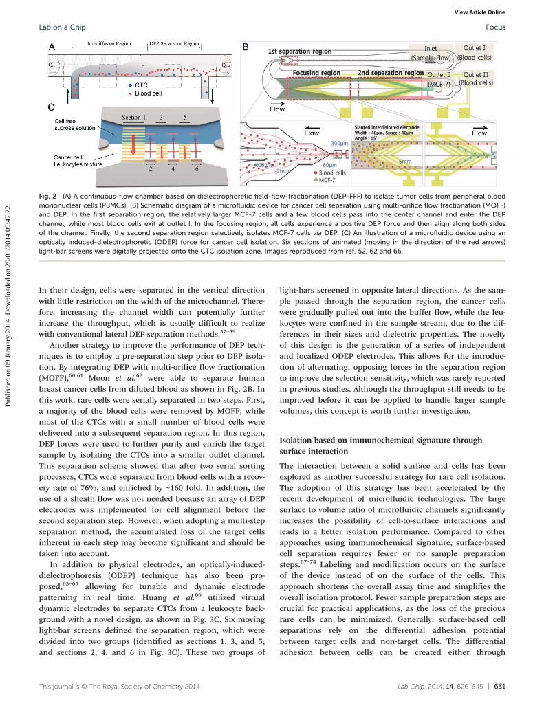
Fig. 2 (A) A continuous-flow chamber based on dielectrophoretic field-flow-fractionation (DEP-FFF) to isolate tumor cells from peripheral bloodmononuclear cells (PBMCs). (B) Schematic diagram of a microfluidic device for cancer cell separation using multi-orifice flow fractionation (MOFF)and DEP. In the first separation region, the relatively larger MCF-7 cells and a few blood cells pass into the center channel and enter the DEPchannel, while most blood cells exit at outlet I. In the focusing region, all cells experience a positive DEP force and then align along both sidesof the channel. Finally, the second separation region selectively isolates MCF-7 cells via DEP. (C) An illustration of a microfluidic device using anoptically induced-dielectrophoretic (ODEP) force for cancer cell isolation. Six sections of animated (moving in the direction of the red arrows)light-bar screens were digitally projected onto the CTC isolation zone. Images reproduced from ref. 52, 62 and 66.
Lab on a Chip Focus
Publ
ishe
d on
09
Janu
ary
2014
. Dow
nloa
ded
on 2
9/01
/201
4 09
:47:
22.
View Article Online
In their design, cells were separated in the vertical directionwith little restriction on the width of the microchannel. There-fore, increasing the channel width can potentially furtherincrease the throughput, which is usually difficult to realizewith conventional lateral DEP separation methods.57–59
Another strategy to improve the performance of DEP tech-niques is to employ a pre-separation step prior to DEP isola-tion. By integrating DEP with multi-orifice flow fractionation(MOFF),60,61 Moon et al.62 were able to separate humanbreast cancer cells from diluted blood as shown in Fig. 2B. Inthis work, rare cells were serially separated in two steps. First,a majority of the blood cells were removed by MOFF, whilemost of the CTCs with a small number of blood cells weredelivered into a subsequent separation region. In this region,DEP forces were used to further purify and enrich the targetsample by isolating the CTCs into a smaller outlet channel.This separation scheme showed that after two serial sortingprocesses, CTCs were separated from blood cells with a recov-ery rate of 76%, and enriched by ~160 fold. In addition, theuse of a sheath flow was not needed because an array of DEPelectrodes was implemented for cell alignment before thesecond separation step. However, when adopting a multi-stepseparation method, the accumulated loss of the target cellsinherent in each step may become significant and should betaken into account.
In addition to physical electrodes, an optically-induced-dielectrophoresis (ODEP) technique has also been pro-posed,63–65 allowing for tunable and dynamic electrodepatterning in real time. Huang et al.66 utilized virtualdynamic electrodes to separate CTCs from a leukocyte back-ground with a novel design, as shown in Fig. 3C. Six movinglight-bar screens defined the separation region, which weredivided into two groups (identified as sections 1, 3, and 5;and sections 2, 4, and 6 in Fig. 3C). These two groups of
This journal is © The Royal Society of Chemistry 2014
light-bars screened in opposite lateral directions. As the sam-ple passed through the separation region, the cancer cellswere gradually pulled out into the buffer flow, while the leu-kocytes were confined in the sample stream, due to the dif-ferences in their sizes and dielectric properties. The noveltyof this design is the generation of a series of independentand localized ODEP electrodes. This allows for the introduc-tion of alternating, opposing forces in the separation regionto improve the selection sensitivity, which was rarely reportedin previous studies. Although the throughput still needs to beimproved before it can be applied to handle larger samplevolumes, this concept is worth further investigation.
Isolation based on immunochemical signature throughsurface interaction
The interaction between a solid surface and cells has beenexplored as another successful strategy for rare cell isolation.The adoption of this strategy has been accelerated by therecent development of microfluidic technologies. The largesurface to volume ratio of microfluidic channels significantlyincreases the possibility of cell-to-surface interactions andleads to a better isolation performance. Compared to otherapproaches using immunochemical signature, surface-basedcell separation requires fewer or no sample preparationsteps.67–74 Labeling and modification occurs on the surfaceof the device instead of on the surface of the cells. Thisapproach shortens the overall assay time and simplifies theoverall isolation protocol. Fewer sample preparation steps arecrucial for practical applications, as the loss of the preciousrare cells can be minimized. Generally, surface-based cellseparations rely on the differential adhesion potentialbetween target cells and non-target cells. The differentialadhesion between cells can be created either through
Lab Chip, 2014, 14, 626–645 | 631

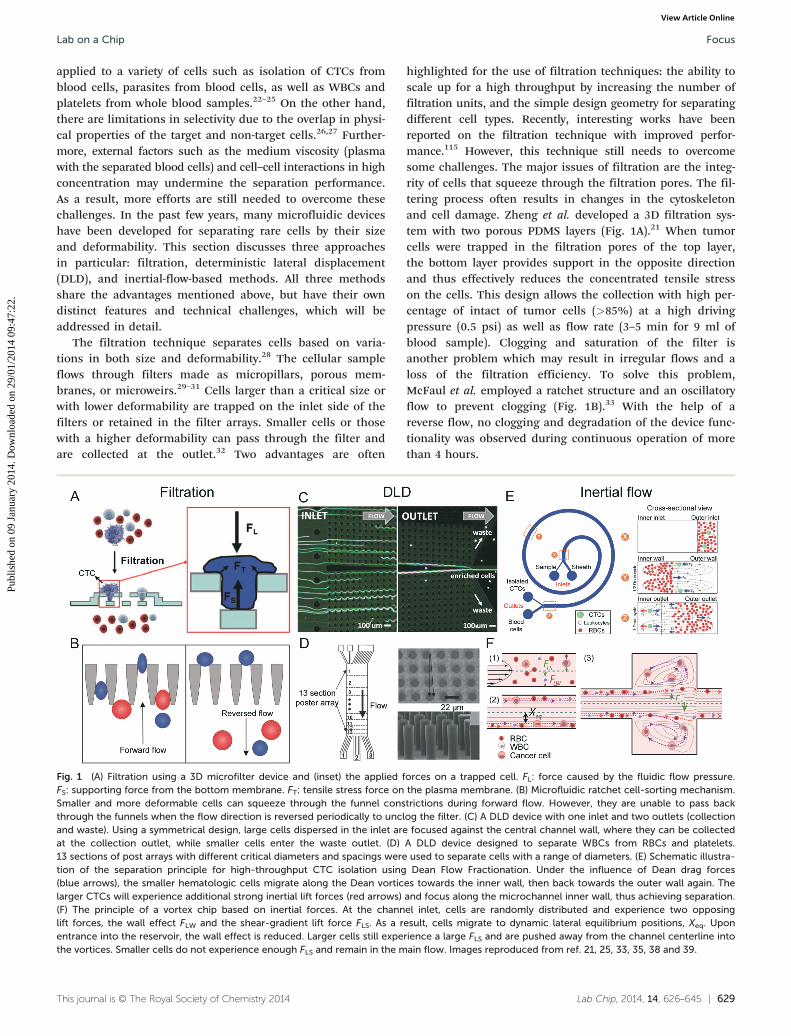
Fig. 3 (A) Schematic showing the chemical conjugation between the functionalized graphene oxide nanosheets and the EpCAM antibodies.Graphene oxide nanosheets are adsorbed onto the gold pattern. The N-γ-maleimidobutyryloxy succinimide ester (GMBS) crosslinker binds toPL–PEG–NH2 on the graphene oxide nanosheets. The NeutrAvidin is connected to the GMBS and biotinylated EpCAM. (B) Enhanced cell transportto a fluid-permeable capture surface is achieved by diverging streamlines. Gentle cell rolling and arrest on the capture surface occurs due toreduced shear and increased cell–surface interactions. (C) Isolation and detection of cancer cells in whole blood using a long, multivalent DNAaptamer-based microfluidic device. The magnified box illustrates a captured cell bound by several long DNA molecules via multiple aptamerdomains (red colored sections). (D) Schematic of a nanotopography generated by RIE on a glass surface. The inserts show a magnified illustration(right) and SEM (left) images of cancer cells captured on the nanoroughened glass surfaces. Images reproduced from ref. 90–92 and 99.
Lab on a ChipFocus
Publ
ishe
d on
09
Janu
ary
2014
. Dow
nloa
ded
on 2
9/01
/201
4 09
:47:
22.
View Article Online
immobilizing immunoaffinity-binding molecules or imple-menting specific surface patterns. In positive selection mode,target cells should preferably bind to the surface, whereasnon-target cells have minimum specific interactions with thesurface. After applying an optimum shear stress (typically byadjusting the flow rate), the separation of target cells fromnon-target cells can be achieved. The “optimum shear stress”is the balance between the separation efficiency and thepurity. In practice, it is almost impossible to find a shearstress level for both best separation efficiency and highestpurity. Thus, it is always important to understand whichparameter is the more critical for the specific cell separationapplication. A higher shear stress tends to give a betterpurity, as it is able to remove non-specifically bound cellsmore efficiently. Lower shear stress allows for better interac-tion between cells and the surface and favors higher separa-tion efficiency. For rare cell isolation, finding all the rarecells is always the highest priority, so separation efficiency ismore important than purity. However, in practice, theshear stress or flow rate cannot be too low and takes too
632 | Lab Chip, 2014, 14, 626–645
much time, especially for isolation of rare cells that requiresscreening a large sample volume. Therefore, the key for usingsurface-based separation in rare cell applications is to increasethe throughput as much as possible while maintaining ahigh efficiency.
Due to the dominant laminar flow regime, cells tend tofollow the streamline in microchannels. However, laminarflow also prevents effective interaction between cells and thesurface. Thus, many previous studies focused on modifyingthe surface of microchannels to enhance cell–surface interac-tions. Nagrath et al. fabricated 78 000 silicon microposts in amicrochannel and reported the successful capture of CTCsusing the anti-EpCAM antibody from clinical samples.75 Thelarge amount of microposts significantly increases the sur-face area for cell capture compared to flat straight channels.Moreover, the possibility of cell–surface interaction is furtherenhanced if laminar flow streams are disrupted by the stag-gered array of microposts. Gleghorn et al. used a micropostarray to create size dependent enhancement of cell–surfaceinteractions.76 The array of microposts favored the capture of
This journal is © The Royal Society of Chemistry 2014

Lab on a Chip Focus
Publ
ishe
d on
09
Janu
ary
2014
. Dow
nloa
ded
on 2
9/01
/201
4 09
:47:
22.
View Article Online
larger cancer cells over the smaller blood cells, resulting inbetter capture purity. Sheng et al. also reported the use ofmicropost structures for capturing CTCs using an aptamercoated surface.77 In addition to the micropost strategy, Soperand coworkers reported a CTC capture device with highaspect ratio (35 μm width and 150 μm height) andsinusoidal-shaped channels.78–81 These optimized micro-channels lead to the successful capture of CTCs from a 1 mLblood sample in 37 min. Stott et al. implemented herring-bone structures in a microfluidic channel to enhance cell–surface interaction.82 The herringbone structures generatechaotic advection enabling rapid fluid mixing. The resultingchaotic flow also helps to increase the chance of cell–surfaceinteraction. Stott et al. showed that a capture efficiency of92% was achieved with a similar flow rate to the micropost-based CTC-chip. The herringbone chip not only improves theperformance of the previous device but also simplifiesthe fabrication process. This design has been adopted byother surface-based rare cell capture devices.83,84 Recently,Sheng et al. further enhanced the capture efficiency andpurity of the herringbone chip by increasing the groovewidths, and applying the optimized device to monitorpatients' response to therapy.85
Since specific binding only occurs on the surface, modify-ing the surface is another important direction to improve theperformance of isolation devices based on surface interac-tions. Improved efficiency has been reported from usingsurfaces patterned with nanostructures. Nanostructures onthe surface facilitate cell binding by increasing the surfacearea and disturbing the flow. Wang et al. patterned the sur-face with silicon nanopillars and showed improved cell cap-ture as compared to a flat surface.86 Combining herringbonestructures in a microfluidic channel, a capture efficiency of 95%for MCF-7 cells was achieved with a flow rate of 1 mL h−1.84
Halloysite nanotubes, multivalent DNA nanospheres, and TiO2
nanoparticles have been studied and demonstrated theirabilities to enhance cell capture on the surface.83,87–89 Recently,Yoon et al. reported the isolation of CTCs on functionalizedgraphene oxide nanosheets.90 Flower-shaped gold patterns(58 957 flowers over 100 × 100 μm) were first deposited on aflat silicon substrate (Fig. 3A). Graphene oxide was thenadsorbed onto the gold surface. After coated with anti-EpCAM,the device isolated MCF-7 cells with a capture efficiency of82% and a throughput of 3 mL h−1. Mittal et al. fabricated aporous membrane for cell capture in a sandwiched micro-fluidic flow channel (Fig. 3B).91 The pore size of the mem-brane is 200 nm, allowing the fluid to pass while retainingcells on the surface. Since the fluid is able to pass along thebottom surface, an additional flow towards the surface existsand forces cells to interact with it. As a result, this deviceallows for a much higher flow rate while maintaining thesame level of capture efficiency. The authors reported a 20-foldincrease in flow rate as compared to a solid surface device.Inspired by creatures of nature such as jelly fish, whichuse long tentacles to capture flowing particles, Zhao et al.immobilized long chain DNA molecules (10–100 micrometers)
This journal is © The Royal Society of Chemistry 2014
on the channel surface (Fig. 3C).92 The DNA molecules containrepeated specific aptamer sequences to recognize target cells.The long-chain DNA molecules extend into the flow and increasethe accessibility of aptamer to cells, avoiding the detrimentalboundary effects at the surface. The authors compared theaptamer-coated device with a CTC-chip and a silicon nano-pillar chip, and demonstrated a higher capture efficiency at aflow rate of 2 mL h−1.
One major limitation for surface-based isolation of rarecells is the difficulty in releasing viable cells after capture.Releasing with elevated shear stress has a low efficiency andcauses excessive dilution of the sample. More importantly, ahigh shear stress very likely damages the cells. Another com-mon option for releasing isolated cells is enzyme digestion.However, enzyme digestion may require a prolonged diges-tion time and damages cells during the digestion process.Shen et al. replaced the capture antibody with an aptamer forcapturing lung cancer CTCs.93 Because an aptamer is an oli-gonucleotide, it can be cleaved using a nuclease solutionwithout disturbing the cells. Several groups employed ther-mal responsive materials to achieve the highly efficient andviable release of cells.94–97 Poly(Nisopropyacrylamide)(PNIPAAm) is a widely used thermally responsive materialfor releasing captured cells. PNIPAAm is hydrophobic at atemperature above its lower critical solution temperature(LCST) of 32 °C. When the temperature is below 32 °C, thematerial becomes hydrophilic due to the hydration of itsmolecules. A hydrophilic surface is not preferable for proteinadsorption, so cells can be removed with a mildly elevatedshear stress. After release, a viability of 94% has beenreported. Plouffe et al. utilized an aqueous alginate solutionand achieved the release of viable cells.98 At room temperature,aqueous alginate can form a hydrogel after adding calciumions. This process is reversible. A calcium ion chelator,such as EDTA, can transform the hydrogel back to itsliquid state and allow for the release of the cells. No signifi-cant change in cell viability was reported from using thisprocess.
Fu et al. reported the successful specific capture ofcancer cells on glass surfaces with a random nano-roughness(Fig. 3D).99 The separation of cancer cells from blood cellswas achieved through their differential adhesion preference.Cancer cells are more likely to attach on the rough glasssurface generated by reactive ion etching (RIE). Compared toother surface-based cell capture methods, this method isunique because it does not require specific recognitionmolecules. The method has the potential to become animportant complementary approach to the existing antibody-based surface capture methods. However, this strategy stillneeds more validation using clinical samples before it can beadopted widely.
Isolation based on magnetophoretic signature
An isolation method based on magnetophoresis has beendeveloped for years as a relatively mature and reliable
Lab Chip, 2014, 14, 626–645 | 633

Lab on a ChipFocus
Publ
ishe
d on
09
Janu
ary
2014
. Dow
nloa
ded
on 2
9/01
/201
4 09
:47:
22.
View Article Online
technique for microfluidic-based rare cell isolation.100–104
This concept uses a magnetic field gradient to selectivelyisolate magnetic-particle-labeled cells from the sample flow,and thus is also called an immunomagnetic technique.Compared to the passive hydrodynamic approaches, such asinertial microfluidics and DLD, immunomagnetic-based sep-aration actively applies a strong magnetic force to extractthe magnetic-particle-labeled cells, which is less dependenton the flow conditions and particle–particle interactions.Therefore, this technique is able to achieve a higherspecificity, and is possible to process whole blood in ahigh-throughput manner.105–107 Furthermore, the immuno-magnetic technique is a biocompatible approach with lowdamage to the cells. Although a high-gradient magnetic fieldis used, the forces are not directly applied on cells. Ithas been reported that almost 100% viability can be achievedwith this method.108 The most obvious limitation of thistechnique is the requirement for a label, and henceadditional sample preparation steps are required.
Among the immunomagnetic approaches, lateral magneto-phoresis is a common method for cell separation. Thismethod utilizes a horizontal magnetic field to drag labeledtarget cells from the sample flow into the buffer flow(Fig. 4A).109 Lateral magnetophoresis has been demonstratedas a robust technique for rare cell separation with a high
634 | Lab Chip, 2014, 14, 626–645
Fig. 4 (A) Schematic of a magnetophoretic microdevice with two inlets ansource path are pulled across the laminar streamline boundary into the(B) Capture principle of a magnetic sifter. A whole blood sample is labelexternal magnetic field. Magnetically labeled target cells are captured at thpass through the pores. (C) Operating principle and practical implemenpatterned on the bottom of a microfluidic channel. The application of anregular array of magnetic bead columns localized on top of the ink dots. Acolumns. Images reproduced from ref. 107, 109 and 111.
throughput and a high recovery rate. A typical example isthe magnetophoretic microseparator reported recently byKim et al. to isolate CTCs from human peripheral blood.108
After specifically binding to immunomagnetic beads, CTCisolation was performed via lateral magnetophoresis. Dilutedblood samples spiked with CTCs were tested with this device,achieving a high recovery rate of ~90% and a purity of 97%at a flow rate up to 5 mL h−1. However, this design requiresa buffer flow and may dilute the collected target sample.Zhang et al. replaced the lateral magnetic field gradient by avertical version, and isolated rare cells from a continuousblood sample flow. This method does not require any bufferflow and allows for simultaneous sample concentration witha high capture efficiency.106,110
Unlike conventional magnetophoresis,108 which imagesand analyzes the isolated rare cells on a separate cover slip,Earhart et al. recently developed a magnetic sifter for inte-grated on-chip separation, imaging, and analysis of rare cellsas shown in Fig. 4B.107 A magnetic porous structure enabledthe passage of cellular samples and generated sufficient mag-netic forces to capture the labeled cells. The isolation of rarecells was simply performed by passing the sample throughthe magnetic sifter. Upon the application of an externalmagnetic field, CTCs labeled with magnetic beads weretrapped at the pore edges, while non-labeled blood cells were
This journal is © The Royal Society of Chemistry 2014
d two outlets. Inset shows how magnetic beads flowing from the upperlower collection path when subjected to a magnetic field gradient.
ed with magnetic tags and pumped through the pores by an appliede pore edges where high magnetic field gradients exist. Unlabeled cellstation of the Ephesia system. A hexagonal array of magnetic ink isexternal vertically-aligned magnetic field induces the formation of after the passage of 400 Raji cells, numerous cells are captured on the

Lab on a Chip Focus
Publ
ishe
d on
09
Janu
ary
2014
. Dow
nloa
ded
on 2
9/01
/201
4 09
:47:
22.
View Article Online
removed by the flow. CTC isolation from human wholeblood was realized with this magnetic sifter at a flow rate of10 mL h−1, achieving a high recovery rate of ~90%. The directcontact between the magnetic material and the sample flowis crucial for improving the isolation efficiency. Moreover, byremoving the external magnetic field, isolated rare cells werereleased and collected at the outlet after on-chip imagingand analysis.
As mentioned at the beginning of this section, the require-ment for a label in this technique requires an additionalsample pretreatment step. To address this issue, Viovy et al.invented an unconventional immunomagnetic separationmethod shown in Fig. 4C.111 Instead of labeling the targetcells, antibody-conjugated magnetic beads were dynamicallyassembled into an array of columns in the microfluidicchannel with the help of the pre-patterned magnetic traps onthe substrate. As a result, when the sample flows throughthe channel, cells with specific biomarkers are captured bythe assembled magnetic beads. Recently, this device hasbeen applied to CTC isolation by Svobodova et al.112,113
Though the sample preparation step was avoided by thismethod, labeled magnetic beads are still needed. The mecha-nism of this method is similar to the immunocapture-based cell isolation. However, the superiority of this methodlies in the dynamically assembled microstructures (magneticmicrobeads), allowing for controllable release and recon-struction using an external magnetic field. To achieve high-throughput rare cell isolation, the magnetic forces forassembly need to be strong enough to overcome the highflow velocity.
This journal is © The Royal Society of Chemistry 2014
Table 1 Summary of various rare cell isolation techniques
Techniques Sample type Flo
Filtration MCF-7 breast cancer cells 3 mBreast, gastric, and colon tumor cells 1 mBreast and colon cancer cells 12Hematopoietic stem cells 17MCF-7 breast cancer cells 25
DLD MDAMB231, PC3, MCF10A cancer cells 10T. brucei parasites in blood 60
Inertial fluidics HeLa and MCF7 cancer cellsMCF-7, MDA-MB-231, HeLa cells 50MCF-7, T24 and MDA-MB-231 cells ~1Nucleated cells in blood >3MDA-MB-231 breast cancer cells 56
DEP SKOV3 and MDA-MB-231 cancer cells 18Rare bacteria in blood 5 μMDA-MB cancer cells 20MDA-MB cancer cellsProstate tumor initiating cells 4 μ
Immunocapture Leukemia cells 36Circulating tumor cells 20Lymphoblast CCRF-CEM cells 1μCirculating tumor cells 34Prostate cancer circulating tumor cells 17
Immunomagnetic M6C breast cancer cells 20MCF7 breast cancer cellsC. albicans fungi in blood 33H1650 cancer cells 17COLO205 and SKBR3 cancer cells 17
Summary of rare cell isolationmethods and devicesTable 1 summarizes the performance of each rare cell isola-tion technique previously introduced in terms of volu-metric flow rate, efficiency, purity, and cell viability. Due tothe differences in cell types and sample concentrations ineach study, we are unable to draw a definitive conclusionabout which technique is superior based on the datareported. Even using the same mechanism, devices with dif-ferent designs varied in their results. However, some generalpatterns are observed and can be summarized into designrules. The cell samples used in these studies reveals thatmany research works have focused on CTC isolation fromwhole human blood, because of their great clinical signifi-cance in cancer diagnostics and therapy. Nevertheless,these techniques have also been applied to isolate stemcells, parasites, and bacteria, demonstrating their generalapplicability. From an engineering point of view, cell isola-tion based on physical properties can obtain a higher volu-metric flow rate than other isolation techniques. Filtration,DLD, and inertial fluidic techniques have been reported withan operating flow rate of more than 1 mL min−1. This highflow rate is rarely found in other techniques. However, theflow rate does not reflect an actual throughput, which isdefined as the total amount of cells processed per unit time.As a result, the sample concentration should also be considered.In this respect, the immunomagnetic and immunoaffinity-based methods show a higher ability to process human wholeblood without any dilution. Other techniques including
Lab Chip, 2014, 14, 626–645 | 635
w rate Efficiency Purity Viability Ref.
L min−1 87% 85% 21L min−1 >80% 98% 22μl min−1 >80% >80% 32.2 μL min−1 >98% >90% 114–100 μl min−1 90%–50% 115mL min−1 >85% >95% 35nL min−1 99% 23
23% 85% 116μL min−1 >85% ~10% 98% 38mL min−1 >80% >90% 1170 μL min−1 >90% 1185 μL min−1 85% 119–25 μL min−1 68.3% 97.1% 54L min−1 95% 42μL min−1 70%–80% 52
>90% 10% ~90% 56L min−1 61%–70% 50μL min−1 ∼95% ∼81% ∼93% 770 μL min−1 92% 14% 95% 82L min−1 ∼80% ~38% 66% 92μL min−1 65% 50% 98% 75μL min−1 >80% 62% 760 μL min−1 90% >90% 103
60% 50% 1000 μL min−1 80% 1050 μL min−1 96% 1070 μL min−1 86%–90% 106

Lab on a ChipFocus
Publ
ishe
d on
09
Janu
ary
2014
. Dow
nloa
ded
on 2
9/01
/201
4 09
:47:
22.
View Article Online
physical-property-based isolation, as well as DEP approaches,usually require sample dilution, and some of them need sheathflows or buffer flows as well. Most of the studies have charac-terized the efficiency but only some of them reported thepurity, because the capture efficiency is more important forrare cell isolation. Generally, a higher efficiency can beachieved by decreasing the flow rate. Therefore, a compromiseshould be found between the isolation efficiency and through-put. The purities in different studies were varied from 10% to90%, while an efficiency higher than 80% is usually preferred.The average efficiency of all the studies listed in Table 1 iscalculated to be ~82%. Moreover, most of the reported cellviabilities are higher than 90%.
Obviously, every technique has its own limitations. Forexample, filtration for cell separation is a label-free, high-throughput approach, but its specificity is relatively low dueto the possible overlap in cell sizes, making it not applicableto all sample types. On the other hand, cell isolation basedon immunocapture has a high specificity, but the throughputis limited by effective cell–surface interactions. One strategyto improve the performance of rare cell separation is thecombination of two or more separation mechanisms. Severalworks have explored this direction, including the use ofDEP with immunocapture,120,121 DEP with DLD,122 DLD withimmunocapture,123 as well as immunoaffinity with hydro-dynamic force.124 Another strategy is to explore novel separa-tion techniques and physical phenomena to overcome theexisting challenges in rare cell isolation. For example, in the pastfew years, acoustofluidics has paved a new way for particle–cellseparation.125–127 Recently, Adams et al. demonstrated an ultrahigh-throughput (1 L h−1) acoustophorestic microdevice, whichwas able to remove RBCs from human whole blood with anefficiency up to 95%.128 Acoustic waves have also been utilizedto separate prostate cancer cells from white blood cells(WBCs),129 and sorting of viable MCF-7 breast tumor cells fromnonviable cells.130 Although acoustic-wave-based rare cell sepa-ration is still at an early research stage, further developmentand optimization may lead to a useful technique for rarecell separation because of its advantages of high throughput,label-free nature, and noninvasiveness.131–135
Rare cell analysis methods anddevices
The subsequent step after isolation of rare cells is theiranalysis. Cell analysis is important for fundamental cellularstudies, drug discovery, diagnostics, and prognostics. Theanalysis is usually conducted at the molecular level (DNA,RNA, protein, secreted molecules, etc.) or at the cellular level(cell metabolism, cell morphology, cell–cell interactions, etc.).For the analysis of rare cells, a high throughput and a highsensitivity are often required for the chosen analyticalmethods and devices, because of their extremely low abun-dance and the associated high level of noise. In this respect,microfluidics provides an ideal platform for rare cell studies,due to the simplified handling of small sample volumes,
636 | Lab Chip, 2014, 14, 626–645
multiplexing capabilities, and large surface-to-volumeratios.136,137 Rare cell studies using microfluidics are carriedout either in stationary fluids or in continuous flows. Bothmethods have their own scope of corresponding applications.Stationary fluids are usually preferred for cell studies at themolecular level, while both methods have been adoptedin the studies at the cellular level. Over the past decade,a variety of microfluidic techniques have been developedbased on these two modes, which will be introduced andillustrated below by representative examples. A small numberof these techniques have been applied to study specificbiological questions, while most of them still remain at theproof-of-concept stage.
Rare cell analysis in stationary microfluidics
In stationary microfluidics, the cell sample is fixed in themicrofluidic device for long-term cell culture, biochemicalreactions, and signal detection.138 This analysis approachallows for the detection of low-intensity signals by enhancingthe exposure time, and also allows for monitoring thedynamic cellular responses with time-lapsed imaging. Here,the advantages of miniaturization techniques over conven-tional approaches (e.g., cells in a Petri dish culture) manifestin terms of a high-throughput capability, usually by isolatingcells in a large multiplex microarray for parallel processing,even at single-cell resolution.139,140 These high-density arraysare often microstructures (microwells, microchamber, etc.)fabricated by photolithography, or microdroplets generatedin situ to encapsulate multiple cells or single cells.136 Oneexample developed by the Quake group using themicrostructure-based approach is the fabrication of dynamicarrays on a chip for genetic analysis.141 In their design, thou-sands of PDMS-based microchambers were created with con-trollable microvalves for performing single-cell real-timePCR.142–144 This technique has recently been applied tosingle-cell profiling of CTCs, and provided an early insightinto CTC heterogeneity.145
One of the challenges for rare cell analysis at the molecularlevel is the ability to detect low-intensity signals. The smallvolumes (from pL to nL) in microdevices restricts signaldilution in the fluidic environment. Some new microfluidic-based bioengineered approaches for the enhancement ofdetection sensitivities have also been reported in the pastfew years.146–148 The on-chip rolling-circle-enhanced enzymeactivity detection (REEAD) technique presented by Juul et al.is a typical example (Fig. 5A).149 In their studies, the REEADtechnique was used to quantify single enzymatic events(hTopl or Flp recombinase activities) in rare cells with a back-ground of wild-type cells. The single cells were encapsulatedinto an array of picoliter droplets for lysis and enzymatic reac-tions (top image in Fig. 5A). Since the recombinase reactionproducts (circular DNA) were too small to be detected usingmicroscopes, an isothermal rolling circle amplification (RCA)was then carried out to convert the circular DNA into afluorescently-labeled, long-chain tandem repeat products
This journal is © The Royal Society of Chemistry 2014

Fig. 5 (A) A microdevice for rolling-circle-enhanced enzyme activity detection (REEAD) assay for the specific detection of single enzymatic events.The droplets are confined in a drop-trap on a primer-coated glass slide on which isothermal rolling circle amplification (RCA) takes place.(B) Schematic of the microarray layout with 96 wells with the 6 × 5 mm2 scanning area shaded. Inset shows a finite element model of fluid flowthrough a microwell. The fluorescence images show the H2B-EYFP-labeled PtK2 cells in a single microwell after seeding (left); 12 h later (right),they attached, spread, and divided (*). Scale bar: 100 μm. (C) Schematic of optical trapping of a single cell for Raman spectroscopy. (D) (Left) Amicrodevice for graphene-based detection of single Plasmodium falciparum-infected erythrocyte. (Right) Specific binding between ligands locatedon positively charged membrane knobs of infected erythrocyte and CD36 receptors on the graphene channel produces a distinct conductancechange. The conductance returns to a baseline value when the parasite-infected erythrocyte exits the graphene channel. (E) A microdevicefor hydrodynamic deformability cytometry. The first opposing pair of microchannel branched flows impact the cell suspension perpendicularly toperform hydropipetting. The second pair of channels flows towards the cell suspension, forming an extensional flow to perform deformabilitycytometry. (F) (Left) Schematic of the microfluidic cell rolling cytometer, in which cells are forced into contact with adhesion molecule-coatedridges. (Right) Cross-section views of the cell rolling cytometer. Specific adhesion interactions retard the cell and change its trajectory. Withoutspecific interactions, a cell quickly travels through the channel, following the focusing trajectory. Images reproduced from ref. 149, 152, 154, 165,168 and 170.
Lab on a Chip Focus
Publ
ishe
d on
09
Janu
ary
2014
. Dow
nloa
ded
on 2
9/01
/201
4 09
:47:
22.
View Article Online
(left bottom image in Fig. 5A). This critical signal-amplification step enabled the visualization of fluorescencesignals from the tandem repeat products, and hence thedirect quantification of single enzyme activities (right bottomimage in Fig. 5A). Although the REEAD assay has beendemonstrated in an off-chip manner before, the spreading ofsignals in a large reaction volume (~9 mm2) makes it lesssensitive.150 The on-chip REEAD assay in this work was able toachieve single-cell resolution and the limit of detection (LOD)was increased by >100 fold compared with the traditional“large-volume” assay.
Rare cell studies at the cellular level are usually appliedfor cell identification, monitoring of cellular kinetics, as wellas the measurement of cell properties, such as mechanical,optical, and immunochemical properties.137,151 In stationarymicrofluidics, the microenvironment can better mimicin vivo conditions. Moreover, the miniaturized microdevices
This journal is © The Royal Society of Chemistry 2014
allow for fully-integrated parallel processing with improvedefficiency and throughput, which are especially importantfor rare cell events. In a traditional macro-scale setup, cellu-lar kinetic studies are only optimized for either high spatio-temporal resolution or high experimental throughput. Tofind a balance between imaging resolution and experimentalthroughput, Albrecht et al. developed a microfluidic-basedtime-lapsed imaging platform for rare cell event detection, asillustrated in Fig. 5B.152 This microdevice contains a 96microwell array (6 × 5 mm2 scanning area), divided into fourseparate fluidic circuits. Each circuit had a common inletand outlet for sample loading and medium exchange usinga pipette. The platform can be used to study the dynamicresponses of cells, such as mitotic kinetics and spindleorientation dynamics. At a high imaging resolution, thismicrodevice was able to achieve a much higher throughputas compared to other traditional approaches. For example, a
Lab Chip, 2014, 14, 626–645 | 637

Lab on a ChipFocus
Publ
ishe
d on
09
Janu
ary
2014
. Dow
nloa
ded
on 2
9/01
/201
4 09
:47:
22.
View Article Online
5 day experiment conducted on this microfluidic platformachieved comparable results that would have taken morethan a month to finish processing using the single-wellmicroscopy. In addition, the day-to-day variability was alsosuppressed with this platform owing to the high-resolutionparallel analysis.
In order to measure the optical properties of cells, it issometimes necessary to immobilize cells using microfluidics.Raman scattering is a label-free method for cell identificationand characterization.153 However, this method requires alonger time to measure the signal compared with fluores-cence detection. Recently, Liberale et al. demonstrated anintegrated optical tweezers for three-dimensional (3D) immo-bilization of single cells as shown in Fig. 5C.154 In this setup,a four optical fiber bundle was incorporated into the sub-strate of the microdevice to generate four independentlaser beams. Four micro prisms located at the top of thefibers then refracted the laser lines towards a focal point for3D trapping of the cells (top image of Fig. 5C). These minia-turized optical tweezers allowed for the long-term interroga-tion of single cells by immobilizing them at a stable positionin a non-contact manner, with more control in the verticaldirection compared with conventional 2D optical tweezers.Using this tool, the distinct Raman signature of a coloncancer cell was successfully measured (bottom image ofFig. 5C). However, the throughput was relatively low. Toimprove the throughput for rare cell scanning, a large arrayof micro-optical tweezers for simultaneous trapping andmeasurement is preferred.
Rare cell analysis in continuous-flow microfluidics
Microfluidic platforms have become a powerful tool to inves-tigate rare cells in continuous flow or microfluidic cytometry.Because of its single-cell resolution, the rare cell sample candirectly go through the system without prior separation orpurification. Fluorescence intensity, wavelength, and lightscatter are the most commonly used parameters in conven-tional flow cytometry.155 Microfluidic cytometry shows agreater diversity in the biomarkers, which enables theanalysis of cells from different perspectives. In addition to theconventional optical parameters,156 microfluidic cytometryis also capable of measuring other parameters, such as electri-cal properties (conductance, impedance),157–159 mechanicalproperties (deformability, stiffness),155,156 magnetic properties(magnetic resistance, Hall effect),162,163 adhesion behaviors,164
and other optical properties (brightness with two-photonexcitation, fluorescence lifetime).155
Electrical signals have been widely used as a characteristicsignature in microfluidic cytometry for cell identification,cell counting, and differentiation of cell states, due to itshigh sensitivity and compatibility to be integrated withmicrofluidic systems.157–159 Ang et al. developed a graphene-based flow sensor to detect malaria-infected red blood cellsin a “flow-catch-release” method as shown in Fig. 5D.165
As the blood sample flows through the microchannel which
638 | Lab Chip, 2014, 14, 626–645
was integrated with a graphene-transistor array, malaria-infected red blood cells were temporarily captured by thesurface-functionalized graphene, resulting in changes in theelectrical conductance. By characterizing the conductancedwell times, cells at different stages of infection could beidentified. The electrical signal-based flow cytometers canlead to a highly compact and cost-effective system for label-free rare cell sensing by eliminating the need of a high-powerlaser and an expensive optics system. Moreover, an optics-free approach is much easier to develop a parallel processingmodel by implementing large-scale integrated electroniccircuits.
In the past few years, the mechanical properties of cellshas drawn more attention as a biomarker arising from itshigh correlation to certain diseases.166 A variety of workshave been reported to explore the mechanical properties oftumor cells, parasite-infected red blood cells, and stemcells.160,161,167 Recently, Dudani et al. developed a high-throughput (65 000 cells s−1) microfluidic cytometer for label-free, cellular-mechanical phenotyping based on pinched-flowhydrodynamic stretching as shown in Fig. 5E.168 Theinertially-focused cells were deformed by hydrodynamicforces when they were delivered to the center of an exten-sional flow. The cell deformability was then characterizedwith the assistance of high-speed microscopic imaging andan automated image analysis program. The throughput ofthis work was higher by over an order of magnitude than thatreported previously by the same group. This improvementwas achieved by the integration of a “hydropipetting” unit,which squeezed cells with perpendicular high-speed pinchflows and thus reducing their residence time at the stagna-tion point of the extensional flow.
The dynamic adhesion behavior of cells has also beenapplied as a specific biomarker for phenotyping of rare cells.However, the conventional parallel-plate chambers have poortethering or contact efficiency, which might reduce their sen-sitivities and performance.169 To overcome this limitation,Choi et al. recently reported a novel microfluidic cell-rollingcytometer to quantify surface adhesion dynamics of mesen-chymal stem cells (MSC) as shown in Fig. 5F.170 Thiscytometer was constructed by creating an array of 3D ridges,coated with adhesion molecules (receptors) in a micro-channel. The cells first flowed into a narrow focusing chan-nel, in which the high shear stress limited cell rolling on thesurface. As cells went into the wider adhesion channel, thedecreased sheer stress resulted in the interaction betweencells and the adhesion ridges. The cells with specific ligandswere able to roll on the channel surface due to the combinedaction of the ligand–receptor interaction and the fluidic dragforce. These cells thereby followed the orientation of theridges into the gutter side. Conversely, the non-interactingcells just followed the flow direction and stayed in the focus-ing side. Using microscope observations, the transit timesand lateral positions of the rolling cells were characterizedwith single-cell resolution. This rolling cell cytometer wassensitive enough to quantify different levels of cellular
This journal is © The Royal Society of Chemistry 2014

Lab on a Chip Focus
Publ
ishe
d on
09
Janu
ary
2014
. Dow
nloa
ded
on 2
9/01
/201
4 09
:47:
22.
View Article Online
adhesion, revealing the differentiation states of MSCs, whichis beyond the ability of a conventional flow cytometer.
Applications of rare cell isolationand analysis
The previous sections discussed various microfluidic-basedmethods and devices for rare cell isolation and analysis.These techniques will need to be further optimized beforebeing applied to different cell types. Besides CTCs, othertypes of rare cells also have significant value in biomedicalresearch, diagnostics, and therapeutics. In this section, we willbriefly introduce the background and properties of severalcategories of rare cells in order to provide some direction forfuture applications and optimization of these techniques.
Circulating tumor cells (CTCs)
Carcinoma cells shed from primary tumor sites which circu-late in the blood stream are circulating tumor cells. They areconsidered to be closely related to cancer metastasis which isthe leading cause of cancer mortality. Preliminary studieshave indicated the role of CTCs in the prognosis and treat-ment of metastatic cancers.171–173 The first challenge in iso-lating CTCs is the low abundance of CTCs in a blood sample(normally 1–100 cells mL−1), which calls for methods withhigh throughput, recovery rate, and sensitivity. Second, isola-tion is more complicated due to the heterogeneity of CTCs.For example, many immunoaffnity methods rely on theexpression of epithelial markers (i.e., EpCAM) by CTCs. How-ever, tumor cells that are able to enter the blood stream mayundergo an epithelial–mesenchymal transition, resulting inthe down-regulation or negative expression of EpCAM.174
Even within the same patient sample, there may be differentsubpopulations of cancer cells, e.g., cancer stem cells(CSCs).18 To avoid the bias from biochemical detectionmethods, CTCs can also be isolated based on physical param-eters, such as size and deformability. The sizes of most CTCsare estimated in the range of 12–25 μm, which are largerthan most of the blood cells.30 But it should also be notedthat different types of cancers have different size distribu-tions for CTCs, some of which may overlap with bloodcells.175,176 The deformability is another possible parameterto differentiate CTCs and blood cells, but researchers shouldbe aware that the same population of CTCs may havedifferent deformabilities depending on the state of the cells.Zhang et al. reported that cancer cells with a higher meta-static potential showed a high deformability.160
Circulating endothelial cells (CECs) and circulatingendothelial progenitor cells (EPCs)
The disruption of endothelial function and integrity isclosely related with many pathological processes, includingthe presence of an infection, cancer, or cardiovascular dis-ease. One potential non-invasive approach to evaluate theintegrity of the endothelium is by detecting circulating
This journal is © The Royal Society of Chemistry 2014
endothelial cells in the blood. It has been reported thatthe number of circulating endothelial cells increases with thelevel of vascular damage due to a disease.177 Circulatingendothelial progenitor cells are considered to originate frombone marrow and play a role in the repair of damaged bloodvessels.178 Depending on the detection methods and thespecific disease, the concentration of CECs and EPCs in ahuman blood sample varies significantly with a typical rangebetween 1–10 000 cells mL−1.179 There is still no singlesurface biomarker to identify CECs and EPCs.180 Generally,CECs should have negative expression of a pan-leukocytemarker (CD45) and a primitive haemopoietic cell marker(CD133) and positive expression of endothelial markers(e.g., von Willebrand factor, VE-cadherin, CD105, andCD146).178,181 CD146 is the most widely used marker forimmunomagnetic isolation of CECs.182 For EPCs, theyshould also be positive for immaturity markers (CD34 andCD133) in addition to the expression of endothelialmarkers.180 The sizes of CECs range from 20 to 50 μm indiameter, whereas EPCs are normally less than 20 μm sincethey are immature cells.178
Fetal cells in maternal blood
Prenatal diagnosis of fetal cytogenetic characteristics is criti-cal to the identification of fetal autosomal abnormalities.Currently, this is achieved through amniocentesis or chori-onic villus sampling (CVS).183 However, these approaches areinvasive and thus increase the risk of fetal loss or maternalinjury. Therefore, developing non-invasive methods for pre-natal diagnosis is of great importance. Fetal cells circulatingin the maternal blood are the ideal candidates for non-invasive examination of the genetic information of a fetus.There are several types of fetal cells in maternal blood thatcan be used for diagnosis, including trophoblasts, leukocytes,and erythroblasts (nucleated red blood cells (NRBCs)).Among them, NRBCs are a more favored target as they arerelatively more abundant and have a shorter life-span, whichavoids contamination between pregnancies.184 These fetalcells are extremely rare. Current estimates range from 1–2cells per 1 mL to 1–3 cells per 30 mL.185 Furthermore, the iso-lation of fetal cells is complicated by the lack of surfacemakers. For NRBCs, immunomagnetic separation relies onthe depletion of CD45+ cells, or the positive enrichment ofCD71+ cells.186 NRBCs have diameters ranging from 9 to 12 μmand are reported to be more deformable than white bloodcells.29
Stem cells
Stem cells are undifferentiated cells with the potential todevelop into many different cell types. Stem cells can bebroadly classified into two types: embryonic stem cells andadult stem cells. Adult stem cells are mostly isolated frombone marrow, adipose tissue, and blood, from which thereare several different subpopulations. Among the differenttypes of stem cells, mesenchymal stem cells (MSCs) and
Lab Chip, 2014, 14, 626–645 | 639

Lab on a ChipFocus
Publ
ishe
d on
09
Janu
ary
2014
. Dow
nloa
ded
on 2
9/01
/201
4 09
:47:
22.
View Article Online
hemopoietic stem cells (HSCs) are highly attractive and havebeen intensively studied due to their promise in biomedicalapplications. Stem cells have a great value in medical thera-pies because they provide potential solutions for manyhuman diseases. For example, stem cells have been appliedto the treatment of leukemia via bone marrow transplanta-tion. High cell purity is often required in these clinicalapplications. However, high-purity isolation of stem cellsis challenging because of their rarity and various sub-populations. Since HSCs are larger than other cells in thebone marrow, size-based techniques are possible for HSCisolation.114 Besides, CD34 has been demonstrated as a usefulbiomarker for HSCs for immunoaffinity-based or immuno-magnetic isolation.187
Infected cells
Cells infected by viruses, bacteria, or parasites may causecell dysfunction and eventually cell death, resulting in seri-ous health complications. HIV-infected T cells (AIDS) andPlasmodium falciparum-infected RBCs (malaria) are examplesof infected blood cells. Early diagnosis of these infectionscan lead to effective treatment for the diseases. However, thelow number of infected cells at the early stage of infectionrequires techniques with a high sensitivity and throughput.These infections usually induce changes in cell properties,such as mechanical or biochemical properties, which mayprovide useful biomarkers to isolate infected cells from thehealthy ones. Malaria, with a relatively high mortality rateworldwide, has been widely studied using microfluidic tech-niques. The Plasmodium falciparum-infected RBCs have sig-nificant changes in cell deformability, as well as changes inmagnetic and electrical properties. As a result, differentmechanisms have been reported to isolate or analyze infectedRBCs.161,165,188,189 Notably, because malaria-infected RBCsbecome paramagnetic due to a malaria byproduct (hemozoin),a magnetic field gradient can be used to directly isolateinfected cells without the need for magnetic beads as labels.188
Bacteria
Bacteria are single-cell microorganisms. Most bacteria have adiameter between 0.5 and 5 μm, which is smaller than mosthuman cells (>5 μm). Their morphologies vary, includingspheres, rods, and spirals. Rapid detection of pathogenicbacteria, such as nontyphoidal Salmonella, E. coli, Vibriocholera, Shigella, and Campylobacter, is highly important infood safety. Moreover, bacteria circulating in the blood maycause bacteremia and blood poisoning, posing a threat tohuman health. The current standard method for diagnosis ofthese diseases is based on a blood culture, which is time-consuming and can easily be contaminated. Some studieshave also been reported to enrich and identify bacteria viamicrofluidic devices, which can be divided into two strate-gies. One is to enrich bacteria from blood cells based on theirdifferences, such as differences in physical or dielectricalproperties.59,190 Another method is conducted at the
640 | Lab Chip, 2014, 14, 626–645
molecular level by directly amplifying target nucleic acidswith microfluidic polymerase chain reaction (μPCR) tech-niques, followed by an identification process.191
Sperm cells
Sperm cells are produced in the male gonads by meioticdivision during the process of spermatogenesis. As malegametes, the morphology of sperm cells is quite differentfrom the somatic cells. Sperm cells have a tadpole-like shapewith a head (~5 μm in diameter), a connecting piece, and atail (~55 μm in length). They contain only one set of chromo-somes; therefore, they cannot divide and have a limited lifespan. As a rare cell, sperm cells are important in forensicinvestigations, especially in cases involving sexual assault.DNA extracted from sperm cells can be critical evidence usedto identify the perpetrator. However, the sperm cells collectedvia vaginal swabs are usually contaminated with a muchlarger background of the victims' epithelial cells. Before DNAprofiling, pretreatments of the sample, such as purificationand concentration of the sperm cells are necessary.192,193
Differential extraction is the conventional method for spermcell selection. Sperm cells can also be isolated from epithelialcells based on their significant difference in size.
Conclusions and perspectives
The present paper discusses the various techniques for isola-tion and analysis of rare cells as well as their applications.Table 1 indicates that it is difficult to compare the differentisolation methods quantitatively. A relatively high efficiencyabove 80% has been reported for most of the reviewed isola-tion methods. However, a benchmarking standard is lackingto effectively compare the different methods based onefficiency. With a standardized benchmarking method, theresults from different isolation methods could be collectedinto a design bank for effective comparisons of isolationdevices. Most of the reviewed works report only proof-of-concept devices. In order to be translated for use in a clinicalenvironment, these devices need to have a high efficiency, ahigh purity, and a high throughput. Improving cell integrityis another unmet need for future microfluidic devicesfocused on rare cell isolation. For extremely rare cells, thereis also a need to multiply the number of cells via an on-chipculture. Post-isolation cell cultures would increase thenumber of viable samples and generate enough material forsubsequent analyses. Another problem of proof-of-conceptprototypes is that the devices were tested with spiked immor-talized cell lines, which does not truly represent a clinicalsample. Furthermore, the isolation and enumeration of rarecells currently does not take advantage of all the benefitsprovided by microfluidics. More quantitative approachescan be applied to the target cells on the same device. Sincecaptured cells may represent a variety of subtypes or thesame cell type at different stages of growth, subsequentmolecular analysis to characterize the genotype and the asso-ciated phenotype would improve profiling of the isolated
This journal is © The Royal Society of Chemistry 2014

Lab on a Chip Focus
Publ
ishe
d on
09
Janu
ary
2014
. Dow
nloa
ded
on 2
9/01
/201
4 09
:47:
22.
View Article Online
cells. These subsequent analysis steps would be highlydependent on the viability of the captured cells. A gentle andefficient isolation method is therefore needed in the nearfuture. The possibility of isolating different growth stages ofthe same cell type promises a direct and reliable comparisonof the gene expression, which is highly valuable for applica-tions such as personalized cancer treatment.
Although microfluidic devices provide a number of advan-tages for isolating and analyzing rare cells, their throughputis still an issue when processing a large sample volume. Forinstance, most of the existing microfluidic devices wouldneed several hours to completely process a standard 7.5 mLblood sample. In general, microfiltration does not require avery small flow channel and may offer a higher throughputthan other methods. However, the high flow rate and largegradients in shear stress may damage the isolated cells. Thus,microfiltration is more suitable for enumeration of rare cellsin situations without subsequent analysis steps. Whenoptimizing for a high throughput, more gentle capturingmethods such as dielectrophoresis, magnetophoresis, andacoustophoresis are better alternatives. However, there havenot been many reported works using clinical samples,based on these concepts. Hence, developing microfluidicdevices for rare cell isolation based on dielectrophoretic,magnetophoretic and acoustophoretic signatures could bean interesting area for future research. Isolation based oninertial microfluidics represents an approach which is bothlabel-free and capable of high throughput. However, thistechnique is currently not fully exploited. In combinationwith one of the other reviewed techniques, isolation of rarecells based on inertial microfluidics may lead to uniquelabel-free and high-throughput solutions. Realizing a gentleand high-throughput isolation device may also open thepossibility for continuous sorting and isolation. In this case,a blood sample could be removed from the body for rare cellisolation and then re-introduced back to the body. Continu-ous isolation could allow for the identification of extremelyrare and healthy stem cells, which was previously impossibleto detect due to the upper limit of the volume of a humanblood sample than can be safely drawn at one time. A highthroughput is also important for biophysical analysis dueto the limited time that the captured target cells are viable.Furthermore, a high-throughput analysis concept that iscompatible with isolation devices based on dielectrophoresis,magnetophoresis, and acoustophoresis is a highly desirablefuture development area. Electrical impedance spectroscopy,ultrasonic inspection, magnetic resonance imaging, andother magnetic detection methods are good examples ofthese high-throughput analysis techniques.
Another approach to increase throughput is to optimizea sequence of multiple isolation methods on a single chip.This would also lead to improved efficiency and purity. Mostreported works in the past were focused on a single isolationmethod. Although the design and fabrication of a micro-fluidic device with multiple isolation steps could be complex,the resulting benefits in efficiency and purity may be
This journal is © The Royal Society of Chemistry 2014
attractive enough for future research and commercial devel-opment in this direction. As mentioned previously, a cas-caded isolation system may allow for the separation ofdifferent subtypes or different stages of the same cell lines.The analysis of these isolated cells would be highly valuable,for instance, for cancer research. Finally, an importantrelated niche area for rare cell isolation devices is drugscreening. Captured target cells can be transferred to anon-chip cell culture platform and exposed to drug candidates.These types of devices would accelerate the process of drugscreening and development. More importantly, drug screen-ing on a chip would allow for the implementation of trulypersonalized treatment options for cancer patients.
Acknowledgements
This research was supported by the National Institutes of Health(NIH) Director's New Innovator Award (1DP2OD007209-01).
References
1 U. Dharmasiri, M. A. Witek, A. A. Adams and S. A. Soper,
Annu. Rev. Anal. Chem., 2010, 3, 409–431.2 E. D. Pratt, C. Huang, B. G. Hawkins, J. P. Gleghorn and
B. J. Kirby, Chem. Eng. Sci., 2011, 66, 1508–1522.3 D. R. Gossett, W. M. Weaver, A. J. Mach, S. C. Hur,
H. T. K. Tse, W. Lee, H. Amini and D. Di Carlo, Anal.Bioanal. Chem., 2010, 397, 3249–3267.4 R. A. Harouaka, M. Nisic and S. Y. Zheng, J. Lab. Autom.,
2013, 18, 455.5 C. Jin, S. M. McFaul, S. P. Duffy, X. Deng, P. Tavassoli,
P. C. Black and H. Ma, Lab Chip, 2014, 14, 32–44.6 L. Yu, S. R. Ng, Y. Xu, H. Dong, Y. J. Wang and C. M. Li,
Lab Chip, 2013, 13, 3163–3182.7 S. K. Arya, B. Lim and A. R. A. Rahman, Lab Chip, 2013, 13,
1995–2027.8 P. Li, Z. S. Stratton, M. Dao, J. Ritz and T. J. Huang, Lab
Chip, 2013, 13, 602–609.9 A. Karimi, S. Yazdi and A. M. Ardekani, Biomicrofluidics,
2013, 7, 021501.10 M. Yu, S. Stott, M. Toner, S. Maheswaran and D. A. Haber,
J. Cell Biol., 2011, 192, 373–382.11 M. Danova, M. Torchio and G. Mazzini, Expert Rev. Mol.
Diagn., 2011, 11, 473–485.12 J. P. Smith, A. C. Barbati, S. M. Santana, J. P. Gleghorn and
B. J. Kirby, Electrophoresis, 2012, 33, 3133–3142.13 K. A. Hyun and H. I. Jung, Electrophoresis, 2013, 34,
1028–1041.14 J. Chen, J. Li and Y. Sun, Lab Chip, 2012, 12, 1753–1767.
15 C. Alix-Panabieres, H. Schwarzenbach and K. Pantel, Annu.Rev. Med., 2012, 63, 199–215.16 M. Muluneh and D. Issadore, Adv. Drug Delivery Rev., 2013,
DOI: 10.1016/j.addr.2013.09.013.17 B. Hong and Y. L. Zu, Theranostics, 2013, 3, 377–394.
18 V. Plaks, C. D. Koopman and Z. Werb, Science, 2013, 341,1186–1188.
Lab Chip, 2014, 14, 626–645 | 641

Lab on a ChipFocus
Publ
ishe
d on
09
Janu
ary
2014
. Dow
nloa
ded
on 2
9/01
/201
4 09
:47:
22.
View Article Online
19 F. Schwesinger, R. Ros, T. Strunz, D. Anselmetti,
H. J. Güntherodt, A. Honegger, L. Jermutus, L. Tiefenauerand A. Pluckthun, Proc. Natl. Acad. Sci. U. S. A., 2000, 97,9972–9977.20 N. T. Nguyen, Microfluid. Nanofluid., 2012, 12, 1–16.
21 S. Zheng, H. K. Lin, B. Lu, A. Williams, R. Datar, R. J. Coteand Y. C. Tai, Biomed. Microdevices, 2011, 13, 203–213.22 M. Hosokawa, T. Hayata, Y. Fukuda, A. Arakaki, T. Yoshino,
T. Tanaka and T. Matsunaga, Anal. Chem., 2010, 82,6629–6635.
23 S. H. Holm, J. P. Beech, M. P. Barrett and J. O. Tegenfeldt,
Lab Chip, 2011, 11, 1326–1332.24 Z. Wu, B. Willing, J. Bjerketorp, J. K. Janssonb and K. Hjort,
Lab Chip, 2009, 9, 1193–1199.25 J. A. Davis, D. W. Inglis, K. J. Morton, D. A. Lawrence,
L. R. Huang, S. Y. Chou, J. C. Sturm and R. H. Austin,Proc. Natl. Acad. Sci. U. S. A., 2006, 103, 14779–14784.26 M. S. Kim, T. S. Sim, Y. J. Kim, S. S. Kim, H. Jeong,
J.-M. Park, H.-S. Moon, S. I. Kim, O. Gurel, S. S. Lee,J.-G. Lee and J. C. Park, Lab Chip, 2012, 12, 2874–2880.27 J.-M. Park, J.-Y. Lee, J.-G. Lee, H. Jeong, J.-M. Oh, Y. J. Kim,
D. Park, M. S. Kim, H. J. Lee, J. H. Oh, S. S. Lee, W.-Y. Leeand N. Huh, Anal. Chem., 2012, 84, 7400–7407.28 H. Mohamed, M. Murray, J. N. Turner and M. Caggana,
J. Chromatogr., A, 2009, 1216, 8289–8295.29 H. Mohamed, J. N. Turner and M. Caggana, J. Chromatogr., A,
2007, 1162, 187–192.30 S. Zheng, H. Lin, J. Q. Liu, M. Balic, R. Datar, R. J. Cote and
Y. C. Tai, J. Chromatogr., A, 2007, 1162, 154–161.31 X. Chen, D. F. Cui, C. C. Liu and H. Li, Sens. Actuators, B,
2008, 130, 216–221.32 S. J. Tan, L. Yobas, G. Y. H. Lee, C. N. Ong and C. T. Lim,
Biomed. Microdevices, 2009, 11, 883–892.33 S. M. McFaul, B. K. Lin and H. Ma, Lab Chip, 2012, 12,
2369–2376.34 L. R. Huang, E. C. Cox, R. H. Austin and J. C. Sturm,
Science, 2004, 304, 987–989.35 K. Loutherback, J. D'Silva, L. Liu, A. Wu and R. H. Austin,
AIP Adv., 2012, 2, 042107.36 J. P. Beech, S. H. Holm, K. Adolfsson and J. O. Tegenfeldt,
Lab Chip, 2012, 12, 1048–1051.37 D. Di Carlo, Lab Chip, 2009, 9, 3038–3046.
38 H. W. Hou, M. E. Warkiani, B. L. Khoo, Z. R. Li, R. A. Soo,D. S. W. Tan, W. T. Lim, J. Han, A. A. S. Bhagat andC. T. Lim, Sci. Rep., 2013, 3, 1259.
39 E. Sollier, D. E. Go, J. Che, D. R. Gossett, S. O'Byrne,
W. M. Weaver, N. Kummer, M. Rettig, J. Goldman,N. Nickols, S. McCloskey, R. P. Kulkarni and D. Di Carlo,Lab Chip, 2014, 14, 63–77.40 S. C. Hur, N. K. Henderson-MacLennan, E. R. B. McCabe
and D. Di Carlo, Lab Chip, 2011, 11, 912–920.41 H. Amini, E. Sollier, W. M. Weaver and D. Di Carlo, Proc.
Natl. Acad. Sci. U. S. A., 2012, 109, 11593–11598.42 X. Hu, P. H. Bessette, J. Qian, C. D. Meinhart,
P. S. Daugherty and H. T. Soh, Proc. Natl. Acad. Sci. U. S. A.,2005, 102, 15757–15761.642 | Lab Chip, 2014, 14, 626–645
43 P. R. C. Gascoyne, J. Nohsari, T. J. Anderson and
F. F. Becker, Electrophoresis, 2009, 30, 1388–1398.44 K. H. Han, S. I. Han and A. B. Frazier, Lab Chip, 2009, 9,
2958–2964.45 H. S. Moon, K. Kwon, S. I. Kim, H. Han, J. Sohn, S. Lee and
H. I. Jung, Lab Chip, 2011, 11, 1118–1125.46 C. T. Ho, R. Z. Lin, W. Y. Chang, H. Y. Chang and
C. H. Liu, Lab Chip, 2006, 6, 724–734.47 L. M. Broche, N. Bhadal, M. P. Lewis, S. Porter, M. P. Hughes
and F. H. Labeed, Oral Oncol., 2007, 43, 199–203.48 H. J. Mulhall, F. H. Labeed, B. Kazmi, D. E. Costea,
M. P. Hughes and M. P. Lewis, Anal. Bioanal. Chem., 2011,401, 2455–2463.49 F. Yang, X. M. Yang, H. Jiang, P. Bulkhaults, P. Wood,
W. Hrushesky and G. R. Wang, Biomicrofluidics, 2010,4, 013204.50 A. Salmanzadeh, L. Romero, H. Shafiee, R. C. Gallo-Villanueva,
M. A. Stremler, S. D. Cramer and R. V. Davalos, Lab Chip,2012, 12, 182–189.51 A. C. Sabuncu, J. A. Liu, S. J. Beebe and A. Beskok,
Biomicrofluidics, 2010, 4, 021101.52 S. Shim, K. Stemke-Hal, A. M. Tsimberidou, J. Noshari,
T. E. Anderson and P. R. C. Gascoyne, Biomicrofluidics,2013, 7, 011807.53 J. Vykoukal, D. M. Vykoukal, S. Freyberg, E. U. Alt and
P. R. C. Gascoyne, Lab Chip, 2008, 8, 1386–1393.54 V. Gupta, I. Jafferji, M. Garza, V. O. Melnikova, D. K. Hasegawa,
R. Pethig and D. W. Davis, Biomicrofluidics, 2012, 6, 024133.55 X. B. Wang, J. Vykoukal, F. F. Becker and P. R. Gascoyne,
Biophys. J., 1998, 74, 2689–2701.56 P. R. C. Gascoyne, J. Noshari, T. J. Anderson and
F. F. Becker, Electrophoresis, 2009, 30, 1388–1398.57 S. Park, Y. Zhang, T.-H. Wang and S. Yang, Lab Chip, 2011,
11, 2893–2900.58 I.-F. Cheng, H.-C. Chang, D. Hou and H.-C. Chang,
Biomicrofluidics, 2007, 1, 021503.59 R. S. Kuczenski, H.-C. Chang and A. Revzin, Biomicrofluidics,
2011, 5, 032005.60 J. Park and H. Jung, Anal. Chem., 2009, 81, 8280–8288.
61 J. Park, S. Song and H. Jung, Lab Chip, 2009, 9, 939–948. 62 H. S. Moon, K. Kwon, S. I. Kim, H. Han, J. Sohn, S. Lee andH. Jung, Lab Chip, 2011, 11, 1118–1125.63 A. T. Ohta, M. Garcia, J. K. Valley, L. Banie, H. Y. Hsu,
A. Jamshidi, S. L. Neale, T. Lue and M. C. Wu, Lab Chip,2010, 10, 3213–3217.
64 Y. H. Lin, Y. W. Yang, Y. D. Chen, S. S. Wang, Y. H. Chang
and M. H. Wu, Lab Chip, 2012, 12, 1164–1173.65 J. K. Valley, P. Swinton, W. J. Boscardin, T. F. Lue,
P. F. Rinaudo, M. C. Wu and M. M. Garcia, PLoS One, 2010,5, e10160.66 S. B. Huang, M. H. Wu, Y. H. Lin, C. H. Hsieh, C. L. Yang,
H. C. Lin, C. P. Tseng and G. B. Lee, Lab Chip, 2013, 13,1371–1383.67 X. H. Cheng, D. Irimia, M. Dixon, K. Sekine, U. Demirci,
L. Zamir, R. G. Tompkins, W. Rodriguez and M. Toner,Lab Chip, 2007, 7, 170–178.This journal is © The Royal Society of Chemistry 2014

Lab on a Chip Focus
Publ
ishe
d on
09
Janu
ary
2014
. Dow
nloa
ded
on 2
9/01
/201
4 09
:47:
22.
View Article Online
68 P. Li, Y. Gao and D. Pappas, Anal. Chem., 2012, 84,
8140–8148.69 T. F. Didar and M. Tabrizian, Lab Chip, 2010, 10,
3043–3053.70 P. Li, Y. Gao and D. Pappas, Anal. Chem., 2011, 83,
7863–7869.71 P. Li, Y. Tian and D. Pappas, Anal. Chem., 2011, 83,
774–781.72 K.-A. Hyun, T. Y. Lee and H.-I. Jung, Anal. Chem., 2013,
85, 4439–4445.73 K. Wang, M. K. Marshall, G. Garza and D. Pappas,
Anal. Chem., 2008, 80, 2118–2124.74 A. Hatch, D. M. Pesko and S. K. Murthy, Anal. Chem., 2012,
84, 4618–4621.75 S. Nagrath, L. V. Sequist, S. Maheswaran, D. W. Bell,
D. Irimia, L. Ulkus, M. R. Smith, E. L. Kwak, S. Digumarthy,A. Muzikansky, P. Ryan, U. J. Balis, R. G. Tompkins,D. A. Haber and M. Toner, Nature, 2007, 450, 1235–1239.76 J. P. Gleghorn, E. D. Pratt, D. Denning, H. Liu, N. H. Bander,
S. T. Tagawa, D. M. Nanus, P. A. Giannakakou and B. J. Kirby,Lab Chip, 2010, 10, 27–29.77 W. Sheng, T. Chen, R. Kamath, X. Xiong, W. Tan and
Z. H. Fan, Anal. Chem., 2012, 84, 4199–4206.78 U. Dharmasiri, S. K. Njoroge, M. A. Witek, M. G. Adebiyi,
J. W. Kamande, M. L. Hupert, F. Barany and S. A. Soper,Anal. Chem., 2011, 83, 2301–2309.79 J. W. Kamande, M. L. Hupert, M. A. Witek, H. Wang,
R. J. Torphy, U. Dharmasiri, S. K. Njoroge, J. M. Jackson,R. D. Aufforth, A. Snavely, J. J. Yeh and S. A. Soper,Anal. Chem., 2013, 85, 9092–9100.80 U. Dharmasiri, S. Balamurugan, A. A. Adams, P. I. Okagbare,
A. Obubuafo and S. A. Soper, Electrophoresis, 2009, 30,3289–3300.81 A. A. Adams, P. I. Okagbare, J. Feng, M. L. Hupert,
D. Patterson, J. Göttert, R. L. McCarley, D. Nikitopoulos,M. C. Murphy and S. A. Soper, J. Am. Chem. Soc., 2008, 130,8633–8641.82 S. L. Stott, C.-H. Hsu, D. I. Tsukrov, M. Yu, D. T. Miyamoto,
B. A. Waltman, S. M. Rothenberg, A. M. Shah, M. E. Smasand G. K. Korir, et al. Proc. Natl. Acad. Sci. U. S. A., 2010,107, 18392–18397.83 W. Sheng, T. Chen, W. Tan and Z. H. Fan, ACS Nano, 2013,
7, 7067–7076.84 S. Wang, K. Liu, J. Liu, Z. T. F. Yu, X. Xu, L. Zhao, T. Lee,
E. K. Lee, J. Reiss and Y.-K. Lee, et al. Angew. Chem., Int. Ed.,2011, 50, 3084–3088.85 W. Sheng, O. O. Ogunwobi, T. Chen, J. Zhang, T. J. George,
C. Liu and Z. H. Fan, Lab Chip, 2014, 14, 89–98.86 S. Wang, H. Wang, J. Jiao, K.-J. Chen, G. E. Owens,
K.-I. Kamei, J. Sun, D. J. Sherman, C. P. Behrenbruch,H. Wu and H-R. Tseng, Angew. Chem., Int. Ed., 2009, 48,8970–8973.87 A. D. Hughes and M. R. King, Langmuir, 2010, 26,
12155–12164.88 W. Han, B. A. Allio, D. G. Foster and M. R. King, ACS Nano,
2009, 4, 174–180.This journal is © The Royal Society of Chemistry 2014
89 R. He, L. Zhao, Y. Liu, N. Zhang, B. Cheng, Z. He, B. Cai,
S. Li, W. Liu, S. Guo, Y. Chen, B. Xiong and X.-Z. Zhao,Biomed. Microdevices, 2013, 15, 617–626.90 H. J. Yoon, T. H. Kim, Z. Zhang, E. Azizi, T. M. Pham,
C. Paoletti, J. Lin, N. Ramnath, M. S. Wicha, D. F. Hayes,D. M. Simeone and S. Nagrath, Nat. Nanotechnol., 2013, 8,735–741.91 S. Mittal, I. Y. Wong, W. M. Deen and M. Toner, Biophys. J.,
2012, 102, 721–730.92 W. Zhao, C. H. Cui, S. Bose, D. Guo, C. Shen, W. P. Wong,
K. Halvorsen, O. C. Farokhzad, G. S. L. Teo, J. A. Phillips,D. M. Dorfman, R. Karnik and J. M. Karp, Proc. Natl. Acad.Sci. U. S. A., 2012, 109, 19626–19631.93 Q. Shen, L. Xu, L. Zhao, D. Wu, Y. Fan, Y. Zhou,
W.-H. OuYang, X. Xu, Z. Zhang, M. Song, T. Lee,M. A. Garcia, B. Xiong, S. Hou, H.-R. Tseng and X. Fang,Adv. Mater., 2013, 25, 2368–2373.94 U. A. Gurkan, T. Anand, H. Tas, D. Elkan, A. Akay,
H. O. Keles and U. Demirci, Lab Chip, 2011, 11, 3979–3989.95 U. A. Gurkan, S. Tasoglu, D. Akkaynak, O. Avci, S. Unluisler,
S. Canikyan, N. MacCallum and U. Demirci, Adv. HealthcareMater., 2012, 1, 661–668.96 H. Liu, X. Liu, J. Meng, P. Zhang, G. Yang, B. Su, K. Sun,
L. Chen, D. Han, S. Wang and L. Jiang, Adv. Mater., 2013,25, 922–927.97 Z. Tang, Y. Akiyama, K. Itoga, J. Kobayashi, M. Yamato and
T. Okano, Biomaterials, 2012, 33, 7405–7411.98 B. D. Plouffe, M. A. Brown, R. K. Iyer, M. Radisic and
S. K. Murthy, Lab Chip, 2009, 9, 1507–1510.99 W. Chen, S. Weng, F. Zhang, S. Allen, X. Li, L. Bao,
R. H. W. Lam, J. A. Macoska, S. D. Merajver and J. Fu,ACS Nano, 2012, 7, 566–575.100 C.-L. Chen, K.-C. Chen, Y.-C. Pan, T.-P. Lee, L.-C. Hsiung,
C.-M. Lin, C.-Y. Chen, C.-H. Lin, B.-L. Chiang andA. M. Wo, Lab Chip, 2011, 11, 474–483.101 V. I. Furdui and D. J. Harrison, Lab Chip, 2004, 4, 614–618.
102 J. D. Adams and H. T. Soh, JALA, 2009, 14, 331–340. 103 J. H. Kang, S. Krause, H. Tobin, A. Mammoto,M. Kanapathipillai and D. E. Ingber, Lab Chip, 2012, 12,2175–2181.
104 B. D. Plouffe, M. Mahalanabis, L. H. Lewis,
C. M. Klapperich and S. K. Murthy, Anal. Chem., 2012, 84,1336–1344.105 C. W. Yung, J. Fiering, A. J. Mueller and D. E. Ingber,
Lab Chip, 2009, 9, 1171–1177.106 K. Hoshino, Y.-Y. Huang, N. Lane, M. Huebschman,
J. W. Uhr, E. P. Frenkel and X. Zhang, Lab Chip, 2011, 11,3449–3457.107 C. M. Earhart, C. E. Hughes, R. S. Gaster, C. C. Ooi,
R. J. Wilson, L. Y. Zhou, E. W. Humke, L. Xu, D. J. Wongand S. B. Willingham, et al. Lab Chip, 2013, 14, 78–88.108 S. Kim, S.-I Han, M.-J. Park, C.-W. Jeon, Y.-D. Joo, I.-H. Choi
and K.-H. Han, Anal. Chem., 2013, 85, 2779–2786.109 N. Xia, T. P. Hunt, B. T. Mayers, E. Alsberg, G. M. Whitesides,
R. M. Westervelt and D. E. Ingber, Biomed. Microdevices,2006, 8, 299–308.Lab Chip, 2014, 14, 626–645 | 643

Lab on a ChipFocus
Publ
ishe
d on
09
Janu
ary
2014
. Dow
nloa
ded
on 2
9/01
/201
4 09
:47:
22.
View Article Online
110 K. Hoshino, P. Chen, Y.-Y. Huang and X. Zhang,
Anal. Chem., 2012, 84, 4292–4299.111 A.-E. Saliba, L. Saias, E. Psychari, N. Minc, D. Simon,
F.-C. Bidard, C. Mathiot, J.-Y. Piergac, V. Fraisier andJ. Salamero, et al. Proc. Natl. Acad. Sci. U. S. A., 2010, 107,14524–14529.112 Z. Svobodova, J. Kucerova, J. Autebert, D. Horak,
L. Bruckova, J.-L. Viovy and Z. Bilkova, Electrophoresis,2013, DOI: 10.1002/elps.201300196.113 D. Horák, Z. Svobodová, J. Autebert, B. Coudert, Z. Plichta,
K. Královec, Z. Bílková and J.-L. Viovy, J. Biomed. Mater.Res., Part A, 2013, 101, 23–32.114 R. Schirhagl, I. Fuereder, E. W. Hall, B. C. Medeiros and
R. N. Zare, Lab Chip, 2011, 11, 3130–3135.115 J. S. Kuo, Y. Zhao, P. G. Schiro, L. Ng, D. S. W. Lim,
J. P. Shelby and D. T. Chiu, Lab Chip, 2010, 10, 837–842.116 S. C. Hur, A. J. Mach and D. Di Carlo, Biomicrofluidics,
2011, 5, 022206.117 M. E. Warkiani, G. Guan, K. B. Luan, W. C. Lee,
A. A. S. Bhagat, P. K. Chaudhuri, D. S.-W. Tan, W. T. Lim,S. C. Lee, P. C. Y. Chen, C. T. Lim and J. Han, Lab Chip,2013, 14, 128–137.118 V. Parichehreh, K. Medepallai, K. Babbarwal and P. Sethu,
Lab Chip, 2013, 13, 892–900.119 T. Tanaka, T. Ishikawa, K. Numayama-Tsuruta, Y. Imai,
H. Ueno, N. Matsuki and T. Yamaguchi, Lab Chip, 2012, 12,4336–4343.120 C. Huang, H. Liu, N. H. Bander and B. J. Kirby, Biomed.
Microdevices, 2013, 15, 941–948.121 L. Yang, P. P. Banada, M. R. Chatni, K. S. Lim, A. K. Bhunia,
M. Ladischde and R. Bashir, Lab Chip, 2006, 6, 896–905.122 J. P. Beech, P. Jönsson and J. O. Tegenfeldt, Lab Chip, 2009,
9, 2698–2706.123 Z. Liu, W. Zhang, F. Huang, H. Feng, W. Shu, X. Xu and
Y. Chen, Biosens. Bioelectron., 2013, 47, 113–119.124 S. Choi, J. M. Karp and R. Karnik, Lab Chip, 2012, 12,
1427–1430.125 F. Petersson, L. Aberg, A.-M. Swärd-Nilsson and T. Laurell,
Anal. Chem., 2007, 79, 5117–5123.126 J. Shi, H. Huang, Z. Stratton, A. Lawit, Y. Huang and
T. J. Huang, Lab Chip, 2009, 9, 3354–3359.127 X. Ding, P. Li, S.-C. S. Lin, Z. S. Stratton, N. Nama, F. Guo,
D. Slotcavage, X. Mao, J. Shi, F. Costanzo and T. J. Huang,Lab Chip, 2013, 13, 3626–3649.128 J. D. Adams, C. L. Ebbesen, R. Barnkob, A. H. J. Yang,
H. T. Soh and H. Bruus, J. Micromech. Microeng., 2012,22, 075017.129 P. Augustsson, C. Magnusson, M. Nordin, H. Lilja and
T. Laurell, Anal. Chem., 2012, 84, 7954–7962.130 A. H. J. Yang and H. T. Soh, Anal. Chem., 2012, 84,
10756–10762.131 X. Ding, S.-C. S. Lin, B. Kiraly, H. Yue, S. Li, I. K. Chiang,
J. Shi, S. J. Benkovic and T. J. Huang, Proc. Natl. Acad. Sci.U. S. A., 2012, 109, 11105–11109.132 J. Shi, D. Ahmed, X. Mao, S.-C. S. Lin, A. Lawit and
T. J. Huang, Lab Chip, 2009, 9, 2890–2895.644 | Lab Chip, 2014, 14, 626–645
133 S. Li, X. Ding, F. Guo, Y. Chen, M. Lapsley, S.-C. S. Lin,
L. Wang, J. P. McCoy, C. Cameron and T. J. Huang, Anal.Chem., 2013, 85, 5468–5474.134 X. Ding, S.-C. S. Lin, M. I. Lapsley, S. Li, X. Guo, C. Y. Chan,
I.-K. Chiang, J. P. McCoy and T. J. Huang, Lab Chip, 2012,12, 4228–4231.135 Y. Chen, X. Ding, S.-C. S. Lin, S. Yang, P.-H. Huang,
N. Nama, Y. Zhao, A. A. Nawaz, F. Guo and W. Wang, et al.ACS Nano, 2013, 7, 3306–3314.136 M. E. Vincent, W. Liu, E. B. Haney and R. F. Ismagilov,
Chem. Soc. Rev., 2010, 39, 974–984.137 J. Chen, J. Li and Y. Sun, Lab Chip, 2012, 12, 1753–1767.
138 V. Lecault, A. K. White, A. Singhal and C. L. Hansen, Curr.Opin. Chem. Biol., 2012, 16, 381–390.139 A. R. Wheeler, W. R. Throndset, R. J. Whelan, A. M. Leach,
R. N. Zare, Y. H. Liao, K. Farrell, I. D. Manger andA. Daridon, Anal. Chem., 2003, 75, 3581–3586.
140 H. Yin and D. Marshall, Curr. Opin. Chem. Biol., 2012, 23,
110–119.141 V. Sanchez-Freire, A. D. Ebert, T. Kalisky, S. R. Quake and
J. C. Wu, Nat. Protoc., 2012, 7, 829–838.142 M. A. Unger, H.-P. Chou, T. Thorsen, A. Scherer and
S. R. Quake, Science, 2000, 288, 113–116.143 T. Thorsen, S. J. Maerkl and S. R. Quake, Science, 2002, 298,
580–584.144 E. A. Ottesen, J. W. Hong, S. R. Quake and J. R. Leadbetter,
Science, 2006, 314, 1464–1467.145 A. A. Powell1, A. H. Talasaz, H. Zhang, M. A. Coram,
A. Reddy, G. Deng, M. L. Telli, R. H. Advani, R. W. Carlsonand J. A. Mollick, et al. PLoS One, 2012, 7, e33788.146 P. Tinnefeld, Nat. Nanotechnol., 2013, 8, 480–482.
147 A. B. Loveland, S. Habuchi, J. C. Walter and A. M. van Oijen,Nat. Methods, 2012, 9, 987–992.148 C. Zhao, Y. Liu, Y. Zhao, N. Fang and T. J. Huang,
Nat. Comm., 2013, 4, 2305.149 S. Juul, Y.-P. Ho, J. Koch, F. F. Andersen, M. Stougaard,
K. W. Leong and B. R. Knudsen, ACS Nano, 2011, 5,8305–8310.
150 M. Stougaard, J. S. Lohmann, A. Mancino, S. Celik,
F. F. Andersen, J. Koch and B. R. Knudsen, ACS Nano, 2009,3, 223–233.151 E. Primiceri, M. S. Chiriaco, R. Rinaldi and G. Maruccio,
Lab Chip, 2013, 13, 3789–3802.152 D. R. Albrecht, G. H. Underhill, J. Resnikoff, A. Mendelson,
S. N. Bhatia and J. V. Shah, Integr. Biol., 2010, 2,278–287.153 M. Li, J. Xu, M. Romero-Gonzalez, S. A. Banwart and
W. E. Huang, Curr. Opin. Chem. Biol., 2012, 23, 56–63.154 C. Liberale, G. Cojoc, F. Bragheri, P. Minzioni, G. Perozziello,
R. L. Rocca, L. Ferrara, V. Rajamanickam, E. D. Fabrizio andI. Cristiani, Sci. Rep., 2013, 3, 1258.155 L. M. Davis, J. L. Lubbeck, K. M. Dean, A. E. Palmer and
R. Jimenez, Lab Chip, 2013, 13, 2320–2327.156 X. Mao, A. A. Nawaz, S.-C. S. Lin, M. I. Lapsley, Y. Zhao,
J. P. McCoy, W. S. El-Deiry and T. J. Huang, Biomicrofluidics,2012, 6, 024113.This journal is © The Royal Society of Chemistry 2014

Lab on a Chip Focus
Publ
ishe
d on
09
Janu
ary
2014
. Dow
nloa
ded
on 2
9/01
/201
4 09
:47:
22.
View Article Online
157 H. Song, Y. Wang, J. M. Rosano, B. Prabhakarpandian,
C. Garson, K. Pant and E. Lai, Lab Chip, 2013, 13, 2300–2310.158 N. N. Watkins, S. Sridhar, X. Cheng, G. D. Chen, M. Toner,
W. Rodriguez and R. Bashir, Lab Chip, 2011, 11, 1437–1447.159 H. Choi, K. B. Kim, C. S. Jeon, I. Hwang, S. Lee, H. K. Kim,
H. C. Kim and T. D. Chung, Lab Chip, 2013, 13, 970–977.160 W. Zhang, K. Kai, D. S. Choi, T. Iwamoto, Y. H. Nguyen,
H. Wong, M. D. Landis, N. T. Ueno, J. Chang and L. Qin,Proc. Natl. Acad. Sci. U. S. A., 2012, 109, 18707–18712.161 H. Bow, I. V. Pivkin, M. Diez-Silva, S. J. Goldfless, M. Dao,
J. C. Niles, S. Suresh and J. Han, Lab Chip, 2011, 11,1065–1073.162 M. Helou, M. Reisbeck, S. F. Tedde, L. Richter, L. Bar,
J. J. Bosch, R. H. Stauber, E. Quandtd and O. Hayden,Lab Chip, 2013, 13, 1035–1038.163 D. Issadore, J. Chung, H. Shao, M. Liong, A. A. Ghazani,
C. M. Castro, R. Weissleder and H. Lee, Sci. Transl. Med.,2012, 4, 141ra92.164 D. R. Overby, B. D. Matthews, E. Alsberg and D. E. Ingber,
Acta Biomater., 2005, 1, 295–303.165 P. K. Ang, A. Li, M. Jaiswal, Y. Wang, H. W. Hou,
J. T. L. Thong, C. T. Lim and K. P. Loh, Nano Lett., 2011,11, 5240–5246.166 X. Mao and T. J. Huang, Lab Chip, 2012, 12, 4006–4009.
167 R. D. González-Cruz, V. C. Fonseca and E. M. Darling,Proc. Natl. Acad. Sci. U. S. A., 2012, 109, E1523–E1529.168 J. S. Dudani, D. R. Gossett, H. T. K. Tse and D. Di Carlo,
Lab Chip, 2013, 13, 3728–3734.169 R. Sackstein, J. S. Merzaban, D. W. Cain, N. M. Dagia,
J. A. Spencer, C. P. Lin and R. Wohlgemuth, Nat. Med.,2008, 14, 181–187.
170 S. Choi, O. Levy, M. B. Coelho, J. M. S. Cabral, J. M. Karp
and R. Karnik, Lab Chip, 2014, 14, 161.171 M. Cristofanilli, G. T. Budd, M. J. Ellis, A. Stopeck,
J. Matera, M. C. Miller, J. M. Reuben, G. V. Doyle,W. J. Allard, L. W. Terstappen and D. F. Hayes, N. Engl. J.Med., 2004, 351, 781–791.172 J. S. de Bono, H. I. Scher, R. B. Montgomery, C. Parker,
M. C. Miller, H. Tissing, G. V. Doyle, L. W. Terstappen,K. J. Pienta and D. Raghavan, Clin. Cancer Res., 2008, 14,6302–6309.173 C. Alix-Panabières and K. Pantel, Clin. Chem., 2013, 59,
110–118.174 L. Zhang, L. D. Ridgway, M. D. Wetzel, J. Ngo, W. Yin,
D. Kumar, J. C. Goodman, M. D. Groves and D. Marchetti,Sci. Transl. Med., 2013, 5, 180ra48.175 G. Vona, A. Sabile, M. Louha, V. Sitruk, S. Romana,
K. Schütze, F. Capron, D. Franco, M. Pazzagli, M. Vekemans,This journal is © The Royal Society of Chemistry 2014
B. Lacour, C. Bréchot and P. Paterlini-Bréchot, Am. J. Pathol.,2000, 156, 57–63.
176 S. Maheswaran and D. A. Haber, Curr. Opin. Genet. Dev.,
2010, 20, 96–99.177 P. K. Goon, G. Y. Lip, C. J. Boos, P. S. Stonelake and
A. D. Blann, Neoplasia, 2006, 8, 79–88.178 A. D. Blann, A. Woywodt, F. Bertolini, T. M. Bull, J. P. Buyon,
R. M. Clancy, M. Haubitz, R. P. Hebbel, G. Y. Lip,P. Mancuso, J. Sampol, A. Solovey and F. Dignat-George,J. Thromb. Haemostasis, 2005, 93, 228–235.179 S. S. Khan, M. A. Solomon and J. P. McCoy, Cytometry,
Part B, 2005, 64, 1–8.180 D. G. Duda, K. S. Cohen, D. T. Scadden and R. K. Jain,
Nat. Protoc., 2007, 2, 805–810.181 S. Damani, A. Bacconi, O. Libiger, A. H. Chourasia, R. Serry,
R. Gollapudi, R. Goldberg, K. Rapeport, S. Haaser andS. Topol, et al. Sci. Transl. Med., 2012, 4, 126ra33.182 A. Woywodt, A. D. Blann, T. Kirsch, U. Erdbruegger,
N. Banzet, M. Haubitz and F. Dignat-George, J. Thromb.Haemostasis, 2006, 4, 671–677.183 D. W. Bianchi, Br. J. Haematol., 1999, 105, 574–583.
184 T. Pongsritasana, S. Wongratanacheewin, V. Prasertcharoensukand R. W. Sermswan, Asian Pac. J. Allergy Immunol., 2006,24, 65–71.
185 F. Z. Bischoff, D. A. Marquéz-Do, D. I. Martinez, D. Dang,
C. Horne, D. Lewis and J. L. Simpson, Clin. Genet., 2003,63, 483–489.186 B. Christensen, J. Philip, S. Kølvraa, L. Lykke-Hansen,
L. Hromadnikova, D. Gohel, T. Lorch, A. Plesch, J. Bang,S. Smidt-Jensen, J. Hertz and H. Djursing, Fetal Diagn.Ther., 2005, 20, 106–112.187 X. Liang, K. Xu, J. Xu, W. Chen, H. Shen and J. Liu,
J. Magn. Magn. Mater., 2009, 321, 1885–1888.188 J. Nam, H. Huang, H. Lim, C. Lim and S. Shin, Anal. Chem.,
2013, 85, 7316–7323.189 P. Gascoyne, C. Mahidol, M. Ruchirawat, J. Satayavivad,
P. Watcharasit and F. F. Beckera, Lab Chip, 2002, 2, 70–75.190 S. Podszun, P. Vulto, H. Heinz, S. Hakenberg, C. Hermann,
T. Hankemeier and G. A. Urban, Lab Chip, 2012, 12,451–457.191 A. S. Patterson, D. M. Heithoff, B. S. Ferguson, H. T. Soh,
M. J. Mahan and K. W. Plaxco, Appl. Environ. Microbiol.,2013, 79, 2302–2311.192 K. M. Horsman, S. L. R. Barker, J. P. Ferrance, K. A. Forrest,
K. A. Koen and J. P. Landers, Anal. Chem., 2005, 77,742–749.193 P. Liu, X. Li, S. A. Greenspoon, J. R. Scherer and
R. A. Mathies, Lab Chip, 2011, 11, 1041–1048.Lab Chip, 2014, 14, 626–645 | 645