Embed Size (px)
Citation preview

Lab Manual
10-468-122
Introduction to Biodiesel Fuel
P. Morschauser
K. Walz
July, 2007 Version 3.0
This course is made available with partial support provided by the National Science Foundation DUE/ATE award 05010764. This course may be applied to the CERET Certificate in Renewable Energy Technology, offered by Madison Area Technical College. For more information, please see the CERET website at www.ceret.us.

Lab Manual Contents Titration of Used Oil Feedstocks Neutralization and Washing of Biodiesel Summary of ASTM and EN Biodiesel Specs Carbon Residue Test Cloud Point Test Copper Corrosion Test Kinematic Viscosity Test Oxidative Stability Test pHLIP Test Water and Sediment Test Fuel Testing Data Sheet

Version 5.0 07/06/07
Fatty Acid Determination of Used Oil Feedstocks for Biodiesel Production
Background: Biodiesel fuel is made by mixing vegetable oil (triglycerides) with methyl alcohol (aka methanol) in the presence of a basic catalyst (KOH). This produces glycerol (a byproduct) and fatty acid methyl esters (the biodiesel fuel).
OH
OH
OH
O R
O
CH3
OO
R
OO
R
OO
R
CH3OHKOH
+ +
triglyceride glycerol fatty acid methyl estermethanol
33
BASIC BIODIESEL RECIPE FOR VIRGIN VEGETABLE OIL Catalyst Mixture: 26 g of KOH per gallon of oil (recommended by Piedmont Biofuels) Reaction Mixture: 1 gallon of methanol/KOH catalyst for every 5 gallons of oil Reaction Temp: Recommend between 55 and 60 oC (methanol BP = 64.7 oC) Reaction should take from 60 to 120 min at 60 oC,
Depending on feedstock quality (van Gerpen et al.) Problem: When vegetable oil is used for cooking purposes (especially for frozen foods), some of the triglyceride oil molecules break down to create free fatty acids (FFAs). The FFAs lower the pH of the oil, and unfortunately will neutralize the basic catalyst (KOH) that is normally added to speed the reaction up. + H2O ------------- >
OO
R
OO
R
heat Solution: By doing a titration test before processing the fuel, we can measure the concentration of FFAs in the used cooking oil. We will then add additional extra KOH to our reaction to account for the neutralization of the FFAs.
OO
R
Triglyceride (oil)
OO
R
OO
R
OH
OH
OH
+
glycerol
O R
O
HO
Free Fatty Acids
3 O R
O
HO
Free Fatty Acids
3
OO
R
Triglyceride (oil)
Version 5.0 07/06/07
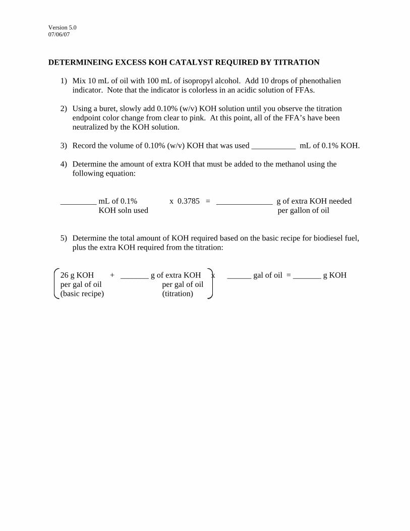
DETERMINEING EXCESS KOH CATALYST REQUIRED BY TITRATION
1) Mix 10 mL of oil with 100 mL of isopropyl alcohol. Add 10 drops of phenothalien indicator. Note that the indicator is colorless in an acidic solution of FFAs.
2) Using a buret, slowly add 0.10% (w/v) KOH solution until you observe the titration
endpoint color change from clear to pink. At this point, all of the FFA’s have been neutralized by the KOH solution.
3) Record the volume of 0.10% (w/v) KOH that was used ___________ mL of 0.1% KOH. 4) Determine the amount of extra KOH that must be added to the methanol using the
following equation:
_________ mL of 0.1% x 0.3785 = ______________ g of extra KOH needed
KOH soln used per gallon of oil
5) Determine the total amount of KOH required based on the basic recipe for biodiesel fuel, plus the extra KOH required from the titration:
26 g KOH + _______ g of extra KOH x ______ gal of oil = _______ g KOH per gal of oil per gal of oil (basic recipe) (titration)
Version 1.0 03/27/07
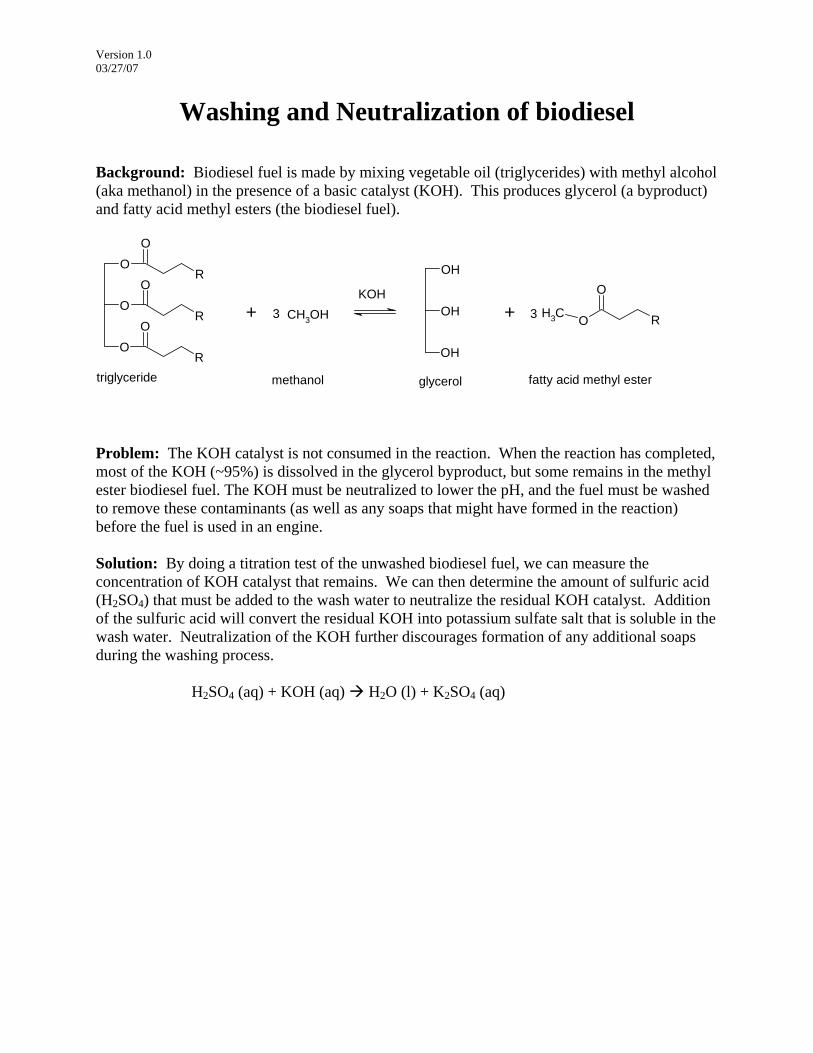
Washing and Neutralization of biodiesel Background: Biodiesel fuel is made by mixing vegetable oil (triglycerides) with methyl alcohol (aka methanol) in the presence of a basic catalyst (KOH). This produces glycerol (a byproduct) and fatty acid methyl esters (the biodiesel fuel).
OH
OH
OH
O R
O
CH3
OO
R
OO
R
OO
R
CH3OHKOH
+ +
triglyceride glycerol fatty acid methyl estermethanol
33
Problem: The KOH catalyst is not consumed in the reaction. When the reaction has completed, most of the KOH (~95%) is dissolved in the glycerol byproduct, but some remains in the methyl ester biodiesel fuel. The KOH must be neutralized to lower the pH, and the fuel must be washed to remove these contaminants (as well as any soaps that might have formed in the reaction) before the fuel is used in an engine. Solution: By doing a titration test of the unwashed biodiesel fuel, we can measure the concentration of KOH catalyst that remains. We can then determine the amount of sulfuric acid (H2SO4) that must be added to the wash water to neutralize the residual KOH catalyst. Addition of the sulfuric acid will convert the residual KOH into potassium sulfate salt that is soluble in the wash water. Neutralization of the KOH further discourages formation of any additional soaps during the washing process. H2SO4 (aq) + KOH (aq) H2O (l) + K2SO4 (aq)
Version 1.0 03/27/07
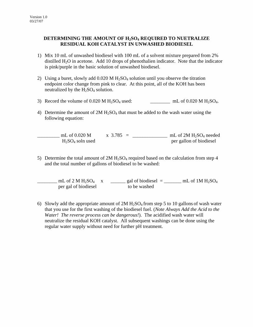
DETERMINING THE AMOUNT OF H2SO4 REQUIRED TO NUETRALIZE
RESIDUAL KOH CATALYST IN UNWASHED BIODIESEL
1) Mix 10 mL of unwashed biodiesel with 100 mL of a solvent mixture prepared from 2% distilled H2O in acetone. Add 10 drops of phenothalien indicator. Note that the indicator is pink/purple in the basic solution of unwashed biodiesel.
2) Using a buret, slowly add 0.020 M H2SO4 solution until you observe the titration
endpoint color change from pink to clear. At this point, all of the KOH has been neutralized by the H2SO4 solution.
3) Record the volume of 0.020 M H2SO4 used: ________ mL of 0.020 M H2SO4. 4) Determine the amount of 2M H2SO4 that must be added to the wash water using the
following equation:
_________ mL of 0.020 M x 3.785 = ______________ mL of 2M H2SO4 needed
H2SO4 soln used per gallon of biodiesel
5) Determine the total amount of 2M H2SO4 required based on the calculation from step 4 and the total number of gallons of biodiesel to be washed:
________ mL of 2 M H2SO4 x ______ gal of biodiesel = _______ mL of 1M H2SO4 per gal of biodiesel to be washed 6) Slowly add the appropriate amount of 2M H2SO4 from step 5 to 10 gallons of wash water
that you use for the first washing of the biodiesel fuel. (Note Always Add the Acid to the Water! The reverse process can be dangerous!). The acidified wash water will neutralize the residual KOH catalyst. All subsequent washings can be done using the regular water supply without need for further pH treatment.
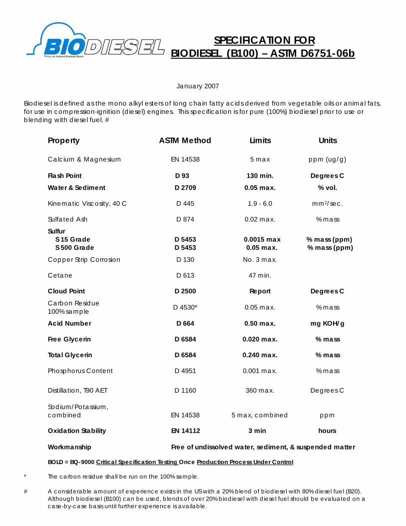
SPECIFICATION FOR
BIODIESEL (B100) – ASTM D6751-06b
January 2007
Biodiesel is defined as the mono alkyl esters of long chain fatty acids derived from vegetable oils or animal fats, for use in compression-ignition (diesel) engines. This specification is for pure (100%) biodiesel prior to use or blending with diesel fuel. #
Property ASTM Method Limits Units Calcium & Magnesium Flash Point
EN 14538
D 93
5 max
130 min.
ppm (ug/g)
Degrees C
Water & Sediment D 2709 0.05 max. % vol.
Kinematic Viscosity, 40 C D 445 1.9 - 6.0 mm2/sec.
Sulfated Ash D 874 0.02 max. % mass
Sulfur S 15 Grade S 500 Grade
D 5453 D 5453
0.0015 max 0.05 max.
% mass (ppm) % mass (ppm)
Copper Strip Corrosion D 130 No. 3 max.
Cetane D 613 47 min.
Cloud Point D 2500 Report Degrees C
Carbon Residue 100% sample D 4530* 0.05 max. % mass
Acid Number D 664 0.50 max. mg KOH/g
Free Glycerin D 6584 0.020 max. % mass
Total Glycerin D 6584 0.240 max. % mass
Phosphorus Content D 4951 0.001 max. % mass
Distillation, T90 AET D 1160 360 max. Degrees C
Sodium/Potassium, combined EN 14538 5 max, combined
ppm Oxidation Stability EN 14112 3 min hours
Workmanship Free of undissolved water, sediment, & suspended matter BOLD = BQ-9000 Critical Specification Testing Once Production Process Under Control
* The carbon residue shall be run on the 100% sample. # A considerable amount of experience exists in the US with a 20% blend of biodiesel with 80% diesel fuel (B20).
Although biodiesel (B100) can be used, blends of over 20% biodiesel with diesel fuel should be evaluated on a case-by-case basis until further experience is available.
Version 1.0 03/27/07
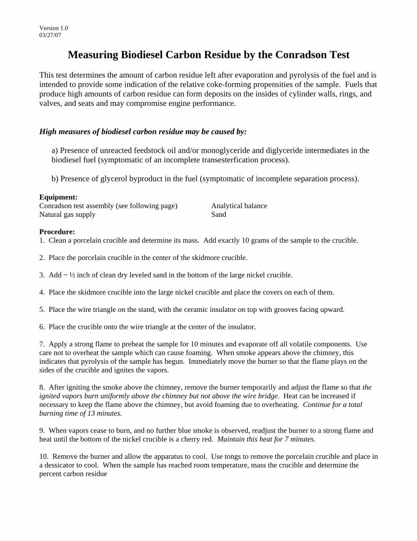
Measuring Biodiesel Carbon Residue by the Conradson Test This test determines the amount of carbon residue left after evaporation and pyrolysis of the fuel and is intended to provide some indication of the relative coke-forming propensities of the sample. Fuels that produce high amounts of carbon residue can form deposits on the insides of cylinder walls, rings, and valves, and seats and may compromise engine performance. High measures of biodiesel carbon residue may be caused by:
a) Presence of unreacted feedstock oil and/or monoglyceride and diglyceride intermediates in the biodiesel fuel (symptomatic of an incomplete transesterfication process). b) Presence of glycerol byproduct in the fuel (symptomatic of incomplete separation process).
Equipment: Conradson test assembly (see following page) Analytical balance Natural gas supply Sand Procedure: 1. Clean a porcelain crucible and determine its mass. Add exactly 10 grams of the sample to the crucible. 2. Place the porcelain crucible in the center of the skidmore crucible. 3. Add ~ ½ inch of clean dry leveled sand in the bottom of the large nickel crucible. 4. Place the skidmore crucible into the large nickel crucible and place the covers on each of them. 5. Place the wire triangle on the stand, with the ceramic insulator on top with grooves facing upward. 6. Place the crucible onto the wire triangle at the center of the insulator. 7. Apply a strong flame to preheat the sample for 10 minutes and evaporate off all volatile components. Use care not to overheat the sample which can cause foaming. When smoke appears above the chimney, this indicates that pyrolysis of the sample has begun. Immediately move the burner so that the flame plays on the sides of the crucible and ignites the vapors. 8. After igniting the smoke above the chimney, remove the burner temporarily and adjust the flame so that the ignited vapors burn uniformly above the chimney but not above the wire bridge. Heat can be increased if necessary to keep the flame above the chimney, but avoid foaming due to overheating. Continue for a total burning time of 13 minutes. 9. When vapors cease to burn, and no further blue smoke is observed, readjust the burner to a strong flame and heat until the bottom of the nickel crucible is a cherry red. Maintain this heat for 7 minutes. 10. Remove the burner and allow the apparatus to cool. Use tongs to remove the porcelain crucible and place in a dessicator to cool. When the sample has reached room temperature, mass the crucible and determine the percent carbon residue

Version 1.0 03/27/07
Cloud point measurement of biodiesel The cloud point of a fuel is the temperature at which solids (waxes) begin to cyrstalize in the fuel as it is cooled. Because the solidified particles can gel and clog the fuel filter, the cloud point is commonly used to determine the lowest temperature at which a fuel can be used during cold/winter conditions. Biodiesel has a higher cloud point than No. 2 diesel (that is, it begins to cloud/gel at higher temperatures), and so B100 (pure) biodiesel is not appropriate for cold weather applications. However, B20 biodiesel blends have a cloud point similar to No. 2 diesel. It is common to use cold weather additives in both No. 2 diesel and biodiesel blends in colder climates. The cloud point of biodiesel depends upon the feedstock used. In general, biodiesel produced from animal fats tends to have a higher cloud point than that produced from vegetable oil. Biodiesel from recycled waste oil products also tends to have a higher cloud point. Biodiesel contaminants such as un-reacted feedstock, monoglyceride and diglyceride intermediates, and residual free glycerol can also have adverse effects elevating the fuel’s cloud point. Materials & Equipment: Cloud point jar with biodiesel filled to the indicated line Thermometer (already in jar) Holder in ice bath Procedure: 1. Place the filled cloud point jar into the holder within the ice bath. 2. Observe the temperature indicated by the thermometer. Periodically remove the jar at intervals of roughly 3oC, and observe the biodiesel for any cloudiness (the biodiesel will begin to warm up when you remove it from the holder to replace it quickly if cloudiness is not apparent). 3. Record the temperature at which you observe the biodiesel to become cloudy. 4. Allow the biodiesel to warm up until the cloudiness clears, and then repeat for a total of 3 measurements. Take the average of these values and report this as your cloud point. Measurement #1: __________°F #2: __________°F #3: __________°F Average cloud point: __________°F

Version 1.0 03/27/07
Measuring the Corrosiveness of Biodiesel Fuel
Sulfur and other acidic/basic compounds in diesel fuels can have corrosive action on various metals (especially copper and brass which are often used in fuel line systems and). The copper strip test measures the relative corrosiveness of a fuel sample. Excessive copper corrosion may be caused by:
a) Presence of sulfur compounds in the fuel (possibly for biodiesel blends with petroleum). b) Presence of residual KOH catalyst in the biodiesel fuel (symptomatic of an incomplete neutralization/washing process). c) Presence of free fatty acids in the biodiesel fuel (symptomatic of aged fuel that has oxidized). d) Presence of water in the biodiesel fuel. Note that this will also be indicated by the centrifuge water and sediment test (symptomatic of an incomplete drying process).
Materials & Equipment: Copper strip (3” x ½” x 1/16”) Steel wool and ethanol to clean copper surface Constant temperature bath/block (50 oC) Reaction vessel with biodiesel fuel Procedure: 1. Clean the surface of the copper strip by polishing with steel wool. Use ethanol to help remove any oil deposits from your fingers. Verify the clean surface with a white cotton swab before proceeding. 2. Preheat a constant temperature bath/block to receive the sample chamber at 50 oC. 3. Immerse the copper strip in the sample chamber, seal and heat for 3 hours. 4. After 4 hours, remove the copper strips from the sample chamber. Clean the strip with ethanol and classify according to the following descriptions:
Slight Tarnish 1 a. Light orange, almost the same as freshly polished strip b. dark orange Moderate Tarnish 2 a. Claret red b. Lavendar c. Multicolored with lavender, blue, or silver overlaid on claret red d. Silvery e. Brassy or gold Dark Tarnish 3 a. Magenta Overcast on Brassy Strip b. Multicolored with red and green showing (peacock), but not gray Corrosion 4 a. Transparent black, grey, or brown with peacock green barely showing b. Graphite or lusterless black c. Glossy or jet black
Version 1.0 03/27/07
Measuring impurities and pH of biodiesel ASTM D6751 defines maximum limits in biodiesel for free glycerin (also called glycerol, a byproduct of the transesterification reaction) and for total glycerin (glycerol plus monoglyceride and diglyceride intermediates) impurities. Free glycerin in biodiesel can increase the biodiesel viscosity, settle at the bottom of storage tanks, and attract moisture. High total glycerin values can lead to carbon build-up and fuel system fouling in diesel engines. Measuring the glycerin content to ASTM standards requires access to either a gas chromatograph (GC) or a high performance liquid chromatograph (HPLC). This equipment is not commonly available outside of specialized chemical laboratories. However, qualitative indicator tests are commercially available to provide a quick assay for biodiesel glycerol content. The indicator test you will be using today will allow you to detect if any residual basic catalyst is present in the biodiesel and will provide a quick check of the fuels pH. An excessively high pH is caused by the presence of residual alkaline catalyst in the fuel. Alkaline biodiesel is corrosive to engine components and indicates that the fuel was not sufficiently washed. An excessively low pH may be caused by free fatty acids from the original feedstock oil, or by the aging (oxidation) of the biodiesel fuel over time. High acid numbers are associated with fuel system deposits, filter clogging and engine component corrosion. Materials & Equipment: pHLip test vial containing indicator solution Squeeze bulb ~10 – 15 mL biodiesel Procedure: 1. Transfer enough biodiesel into the test vial to almost fill the vial, leaving a small air space. 2. Tighten cap and gently flip the vial over 10 times. Allow contents to stand for 10 minutes (if you mix the biodiesel and indicator too vigorously, a much longer time will be necessary). The vial contents will separate into two layers: the top biodiesel layer and the bottom indicator layer. 3. Observe the top biodiesel layer: is it clear and bright or cloudy? 4. Observe the bottom indicator layer: is it clear or cloudy? What color is it (red, orange, yellow, purple)?
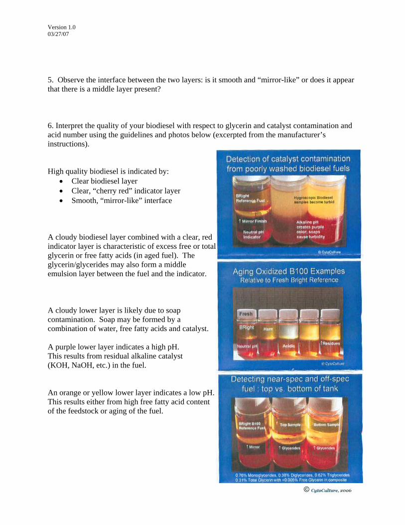
Version 1.0 03/27/07 5. Observe the interface between the two layers: is it smooth and “mirror-like” or does it appear that there is a middle layer present? 6. Interpret the quality of your biodiesel with respect to glycerin and catalyst contamination and acid number using the guidelines and photos below (excerpted from the manufacturer’s instructions). High quality biodiesel is indicated by:
• Clear biodiesel layer • Clear, “cherry red” indicator layer • Smooth, “mirror-like” interface
A cloudy biodiesel layer combined with a clear, red indicator layer is characteristic of excess free or total glycerin or free fatty acids (in aged fuel). The glycerin/glycerides may also form a middle emulsion layer between the fuel and the indicator. A cloudy lower layer is likely due to soap contamination. Soap may be formed by a combination of water, free fatty acids and catalyst. A purple lower layer indicates a high pH. This results from residual alkaline catalyst (KOH, NaOH, etc.) in the fuel. An orange or yellow lower layer indicates a low pH. This results either from high free fatty acid content of the feedstock or aging of the fuel.

Version 2.0 03/31/2007
Measuring Oxidative Stability By The Rancimat Test Over time, fuels can degrade by reaction with oxygen from the air. The rate at which biodiesel oxidizes depends on both the feedstock and processing conditions used to make the fuel. The oxidation process typically occurs over time scales of weeks to months, and is accelerated by factors such as aeration, light, and temperature. In some cases, the oxidation process may be slowed/inhibited through use of fuel additives (e.g. antioxidants, preservatives, etc.). The Rancimat oxidative stability test measures the rate at which biodiesel fuel decomposes when subjected to elevated temperatures and vigorous aeration. These conditions allow for a rapid measure of fuel stability that has been shown to correlate to the slower oxidative process that occurs under normal storage conditions. Preparing the Instrument Do this step a few days before the measurement is to be made:
1. Regenerate the intake air molecular sieve by removing the canister and heating it in a drying oven at 140–180 oC for 48 hours. 2. Inspect the intake air filter and replace if necessary.
Cleaning the Instrument The cleanness of instruments and accessories is an absolute necessity for achieving reliable, reproducible and correct analytical results. Even minute contamination can catalytically accelerate the oxidative decomposition and lead to completely false results.
1. Check whether the openings for the glass reaction tubes are clean and empty. Blow out any dust in the openings with nitrogen. Close the openings always with stoppers if the instrument is not used.
2. After the contents have been discarded clean used plastic conductivity measuring vessels several times with alcohol and distilled water (do not use acetone!).
3. Rinse the measuring vessel cover complete with electrodes and channels several times with distilled water. If necessary, remove the protective ring for better access to the electrodes.
4. Rinse the connection tubing between reaction tube and measuring vessel several times with distilled water and acetone.
5. It is recommended to use new glass reaction tubes and air tubes for each determination. Blow out new reaction tubes with nitrogen.
6. Used and not too strongly contaminated reaction tubes and air tubes can be cleaned by immersion in boiling RBS solution or a similar laboratory flushing agent for 1 h. They must then be thoroughly rinsed with distilled water and acetone. Note: RBS attacks glass. Reaction tubes and air tubes therefore cannot be cleaned ad infinitum.
7. Remove the air tube from the reaction tube cover and rinse it several times with distilled water and acetone. Dry the cover at 80°C in a drying oven.
8. Note: Reaction tube covers which have not been dried properly can falsify the results of the following determinations.
Version 2.0 03/31/2007
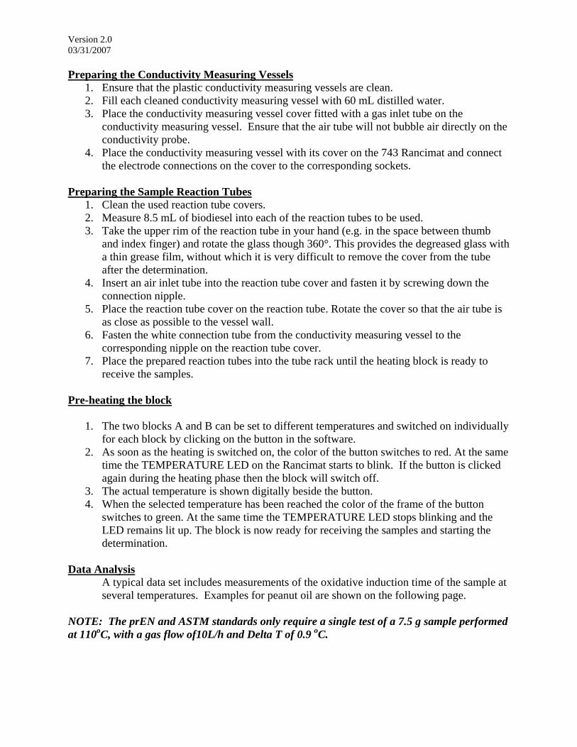
Preparing the Conductivity Measuring Vessels 1. Ensure that the plastic conductivity measuring vessels are clean. 2. Fill each cleaned conductivity measuring vessel with 60 mL distilled water. 3. Place the conductivity measuring vessel cover fitted with a gas inlet tube on the
conductivity measuring vessel. Ensure that the air tube will not bubble air directly on the conductivity probe.
4. Place the conductivity measuring vessel with its cover on the 743 Rancimat and connect the electrode connections on the cover to the corresponding sockets.
Preparing the Sample Reaction Tubes
1. Clean the used reaction tube covers. 2. Measure 8.5 mL of biodiesel into each of the reaction tubes to be used. 3. Take the upper rim of the reaction tube in your hand (e.g. in the space between thumb
and index finger) and rotate the glass though 360°. This provides the degreased glass with a thin grease film, without which it is very difficult to remove the cover from the tube after the determination.
4. Insert an air inlet tube into the reaction tube cover and fasten it by screwing down the connection nipple.
5. Place the reaction tube cover on the reaction tube. Rotate the cover so that the air tube is as close as possible to the vessel wall.
6. Fasten the white connection tube from the conductivity measuring vessel to the corresponding nipple on the reaction tube cover.
7. Place the prepared reaction tubes into the tube rack until the heating block is ready to receive the samples.
Pre-heating the block
1. The two blocks A and B can be set to different temperatures and switched on individually for each block by clicking on the button in the software.
2. As soon as the heating is switched on, the color of the button switches to red. At the same time the TEMPERATURE LED on the Rancimat starts to blink. If the button is clicked again during the heating phase then the block will switch off.
3. The actual temperature is shown digitally beside the button. 4. When the selected temperature has been reached the color of the frame of the button
switches to green. At the same time the TEMPERATURE LED stops blinking and the LED remains lit up. The block is now ready for receiving the samples and starting the determination.
Data Analysis
A typical data set includes measurements of the oxidative induction time of the sample at several temperatures. Examples for peanut oil are shown on the following page.
NOTE: The prEN and ASTM standards only require a single test of a 7.5 g sample performed at 110oC, with a gas flow of10L/h and Delta T of 0.9 oC.

Version 2.0 03/31/2007
Oxidative Stability and Induction Times for Peanut Oil at 130, 120, 110, and 100 C
Conductivity (uS/cm) versus time (hours)
Induction timeStability time
0.0 2.5 5.0 7.5 10.0 12.5
60.3
µS
/cm
h
Peanut oil / DBG2307 Peanut oil / DBG2307 Peanut oil / DBG2307 Peanut oil / DBG2307
Log-Linear Extrapolation of Oxidative Stability for Peanut oil
Temperature (C) versus Time (h)
10
20
30
40
50
60
70
80
90
100
110
120
130
140
101 102 103
°C
h

Version 1.0 03/27/07
Measuring the Kinematic Viscosity of Biodiesel Viscosity is an important factor in determining the suitability of biodiesel for use in engines. If the fuel viscosity is too high, the injection pump will not be able to supply sufficient fuel into the cylinder. If the viscosity is too low, it may provide insufficient lubrication for fuel pumps and injectors and in extreme cases, may cause fuel injector nozzles to leak/drip. High viscosity may be caused by:
a) Presence of unreacted feedstock oil and/or monoglyceride and diglyceride intermediates in the biodiesel fuel (symptomatic of an incomplete transesterfication process). b) Presence of glycerol byproduct in the biodiesel fuel (symptomatic of incomplete separation process).
Low viscosity may be caused by:
a) Presence of methanol in the biodiesel fuel. Note that this will also be indicated by a low fuel flashpoint (symptomatic of an incomplete washing process). b) Presence of water in the biodiesel fuel. Note that this will also be indicated by the centrifuge water and sediment test (symptomatic of an incomplete drying process).
There are two types of viscosity: kinematic viscosity measures the resistance of a liquid to flowing under gravity and has units of mm2/s; dynamic viscosity is the ratio of the applied shear stress to the rate of shear of a material and has units of mPa·s, or more commonly centipoise (1 mPa·s = 1 cP). The kinematic and dynamic viscosity of a fluid are related by its density. The density of biodiesel is about 0.88 g/cm3. Kinematic viscosity (in mm2/s) = dynamic viscosity (in cP) ÷ density (in g/cm3) The viscometer you will be using measures the dynamic viscosity of fluids, but the ASTM 6751 standard for B100 (pure biodiesel) specifies a kinematic viscosity in the range of 1.9 – 6.0 mm2/s at 40°C (104°F). At this lab station you will measure the dynamic viscosity of your biodiesel and use the equation above or the attached table to convert its dynamic viscosity value to a kinematic viscosity value. Materials & Equipment: VT 01 Viscotester viscometer Hot Plate + water bath Digital thermometer ~ 400 mL biodiesel

Version 1.0 03/27/07 Procedure: 1. Place the probe tip of the digital thermometer into the biodiesel in the viscometer sample cup. The temperature should read between 39°C and 41°C. If it does not, slightly adjust the setting on the hot plate and wait a few minutes for the temperature to change. 2. When the biodiesel is in the desired temperature range, REMOVE the thermometer from the sample cup and set aside. 3. Turn on the viscometer by flipping the main switch into the “on” position. This switch is silver and located at the end of the viscometer opposite the indicator scales. 4. Once the indicator needle has stabilized, read the dynamic viscosity from scale bar #4 (top scale bar), which displays dynamic viscosity values from 1.5 – 33 cP, and record this value. Dynamic viscosity measured with VT 01 viscometer: ____________________ cP Kinematic viscosity (in mm2/s) = dynamic viscosity (in cP) ÷ density (in g/cm3) = _______________ cP ÷ 0.88 g/cm3 = ______________ mm2/s OR use the table below to find the nearest dynamic viscosity value to the one you measured and read across to find the corresponding kinematic viscosity value and record it above.
Dynamic viscosity Density of Biodiesel Kinematic Viscosity( meter measures mPa*s aka cP) (g/cm3) (mm2/s)
1.00 0.88 1.141.50 0.88 1.701.75 0.88 1.992.00 0.88 2.272.50 0.88 2.843.00 0.88 3.413.50 0.88 3.984.00 0.88 4.554.50 0.88 5.115.00 0.88 5.685.25 0.88 5.975.50 0.88 6.256.00 0.88 6.826.50 0.88 7.397.00 0.88 7.957.50 0.88 8.528.00 0.88 9.098.50 0.88 9.669.00 0.88 10.239.50 0.88 10.80
10.00 0.88 11.36 The uncertainty of the dynamic viscosity measurement is +/- 10% of the full scale, or ~ 3 cP. This corresponds to an uncertainty of about +/- 3.5 mm2/s in the kinematic viscosity calculation. Is your kinematic viscosity value within the ASTM specification of 1.9 – 6.0 mm2/s ? If not, what processing conditions might have caused your fuel to be off-spec?

Version 1.0 03/27/07
Measuring the Water and Sediment present in Biodiesel Fuel
Water and sediment can cause problems with fuel line icing and filter plugging. In order to meet ASTM specifications, biodiesel must contain < 0.050% water and sediment by volume. Failure to meet this specification usually is attributable to poor separation processes during the biodiesel synthesis or washing stages. Materials & Equipment: Centrifuge, Centrifuge tubes, biodiesel fuel Procedure: 1. Check all of the slots available on the centrifuge and inspect for the presence of weights or stoppers in the bottom of the slots. It is critical to ensure that the centrifuge rotor is balanced. 2. Obtain two matched centrifuge tubes of similar manufacture (same shape, mass, etc.) Fill both tubes with equal quantities of biodiesel so that they contain an equal mass of fuel. 3. Place the tubes in centrifuge slots located directly opposite one another to maintain balance on the rotor. 4. Spin the samples at 800 rcf (relative centrifugal force) for a period of 10 minutes. 5. When the centrifuge has stopped, remove the tubes and report the % water and sediment. Note: ASTM D2709 requires specialized centrifuge tubes to obtain the desired accuracy for this test. If performing the test to these standards, the taper bottom tubes must accommodate 100 mL fuel samples and be marked with graduations to the nearest 0.01 mL.

Lisitng of Biodiesel Fuel Tests and Standard Test Methods
Property Test Method Apparatus/Procedure units limits measured
value result
Water and sediment D2709 centifuge % vol .050 max pass or fail
Carbon Residue (10 g sample) D4530 Conradson flame test % mass .050 max pass or fail
FlashPoint, closed cup D93 Pensky Martens Flash Cup oC 130 min pass or fail
Kinematic Viscosity (at 40 oC) D445 Viscometer mm2/sec 1.9-6.0 pass or fail
Oxidative Stability (at 110 oC) prEN 14112 Rancimat hrs 3 hrs min. pass or fail
Copper Strip Corrosion D130 Copper strips and heater class No 3. max pass or fail
Free and Total glycerin pHLip pHLip assay NA Haze or emulsion yes or no pass or fail
FFA (pH) pHLip pHLip assay NA yellow indicator yes or no pass or fail
Residual Catalyst (pH) pHLip pHLip assay NA purple indicator yes or no pass or fail
Specific gravity D1250 hygrometer NA report NA
Cloud Point D2500 cloud point bath oC report NA
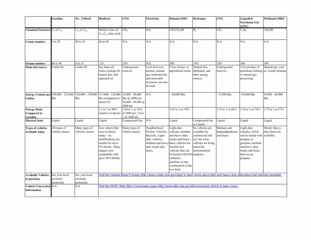
Gasoline No. 2 Diesel Biodiesel CNG Electricity Ethanol (E85) Hydrogen LNG Liquefied Petroleum Gas (LPG)
Methanol (M85)
Chemical Structure C4 to C12 C10 to C20 Methyl esters of C16-C18 fatty acids
CH4 N/A CH3CH2OH H2 CH4 C3H8 CH3OH
Cetane number 5 to 20 40 to 55 46 to 60 N/A N/A N/A N/A N/A N/A N/A
Octane number 86 to 94 8 to 15 ~25 120+ N/A 100 130+ 120+ 104 100Main fuel source Crude Oil Crude Oil Soy bean oil,
waste cooking oil, animal fats, and rapeseed oil
Underground reserves
Coal; however, nuclear, natural gas, hydroelectric, and renewable resources can also be used.
Corn, Grains, or agricultural waste
Natural Gas, Methanol, and other energy sources
Underground reserves
A by-product of petroleum refining or natural gas processing
Natural gas, coal, or, woody biomass
Energy Content per Gallon
109,000 - 125,000 Btu
128,000 - 130,000 Btu
117,000 - 120,000 Btu (compared to diesel #2)
33,000 - 38,000 Btu @ 3000 psi; 38,000 - 44,000 @ 3600 psi
N/A ~ 80,000 Btu ~73,500 Btu ~84,000 Btu 56,000 - 66,000 Btu
Energy Ratio Compared to Gasoline
1.1 to 1 or 90% (relative to diesel)
3.94 to 1 or 25% at 3000 psi; 3.0 to 1 @ 3600 psi
1.42 to 1 or 70% 1.55 to 1 or 66% 1.36 to 1 or 74% 1.75 to 1 or 57%
Physical State Liquid Liquid Liquid Compressed Gas N/A Liquid Compressed Gas or Liquid
Liquid Liquid Liquid
Types of vehicles available today
All types of vehicle classes.
Many types of vehicles classes.
Any vehicle that runs on diesel today—no modifications are needed for up to 5% blends. Many engines also compatible with up to 20% blends.
Many types of vehicle classes.
Neighborhood Electric Vehicles, Bicycles, Light-duty vehicles, medium and heavy-duty trucks and buses.
Light-duty vehicles, medium and heavy-duty trucks and buses - these vehicles are flexible fuel vehicles that can be fueled with E85 (ethanol), gasoline, or any combination of the two fuels.
No vehicles are available for commercial sale yet, but some vehicles are being leased for demonstration purposes.
Medium and heavy-duty trucks and buses.
Light-duty vehicles, which can be fueled with propane or gasoline, medium and heavy-duty trucks and buses that run on propane.
Mostly Heavy-duty buses are available.
Available Vehicles to purchase
See your local car/truck dealership
See your local car/truck dealership
Vehicle Conversion Information
N/A N/A
Visit the Vehicle Buyer’s Guide (http://www.ccities.doe.gov/vbg/) to learn more about light and heavy-duty alternative fuel vehicles available
Visit the AFDC Web Site’s Conversion page (http://www.afdc.doe.gov/afv/conversion.shtml) to learn more.
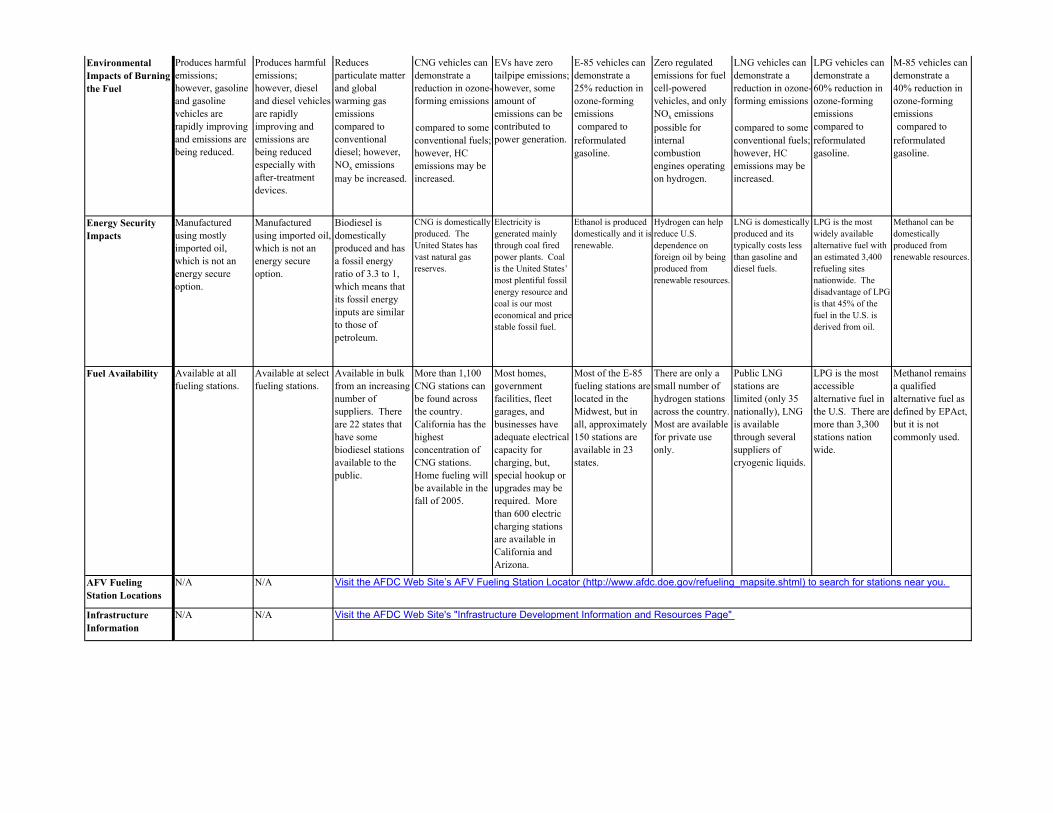
Environmental Impacts of Burning the Fuel
Produces harmful emissions; however, gasoline and gasoline vehicles are rapidly improving and emissions are being reduced.
Produces harmful emissions; however, diesel and diesel vehicles are rapidly improving and emissions are being reduced especially with after-treatment devices.
Reduces particulate matter and global warming gas emissions compared to conventional diesel; however, NOx emissions may be increased.
CNG vehicles can demonstrate a reduction in ozone-forming emissions
compared to some conventional fuels; however, HC emissions may be increased.
EVs have zero tailpipe emissions; however, some amount of emissions can be contributed to power generation.
E-85 vehicles can demonstrate a 25% reduction in ozone-forming emissions compared to reformulated gasoline.
Zero regulated emissions for fuel cell-powered vehicles, and only NOx emissions possible for internal combustion engines operating on hydrogen.
LNG vehicles can demonstrate a reduction in ozone-forming emissions
compared to some conventional fuels; however, HC emissions may be increased.
LPG vehicles can demonstrate a 60% reduction in ozone-forming emissions compared to reformulated gasoline.
M-85 vehicles can demonstrate a 40% reduction in ozone-forming emissions compared to reformulated gasoline.
Energy Security Impacts
Manufactured using mostly imported oil, which is not an energy secure option.
Manufactured using imported oil, which is not an energy secure option.
Biodiesel is domestically produced and has a fossil energy ratio of 3.3 to 1, which means that its fossil energy inputs are similar to those of petroleum.
CNG is domestically produced. The United States has vast natural gas reserves.
Electricity is generated mainly through coal fired power plants. Coal is the United States’ most plentiful fossil energy resource and coal is our most economical and pricestable fossil fuel.
Ethanol is produced domestically and it is renewable.
Hydrogen can help reduce U.S. dependence on foreign oil by being produced from renewable resources.
LNG is domestically produced and its typically costs less than gasoline and diesel fuels.
LPG is the most widely available alternative fuel with an estimated 3,400 refueling sites nationwide. The disadvantage of LPG is that 45% of the fuel in the U.S. is derived from oil.
Methanol can be domestically produced from renewable resources.
Fuel Availability Available at all fueling stations.
Available at select fueling stations.
Available in bulk from an increasing number of suppliers. There are 22 states that have some biodiesel stations available to the public.
More than 1,100 CNG stations can be found across the country. California has the highest concentration of CNG stations. Home fueling will be available in the fall of 2005.
Most homes, government facilities, fleet garages, and businesses have adequate electrical capacity for charging, but, special hookup or upgrades may be required. More than 600 electric charging stations are available in California and Arizona.
Most of the E-85 fueling stations are located in the Midwest, but in all, approximately 150 stations are available in 23 states.
There are only a small number of hydrogen stations across the country. Most are available for private use only.
Public LNG stations are limited (only 35 nationally), LNG is available through several suppliers of cryogenic liquids.
LPG is the most accessible alternative fuel in the U.S. There are more than 3,300 stations nation wide.
Methanol remains a qualified alternative fuel as defined by EPAct, but it is not commonly used.
AFV Fueling Station Locations
N/A N/A
Infrastructure Information
N/A N/A Visit the AFDC Web Site's "Infrastructure Development Information and Resources Page"
Visit the AFDC Web Site’s AFV Fueling Station Locator (http://www.afdc.doe.gov/refueling_mapsite.shtml) to search for stations near you.

Maintenance Issues Hoses and seals may be affected with higher-percent blends, lubricity is improved over that of conventional diesel fuel.
High-pressure tanks require periodic inspection and certification.
Service requirements are expected to be reduced. No tune-ups, oil changes, timing belts, water pumps, radiators, or fuel injectors are required. However, the batteries must be replaced every 3-6 years.
Special lubricants may be required. Practices are very similar, if not identical, to those for conventionally fueled operations.
When hydrogen is used in fuel cell applications, maintenance should be very minimal.
High-pressure tanks require periodic inspection and certification.
Some fleets report service lives that are 2-3 years longer, as well as extended intervals between required maintenance.
Special lubricants must be used as directed by the supplier and M-85-compatible replacement parts must be used.
Safety (Without exception, all alternative fuel vehicles must meet today's OEM safety standards)
Gasoline is a relatively safe fuel since people have learned to use it safely. Gasoline is not biodegradable though, so a spill could pollute soil and water.
Diesel is a relatively safe fuel since people have learned to use it safely. Diesel is not biodegradable though, so a spill could pollute soil and water.
Less toxic and more biodegradable than conventional fuel, can be transported, delivered, and stored using the same equipment as for diesel fuel.
Pressurized tanks have been designed to withstand severe impact, high external temperatures, and automotive environmental exposure.
OEM EVs meet all the same vehicle safety standards as conventional vehicles.
Ethanol can form an explosive vapor in fuel tanks. In accidents; however, ethanol is less dangerous than gasoline because its low evaporation speed keeps alcohol concentration in the air low and non explosive.
Hydrogen has an excellent industrial safety record; codes and standards for consumer vehicle use are under development.
Cryogenic fuels require special handling procedures and equipment to properly store and dispense.
Adequate ventilation is important for fueling an LPG vehicle due to increased flammability of LPG. LPG tanks are 20 times more puncture resistant than gasoline tanks and can withstand high impact.
Methanol can form an explosive vapor in fuel tanks. In accidents; however, methanol is less dangerous than gasoline because its low evaporation speed keeps alcohol concentration in the air low and non explosive.
Average Cost/gge You can get average costs for all fuel types through the Alternative Fuel Price Report (www.afdc.doe.gov/documents/pricereport/pricereports.html)