Embed Size (px)
Citation preview
BME/ECE 386 Lab 1 Load Cell Measurement System
1
Lab 1 – Load Cell Measurement System
GOALS
1) Build and test a load cell amplifier.
2) Write an Arduino program to:
a. Acquire data from a load cell amplifier
b. Compute load in grams
c. Send the data to a computer using the serial port.
3) Perform some fun experiments with your load cell measurement system!
GENERAL GUIDELINES
1) Each student must build his/her own circuit.
2) Due to the limited number of test stations, some students need to pair up and share the test equipment.
3) Students are encouraged to help each other. Of course, Buma will be around to provide assistance as well.
4) Do not worry if you need lots of help during the lecture and lab activities. Just make sure you know your stuff for the exams. In addition to the written exams, there will be one lab practical where each student is tested on putting together a complete measurement system (circuit construction, Arduino + MATLAB programming).
5) Ask questions! The more questions you ask, the more you learn!
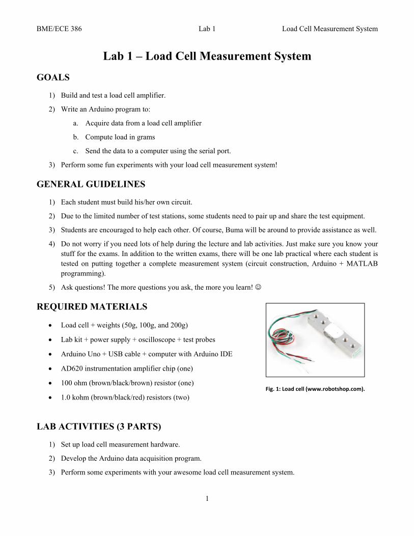
REQUIRED MATERIALS
Load cell + weights (50g, 100g, and 200g)
Lab kit + power supply + oscilloscope + test probes
Arduino Uno + USB cable + computer with Arduino IDE
AD620 instrumentation amplifier chip (one)
100 ohm (brown/black/brown) resistor (one)
1.0 kohm (brown/black/red) resistors (two)
LAB ACTIVITIES (3 PARTS)
1) Set up load cell measurement hardware.
2) Develop the Arduino data acquisition program.
3) Perform some experiments with your awesome load cell measurement system.
Fig. 1: Load cell (www.robotshop.com).
BME/ECE 386 Lab 1 Load Cell Measurement System
2
INTRODUCTION
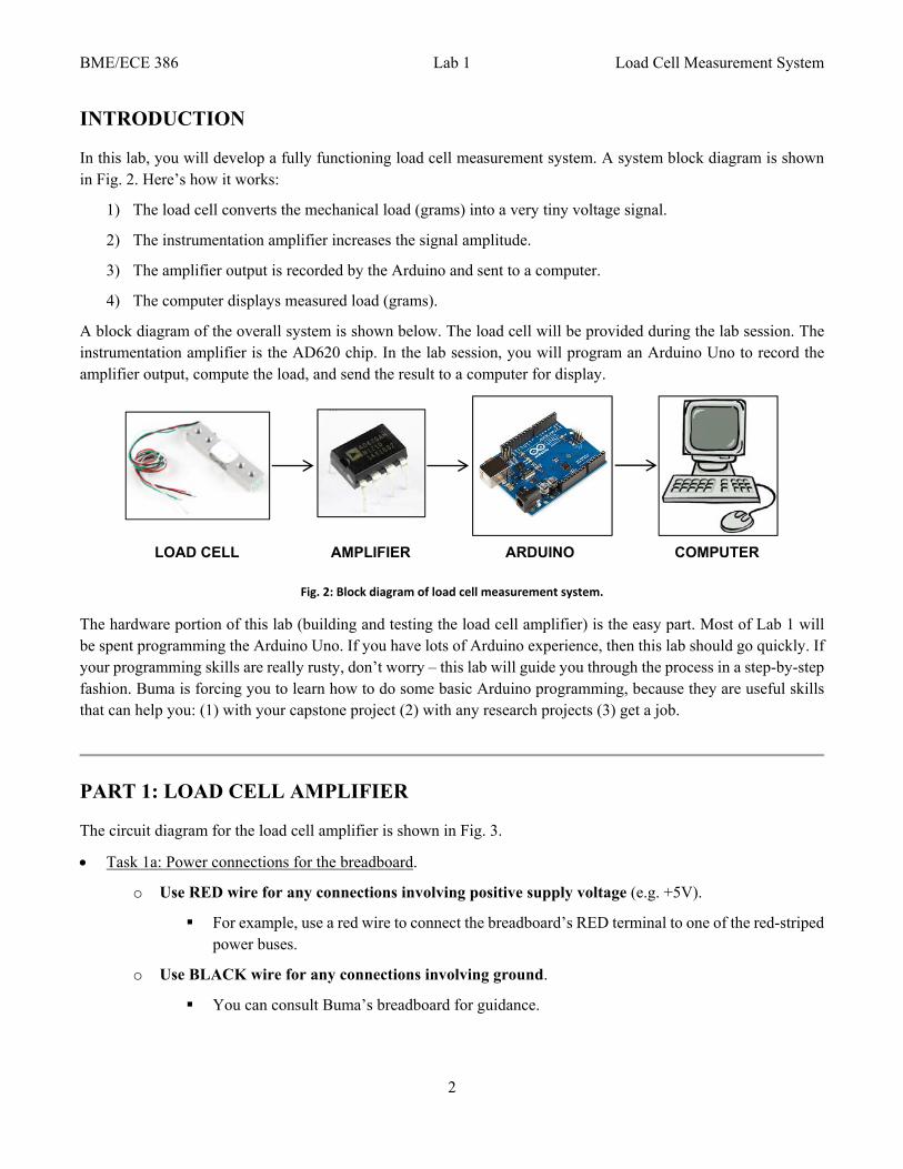
In this lab, you will develop a fully functioning load cell measurement system. A system block diagram is shown in Fig. 2. Here’s how it works:
1) The load cell converts the mechanical load (grams) into a very tiny voltage signal.
2) The instrumentation amplifier increases the signal amplitude.
3) The amplifier output is recorded by the Arduino and sent to a computer.
4) The computer displays measured load (grams).
A block diagram of the overall system is shown below. The load cell will be provided during the lab session. The instrumentation amplifier is the AD620 chip. In the lab session, you will program an Arduino Uno to record the amplifier output, compute the load, and send the result to a computer for display.
Fig. 2: Block diagram of load cell measurement system.
The hardware portion of this lab (building and testing the load cell amplifier) is the easy part. Most of Lab 1 will be spent programming the Arduino Uno. If you have lots of Arduino experience, then this lab should go quickly. If your programming skills are really rusty, don’t worry – this lab will guide you through the process in a step-by-step fashion. Buma is forcing you to learn how to do some basic Arduino programming, because they are useful skills that can help you: (1) with your capstone project (2) with any research projects (3) get a job.
PART 1: LOAD CELL AMPLIFIER
The circuit diagram for the load cell amplifier is shown in Fig. 3.
Task 1a: Power connections for the breadboard.
o Use RED wire for any connections involving positive supply voltage (e.g. +5V).
For example, use a red wire to connect the breadboard’s RED terminal to one of the red-striped power buses.
o Use BLACK wire for any connections involving ground.
You can consult Buma’s breadboard for guidance.
LOAD CELL AMPLIFIER ARDUINO COMPUTER
BME/ECE 386 Lab 1 Load Cell Measurement System
3
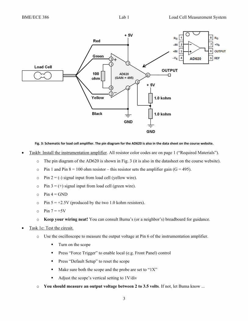
Fig. 3: Schematic for load cell amplifier. The pin diagram for the AD620 is also in the data sheet on the course website.
Taskb: Install the instrumentation amplifier. All resistor color codes are on page 1 (“Required Materials”).
o The pin diagram of the AD620 is shown in Fig. 3 (it is also in the datasheet on the course website).
o Pin 1 and Pin 8 = 100 ohm resistor – this resistor sets the amplifier gain (G = 495).
o Pin 2 = (-) signal input from load cell (yellow wire).
o Pin 3 = (+) signal input from load cell (green wire).
o Pin 4 = GND
o Pin 5 = +2.5V (produced by the two 1.0 kohm resistors).
o Pin 7 = +5V
o Keep your wiring neat! You can consult Buma’s (or a neighbor’s) breadboard for guidance.
Task 1c: Test the circuit.
o Use the oscilloscope to measure the output voltage at Pin 6 of the instrumentation amplifier.
Turn on the scope
Press “Force Trigger” to enable local (e.g. Front Panel) control
Press “Default Setup” to reset the scope
Make sure both the scope and the probe are set to “1X”
Adjust the scope’s vertical setting to 1V/div
o You should measure an output voltage between 2 to 3.5 volts. If not, let Buma know ...
BME/ECE 386 Lab 1 Load Cell Measurement System
4
o Place a 200g weight on the gray platform of the load cell – the voltage should increase by ≈ 0.5V.
o If you are having difficulties getting your load cell amplifier to work properly, feel free to ask Buma or the lab assistant for help.
(End of Part 1)
PART 2: ARDUINO WARM-UP EXERCISES
Buma will assume that your Arduino skills have somewhat faded since ESC100. Therefore, we’ll do three quick exercises to remind ourselves how to use an Arduino.
The Arduino board is programmed using the “Arduino IDE”, where IDE stands for “Integrated Development Environment”. An Arduino program is called a “sketch”. Buma has kindly provided a sketch “template” for you to get started.
Download and unzip the Arduino template.
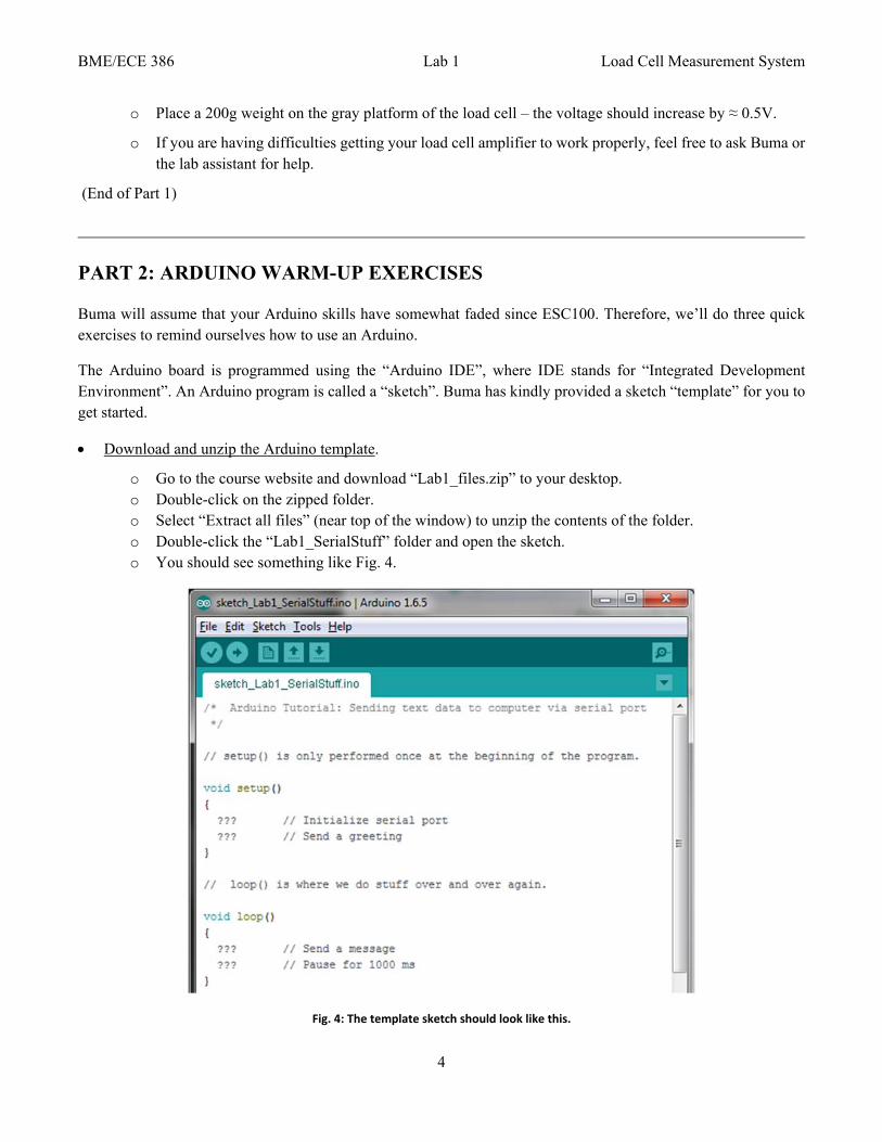
o Go to the course website and download “Lab1_files.zip” to your desktop. o Double-click on the zipped folder. o Select “Extract all files” (near top of the window) to unzip the contents of the folder. o Double-click the “Lab1_SerialStuff” folder and open the sketch. o You should see something like Fig. 4.
Fig. 4: The template sketch should look like this.
BME/ECE 386 Lab 1 Load Cell Measurement System
5
EXERCISE 2.1
Our first Arduino exercise is to send simple messages to the computer via the serial port. How to do this?
Any Arduino program requires a setup( ) routine and loop( ) routine.
Fig. 5 is the flow chart for the Exercise 2.1 program.
(a) Setup routine (runs only ONCE)
o Initialize the serial port
o Send a greeting
(b) Loop routine (runs over and over again)
o Send a message
o Wait 1000 ms
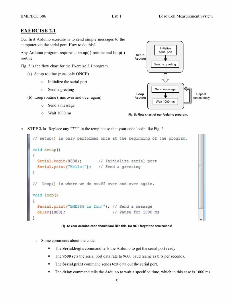
o STEP 2.1a: Replace any “???” in the template so that your code looks like Fig. 6.
Fig. 6: Your Arduino code should look like this. Do NOT forget the semicolons!
o Some comments about the code:
The Serial.begin command tells the Arduino to get the serial port ready.
The 9600 sets the serial port data rate to 9600 baud (same as bits per second).
The Serial.print command sends text data out the serial port.
The delay command tells the Arduino to wait a specified time, which in this case is 1000 ms.
Send a greeting
Wait 1000 ms
Send message
Initialize serial port
Repeat continuously
Setup Routine
Loop Routine
Fig. 5: Flow chart of our Arduino program.
BME/ECE 386 Lab 1 Load Cell Measurement System
6
o STEP 2.1b: Compile and upload the code.
An Arduino sketch needs to be converted to “machine” code that is understandable to the microcontroller. Once the code is compiled, it needs to be transferred to the board.
o Compile the code WITHOUT uploading to the board.
At the top of the sketch window, go to Tools >> Board.
Make sure Arduino/Genuino Uno is selected.
If the wrong board is selected, your code won’t work on the Uno!
Click on the “check-mark” button in the top left corner (Fig. 7).
The bottom of the Arduino screen will say “Compiling sketch ...”
If no error occurs, it will eventually say “Done compiling”.
If an error occurs, it will tell you the problem.
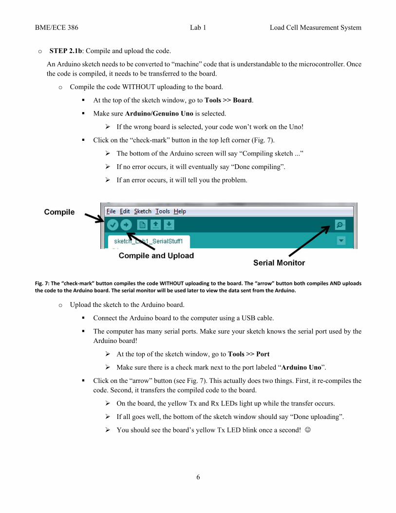
Fig. 7: The “check‐mark” button compiles the code WITHOUT uploading to the board. The “arrow” button both compiles AND uploads the code to the Arduino board. The serial monitor will be used later to view the data sent from the Arduino.
o Upload the sketch to the Arduino board.
Connect the Arduino board to the computer using a USB cable.
The computer has many serial ports. Make sure your sketch knows the serial port used by the Arduino board!
At the top of the sketch window, go to Tools >> Port
Make sure there is a check mark next to the port labeled “Arduino Uno”.
Click on the “arrow” button (see Fig. 7). This actually does two things. First, it re-compiles the code. Second, it transfers the compiled code to the board.
On the board, the yellow Tx and Rx LEDs light up while the transfer occurs.
If all goes well, the bottom of the sketch window should say “Done uploading”.
You should see the board’s yellow Tx LED blink once a second!
BME/ECE 386 Lab 1 Load Cell Measurement System
7
o STEP 2.1c: Observe the Arduino data using the Serial Monitor on the computer.
o Click on the top right button (looks like a magnifying glass) in the Arduino IDE (Fig. 7).
Make sure the bottom right corner of the Serial Monitor says 9600 baud.
Otherwise, the monitor will display some interesting looking characters.
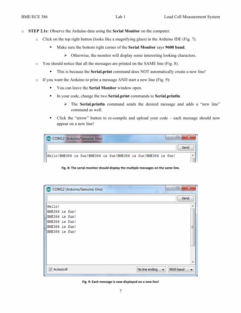
o You should notice that all the messages are printed on the SAME line (Fig. 8).
This is because the Serial.print command does NOT automatically create a new line!
o If you want the Arduino to print a message AND start a new line (Fig. 9):
You can leave the Serial Monitor window open.
In your code, change the two Serial.print commands to Serial.println.
The Serial.println command sends the desired message and adds a “new line” command as well.
Click the “arrow” button to re-compile and upload your code – each message should now appear on a new line!
Fig. 8: The serial monitor should display the multiple messages on the same line.
Fig. 9: Each message is now displayed on a new line!
BME/ECE 386 Lab 1 Load Cell Measurement System
8
EXERCISE 2.2
Now let’s do a simple computation and send the result to the computer. We want the Arduino to act like a timer and display the number of seconds. A simple way to do this is to create a new variable T that keeps track of time. The value of T is updated at the end of each loop iteration.
o STEP 2.2a: Revise the loop( ) routine so that your code looks like Fig. 10. Don’t forget to add the line of code just before the loop! Also don’t forget the semicolons!
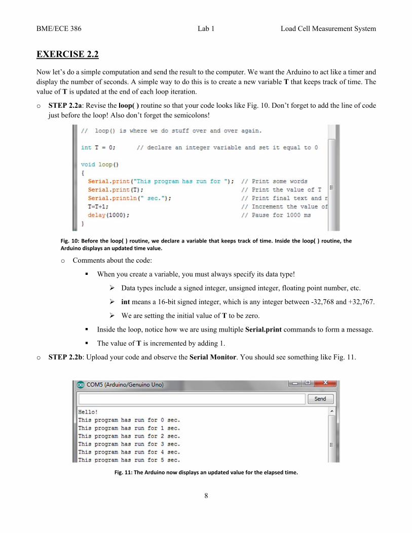
Fig. 10: Before the loop( ) routine, we declare a variable that keeps track of time. Inside the loop( ) routine, the Arduino displays an updated time value.
o Comments about the code:
When you create a variable, you must always specify its data type!
Data types include a signed integer, unsigned integer, floating point number, etc.
int means a 16-bit signed integer, which is any integer between -32,768 and +32,767.
We are setting the initial value of T to be zero.
Inside the loop, notice how we are using multiple Serial.print commands to form a message.
The value of T is incremented by adding 1.
o STEP 2.2b: Upload your code and observe the Serial Monitor. You should see something like Fig. 11.
Fig. 11: The Arduino now displays an updated value for the elapsed time.
BME/ECE 386 Lab 1 Load Cell Measurement System
9
EXERCISE 2.3
This is the last warm-up exercise! Let’s record a voltage and send the result to the computer.
The flow chart of our program looks like Fig. 12.
(a) Setup routine
o Initialize serial port
o Send a greeting
(b) Loop routine
o Record ADC output
o Compute voltage
o Send data via serial port
o Wait 1 sec
o STEP 2.3a: Revise the loop( ) routine so that your code looks like Fig. 13.
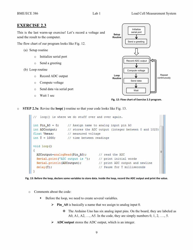
Fig. 13: Before the loop, declare some variables to store data. Inside the loop, record the ADC output and print the value.
o Comments about the code:
Before the loop, we need to create several variables.
Pin_A0 is basically a name that we assign to analog input 0.
The Arduino Uno has six analog input pins. On the board, they are labeled as A0, A1, A2, …, A5. In the code, they are simply numbers 0, 1, 2, …., 5.
ADCoutput stores the ADC output, which is an integer.
Fig. 12: Flow chart of Exercise 2.3 program.
Send a greeting
Wait
Record ADC output
Initialize serial port
Repeat continuously
Setup Routine
Loop Routine
Compute voltage
Send data
BME/ECE 386 Lab 1 Load Cell Measurement System
10
Vmeas is a floating point number (e.g. has decimal point) to store the measured voltage.
T is the number of milliseconds to wait between analog readings.
Inside the loop, we must do several things:
analogRead reads the ADC output from Pin_A0.
For now, we will simply print the ADCoutput value.
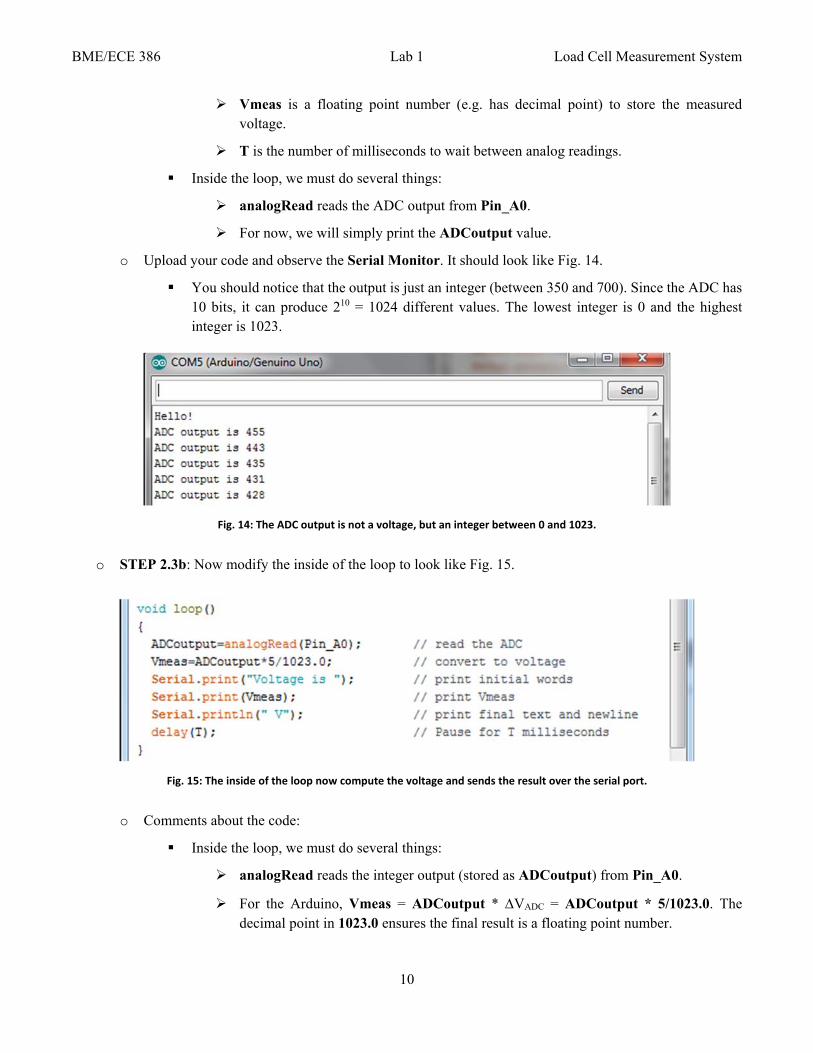
o Upload your code and observe the Serial Monitor. It should look like Fig. 14.
You should notice that the output is just an integer (between 350 and 700). Since the ADC has 10 bits, it can produce 210 = 1024 different values. The lowest integer is 0 and the highest integer is 1023.
Fig. 14: The ADC output is not a voltage, but an integer between 0 and 1023.
o STEP 2.3b: Now modify the inside of the loop to look like Fig. 15.
Fig. 15: The inside of the loop now compute the voltage and sends the result over the serial port.
o Comments about the code:
Inside the loop, we must do several things:
analogRead reads the integer output (stored as ADCoutput) from Pin_A0.
For the Arduino, Vmeas = ADCoutput * VADC = ADCoutput * 5/1023.0. The decimal point in 1023.0 ensures the final result is a floating point number.
BME/ECE 386 Lab 1 Load Cell Measurement System
11
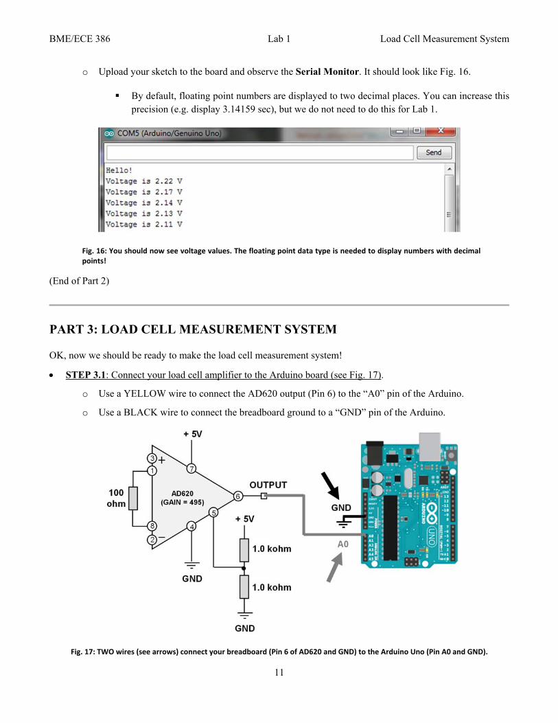
o Upload your sketch to the board and observe the Serial Monitor. It should look like Fig. 16.
By default, floating point numbers are displayed to two decimal places. You can increase this precision (e.g. display 3.14159 sec), but we do not need to do this for Lab 1.
Fig. 16: You should now see voltage values. The floating point data type is needed to display numbers with decimal points!
(End of Part 2)
PART 3: LOAD CELL MEASUREMENT SYSTEM
OK, now we should be ready to make the load cell measurement system!
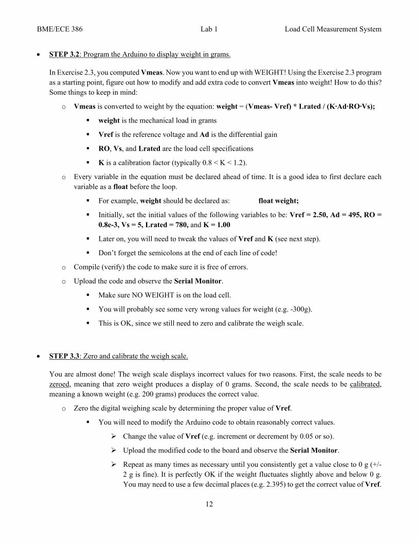
STEP 3.1: Connect your load cell amplifier to the Arduino board (see Fig. 17).
o Use a YELLOW wire to connect the AD620 output (Pin 6) to the “A0” pin of the Arduino.
o Use a BLACK wire to connect the breadboard ground to a “GND” pin of the Arduino.
Fig. 17: TWO wires (see arrows) connect your breadboard (Pin 6 of AD620 and GND) to the Arduino Uno (Pin A0 and GND).
BME/ECE 386 Lab 1 Load Cell Measurement System
12
STEP 3.2: Program the Arduino to display weight in grams.
In Exercise 2.3, you computed Vmeas. Now you want to end up with WEIGHT! Using the Exercise 2.3 program as a starting point, figure out how to modify and add extra code to convert Vmeas into weight! How to do this? Some things to keep in mind:
o Vmeas is converted to weight by the equation: weight = (Vmeas- Vref) * Lrated / (K∙Ad∙RO∙Vs);
weight is the mechanical load in grams
Vref is the reference voltage and Ad is the differential gain
RO, Vs, and Lrated are the load cell specifications
K is a calibration factor (typically 0.8 < K < 1.2).
o Every variable in the equation must be declared ahead of time. It is a good idea to first declare each variable as a float before the loop.
For example, weight should be declared as: float weight;
Initially, set the initial values of the following variables to be: Vref = 2.50, Ad = 495, RO = 0.8e-3, Vs = 5, Lrated = 780, and K = 1.00
Later on, you will need to tweak the values of Vref and K (see next step).
Don’t forget the semicolons at the end of each line of code!
o Compile (verify) the code to make sure it is free of errors.
o Upload the code and observe the Serial Monitor.
Make sure NO WEIGHT is on the load cell.
You will probably see some very wrong values for weight (e.g. -300g).
This is OK, since we still need to zero and calibrate the weigh scale.
STEP 3.3: Zero and calibrate the weigh scale.
You are almost done! The weigh scale displays incorrect values for two reasons. First, the scale needs to be zeroed, meaning that zero weight produces a display of 0 grams. Second, the scale needs to be calibrated, meaning a known weight (e.g. 200 grams) produces the correct value.
o Zero the digital weighing scale by determining the proper value of Vref.
You will need to modify the Arduino code to obtain reasonably correct values.
Change the value of Vref (e.g. increment or decrement by 0.05 or so).
Upload the modified code to the board and observe the Serial Monitor.
Repeat as many times as necessary until you consistently get a value close to 0 g (+/- 2 g is fine). It is perfectly OK if the weight fluctuates slightly above and below 0 g. You may need to use a few decimal places (e.g. 2.395) to get the correct value of Vref.
BME/ECE 386 Lab 1 Load Cell Measurement System
13
o Now we need to calibrate the system to give accurate weight values.
Keep the program running and place the 200g weight on the load cell.
The value is probably wrong (e.g. 220 g instead of 200 g).
Change the value of K (e.g. increment or decrement by 0.05 or so) in the code.
Upload the modified code to the board and observe the Serial Monitor.
Repeat as many times as necessary until you consistently get 200 g (+/- 2 g is fine). You may need to use a few decimal places (e.g. 1.125) to get the correct value of K. It is perfectly OK if the weight fluctuates slightly above and below 200 g.
o OK, now for the REAL test of how well your digital weighing scale works.
Replace the 200g weight with a 100g weight.
What is your measured result? Hopefully it is between 98 and 102 grams.
Replace the 100g weight with a 50g weight.
What is your measured result? Hopefully it is between 48 and 52 grams.
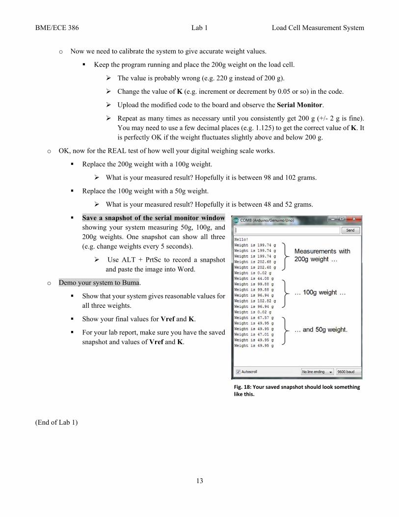
Save a snapshot of the serial monitor window showing your system measuring 50g, 100g, and 200g weights. One snapshot can show all three (e.g. change weights every 5 seconds).
Use ALT + PrtSc to record a snapshot and paste the image into Word.
o Demo your system to Buma.
Show that your system gives reasonable values for all three weights.
Show your final values for Vref and K.
For your lab report, make sure you have the saved snapshot and values of Vref and K.
(End of Lab 1)
Fig. 18: Your saved snapshot should look something like this.