Embed Size (px)
Citation preview
13
2
Understanding Layer 2, 3, and 4 Protocols
hile many of the concepts well known to traditional Layer 2 and Layer 3 net-working still hold true in content switching applications, the area introducesnew and more complex themes that need to be well understood for any success-ful implementation. Within the discussion of content networking, we willreplace terms such as
packets
and
frames
with
sessions
and
transactions
as we moveour attention further up the OSI Seven Layer Model. Before we move intothese new terms, however, let’s look at some standard Layer 2, 3, and 4 network-ing concepts.
The OSI Seven Layer Model—What
Is
a Layer?
Established in 1947, the International Organization for Standardization (ISO)was formed to bring together the standards bodies from countries around theworld. Their definition of the model for Open Systems Interconnection, orOSI, is used to define modes of interconnection between different componentsin a networking system. This means that the physical method of transport canbe designed independently of the protocols and applications running over it. Forexample, TCP/IP can be run over both Ethernet and FDDI networks, andNovell’s IPX and Apple’s AppleTalk protocols can both be run over Token Ringnetworks. These are examples of having independence between the physical net-work type and the upper layer protocols running across them. Consider also, twoTCP/IP-enabled end systems communicating across a multitude of different
W
14
Chapter 2
●
U
NDERSTANDING
L
AYER
2, 3,
AND
4 P
ROTOCOLS
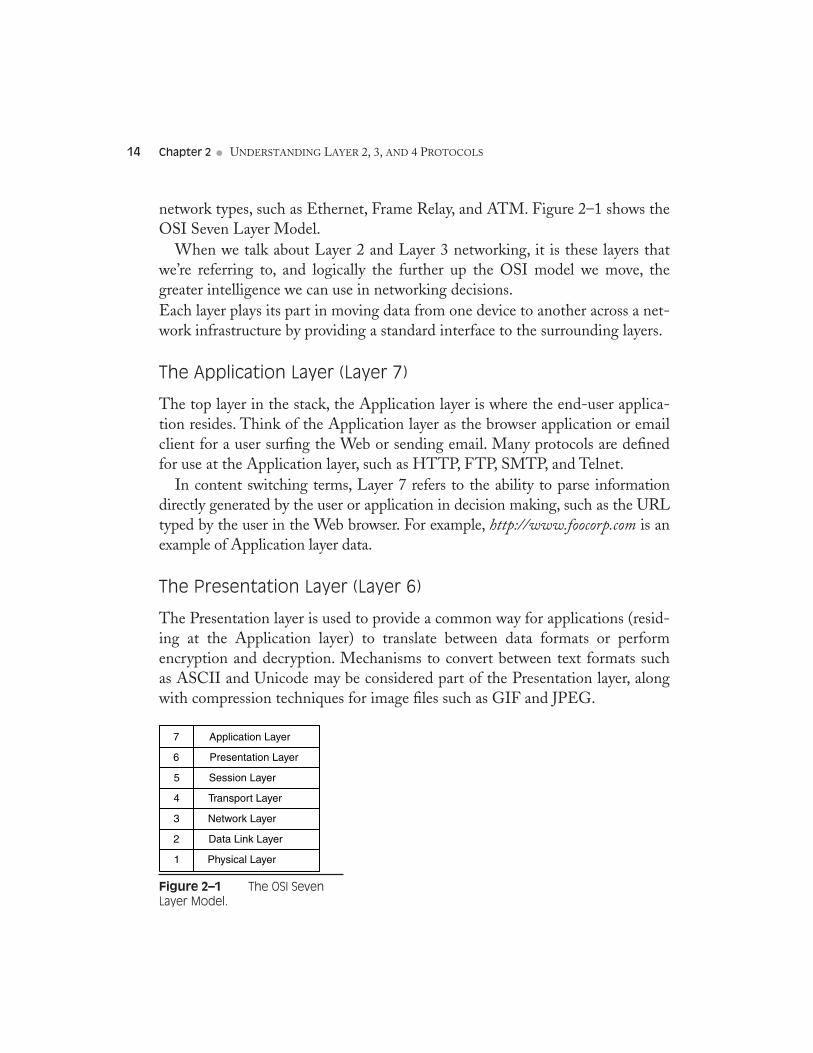
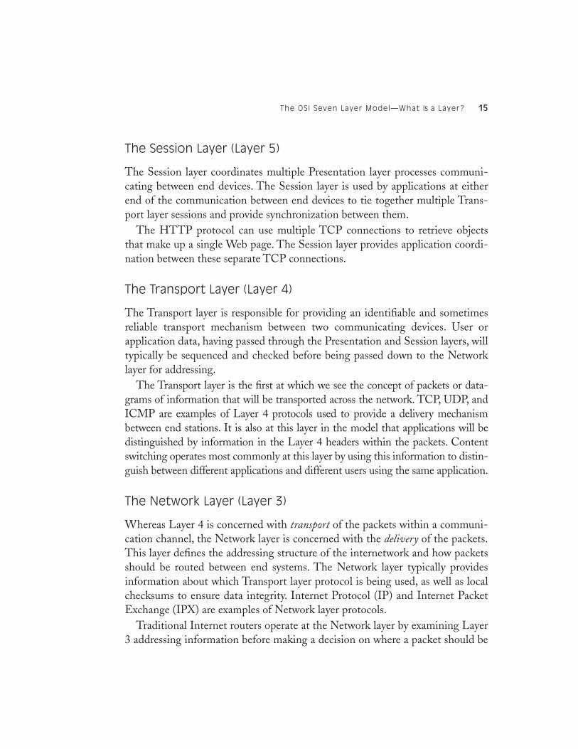
network types, such as Ethernet, Frame Relay, and ATM. Figure 2–1 shows theOSI Seven Layer Model.
When we talk about Layer 2 and Layer 3 networking, it is these layers thatwe’re referring to, and logically the further up the OSI model we move, thegreater intelligence we can use in networking decisions. Each layer plays its part in moving data from one device to another across a net-work infrastructure by providing a standard interface to the surrounding layers.
The Application Layer (Layer 7)
The top layer in the stack, the Application layer is where the end-user applica-tion resides. Think of the Application layer as the browser application or emailclient for a user surfing the Web or sending email. Many protocols are definedfor use at the Application layer, such as HTTP, FTP, SMTP, and Telnet.
In content switching terms, Layer 7 refers to the ability to parse informationdirectly generated by the user or application in decision making, such as the URLtyped by the user in the Web browser. For example,
http://www.foocorp.com
is anexample of Application layer data.
The Presentation Layer (Layer 6)
The Presentation layer is used to provide a common way for applications (resid-ing at the Application layer) to translate between data formats or performencryption and decryption. Mechanisms to convert between text formats suchas ASCII and Unicode may be considered part of the Presentation layer, alongwith compression techniques for image files such as GIF and JPEG.
Figure 2–1
The OSI Seven Layer Model.
7 Application Layer
6 Presentation Layer
5 Session Layer
4 Transport Layer
3 Network Layer
2 Data Link Layer
1 Physical Layer
The OSI Seven Layer Model—What Is a Layer?
15
The Session Layer (Layer 5)
The Session layer coordinates multiple Presentation layer processes communi-cating between end devices. The Session layer is used by applications at eitherend of the communication between end devices to tie together multiple Trans-port layer sessions and provide synchronization between them.
The HTTP protocol can use multiple TCP connections to retrieve objectsthat make up a single Web page. The Session layer provides application coordi-nation between these separate TCP connections.
The Transport Layer (Layer 4)
The Transport layer is responsible for providing an identifiable and sometimesreliable transport mechanism between two communicating devices. User orapplication data, having passed through the Presentation and Session layers, willtypically be sequenced and checked before being passed down to the Networklayer for addressing.
The Transport layer is the first at which we see the concept of packets or data-grams of information that will be transported across the network. TCP, UDP, andICMP are examples of Layer 4 protocols used to provide a delivery mechanismbetween end stations. It is also at this layer in the model that applications will bedistinguished by information in the Layer 4 headers within the packets. Contentswitching operates most commonly at this layer by using this information to distin-guish between different applications and different users using the same application.
The Network Layer (Layer 3)
Whereas Layer 4 is concerned with
transport
of the packets within a communi-cation channel, the Network layer is concerned with the
delivery
of the packets.This layer defines the addressing structure of the internetwork and how packetsshould be routed between end systems. The Network layer typically providesinformation about which Transport layer protocol is being used, as well as localchecksums to ensure data integrity. Internet Protocol (IP) and Internet PacketExchange (IPX) are examples of Network layer protocols.
Traditional Internet routers operate at the Network layer by examining Layer3 addressing information before making a decision on where a packet should be
16
Chapter 2
●
U
NDERSTANDING
L
AYER
2, 3,
AND
4 P
ROTOCOLS
forwarded. Hardware-based Layer 3 switches also use Layer 3 information inforwarding decisions. Layer 3 routers and switches are not concerned whetherthe packets contain HTTP, FTP, or SMTP data, but simply where the packet isflowing to and from.
The Data Link Layer (Layer 2)
The Data Link layer also defines a lower level addressing structure to be usedbetween end systems as well as the lower level framing and checksums beingused to transmit onto the physical medium. Ethernet, Token Ring, and FrameRelay are all examples of Data Link layer or Layer 2 protocols.
Traditional Ethernet switches operate at the Data Link layer and are con-cerned with forwarding packets based on the Layer 2 addressing scheme. Layer2 Ethernet switches are not concerned with whether the packet contains IP,IPX, or AppleTalk, but only with where the MAC address of the recipient endsystem resides.
The Physical Layer (Layer 1)
As with all computer systems, networking is ultimately about making, moving,and storing 1s and 0s. In networking terms, the Physical layer defines how theuser’s browser application data is turned into 1s and 0s to be transmitted ontothe physical medium. The Physical layer defines the physical medium such ascabling and interface specifications. AUI, 10Base-T, and RJ45 are all examplesof Layer 1 specifications.
Putting All the Layers Together
Let’s take an example of a Web user visiting the Web site of Foocorp, Inc.Within the browser application, at the Application layer, the user will type inthe URL, typically something like
http://www.foocorp.com/
. While this is theonly input the
user
will provide the application, there is much more informationgenerated by the browser application itself, including:
• The type of browser being used (e.g., Microsoft Internet Explorer,Netscape)
• The operating system running on the user’s machine
The OSI Seven Layer Model—What Is a Layer?
17
• The version of the HTTP protocol being used by the browser• The language, or languages, supported by the browser (e.g., English,
Japanese, etc.)• Any Presentation layer standards that are supported by the browser, such
as compression types, text formats, and file types
In terms of HTTP-based Web browser traffic, these pieces of informationcan be thought of as the Application, Presentation, and Session layers of theOSI model. They provide not only the raw data input by the user in the applica-tion, but also information needed by the application to ensure successful com-munication with the end system; in this case, a Web server at Foocorp. HTTPinformation for the Web user would look something like:
Hypertext Transfer Protocol
GET / HTTP/1.0\r\nAccept: image/gif, image/x-xbitmap, image/jpeg, image/pjpeg\r\nAccept-Language: en-gb\r\nUser-Agent: Mozilla/4.0 (compatible; MSIE 5.01; Windows NT 5.0)\r\nHost: www.foocorp.com\r\nConnection: Keep-Alive\r\n\r\n
Once this application information has been generated, it can be packaged andpassed on to the next layer for transport. HTTP requires a connection-orientedTransport layer protocol to guarantee the delivery of each packet in the session.Transmission Control Protocol (TCP) is used in HTTP applications to ensurethis successful packet delivery. Other applications will make use of differentTransport layer protocols. TFTP, for example, uses the User Datagram Protocol(UDP) as its Layer 4 transport because it does not require the guaranteed deliv-ery provided by TCP. Routing updates sent between Layer 3 devices can useOSPF, RIP, or BGP as their Layer 4 transport.
At the Transport layer, information about the port numbers, sequence num-bers, and checksums are included to provide reliable transport. The Layer 4headers in our example would look something like:
Transmission Control Protocol Source port: 3347 (3347) Destination port: http (80) Sequence number: 52818332 Next sequence number: 52818709 Acknowledgement number: 3364222344
18
Chapter 2
●
U
NDERSTANDING
L
AYER
2, 3,
AND
4 P
ROTOCOLS
Header length: 20 bytes
Flags: 0x0018 (PSH, ACK)
0... .... = Congestion Window Reduced (CWR): Not set
.0.. .... = ECN-Echo: Not set
..0. .... = Urgent: Not set
...1 .... = Acknowledgment: Set
.... 1... = Push: Set
.... .0.. = Reset: Not set
.... ..0. = Syn: Not set
.... ...0 = Fin: Not set
Window size: 17520
Checksum: 0xb043 (correct)
Once the Transport layer information has been added to the head of thepacket, it is passed to the Network layer for the Layer 3 headers to be appended.The Network layer will include information on the IP addresses of both the cli-ent and the end system, and a reference to which Transport layer protocol hasbeen used. The Network layer information is used to ensure the correct deliverypath from the client to the end system and the ability for the receiver to identifywhich Transport layer process the frames should be forwarded to once theyarrive. For the Web user example, the Network layer information would look asfollows:
Internet Protocol
Version: 4
Header length: 20 bytes
Time to live: 128
Protocol: TCP
Header checksum: 0x2df9 (correct)
Source: 192.168.254.201 (192.168.254.201)
Destination: 216.239.51.101 (216.239.51.101)
For transmission across the local, physical network, the frame is thenpassed to the Data Link layer for the addition of the local physical addresses.In terms of Ethernet, this would be the Ethernet Media Access Control(MAC) address of the user machine and the MAC address of the defaultgateway router on the Ethernet network. The Layer 2 protocol, such asEthernet, will also include a reference to which Layer 3 protocol has beenused and a checksum to ensure data integrity. For our example, the Layer 2information might look something like:
Ethernet II
Destination: 00:20:6f:14:58:2f (00:20:6f:14:58:2f)
Switching at Different Layers
19
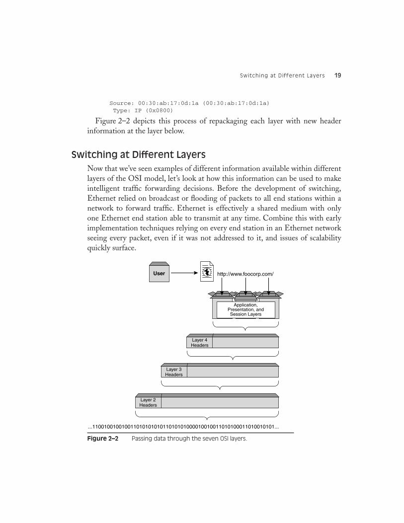
Source: 00:30:ab:17:0d:1a (00:30:ab:17:0d:1a) Type: IP (0x0800)
Figure 2–2 depicts this process of repackaging each layer with new headerinformation at the layer below.
Switching at Different Layers
Now that we’ve seen examples of different information available within differentlayers of the OSI model, let’s look at how this information can be used to makeintelligent traffic forwarding decisions. Before the development of switching,Ethernet relied on broadcast or flooding of packets to all end stations within anetwork to forward traffic. Ethernet is effectively a shared medium with onlyone Ethernet end station able to transmit at any time. Combine this with earlyimplementation techniques relying on every end station in an Ethernet networkseeing every packet, even if it was not addressed to it, and issues of scalabilityquickly surface.
Figure 2–2
Passing data through the seven OSI layers.
http://www.foocorp.com/
...11001001001001101010101011010101000010010011010100011010010101...
User
Layer 4Headers
Application,Presentation, andSession Layers
Layer 3Headers
Layer 2Headers
20
Chapter 2
●
U
NDERSTANDING
L
AYER
2, 3,
AND
4 P
ROTOCOLS
Layer 2 Switching
The first implementation of Ethernet or Layer 2 switching uses information inthe Ethernet headers to make traffic forwarding decisions. Intelligent switcheslearn which ports have which end stations attached by recording the EthernetMAC addresses of packets ingressing the switch. Using this information alongwith the ability to parse the Layer 2 headers of all packets means that a Layer 2switch need only forward frames out of ports where it knows the end station tobe. For end station addresses that have not yet been learned, frames withunknown destination MAC addresses are flooded out of every port in the switchto force the recipient to reply. This will allow the switch to learn the relevantMAC address, as it will be the
source
address on the reply frame.Layer 2 switching is implemented along side Layer 3 routing for local area
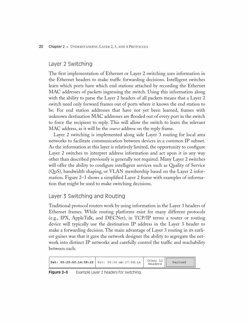
networks to facilitate communication between devices in a common IP subnet.As the information at this layer is relatively limited, the opportunity to configureLayer 2 switches to interpret address information and act upon it in any wayother than described previously is generally not required. Many Layer 2 switcheswill offer the ability to configure intelligent services such as Quality of Service(QoS), bandwidth shaping, or VLAN membership based on the Layer 2 infor-mation. Figure 2–3 shows a simplified Layer 2 frame with examples of informa-tion that might be used to make switching decisions.
Layer 3 Switching and Routing
Traditional protocol routers work by using information in the Layer 3 headers ofEthernet frames. While routing platforms exist for many different protocols(e.g., IPX, AppleTalk, and DECNet), in TCP/IP terms a router or routingdevice will typically use the destination IP address in the Layer 3 header tomake a forwarding decision. The main advantage of Layer 3 routing in its earli-est guises was that it gave the network designer the ability to segregate the net-work into distinct IP networks and carefully control the traffic and reachabilitybetween each.
Figure 2–3
Example Layer 2 headers for switching.
Dst: 00:20:6f:14:58:2f Src: 00:30:ab:17:0d:1a PayloadOther L2Headers
Understanding Layer 4 Protocols
21
Many of the early implementers and pioneers of Layer 3 routing devices usedsoftware-based devices as platforms that, while offering a flexible platform fordevelopment of the technology, often provided limitations in terms of perfor-mance. As Layer 2 switching became more commonplace and the price per portof Ethernet switching systems dropped, manufacturers looked to combine theperformance of ASIC-based Layer 2 switching with the functionality and flexi-bility of Layer 3 routing. Step forward the Layer 3 switch. Layer 3 switcheswork by examining the destination IP address and making a forwarding decisionbased on the routing configuration implemented. The destination subnet mightbe learned via a connected interface, a static route, or a dynamic routing protocolsuch as RIP, OSPF, or BGP. In all instances, once the Layer 3 switch has exam-ined the frame and compared the destination IP address against the informationin its routing database, the destination MAC address is changed and the frameis forwarded through the relevant egress port. For IP frames traversing a Layer 3device, such as a router or Layer 3 switch, the TTL field in the IP header is alsodecremented to indicate to end stations and intermediaries that a routing hophas occurred.
It is once we reach the Layer 3 switching environment that configuration fordevices become inherently more complex. The administrator must configure thecorrect routing information to enable basic traffic flow along with the interfaceIP addresses in each of the subnets to which the Layer 3 switch is attached.
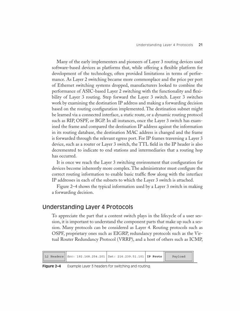
Figure 2–4 shows the typical information used by a Layer 3 switch in makinga forwarding decision.
Understanding Layer 4 Protocols
To appreciate the part that a content switch plays in the lifecycle of a user ses-sion, it is important to understand the component parts that make up such a ses-sion. Many protocols can be considered as Layer 4. Routing protocols such asOSPF, proprietary ones such as EIGRP, redundancy protocols such as the Vir-tual Router Redundancy Protocol (VRRP), and a host of others such as ICMP,
Figure 2–4
Example Layer 3 headers for switching and routing.
Src: 192.168.254.201 Dst: 216.239.51.101 PayloadIP ProtoL2 Headers
22
Chapter 2
●
U
NDERSTANDING
L
AYER
2, 3,
AND
4 P
ROTOCOLS
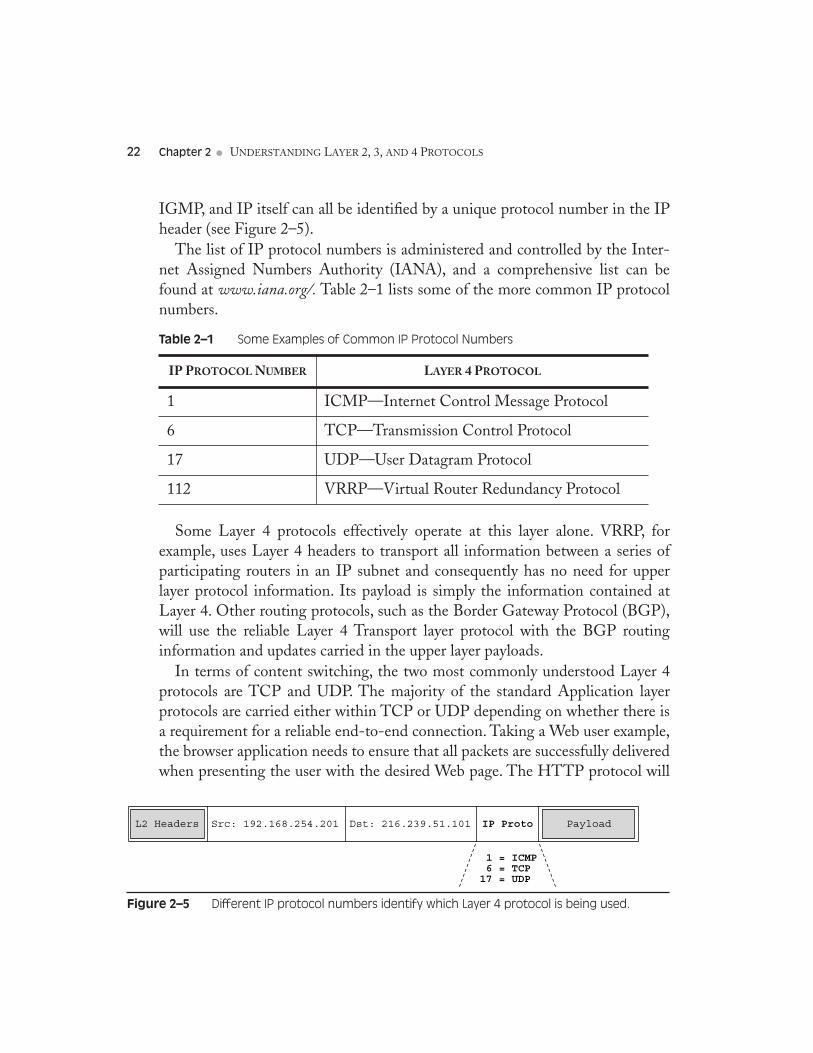
IGMP, and IP itself can all be identified by a unique protocol number in the IPheader (see Figure 2–5).
The list of IP protocol numbers is administered and controlled by the Inter-net Assigned Numbers Authority (IANA), and a comprehensive list can befound at
www.iana.org/.
Table 2–1 lists some of the more common IP protocolnumbers.
Some Layer 4 protocols effectively operate at this layer alone. VRRP, forexample, uses Layer 4 headers to transport all information between a series ofparticipating routers in an IP subnet and consequently has no need for upperlayer protocol information. Its payload is simply the information contained atLayer 4. Other routing protocols, such as the Border Gateway Protocol (BGP),will use the reliable Layer 4 Transport layer protocol with the BGP routinginformation and updates carried in the upper layer payloads.
In terms of content switching, the two most commonly understood Layer 4protocols are TCP and UDP. The majority of the standard Application layerprotocols are carried either within TCP or UDP depending on whether there isa requirement for a reliable end-to-end connection. Taking a Web user example,the browser application needs to ensure that all packets are successfully deliveredwhen presenting the user with the desired Web page. The HTTP protocol will
Table 2–1
Some Examples of Common IP Protocol Numbers
IP P
ROTOCOL
N
UMBER
L
AYER
4 P
ROTOCOL
1 ICMP—Internet Control Message Protocol
6 TCP—Transmission Control Protocol
17 UDP—User Datagram Protocol
112 VRRP—Virtual Router Redundancy Protocol
Figure 2–5
Different IP protocol numbers identify which Layer 4 protocol is being used.
Src: 192.168.254.201 Dst: 216.239.51.101 PayloadIP Proto
1 = ICMP 6 = TCP17 = UDP
L2 Headers
Transport Control Protocol (TCP)
23
therefore rely on TCP as its Transport layer protocol, to guarantee delivery,which in turn will use IP as its delivery mechanism.
Transport Control Protocol (TCP)
As the Layer 3 IP protocol is principally a connectionless and best-efforts deliverymechanism, there is a requirement for many applications to ensure the correctlysequenced delivery of
all
packets within a conversation. Consequently, many appli-cations will use Transport Control Protocol (TCP) at Layer 4 to guarantee success-ful delivery. TCP has several characteristics built in to ensure this delivery:
•
Checksum
:
The TCP header contains a 16-bit data checksum that iscomputed from all other data elements in the TCP header. The receivingend station uses this checksum to ensure that the packet arrived withoutcorruption.
•
Sequence and acknowledgment numbers
:
Each octet of data sent andreceived by end stations has an associated sequence number associatedwith it. These sequence numbers are cumulative, whereby a certainsequence number inside the TCP header will be used to indicate that alldata up to and including
X
should have been received. Sequence andacknowledgment numbering is used to bring the concept of order topacket delivery over IP.
•
Windowing
: The TCP windowing technique allows two communicat-ing end stations to build on the sequencing and acknowledgments aboveby removing the need for each sequence of data to be individuallyacknowledged. In LANs where packet loss is usually minimal, it is farmore efficient to allow the sender to transmit several frames of databefore an acknowledgment is sent.
Along with these mechanisms, TCP must also be able to uniquely identifyeach conversation within an internetwork. We’ve already seen the idea of a TCPport number that is used, among other things, to identify the application processto the high OSI layers during the conversation. Within a TCP conversation,there are in fact two port numbers used: one to identify the sender’s listeningport and the other to identify the receiver’s listening port. Depending on thedirection of each individual frame in the conversation, these ports become eitherthe source port or the destination port within the Layer 4 headers.
24
Chapter 2
●
U
NDERSTANDING
L
AYER
2, 3,
AND
4 P
ROTOCOLS
This combination of source and destination ports, along with the Layer 3 IPaddressing, gives TCP the ability to uniquely identify each conversation or ses-sion within an internetwork, even in the case of the Internet itself.
The Lifecycle of a TCP Session
Let’s put these concepts of addresses, ports, and sequencing numbers togetherand look at how a conversation between two end stations is initiated, sustained,and terminated. Throughout the following example, we will assume that the cli-ent is a PC (10.10.10.10) initiating a connection to a Web server (20.20.20.20).
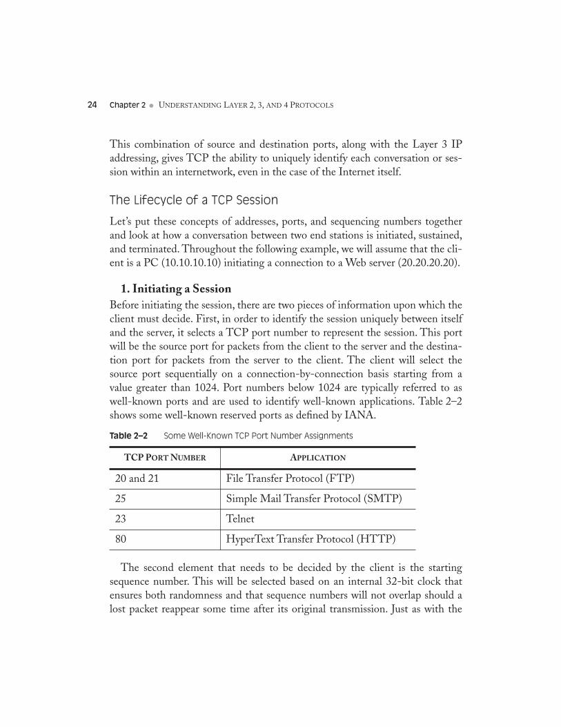
1. Initiating a SessionBefore initiating the session, there are two pieces of information upon which theclient must decide. First, in order to identify the session uniquely between itselfand the server, it selects a TCP port number to represent the session. This portwill be the source port for packets from the client to the server and the destina-tion port for packets from the server to the client. The client will select thesource port sequentially on a connection-by-connection basis starting from avalue greater than 1024. Port numbers below 1024 are typically referred to aswell-known ports and are used to identify well-known applications. Table 2–2shows some well-known reserved ports as defined by IANA.
The second element that needs to be decided by the client is the startingsequence number. This will be selected based on an internal 32-bit clock thatensures both randomness and that sequence numbers will not overlap should alost packet reappear some time after its original transmission. Just as with the
Table 2–2 Some Well-Known TCP Port Number Assignments
TCP PORT NUMBER APPLICATION
20 and 21 File Transfer Protocol (FTP)
25 Simple Mail Transfer Protocol (SMTP)
23 Telnet
80 HyperText Transfer Protocol (HTTP)
Transport Control Protocol (TCP) 25
TCP ports used by both the client and server, each side also uses its ownsequence numbering to identify where within the session each frame fits.
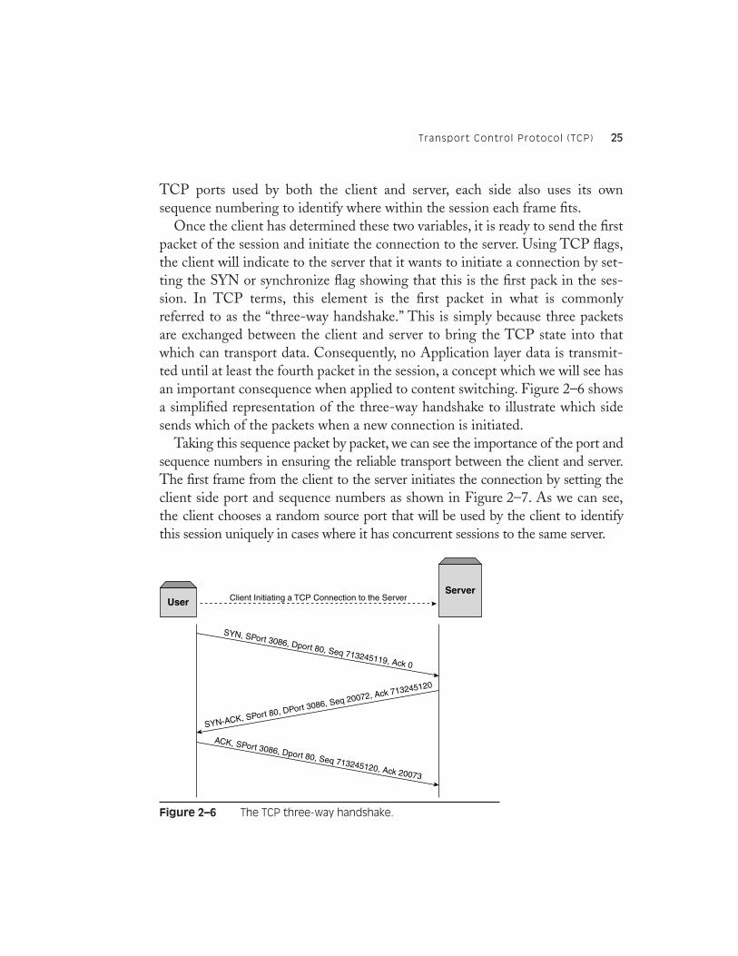
Once the client has determined these two variables, it is ready to send the firstpacket of the session and initiate the connection to the server. Using TCP flags,the client will indicate to the server that it wants to initiate a connection by set-ting the SYN or synchronize flag showing that this is the first pack in the ses-sion. In TCP terms, this element is the first packet in what is commonlyreferred to as the “three-way handshake.” This is simply because three packetsare exchanged between the client and server to bring the TCP state into thatwhich can transport data. Consequently, no Application layer data is transmit-ted until at least the fourth packet in the session, a concept which we will see hasan important consequence when applied to content switching. Figure 2–6 showsa simplified representation of the three-way handshake to illustrate which sidesends which of the packets when a new connection is initiated.
Taking this sequence packet by packet, we can see the importance of the port andsequence numbers in ensuring the reliable transport between the client and server.The first frame from the client to the server initiates the connection by setting theclient side port and sequence numbers as shown in Figure 2–7. As we can see,the client chooses a random source port that will be used by the client to identifythis session uniquely in cases where it has concurrent sessions to the same server.
Figure 2–6 The TCP three-way handshake.
Client Initiating a TCP Connection to the ServerUserServer
SYN, SPort 3086, Dport 80, Seq 713245119, Ack 0
SYN-ACK, SPort 80, DPort 3086, Seq 20072, Ack 713245120
ACK, SPort 3086, Dport 80, Seq 713245120, Ack 20073
26 Chapter 2 ● UNDERSTANDING LAYER 2, 3, AND 4 PROTOCOLS
When the server replies, both the SYN and ACK flags are set in the TCPheaders to indicate that the server acknowledges the client’s connection request.To ensure that each packet can be accounted for, the server will set an acknowl-edgment number that is equal to the last byte received from the client, relative tothe starting sequence number, plus one. In our example, the client started with asequence number of 713245119 and transmitted no user data, meaning that theserver will use an acknowledgment of 713245120.
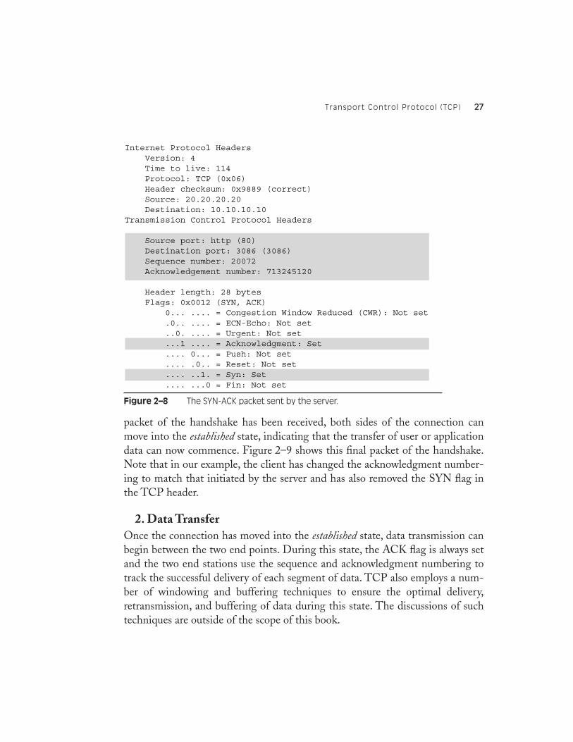
It is also important to notice the change in source and destination portsdepending on which way a particular packet is directed. In our example, the cli-ent sends on port 80 and listens on port 3086, whereas the server sends on port3086 and listens on port 80. Figure 2–8 shows the return packet from the serverto the client.
The final packet exchanged during this handshake period is an acknowledg-ment from the client to the server. This allows the client to correctly acknowl-edge the sequence numbering used by the server in the previous packet andremove the SYN flag being used to show the start of the session. Once this final
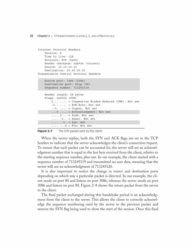
Figure 2–7 The SYN packet sent by the client.
Internet Protocol Headers Version: 4 Time to live: 128 Protocol: TCP (0x06) Header checksum: 0xb926 (correct) Source: 10.10.10.10 Destination: 20.20.20.20Transmission Control Protocol Headers
Source port: 3086 (3086) Destination port: http (80) Sequence number: 713245119
Header length: 28 bytes Flags: 0x0002 (SYN) 0... .... = Congestion Window Reduced (CWR): Not set .0.. .... = ECN-Echo: Not set ..0. .... = Urgent: Not set ...0 .... = Acknowledgment: Not set .... 0... = Push: Not set .... .0.. = Reset: Not set .... ..1. = Syn: Set .... ...0 = Fin: Not set
Transport Control Protocol (TCP) 27
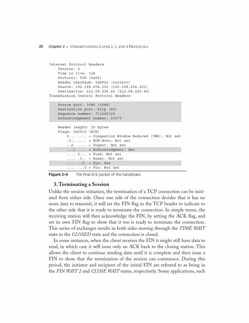
packet of the handshake has been received, both sides of the connection canmove into the established state, indicating that the transfer of user or applicationdata can now commence. Figure 2–9 shows this final packet of the handshake.Note that in our example, the client has changed the acknowledgment number-ing to match that initiated by the server and has also removed the SYN flag inthe TCP header.
2. Data TransferOnce the connection has moved into the established state, data transmission canbegin between the two end points. During this state, the ACK flag is always setand the two end stations use the sequence and acknowledgment numbering totrack the successful delivery of each segment of data. TCP also employs a num-ber of windowing and buffering techniques to ensure the optimal delivery,retransmission, and buffering of data during this state. The discussions of suchtechniques are outside of the scope of this book.
Figure 2–8 The SYN-ACK packet sent by the server.
Internet Protocol Headers Version: 4 Time to live: 114 Protocol: TCP (0x06) Header checksum: 0x9889 (correct) Source: 20.20.20.20 Destination: 10.10.10.10Transmission Control Protocol Headers
Source port: http (80) Destination port: 3086 (3086) Sequence number: 20072 Acknowledgement number: 713245120
Header length: 28 bytes Flags: 0x0012 (SYN, ACK) 0... .... = Congestion Window Reduced (CWR): Not set .0.. .... = ECN-Echo: Not set ..0. .... = Urgent: Not set ...1 .... = Acknowledgment: Set .... 0... = Push: Not set .... .0.. = Reset: Not set .... ..1. = Syn: Set .... ...0 = Fin: Not set
28 Chapter 2 ● UNDERSTANDING LAYER 2, 3, AND 4 PROTOCOLS
3. Terminating a SessionUnlike the session initiation, the termination of a TCP connection can be initi-ated from either side. Once one side of the connection decides that it has nomore data to transmit, it will set the FIN flag in the TCP header to indicate tothe other side that it is ready to terminate the connection. In simple terms, thereceiving station will then acknowledge the FIN, by setting the ACK flag, andset its own FIN flag to show that it too is ready to terminate the connection.This series of exchanges results in both sides moving through the TIME WAITstate to the CLOSED state and the connection is closed.
In some instances, when the client receives the FIN it might still have data tosend, in which case it will issue only an ACK back to the closing station. Thisallows the client to continue sending data until it is complete and then issue aFIN to show that the termination of the session can commence. During thisperiod, the initiator and recipient of the initial FIN are referred to as being inthe FIN WAIT 2 and CLOSE WAIT states, respectively. Some applications, such
Figure 2–9 The final ACK packet of the handshake.
Internet Protocol Headers Version: 4 Time to live: 128 Protocol: TCP (0x06) Header checksum: 0xb92c (correct) Source: 192.168.254.201 (192.168.254.201) Destination: 212.58.226.40 (212.58.226.40)Transmission Control Protocol Headers
Source port: 3086 (3086) Destination port: http (80) Sequence number: 713245120 Acknowledgement number: 20073
Header length: 20 bytes Flags: 0x0010 (ACK) 0... .... = Congestion Window Reduced (CWR): Not set .0.. .... = ECN-Echo: Not set ..0. .... = Urgent: Not set ...1 .... = Acknowledgment: Set .... 0... = Push: Not set .... .0.. = Reset: Not set .... ..0. = Syn: Set .... ...0 = Fin: Not set
User Datagram Protocol (UDP) 29
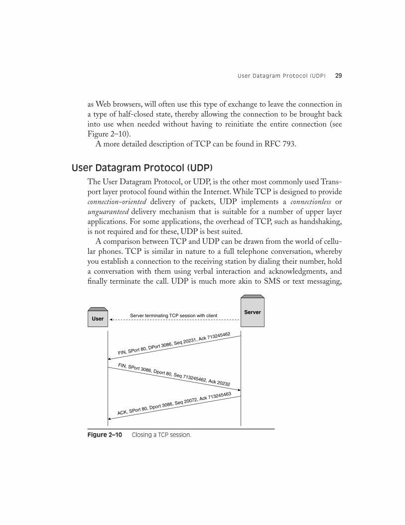
as Web browsers, will often use this type of exchange to leave the connection ina type of half-closed state, thereby allowing the connection to be brought backinto use when needed without having to reinitiate the entire connection (seeFigure 2–10).
A more detailed description of TCP can be found in RFC 793.
User Datagram Protocol (UDP)
The User Datagram Protocol, or UDP, is the other most commonly used Trans-port layer protocol found within the Internet. While TCP is designed to provideconnection-oriented delivery of packets, UDP implements a connectionless orunguaranteed delivery mechanism that is suitable for a number of upper layerapplications. For some applications, the overhead of TCP, such as handshaking,is not required and for these, UDP is best suited.
A comparison between TCP and UDP can be drawn from the world of cellu-lar phones. TCP is similar in nature to a full telephone conversation, wherebyyou establish a connection to the receiving station by dialing their number, holda conversation with them using verbal interaction and acknowledgments, andfinally terminate the call. UDP is much more akin to SMS or text messaging,
Figure 2–10 Closing a TCP session.
Server terminating TCP session with clientUser
Server
FIN, SPort 80, DPort 3086, Seq 20231, Ack 713245462
ACK, SPort 80, Dport 3086, Seq 20072, Ack 713245463
FIN, SPort 3086, Dport 80, Seq 713245462, Ack 20232
30 Chapter 2 ● UNDERSTANDING LAYER 2, 3, AND 4 PROTOCOLS
whereby you write a message and send it without receiving any acknowledgmentof its delivery from anything other than a local call access point.
UDP does share some common characteristics with TCP, as it does imple-ment source and destination ports, to identify application sockets, and achecksum to verify the correct delivery of the layer 4 datagram.
A Simple UDP Data Flow
Let’s consider our two example machines again, but this time interacting usingUDP rather than TCP. The Domain Name System, or DNS, is one of the mostcommonly implemented UDP-based applications—our example will consider aclient (10.10.10.10) requesting a name resolution from a DNS server(20.20.20.20).
It is important to note that UDP traffic can be both bidirectional, such as therequest-response nature of DNS queries, and unidirectional, such as alerts raisedthrough the Simple Network Management Protocol (SNMP). In bothinstances, the nature of the application determines whether a response isrequired; UDP simply provides a datagram format for the data between the twoend points.
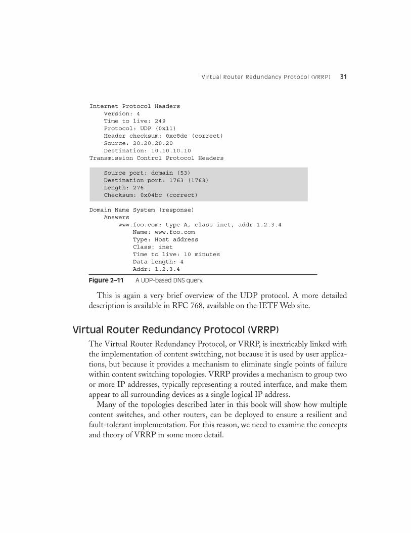
The RequestThe first thing you will notice in Figure 2–11 is that the structure of the UDPheader is far simpler than that used by TCP. There are only four fields usedwithin the UDP header, to indicate the source and destination ports, the headerlength, and the checksum. It is clear from this that many of the techniques usedby TCP are simply not present in UDP, such as sequencing, handshaking, andflow control.
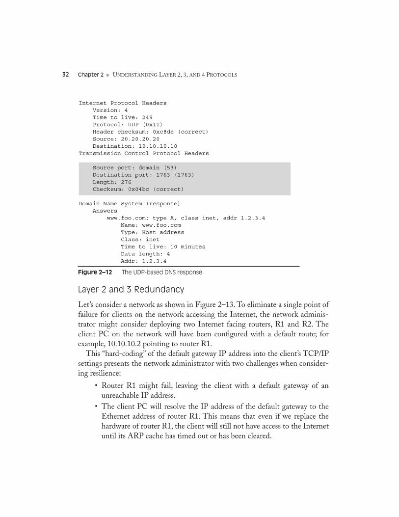
The Response As DNS is a bidirectional, request-response application, the frame shown inFigure 2–11 will yield an answer from the DNS server, also carried usingUDP. Figure 2–12 shows the response. Note that the source and destinationports are reversed as with TCP, as the client sending the request will be listen-ing and expecting an answer on port 1763.
Virtual Router Redundancy Protocol (VRRP) 31
This is again a very brief overview of the UDP protocol. A more detaileddescription is available in RFC 768, available on the IETF Web site.
Virtual Router Redundancy Protocol (VRRP)
The Virtual Router Redundancy Protocol, or VRRP, is inextricably linked withthe implementation of content switching, not because it is used by user applica-tions, but because it provides a mechanism to eliminate single points of failurewithin content switching topologies. VRRP provides a mechanism to group twoor more IP addresses, typically representing a routed interface, and make themappear to all surrounding devices as a single logical IP address.
Many of the topologies described later in this book will show how multiplecontent switches, and other routers, can be deployed to ensure a resilient andfault-tolerant implementation. For this reason, we need to examine the conceptsand theory of VRRP in some more detail.
Figure 2–11 A UDP-based DNS query.
Internet Protocol Headers Version: 4 Time to live: 249 Protocol: UDP (0x11) Header checksum: 0xc8de (correct) Source: 20.20.20.20 Destination: 10.10.10.10Transmission Control Protocol Headers
Source port: domain (53) Destination port: 1763 (1763) Length: 276 Checksum: 0x04bc (correct)
Domain Name System (response) Answers www.foo.com: type A, class inet, addr 1.2.3.4 Name: www.foo.com Type: Host address Class: inet Time to live: 10 minutes Data length: 4 Addr: 1.2.3.4
32 Chapter 2 ● UNDERSTANDING LAYER 2, 3, AND 4 PROTOCOLS
Layer 2 and 3 Redundancy
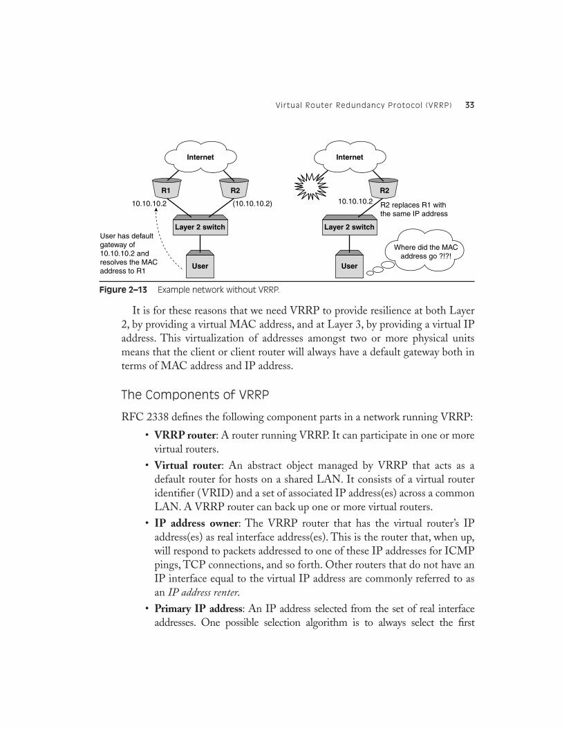
Let’s consider a network as shown in Figure 2–13. To eliminate a single point offailure for clients on the network accessing the Internet, the network adminis-trator might consider deploying two Internet facing routers, R1 and R2. Theclient PC on the network will have been configured with a default route; forexample, 10.10.10.2 pointing to router R1.
This “hard-coding” of the default gateway IP address into the client’s TCP/IPsettings presents the network administrator with two challenges when consider-ing resilience:
• Router R1 might fail, leaving the client with a default gateway of anunreachable IP address.
• The client PC will resolve the IP address of the default gateway to theEthernet address of router R1. This means that even if we replace thehardware of router R1, the client will still not have access to the Internetuntil its ARP cache has timed out or has been cleared.
Figure 2–12 The UDP-based DNS response.
Internet Protocol Headers Version: 4 Time to live: 249 Protocol: UDP (0x11) Header checksum: 0xc8de (correct) Source: 20.20.20.20 Destination: 10.10.10.10Transmission Control Protocol Headers
Source port: domain (53) Destination port: 1763 (1763) Length: 276 Checksum: 0x04bc (correct)
Domain Name System (response) Answers www.foo.com: type A, class inet, addr 1.2.3.4 Name: www.foo.com Type: Host address Class: inet Time to live: 10 minutes Data length: 4 Addr: 1.2.3.4
Virtual Router Redundancy Protocol (VRRP) 33
It is for these reasons that we need VRRP to provide resilience at both Layer2, by providing a virtual MAC address, and at Layer 3, by providing a virtual IPaddress. This virtualization of addresses amongst two or more physical unitsmeans that the client or client router will always have a default gateway both interms of MAC address and IP address.
The Components of VRRP
RFC 2338 defines the following component parts in a network running VRRP:
• VRRP router: A router running VRRP. It can participate in one or morevirtual routers.
• Virtual router: An abstract object managed by VRRP that acts as adefault router for hosts on a shared LAN. It consists of a virtual routeridentifier (VRID) and a set of associated IP address(es) across a commonLAN. A VRRP router can back up one or more virtual routers.
• IP address owner: The VRRP router that has the virtual router’s IPaddress(es) as real interface address(es). This is the router that, when up,will respond to packets addressed to one of these IP addresses for ICMPpings, TCP connections, and so forth. Other routers that do not have anIP interface equal to the virtual IP address are commonly referred to asan IP address renter.
• Primary IP address: An IP address selected from the set of real interfaceaddresses. One possible selection algorithm is to always select the first
Figure 2–13 Example network without VRRP.
User
Layer 2 switch
10.10.10.2 (10.10.10.2)
User has defaultgateway of10.10.10.2 andresolves the MACaddress to R1
R2 replaces R1 withthe same IP address
Where did the MACaddress go ?!?!
R1 R2
Internet
User
Layer 2 switch
10.10.10.2
R2
Internet
34 Chapter 2 ● UNDERSTANDING LAYER 2, 3, AND 4 PROTOCOLS
address. VRRP advertisements are always sent using the primary IP addressas the source of the IP packet.
• Virtual router master: The VRRP router that is assuming the responsi-bility of forwarding packets sent to the IP address(es) associated with thevirtual router, and answering ARP requests for these IP addresses. Notethat if the IP address owner is available, it will always become the master.
• Virtual router backup: The set of VRRP routers available to assume for-warding responsibility for a virtual router should the current master fail.
• VRID: Configured item in the range 1–255 (decimal). There is no default.
• Priority: Priority value to be used by this VRRP router in master elec-tion for this virtual router. The value of 255 (decimal) is reserved for therouter that owns the IP addresses associated with the virtual router. Thevalue of 0 (zero) is reserved for the master router to indicate that it isreleasing responsibility for the virtual router. The range 1–254 (decimal)is available for VRRP routers backing up the virtual router. The defaultvalue is 100 (decimal).
VRRP Addressing
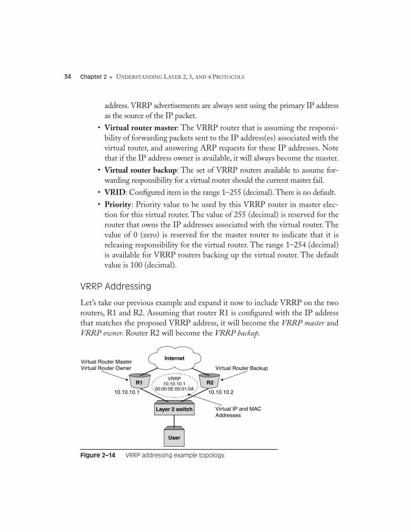
Let’s take our previous example and expand it now to include VRRP on the tworouters, R1 and R2. Assuming that router R1 is configured with the IP addressthat matches the proposed VRRP address, it will become the VRRP master andVRRP owner. Router R2 will become the VRRP backup.
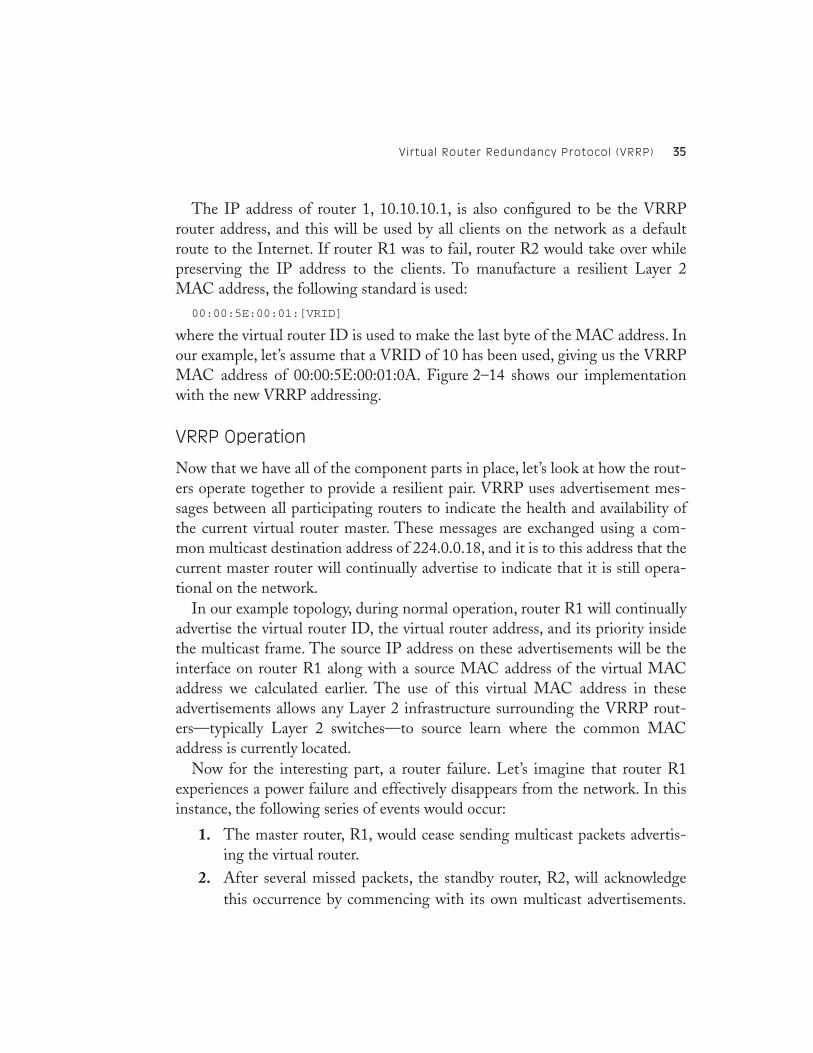
Figure 2–14 VRRP addressing example topology.
User
Layer 2 switch
10.10.10.1 10.10.10.2
R1 R2
Internet
VRRP10.10.10.1
00:00:5E:00:01:0A
Virtual Router MasterVirtual Router Owner Virtual Router Backup
Virtual IP and MACAddresses
Virtual Router Redundancy Protocol (VRRP) 35
The IP address of router 1, 10.10.10.1, is also configured to be the VRRProuter address, and this will be used by all clients on the network as a defaultroute to the Internet. If router R1 was to fail, router R2 would take over whilepreserving the IP address to the clients. To manufacture a resilient Layer 2MAC address, the following standard is used:
00:00:5E:00:01:[VRID]
where the virtual router ID is used to make the last byte of the MAC address. Inour example, let’s assume that a VRID of 10 has been used, giving us the VRRPMAC address of 00:00:5E:00:01:0A. Figure 2–14 shows our implementationwith the new VRRP addressing.
VRRP Operation
Now that we have all of the component parts in place, let’s look at how the rout-ers operate together to provide a resilient pair. VRRP uses advertisement mes-sages between all participating routers to indicate the health and availability ofthe current virtual router master. These messages are exchanged using a com-mon multicast destination address of 224.0.0.18, and it is to this address that thecurrent master router will continually advertise to indicate that it is still opera-tional on the network.
In our example topology, during normal operation, router R1 will continuallyadvertise the virtual router ID, the virtual router address, and its priority insidethe multicast frame. The source IP address on these advertisements will be theinterface on router R1 along with a source MAC address of the virtual MACaddress we calculated earlier. The use of this virtual MAC address in theseadvertisements allows any Layer 2 infrastructure surrounding the VRRP rout-ers—typically Layer 2 switches—to source learn where the common MACaddress is currently located.
Now for the interesting part, a router failure. Let’s imagine that router R1experiences a power failure and effectively disappears from the network. In thisinstance, the following series of events would occur:
1. The master router, R1, would cease sending multicast packets advertis-ing the virtual router.
2. After several missed packets, the standby router, R2, will acknowledgethis occurrence by commencing with its own multicast advertisements.
36 Chapter 2 ● UNDERSTANDING LAYER 2, 3, AND 4 PROTOCOLS
When it does, it will use a source MAC address of the VRRP virtualMAC address, thus informing the attached Layer 2 switch that the MACaddress has moved ports.
3. Since the virtual IP address and associated virtual MAC address havenow survived the failure of router R1, the client will notice only minimaldisruption during the re-election. This period is dependent on the con-figurable parameters associated with the advertisement intervals, butshould typically be no more than 2 to 3 seconds.
VRRP, or variations on it, is commonly implemented in many contentswitching platforms, and as such it forms an important part of any implementa-tion. More information about VRRP can be found in RFC 2338.
Summary
Many books have been written on the TCP/IP protocol stack and the higherlayer applications such as HTTP and FTP that it supports. While it is outsidethe scope of this book to cover all the details and caveats, this chapter providedsufficient overview of the workings most relevant to content switching. Under-standing the concept of a user session—being the total user experience of inter-acting over a period of time with a resource—and how that maps down the OSIseven-layer model and into the frames, packets, and TCP sessions below is keyto understanding and successfully deploying content switching. In Chapter 3,Understanding Application Layer Protocols, we’ll look at some of the Applicationlayer protocols common to content switching.