Embed Size (px)
Citation preview
DefenScientifDRDC-R
August 2
On scorresyste
Ioannis PoDRDC – V
ce Resefic Report RDDC-2019
2019
pectraectionsems
olyzois, PhD, EI Valcartier Res
earch an
9-R147
CA
al waves appli
search Centre
nd Deve
CAN U
AN UNCLAS
e analyied to e
e
lopment
UNCLASSIFIE
SIFIED
ysis wielastic
t Canad
ED
ith disc Hopk
a
tortionkinson
n bar

CAN UNCLASSIFIED
Template in use: EO Publishing App for SR-RD-EC Eng 2018-12-19_v1 (new disclaimer).dotm © Her Majesty the Queen in Right of Canada (Department of National Defence), 2019
© Sa Majesté la Reine en droit du Canada (Ministère de la Défense nationale), 2019
CAN UNCLASSIFIED
IMPORTANT INFORMATIVE STATEMENTS
This document was reviewed for Controlled Goods by Defence Research and Development Canada (DRDC) using the Schedule to the Defence Production Act.
Disclaimer: This publication was prepared by Defence Research and Development Canada an agency of the Department of National Defence. The information contained in this publication has been derived and determined through best practice and adherence to the highest standards of responsible conduct of scientific research. This information is intended for the use of the Department of National Defence, the Canadian Armed Forces (“Canada”) and Public Safety partners and, as permitted, may be shared with academia, industry, Canada’s allies, and the public (“Third Parties”). Any use by, or any reliance on or decisions made based on this publication by Third Parties, are done at their own risk and responsibility. Canada does not assume any liability for any damages or losses which may arise from any use of, or reliance on, the publication.
Endorsement statement: This publication has been peer-reviewed and published by the Editorial Office of Defence Research and Development Canada, an agency of the Department of National Defence of Canada. Inquiries can be sent to: [email protected].

DRDC-RDDC-2019-R147 i
Abstract
The dynamic mechanical properties of materials used in defense applications, under high strain rate and shock loading, are necessary in designing and optimizing their capabilities under such conditions. The Split Hopkinson Pressure Bar (SHPB) technique has been a popular test method for characterizing the properties of materials under dynamic loading at moderate to high strain rates by predicting the propagation of pressure waves in long slender bars. This Scientific Report outlines the procedure for predicting the propagation of pressure waves in an elastic split Hopkinson bar system and correcting for dispersion and radial inertia effects. The procedure is then used to characterize the high strain rate properties of aluminum alloy 6061-T6 under impact and validated against the literature.
Significance to defence and security
This Scientific Report aims to facilitate and improve the efficiency of the characterization of metals and ceramic materials under impact loading using the elastic split Hopkinson bar system at DRDC – Valcartier Research Centre by providing a clear step-by-step procedure for analyzing raw strain gage data and accurately predicting the dynamic response of the test material. The procedure is versatile in that it accommodates all necessary corrections for pressure bar distortion effects using spectral wave analysis for any isotropic elastic bar material with Poisson’s ratio between 0.1 and 0.4, and any bar radius and length.
ii DRDC-RDDC-2019-R147
Résumé
Pour concevoir des matériaux employés aux fins d’applications de défense impliquant des vitesses de déformation élevées et de puissants chocs de chargement, ainsi que pour optimiser les capacités de ces matériaux dans telles conditions, il est important de tenir compte de leurs propriétés mécaniques dynamiques. La technique de la barre de pression Hopkinson (Split Hopkinson Pressure Bar – SHPB) constitue une méthode répandue de caractérisation des propriétés de matériaux soumis à des charges dynamiques impliquant des vitesses de déformation moyennes à élevées, grâce à la prévision de la propagation d’ondes de pression dans de longues barres effilées. Le présent article donne un aperçu d’une procédure suivie pour prévoir la propagation d’ondes de pression dans un système élastique de barre Hopkinson, de même que pour corriger des effets de dispersion et d’inertie radiale. La procédure sert ensuite à caractériser les propriétés de vitesse de déformation élevée de l’alliage d’aluminium 6061-T6 lorsqu’il subit des impacts, ainsi qu’à valider ces propriétés en fonction de ce qui figure dans d’autres articles.
Importance pour la défense et la sécurité
Le présent rapport scientifique vise à faciliter et à améliorer la caractérisation de métaux et de matériaux céramiques soumis à des chocs de chargement d’après le système élastique de barre Hopkinson au RDDC – Centre de recherches Valcartier grâce à l’élaboration d’une procédure systématique claire d’analyse de données extensométriques brutes et de prévision exacte de la réaction dynamique des matériaux éprouvés. La procédure est polyvalente en ce sens qu’elle permet toutes les corrections nécessaires en ce qui concerne les effets de déformation de barre de pression, à l’aide d’une analyse d’onde spectrale ciblant toute barre élastique isotrope présentant un coefficient de Poisson de 0,1 à 0,4, ainsi que tout rayon et toute longueur de barre.

DRDC-RDDC-2019-R147 iii
Table of contents
Abstract . . . . . . . . . . . . . . . . . . . . . . . . . . . . . . . . . . . i
Significance to defence and security . . . . . . . . . . . . . . . . . . . . . . . . . i
Résumé . . . . . . . . . . . . . . . . . . . . . . . . . . . . . . . . . . . ii
Importance pour la défense et la sécurité . . . . . . . . . . . . . . . . . . . . . . . ii
Table of contents . . . . . . . . . . . . . . . . . . . . . . . . . . . . . . . iii
List of figures . . . . . . . . . . . . . . . . . . . . . . . . . . . . . . . . iv
List of tables . . . . . . . . . . . . . . . . . . . . . . . . . . . . . . . . . . v
Acknowledgements . . . . . . . . . . . . . . . . . . . . . . . . . . . . . . vi
1 Introduction . . . . . . . . . . . . . . . . . . . . . . . . . . . . . . . . 1
2 The Hopkinson Bar Technique . . . . . . . . . . . . . . . . . . . . . . . . . 2 2.1 Hopkinson bar measurement techniques . . . . . . . . . . . . . . . . . . . . 2
2.1.1 Strain-gage non-linearity correction . . . . . . . . . . . . . . . . . . . 3 2.1.2 Strain-gage static and dynamic calibration correction . . . . . . . . . . . . 4 2.1.3 Strain-gage attenuation correction based on gage length . . . . . . . . . . . 6 2.1.4 Strain-gage misalignment and transverse sensitivity corrections . . . . . . . . 6
2.2 Specimen response in a Hopkinson Bar System . . . . . . . . . . . . . . . . . 7
3 Hopkinson bar distortion effects and corrections . . . . . . . . . . . . . . . . . . 12 3.1 Spectral wave analysis using the Discrete-Time Fourier Transform (DTFT) . . . . . . 12 3.2 Phase velocity dispersion correction . . . . . . . . . . . . . . . . . . . . 14 3.3 Radial inertia effects and prediction of axial bar stress and strain . . . . . . . . . . 16 3.4 Summary of procedure . . . . . . . . . . . . . . . . . . . . . . . . . 19
4 Characterization of aluminum alloy 6061-T6 . . . . . . . . . . . . . . . . . . . 20 4.1 Strain-Gage Calibration and time-domain corrections . . . . . . . . . . . . . . 20 4.2 Spectral wave analysis and frequency-domain corrections . . . . . . . . . . . . 22
4.2.1 Evaluation of dispersed phase velocities . . . . . . . . . . . . . . . . 23 4.2.2 Separation of Incident, Reflecting, and Transmitting Wave Pulses for Dispersion
Corrections . . . . . . . . . . . . . . . . . . . . . . . . . . . 24 4.2.3 Evaluation of specimen stress-strain response . . . . . . . . . . . . . . 28
4.3 Frequency filtering . . . . . . . . . . . . . . . . . . . . . . . . . . . 29 4.4 Validation of results . . . . . . . . . . . . . . . . . . . . . . . . . . 31
5 Conclusion . . . . . . . . . . . . . . . . . . . . . . . . . . . . . . . . 33
References . . . . . . . . . . . . . . . . . . . . . . . . . . . . . . . . . 34
List of symbols/abbreviations/acronyms/initialisms . . . . . . . . . . . . . . . . . . 36

iv DRDC-RDDC-2019-R147
List of figures
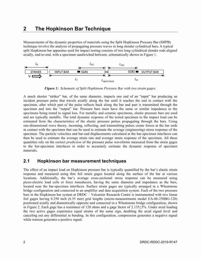
Figure 1: Schematic of Split Hopkinson Pressure Bar with two strain gages. . . . . . . . . . 2
Figure 2: Wheatstone bridge configuration and linear foil gage alignment on the Hopkinson bars at DRDC – Valcartier Research Centre. . . . . . . . . . . . . . . . . . . . . 3
Figure 3: The various forms of drift between two data sets observed in static calibration of strain gages . . . . . . . . . . . . . . . . . . . . . . . . . . . . . . . . . 4
Figure 4: Expanded view of a split Hopkinson bar showing the direction of forces, velocities, displacements and the prediction of typical strain signal pulses from the location of the strain gage to the bar-specimen interface. . . . . . . . . . . . . . . . . . . . 7
Figure 5: Free body diagram of a one dimensional bar element showing stresses acting on each face of the element . . . . . . . . . . . . . . . . . . . . . . . . . . . . 8
Figure 6: Resultsof a dynamic calibration of the Hopkinson bar system at 15 m/s. . . . . . . . 21
Figure 7: Strain signals measured from input and output bar strain gages in a test of AA 6061-T6 impacted at 17.6 m/s. . . . . . . . . . . . . . . . . . . . . . . . . . . . 22
Figure 8: Amplitude spectrum of strain signals from a test of AA 6061-T6 impacted at 17.6 m/s. 23
Figure 9: Effect of dispersion on dilatational phase velocity of pressure waves in maraging steel pressure bars based on bar radius, for Poisson’s ratio = 0.3. . . . . . . . . . . . . 24
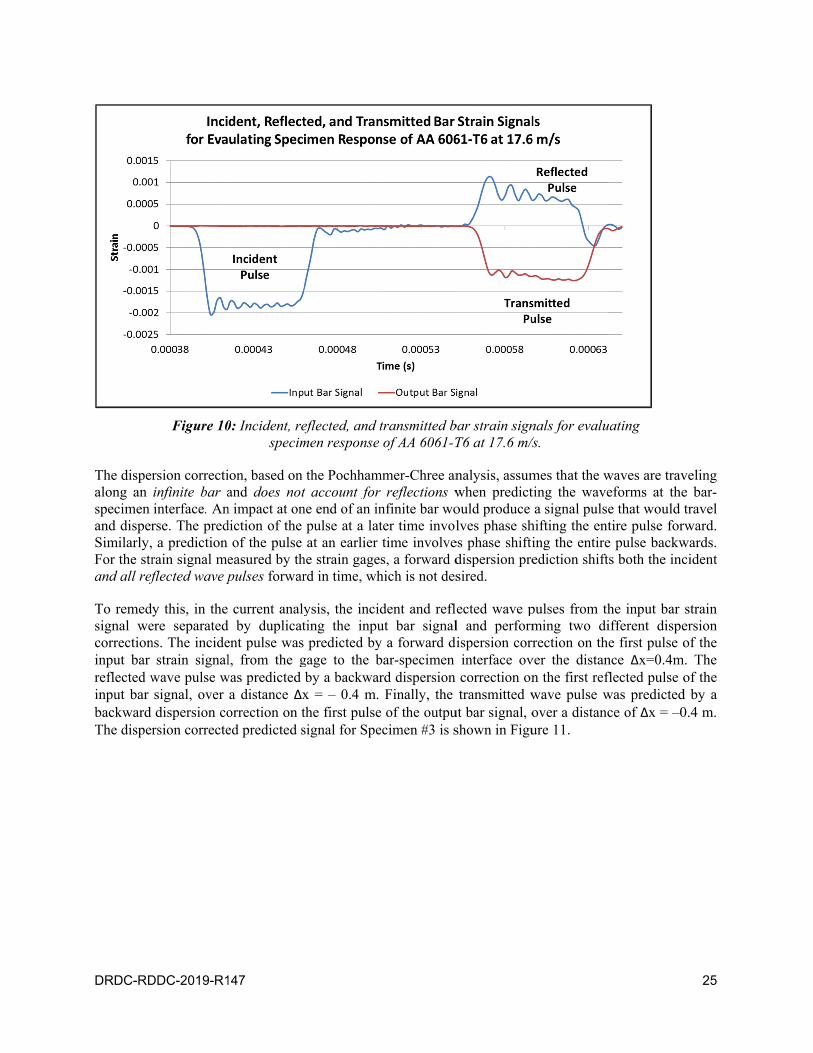
Figure 10: Incident, reflected, and transmitted bar strain signals for evaluating specimen response of AA 6061-T6 at 17.6 m/s. . . . . . . . . . . . . . . . . . . . . . . . . 25
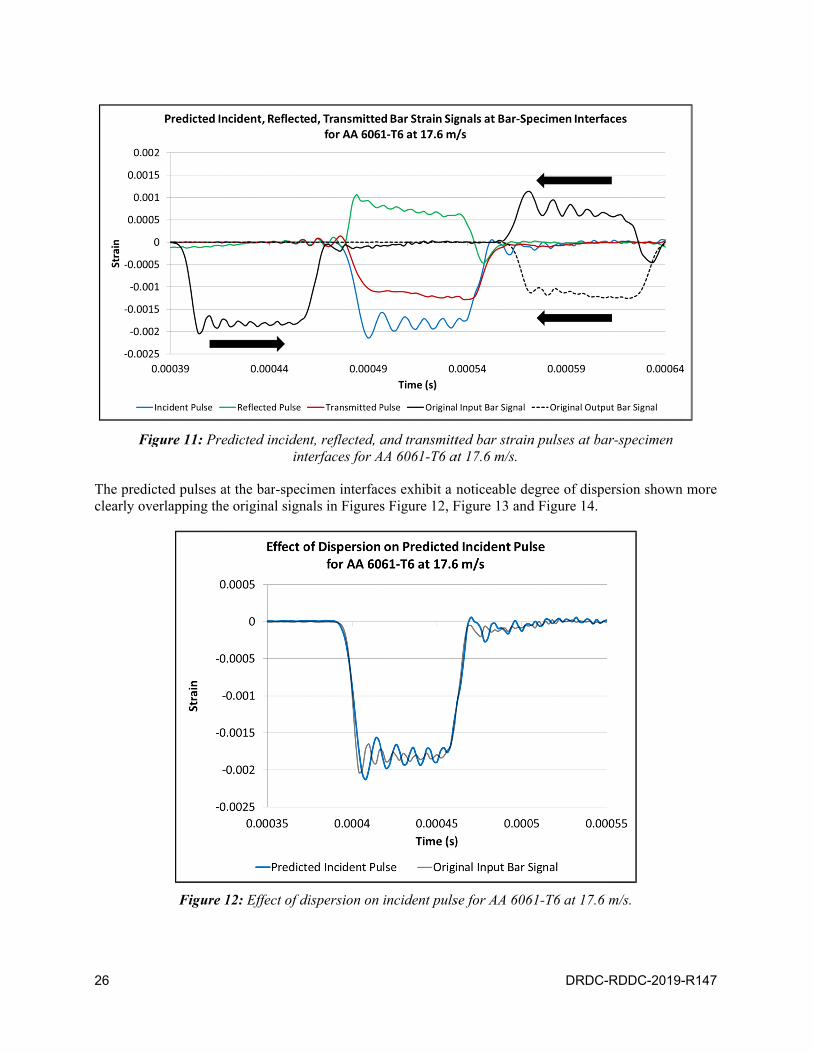
Figure 11: Predicted incident, reflected, and transmitted bar strain pulses at bar-specimen interfaces for AA 6061-T6 at 17.6 m/s. . . . . . . . . . . . . . . . . . . . . 26
Figure 12: Effect of dispersion on incident pulse for AA 6061-T6 at 17.6 m/s. . . . . . . . . 26
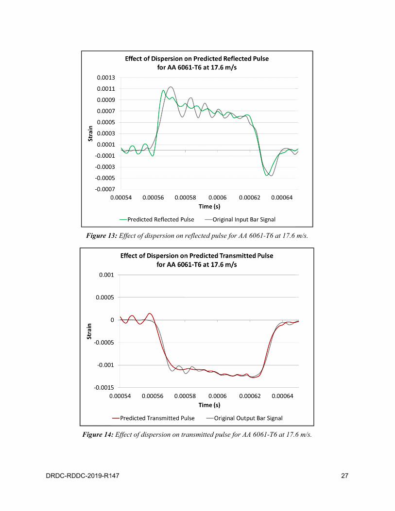
Figure 13: Effect of dispersion on reflected pulse for AA 6061-T6 at 17.6 m/s. . . . . . . . . 27
Figure 14: Effect of dispersion on transmitted pulse for AA 6061-T6 at 17.6 m/s. . . . . . . . 27
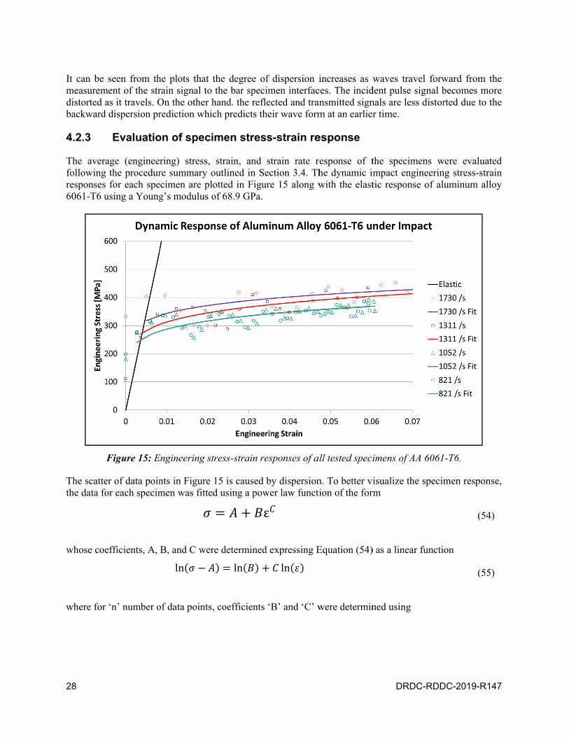
Figure 15: Engineering stress-strain responses of all tested specimens of AA 6061-T6. . . . . . 28
Figure 16: Effect of varying the cutoff frequency on the attenuation of the input bar voltage signal of Specimen #3 using a critically-damped recursive low-pass filter with 50 passes. . . 30
Figure 17: Effect of critically-damped filtering on the attenuation of the stress-strain response of Specimen #3 showing an overestimation of the yield point as cut-off frequency is decreased. . . . . . . . . . . . . . . . . . . . . . . . . . . . . . . . . 31

DRDC-RDDC-2019-R147 v
List of tables
Table 1: Experimental parameters for testing AA 6061-T6. . . . . . . . . . . . . . . . 20
Table 2: Static calibration of strain gages on split Hopkinson bar at DRDC – Valcartier Research Centre. . . . . . . . . . . . . . . . . . . . . . . . . . . . . . 21
Table 3: Static calibration coefficients used to correct strain signal. . . . . . . . . . . . . 21
Table 4: Fitting function coefficients for evaluating phase velocities of pressure waves in maraging steel bars with a Poisson’s ratio of 0.3 as a function of wavelength, and bar radius. . . . . . . . . . . . . . . . . . . . . . . . . . . . . . . . . . 24

vi DRDC-RDDC-2019-R147
Acknowledgements
The author would like to thank Luc Légaré for his assistance in calibration, testing, and troubleshooting on the split Hopkinson pressure bar system at DRDC – Valcartier Research Centre.
DRDC-RDDC-2019-R147 1
1 Introduction
A necessary step in designing structures and components for defense applications is characterizing the behavior of the material components under dynamic loading and shock. High strength armor materials, such as metallic alloys and ceramics, are designed to withstand high rates of deformation ranging from blast loading to projectile impact. The popular Split Hopkinson Pressure Bar (SHPB) technique, developed by Kolsky [1], was created from the need to reliably quantify the dynamic response of materials under extreme loading conditions by confining all the energy of impact and the propagation of pressure waves to one-dimension through long slender elastic pressure bars. By placing a much shorter cylindrical specimen between two pressure bars, end-to-end, and impacting one end of the bars, it was possible to estimate the dynamic stress and strain response of the specimen under uni-axial impact based upon the characteristics of the pressure waves propagating through the bars. The experimental technique is limited to impact forces that do not plastically deform the bars so that the bars remain elastic throughout testing and the specimen deforms uniformly. Since its inception the Hopkinson bar technique has been modified to test other modes of deformation including tension and torsion.
The SHPB was originally designed to operate at impact velocities producing low to moderate strain rates of deformation (102–103/s) so that wave propagation through the pressure bars can be assumed one-dimensional and errors due to dispersion effects neglected. However, at higher strain rates (103–104/s), often measured during blast loading or high speed projectile impact, high frequency vibrations are produced within the bars. The phase velocities of these frequency components do not travel at the fundamental speed of sound in the bar material, but decrease with increasing frequency of vibration creating phase lag as the pressure waves propagate along the bar. This phase lag is often referred to as dilatational (longitudinal) phase velocity dispersion and is a function of the bar Poisson’s ratio, diameter, distance traveled, and wavelength or frequency of vibration. Additionally, as the wavelengths of the higher frequency components approach the bar lateral dimension, radial inertia effects produce a variation in the stress and strain response through the cross-section of the bars, even for a uniformly applied impact load. Increasing the force of impact typically increases dispersion in the bars while increasing the bar diameter reduces dispersion, by reducing vibration, but at the cost of losing one-dimensional propagation and producing radial (distortional) dispersion. It therefore becomes necessary to correct for these distortion effects when predicting the wave form at any location in the bar and is an integral step towards reliably characterizing the dynamic response of tested specimens using the Hopkinson bar technique.
This paper reviews the procedure for predicting the propagation of pressure waves in elastic pressure bars using spectral wave analysis while correcting for dispersion and radial inertia effects. The procedure is then implemented to characterize the dynamic response of specimens of aluminum alloy 6061-T6 using the Split Hopkinson Pressure Bar system at DRDC – Valcartier Research Centre. Validation of the procedure is carried out by comparison with results from the literature.
2
2 T
Measuremtechnique split Hopkaxially, en
A much sincident pspecimen,specimen specimensand are tyestimated one-dimenin contactspecimen.then be uquantities to the bamaterials.
2.1
The effectresponse locations. piezo-eleclocated nebridge conbars in thefoil gagespositionedin Figure the two acanceling while tens
The Hop
ments of the dyinvolve the a
kinson bar appnd-to-end, wit
Figure 1
shorter “strikpressure pulse, after which and into the
s being testedypically metal
from the chnsional wave t with the spe. The particle sed to estimarely on the c
ar-specimen i
Hopkinso
t of an impacand measure
Additionallyctric load celear the bar-spnfiguration ane Hopkinson s having 0.25d axially and 2. Each gage
active gages out any diffe
sion generates
kinson B
ynamic propeanalysis of proparatus used fth a specimen
1: Schematic
ker” bar, of the that travelspart of the p
e “output” bad to signal losllic. The tota
haracteristics theory, incom
cimen that cavelocities an
ate the averagcorrect predicinterfaces in
on bar me
ct load on Hoed using thiny, the bar’s lls or force tpecimen intend connected bar system at
50 inch (6.35diametrically has a resistaexperience e
erential in bes a positive si
Bar Tech
erties of mateopagating prefor impact tes
n sandwiched
of Split Hopk
he same diams axially alonpulse reflectsar. Pressure ss. For metalll dynamic reof the elasti
ming, reflectian be used to nd bar-end disge strain ratection of the pr
order to ac
easureme
opkinson presn foil strain
average crotransducers, h
erfaces. Surfato an amplifi
t DRDC – Va5 mm) grid ley opposite andance of 120 ohequal strains nding. In thisignal.
hnique
erials using thessure waves sting consistsbetween, sch
kinson Pressu
meter, impactng the bar uns back along bars must halic and ceramsponse of theic pressure ping, and transestimate the
splacements cand average
ressure pulseccurately esti
ent techn
sure bar is tygages locateoss-sectional having the s
ace strain gagfier and data aalcartier Reseengths (microd connected inhms and a gaof the same
s configuratio
he Split Hopkiin long slend
s of two long hematically sh
ure Bar with t
ts one end ountil it reache
the bar and ave the same
mic specimense tested specipulses propagsmitting pulseaverage (eng
calculated at te strain respoe waveforms mimate the dy
niques
ypically quantd along the
stress resposame diameteges are typicacquisition syearch Centre o-measuremen a Wheatsto
age factor of 2e sign, doublon, compress
DRDC-
inson Pressurder cylindricalcylindrical slhown in Figur
two strain gag
of an “input” es the end inpart is transme or similar s, elastic presimen to the imgating througes create forc
gineering) strethe bar-specim
onse of the spmeasured froynamic respo
tified by the surface of t
onse can beer and impedally arranged
ystem. Each ois instrument
ents model EAone bridge con2.135+5%. Uling the axialion generates
RDDC-2019-
re Bar (SHPBl bars. A typicender rods alire 1.
ges.
bar producinn contact witmitted througimpedence t
ssure bars arempact load c
gh the bars. Uces at the baress response omen interfacepecimen. All m the strain gonse of spec
bar’s elastic the bar at vae measured dance as the d in a Wheatof the two preted with two lA-06-250BGnfiguration, s
Under axial lol signal leves a negative s
-R147
B) cal igned
ng an th the gh the to the e used an be Using r ends of the es can these gages cimen
strain arious using bars,
tstone essure linear
G-120) hown ading
el and signal

DRDC-RD
Figure
The strainconfigurat
where ‘Ve
of the stracontain th
Each straipressure pway that eThis requcorresponof the inpuduration ovelocity (material a
2.1.1
In any Whmeasuremresistancefunction obut growsconfigurat
DDC-2019-R1
e 2: Wheatston
n response in tion in Figure
exc’ is the bridain gage in Vhe error from t
in gage statiopulse at specieach travelinguires that thding gages onut and outputof a pulse indor speed of
and ‘ρ’ is its d
Strain-ga
heatstone bridment of the
s, and there of the resistan significantlytion in Figure
147
ne bridge conD
the bars is cae 2, the strain
dge excitation Volts, and ‘GF
the gage facto
on provides aifc locations ag and reflectinhe minimumn each bar bet bars must beduced by a ssound in the
density.
age non-lin
dge configuravoltage signare certain conce changes py at higher strae 2 can be ma
nfiguration anDRDC – Valca
alculated fromis calculated
voltage in VF’ is the gage or of the gage
a window ofalong the barng pulse can b
m linear diste greater or eqe greater or eqstriker is app
bar), C0=(Eb
nearity corr
ation there exnal, the bridgonditions undproducing thaains [2]. A code using Equ
nd linear foil artier Researc
m the change iusing Equatio
olts, ‘Ag’ is thfactor of the
es.
f measuremenrs. The split Hbe measured tance betweequal to the lenqual to twice roximately ebar/ρ)0.5 where
rection
xists a non-linge circuit bder which theat output. Thiorrection for sation (2), exp
0
01
gage alignmech Centre.
in voltage meon (1), expres
he amplifier ge strain gages
nt of the barHopkinson baand identifieden the bar-ngth of the stthe length ofqual to twicee ‘Ebar’ is the
nearity error. Tecomes unbae output of this error is smstrain non-linpressed as
ent on the Hop
easured by thssed as
gain, ‘V0’ is ts. Each strain
r strain respoar system is dd clearly with-specimen intriker. Additif the striker. Te its length de Young’s m
This error ocalanced by he bridge circ
mall for elastiearity of the W
opkinson bars
he gages. Usin
the voltage recalculation w
onse to a travdesigned in shout superposnterfaces andonally, the leThis is becausdivided by th
modulus of th
curs because the varying cuit is a nonlc strains in mWheatstone b
3
at
ng the
ading would
veling uch a
sition. d the engths se the
he bar he bar
upon gage
linear metals bridge
(1)
4
and notingbridge is gage factogives a ccorrected compressitoo high [during sta
2.1.2
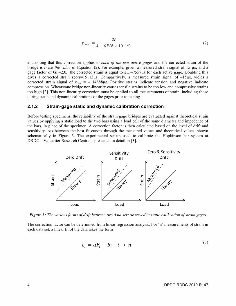
Before tesvalues by the bars, isensitivityschematicDRDC – V
Figure 3
The correceach data
g that this cotwice the valor of GF=2.0orrected strastrain signal
ion. Wheatsto[2]. This non-atic and dynam
Strain-ga
sting specimeapplying a st
in place of thy loss betweecally in FiguValcartier Re
3: The various
ction factor cset, a linear f
orrection applue of Equati, the correct
ain εcorr=151l of εcorr = –
one bridge no-linearity corrmic calibratio
age static a
ens, the reliabtatic load to t
he specimen. en the best fire 3. The exsearch Centre
s forms of drif
an be determifit of the data
plies to each on (2). For eted strain is e113με. Comp– 14888με. Pn-linearity carection must bns of the gag
and dynam
bility of the stthe two bars uA correctiont curves throxperimental se is presented
ft between tw
ined from lintakes the form
4
of the two aexample, giveequal to εcorr=paritively, a mPositive strai
auses tensile sbe applied toes prior to tes
mic calibrat
train gage briusing a load
n factor is theough the measet-up used
d in detail in [3
wo data sets ob
ear regressionm
2 10 12
; →
active gages aen a measure=7557με for emeasured strins indicate strains to be to all measuremsting.
tion correc
idges are evacell of the sa
en calculated asured values to calibrate 3].
bserved in sta
n analysis. Fo
DRDC-
and the corred strain signa
each active garain signal otension and
too low and cments of strai
ction
luated againsame diameter
based on theand theoretithe Hopkins
atic calibratio
or ‘n’ measur
RDDC-2019-
ected strain oal of 15 µε, age. Doublingf –15µε, yienegative ind
ompressive sin, including
st theoretical and impeden
e level of drifical values, sson bar syste
on of strain ga
ements of stra
-R147
of the and a g this
elds a dicate trains those
strain nce of ft and hown em at
ages
ain in
(2)
(3)

DRDC-RDDC-2019-R147 5
for I = 1,…n, where ‘ε’ is the strain and ‘F’ is the load. The coefficients ‘a’ and ‘b’ are determined by minimizing the squares of the vertical deviations, expressed as
of a set of ‘n’ data points based on the condition
The coefficients ‘a’ and ‘b’ are then determined for both the theoretical data set and the measured set by Equations (6) and (7), expressed as
and
At any load, ‘F’, the corrected strain can be calculated using Equation (8), expressed as
A dynamic calibration of the bars and load cell can also be performed, which involves measuring the difference between amplitudes of the incident pulses and the load cell. Any scalar difference is calculated as a % error and added to the correction in Equation (8).
(4)
(5)
(6)
(7)
(8)
2 , ≡ 2
1
2
0.
∑ 1 ∑ 1 ∑ 1
∑ 21 ∑ 1
2
∑ 1 ∑ 21 ∑ 1 ∑ 1
∑ 21 ∑ 1
2
6 DRDC-RDDC-2019-R147
2.1.3 Strain-gage attenuation correction based on gage length
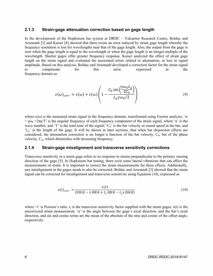
In the development of the Hopkinson bar system at DRDC – Valcartier Research Centre, Bolduc and Arsenault [3] and Kaiser [4] showed that there exists an error induced by strain gage length whereby the frequency resolution is lost for wavelengths near that of the gage length. Also, the output from the gage is zero when the gage length is equal to the wavelength or when the gage length is an integer multiple of the wavelength. Shorter gages offer greater frequency response. Kaiser analyzed the effect of strain gage length on the strain signal and evaluated the associated errors related to attenuation, or loss in signal amplitude. Based on this analysis, Bolduc and Arsenault developed a correction factor for the strain signal to compensate for this error, expressed in the frequency-domain as
where ε(ω) is the measured strain signal in the frequency-domain, transformed using Fourier analysis; ‘ω = γω0 =2πγ/T’ is the angular frequency of each frequency component of the strain signal, where ‘γ’ is the wave number, and ‘T’ is the total time of the signal; ‘C0’ is the bar velocity or sound speed in the bar, and ‘Lg’ is the length of the gage. It will be shown in later sections, that when bar dispersion effects are considered, the attenuation correction is no longer a function of the bar velocity, C0, but of the phase velocity, Cω, which diminishes with increasing frequency.
2.1.4 Strain-gage misalignment and transverse sensitivity corrections
Transverse sensitivity in a strain gage refers to its response to strains perpendicular to the primary sensing direction of the gage [5]. In Hopkinson bar testing, there exist some lateral vibrations that can affect the measurements of strain. It is important to correct the strain measurements for these effects. Additionally, any misalignment in the gages needs to also be corrected. Bolduc and Arsenault [3] showed that the strain signal can be corrected for misalignment and transverse sensitivity using Equation (10), expressed as
where ‘ν’ is Poisson’s ratio, ts is the transverse sensitivity factor supplied with the strain gages, ε(t) is the uncorrected strain measurement, ‘α’ is the angle between the gage’s axial direction, and the bar’s axial direction, and sin and cosine terms are the mean of the absolute of the sine and cosine of the offset angle, respectively.
(9)
(10)
10 sin
02 0
0 2⁄
cos sin sin cos

DRDC-RD
2.2 S
In additionassumes wmeaning tsignals at amount eqfundamen
In a Splitresponse sexpanded-and transmtensile and
Figdisplacem
The predigage and shifted in by the barinterface, interface balso blenddifficult to
DDC-2019-R1
Specime
n to the requiwave propagthat the straithe bar-spec
qual to to the ntal speed of s
t Hopkinson showing the i- view schemmitted strain pd shown as po
gure 4: Expanments and the
icted temporathe bar-specimtime equal to
r velocity, C0.shown in Fi
because the ind with other ro identify the
147
n respon
irement that tgation is onen measureme
cimen interfaclinear distan
sound in the b
Pressure Barncident, refle
matic in Figurpulses are in ositive.
nded view of aprediction of
al positions ofmen interfaceo the distance. It is importaigure 4, are nncident wave eflecting sign
e individual pu
nse in a H
the metallic be-dimensionalents at any lce. The stresce from the s
bar, or bar vel
r system witected, and trane 4, showing compression
a split Hopkinf typical strain
bar-spe
f the strain pue. If bar distoes of the straiant to note alsnot the sameand reflected
nals from the ulses. This w
Hopkinson
bars remain ell and often ocation along
ss or strain sistrain gages tolocity.
th one strain nsmitted pulse
the bar-endsand are show
nson bar shown signal pulsecimen interfa
ulses are depeortion effects in gages to tho that the pre
e as a signal d waves woulspecimen, giv
would also vio
n Bar Sys
lastic during tdispersion a
g the bar areignals can simo the bar-spec
gage stationes, at specific
s in contact wwn as a negati
wing the direces from the loace.
endent on theare ignored,
he specimen iedicted signal
measured byld not only suving incorrec
olate the desig
stem
testing, Hopkand attenuatie a good repmply be shifcimen interfa
n on each bac locations, iswith the speciive, while the
ction of forcesocation of the
e linear distanthe predicted
interfaces, LG
s at the first iy a strain gauperimpose upct signal readign considerat
kinson bar anaon are negle
presentation ofted in time baces divided b
ar, a typical s represented iimen. The ince reflected pu
s, velocities, strain gage t
nce between d pulses are siGI and LGO, diinput bar/specage located apon each otheings and maktions of the S
7
alysis ected, of the by an by the
strain in the cident ulse is
to the
strain imply vided cimen at this er but
king it HPB.
8
Clearly idaccurately
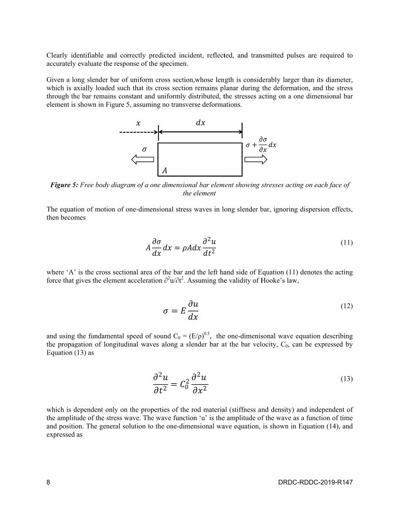
Given a lowhich is athrough thelement is
Figure 5
The equatthen becom
where ‘A’force that
and usingthe propagEquation (
which is dthe amplitand positiexpressed
dentifiable any evaluate the
ong slender baxially loadedhe bar remains shown in Fig
5: Free body d
tion of motionmes
’ is the cross gives the elem
the fundamegation of lon(13) as
dependent ontude of the stron. The geneas
nd correctly p response of t
bar of uniformd such that itns constant angure 5, assum
diagram of a
n of one-dim
sectional areament accelera
ental speed ofngitudinal wav
nly on the proress wave. Theral solution t
predicted incthe specimen.
m cross sectiots cross sectiond uniformly
ming no transv
one dimensioth
ensional stres
a of the bar aation ∂2u/∂t2.
f sound C0 = ves along a s
operties of thehe wave functto the one-dim
2
2 02
cident, reflect.
on,whose lenon remains pldistributed, t
verse deforma
onal bar elemhe element
ss waves in lo
and the left haAssuming the
(E/ρ)0.5, theslender bar a
e rod materiation ‘u’ is themensional wa
2
2
02
2 2
ted, and tran
ngth is considlanar during the stresses aations.
ent showing s
ong slender b
and side of Ee validity of H
e one-dimenisat the bar vel
al (stiffness ane amplitude ofave equation,
DRDC-
nsmitted pulse
derably largerthe deformatcting on a on
stresses actin
bar, ignoring
Equation (11) Hooke’s law,
sonal wave eqocity, C0, can
nd density) af the wave as is shown in E
RDDC-2019-
es are requir
r than its diamtion, and the ne dimensiona
ng on each fac
dispersion ef
denotes the a
quation descrn be expresse
and independea function of
Equation (14)
-R147
red to
meter, stress al bar
ce of
ffects,
acting
ribing ed by
ent of f time ), and
(11)
(12)
(13)

DRDC-RDDC-2019-R147 9
having the properties,
where ‘f’ and ‘g’ are arbitrary functions describing the shape of the propagating wave. The function ‘f’ corresponds to a forward traveling wave in the positive x direction; while function ‘g’ corresponds to a wave traveling backward in the negative x direction, and can be thought of as a reflected wave. The strain in the bar can be derived as a function of the forward and backward traveling strain pulses by taking the partial derivative of Equation (14) with respect to x, as
The particle velocity, or the velocity at which a single point within the bar moves as the wave passes through it, can be derived from Equation (13), and Hooke’s laws as,
Particle velocities depend on the applied loading while the wave velocities, or phase velocities, are an intrinsic material property. From Equation (11) and (13), the particle forces in bar can be expressed as
In a Hopkinson bar system using elastic pressure bars, the instantaneous forces at each bar-end in contact with the specimen can be expressed using Equation (18) as
(14)
(15)
(16)
(17)
(18)
, 0 0
0 0
2
2 02
2
2 02
2
2
, , ,
, 0 0 0 0 , ,
,2
2
2
2
2
2 , ,

10 DRDC-RDDC-2019-R147
where Abar is the cross sectional area of the bar, and ‘Ebar’ is the Young’s modulus. Each bar contains forward and backward traveling waves denoted as incident (forward) and reflected (backward) in the input bar and transmitted (forward) in the output bar. The average (engineering) stress response of the specimen can be evaluated by taking the average of the forces at the two bar-ends in contact with the specimen on the face of the specimen, expressed in Equation (20), as
where Aspec is the cross sectional area of the specimen. The engineering strain rate response in the specimen can be evaluated as a function of the difference between the particle velocities determined at each bar-specimen interface, shown in Equation (21), as
and the engineering strain can be evaluated by taking the integral of the strain rate with respect to time, expressed in Equation (22), as
The true strain and strain rate in the material can be determined using high speed imaging or digital image correlation techniques to measure the instantaneous change length and cross-sectional area of the specimen during deformation. The true strain response of a specimen can be evaluated using Equation (23), expressed as
(19)
(20)
(21)
(22)
2⁄
2
2
⁄ 0
⁄ 0
0
DRDC-RDDC-2019-R147 11
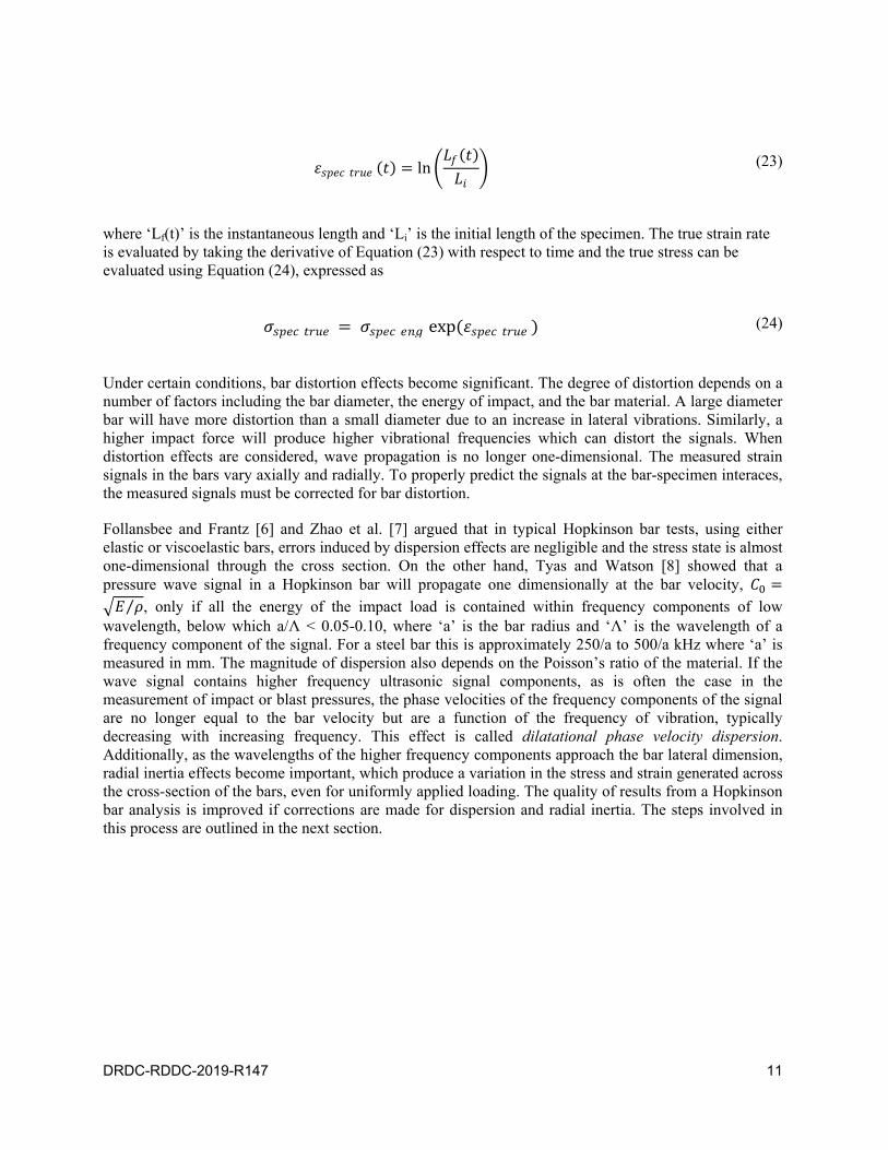
where ‘Lf(t)’ is the instantaneous length and ‘Li’ is the initial length of the specimen. The true strain rate is evaluated by taking the derivative of Equation (23) with respect to time and the true stress can be evaluated using Equation (24), expressed as
(23)
(24)
ln
exp
Under certain conditions, bar distortion effects become significant. The degree of distortion depends on a number of factors including the bar diameter, the energy of impact, and the bar material. A large diameter bar will have more distortion than a small diameter due to an increase in lateral vibrations. Similarly, a higher impact force will produce higher vibrational frequencies which can distort the signals. When distortion effects are considered, wave propagation is no longer one-dimensional. The measured strain signals in the bars vary axially and radially. To properly predict the signals at the bar-specimen interaces, the measured signals must be corrected for bar distortion.
Follansbee and Frantz [6] and Zhao et al. [7] argued that in typical Hopkinson bar tests, using either elastic or viscoelastic bars, errors induced by dispersion effects are negligible and the stress state is almost one-dimensional through the cross section. On the other hand, Tyas and Watson [8] showed that a pressure wave signal in a Hopkinson bar will propagate one dimensionally at the bar velocity,
⁄ , only if all the energy of the impact load is contained within frequency components of low wavelength, below which a/Λ < 0.05-0.10, where ‘a’ is the bar radius and ‘Λ’ is the wavelength of a frequency component of the signal. For a steel bar this is approximately 250/a to 500/a kHz where ‘a’ is measured in mm. The magnitude of dispersion also depends on the Poisson’s ratio of the material. If the wave signal contains higher frequency ultrasonic signal components, as is often the case in the measurement of impact or blast pressures, the phase velocities of the frequency components of the signal are no longer equal to the bar velocity but are a function of the frequency of vibration, typically decreasing with increasing frequency. This effect is called dilatational phase velocity dispersion. Additionally, as the wavelengths of the higher frequency components approach the bar lateral dimension, radial inertia effects become important, which produce a variation in the stress and strain generated across the cross-section of the bars, even for uniformly applied loading. The quality of results from a Hopkinson bar analysis is improved if corrections are made for dispersion and radial inertia. The steps involved in this process are outlined in the next section.

12 DRDC-RDDC-2019-R147
3 Hopkinson bar distortion effects and corrections
Two major sources of distortion in Hopkinson bars are longitudinal (or dilatational) phase velocity dispersion and radial inertia effects whereby the signals disperse axially and radially and wave propagation is no longer one-dimensional. In Hopkinson bar analysis, dispersion refers to the lateral “widening” of a signal or wave as it propagates axially. At the same time, the signal may attenuate where its amplitude or the amplitude of its frequency components diminishes. Attenuation is especially significant in viscoelastic bar materials, which act as acoustic dampeners. The phase velocities of the frequency components of a pressure wave signal affected by dispersion are no longer equal to the bar velocity but diminish with increasing frequency, the degree of which is dependent on the bar diameter, Poisson’s ratio, and wavelength of the frequency components. Additionally, at some higher frequencies, radial inertia produces a variation in the stress and strain generated across the cross-section of the bars, even for a uniformly applied load, such that any strain measurements at the bar surface are not the same as along the axis. Thus, it becomes necessary to correct a strain signal both for longitudinal dispersion and radial inertia if it is to be predicted correctly from the strain gage reading to the specimen-bar interface. Both phase velocity dispersion and radial inertia effect corrections are applied to the measured signals in the frequency domain using discrete Fourier analysis.
This section provides the theory and procedure for correctly predicting the stress and strain signals at any location in the bars, while correcting bar distortion effects.
3.1 Spectral wave analysis using the Discrete-Time Fourier Transform (DTFT)
Spectral wave analysis is the analysis of waves in terms of their spectrum of frequencies. When used to analyze wave propagation in pressure bars, it provides a way to shift a signal in time or spacial location while accounting for dispersion and radial inertia effects by altering the phase angles and amplitudes of the frequency components of the signal. A strain signal measured as a function of time, can be expressed as the sum of harmonic waves using a Discrete-Time Fourier Transformation (DTFT) formula by converting it to the the frequency domain, shown in Equation (25) as
(25)
where ‘ω=γω0’ is the angular frequency of each frequency component of the wave signal, ‘γ’ is the wave number in the frequency domain, ‘ω0=2π/T’ is the fundamental angular frequency, ‘T’ is the total time of the signal, ‘N’ is the total number of time increments or strain data readings, and ‘Δt=T/N’ is the time increment. A sampling rate of ‘N/2T’ is chosen to limit a distortion typically associated with this transformation called aliasing, which results in differences between the original signal and the reconstructed one at higher frequencies. This is called the Nyquist sampling frequency or Nyquist criterion. As a result the reliable frequency-domain signal is limited to N/2 frequencies. The phase angle and amplitude of the frequency-domain strain signals are
0
∙ 0 ∆ ∙ 0 ∆ ∙ 0 ∆0
DRDC-RDDC-2019-R147 13
(26)
and
(27)
The frequency domain strain signal can also be expressed using its amplitude and phase angle as
(28)
Any corrections for dispersion and radial inertia effects are made to the amplitude and the phase angle of each frequency component prior to converting back to the time-domain using the Inverse Discrete-Time Fourier Transform (IDTFT), expressed in Equation (29), as
(29)
Typically, only the real portion of the bar strain signal is useful in characterizing the test material and imaginary portions are ignored. The real portion of Equation (29) is expressed as
(30)
The values determined by Equation (30) represent the distortion corrected strain signal at the bar-specimen interface. It will be shown that dispersion corrections are made by shifting the phase angle of each frequency component, φ, by an amount dependent on the the phase velocity and distance between the strain gages and the bar-specimen interfaces. Radial inertia effect corrections are made to the amplitude of the signals |ε(ω)|.
PhaseAngle arg atan2
Amplitude/2
2 2
/2
cos sin
2
∙ 0 ∆
2⁄
0
2 cos sin ∙ 0 ∆
2⁄
0
2 cos sin ∙ cos 0 ∆ sin 0 ∆
2⁄
0
2 cos 0 ∆ sin 0 ∆
/2
0
2 cos cos 0 ∆ sin sin 0 ∆
/2
0
14 DRDC-RDDC-2019-R147
3.2 Phase velocity dispersion correction
The effect of distortion on pressure waves in long slender bars has been studied and analyzed over many years. Several algorithms to correct for distortion effects have been developed and continue to be improved upon for several bar materials in order to expand the capabilities of the Hopkinson bar technique. For elastic bars, these analyses are based upon the closed form solution of the Pochhammer-Chree equation of motion for infinitely long bars, despite it not being strictly valid for analysis of transient pulses in finite bars but far more computationally efficient than numerical solutions. Pochhammer (1876) [9] and Chree (1889) [10] independently developed solutions of equations of motion for idealized cases of infinitely long bars subjected to forcing functions of infinite duration. Love (1934) [11] was the first to develop a frequency equation by transforming the three-dimensional Pochhammer-Chree equation of motion of a solid circular rod into cylindrical coordinates and applying traction-freesurface boundary conditions. Bancroft (1941) [12] solved Love’s frequency equation numerically for thefirst root differing from zero, referring to the first mode of vibration (longitudinal wave propagation). Hissolution relates dilatational phase velocity to bar radius and wavelength of frequency components forPoisson’s ratios ranging between 0.1 and 0.4. The second and third roots of the Pochhammer-Chreefrequency equation correspond to the second mode of vibration (distortional) and third mode of vibration(Rayleigh surface wave propagation), respectively. From Bancroft [12], the frequency equation, derivedby Love [11] takes the form,
(31)
where
(32)
and ‘µ’ is the shear modulus or modulus of rigidity of the bar material, ‘E’ is Young’s modulus, ‘v’ is Poisson’s ratio, ‘λ’ is Lame’s first parameter, ‘ρ’ is the density of the bar material, ‘a’ is the bar radius, ‘Cω’ and ‘Ct’ are the dilatational and shear (transverse) phase velocities of the frequency components in an infinite bar, ‘C0’ is the bar velocity or fundamental sound speed in the bar, Λ=(2π/γ) is the wavelength of the frequency components, and ‘Jn’ defines a Bessel function of the first kind of order ‘n’. Bancroft simplified Love’s equation to
2202 2
J0 2 1
2 0 2 22
1
0,
1 ,
2 1 ,
1 2 1⁄ ,
0
2
1 ,
2 ⁄ ⁄ ,
⁄ ,
0 ⁄ ,
0.5 1⁄ ,
DRDC-RDDC-2019-R147 15
(33)
where
(34)
The first root of Equation (33), differing from zero and solved explicitly for ‘x’ corresponds to the first mode vibration for the propagation of longitudinal waves. Bancroft computed the first roots for values 0 < γa < ∞ and for Poisson’s ratios 0.1 < ν 0.4 in increments of 0.05 and tabulated his results in [12]. Later Gong et al. [13] developed a fitting function, shown in Equation (35), that accurately predicts the phase velocity as a function of wavelength and bar radius and fits well the dispersion data computed by Bancroft. It is expressed by
(35)
where Cω/C0 is the normalized phase velocity, Λγ is the wavelength of the frequency component ‘γ’, ‘a’ is the bar radius, and A, B, C, D, E, and F are the coefficients derived for each Poisson’s ratio. These coefficients can be solved using regression analysis techniques.
From these analyses, Gorham (1983) [14] and Follansbee and Franz (1983) [6] were the first to to develop an algorithm to correctly predict dispersion of a traveling wave based on the first mode of the Pochhammer-Chree dispersion relation using a Hopkinson bar to test for ductile metallic materials. They showed that a properly dispersed waveform could be predicted at any location along the bar by applying a phase shift to each phase angle of the frequency components of the strain signal in the frequency domain, which is dependent on the phase velocity of each frequency component as well as the axial distance to shift the signal. The accuracy of this method was limited to moderately dispersed signals [8] [15], losing accuracy for highly dispersed signals due to the possibility that some of the energy of the signal carried by higher frequency components travels at higher modes. Li and Lambros [16] modified this method to better visualize the shift in the pressure pulse in both distance and time. This phase shift is expressed by Equation (36), as
(36)
where Δx is the axial distance—a positive value referring to a forward shift and a negative value referring to a backward shift. The phase shift represents the amount of dispersion produced in a frequency component of a signal traveling an axial distance of Δx along the bar. In Hopkinson bar analyses, Δx would be the distance between the strain gage and the bar-specimen interface. The dispersion corrected phase angle would then be calculated as
(37)
, , 1 2 1 0,
0
1
0Λ
4
Λ
3
Λ
2
Λ
1.5
1,
0∆
,
arg ,
16 DRDC-RDDC-2019-R147
where arg(εγ(ω)) is the phase angle of the strain signal in the frequency domain.
3.3 Radial inertia effects and prediction of axial bar stress and strain
In his extensive analysis of Hopkinson bars, Davies (1948) [17] discovered that at some higher frequencies, the lateral inertia in Hopkinson bars causes the magnitude of the stress to vary across the radial ordinate and that the ratio of the axial stress to axial strain (Young’s modulus) is not constant across the bar cross-section and varies with both frequency and radial ordinate. Davies developed equations to calculate the average stress and particle displacement over the bar cross section which were then analyzed by Tyas and Watson [8] who developed correction factors that transformed the surface strains to the average axial strain and then from the axial strain to the average axial stress. According to Davies, for an infinitely long rod subjected to a plane sinusoidal axial disturbance of infinite duration, at any time ‘t’ and at a location (x,r) where ‘x’ refers to the axial direction and ‘r’ refers to the radial direction, the axial stress, σxx, and particle displacement, ux, can be expressed as
(38)
and
(39)
where ‘A’ is a constant defining the magnitude of oscillation, ‘i=√ 1’, and
(40)
and
(41)
Davies pointed out that the values of f1 and f2 cannot be complex meaning that the particle velocities and displacements must be in the same phase or in antiphase at any instant at all points on the cross-section of the bar. Davies showed that the average values of particle velocity and axial stress could be derived using the average value of f1 and f2 over the bar cross-section as
(42)
and
2 2 11 ,
1 ,
1 1 0
1
11
0
1,
0
1
11
0
1.
1
22 1
02 1 2 1
1
1,
1
0
DRDC-RDDC-2019-R147 17
(43)
From Davies’ analysis, Tyas and Watson [8] derived two correction factors, M1(ω) , and M2(ω) , which are multiplied with the amplitude of each frequency component of the strain signal to convert the surface strain measured by the strain gages to the average axial strain and then to the average axial stress. The first correction factor, M1(ω), is essentially the ratio of the average axial strain over the bar cross section to the axial strain at the bar surface and the second correction factor, M2(ω), is the ratio of the average axial stress to the average axial strain for a given wavelength (equal to the dynamic elastic modulus of the bar). These factors are defined in Equations (44) and (45), as
(44)
and
(45)
The magnitudes of the average axial strain and stress are then calculated using Equations (46) and (47), expressed as
(46)
and
(47)
These magnitudes can then be used to construct the frequency domain average axial bar strain, shown in Equation (48), and average axial bar stress, shown in Equation (49), using the dispersion corrected phase angles from Equation (37), as
(48)
and
2
22 2
02 2 2 1
1
1.
1
0
1
2
2
2 1 11
0
1
11
0
1
2
2 2 11
2 2 12
0
2
.
| | 1 ω ,
| | 1 ω 2 ω .
1 1 cos 1 sin
18 DRDC-RDDC-2019-R147
(49)
From Equation (29), the average axial strain signal in the time domain, obtained by performing an Inverse Discrete-Time Fourier Transformation (IDTFT), is expressed as
(50)
And the stress signal is expressed as
(51)
where the real portions are expressed as
(52)
and
(53)
The average bar strain and stress values evaluated using Equations (52) and (53) represent the predicted and dispersion-corrected axial strain and stress response of the bar at the two bar-specimen interfaces, which can be used to evaluate the dynamic properties of the specimen using equations in Section 2.2.
1 2 1 2 cos 1 2 sin
2∙ 0 ∆
2⁄
0
21 ω cos sin cos 0 ∆ sin 0 ∆
2⁄
0
2∙ 0 ∆
2⁄
0
21 ω 2 ω cos sin cos 0 ∆ sin 0 ∆
2⁄
0
21 cos cos 0 Δ sin cos 0 Δ
/2
0
21 2 cos cos 0 Δ sin cos 0 Δ
/2
0

DRDC-RDDC-2019-R147 19
3.4 Summary of procedure
The following steps outline the procedure for analyzing experimental strain gage data, applying corrections, and evaluating the dynamic response of a specimen using spectral wave analysis —noting that the calibration and strain gage correction procedures specifically follow [3] and apply primarily to the elastic Hopkinson bar system at DRDC – Valcartier Research Centre:
1) Install and calibrate the strain gages: apply corrections as per in Section 2.1.
2) Perform impact tests and acquire strain gage data. Convert voltage to strain using Equation (1).
3) Apply time-domain strain-gage corrections: strain gage misalignment and transverse sensitivity corrections using Equation (10).
4) Apply frequency-domain strain gage corrections: Covert the time-domain bar strain signals, ε(t), to the frequency-domain, ε(ω), using the discrete Fourier transformation in Equation (25). Apply the attenuation correction for gage length to to ε(ω), using Equation (9). Then evaluate the amplitude and phase angle of each frequency component of corrected signal using Equations (26) and (27).
5) Determine the phase velocities, Cω, for each frequency component using the fitting function, in Equation (35), on Bancroft’s tables from [12] for the Poisson’s ratio of the bar material. Evaluate the fitting function’s coefficients using methods such as regression analysis.
6) Correct the phase angles for dispersion by evaluating the phase shifts for each frequency component using Equation (36) using a linear distance Δx equal to the distance between the strain gage and the bar-surface interface. Correct the phase angles, evaluated in step 4, by applying the phase shift to each frequency component using Equation (37).
7) Evaluate the average axial bar strain and stress to correct for radial inertia effects. Determine the amplitude correction factors M1(ω) and M2(ω) for each frequency component of the bar strain signals using Equations (44) and (45) and apply them to the surface strain signal amplitudes using Equations (48) and (49). Transform to the time domain and evaluate the real portion using Equations (52) and (53).
8) Evaluate the dispersion-corrected average stress response in the specimen using the calculated average axial bar stress for each pulse in Equation (20).
9) Evaluate the dispersion-corrected strain rate response in the specimen using the calculated average axial bar strain for each pulse in Equation (21).
10) Evaluate the dispersion-corrected strain response in the specimen using Equation (22).
11) Evaluate the true stress and strain values if instantaneous length and diameter measurements are available using Equations (23) and (24).

20 DRDC-RDDC-2019-R147
4 Characterization of aluminum alloy 6061-T6
A total of four impact tests were performed at various impact velocities on specimens of aluminum alloy 6061-T6 at room temperature using the split Hopkinson bar system at DRDC – Valcartier Research Centre. This alloy was chosen because of the extensive availability of impact data and is relatively strain rate insensitive up to approximately 1000/s [18]. The split Hopkinson bar system at DRDC – Valcartier Research Centre consists of two 800 mm long, 14.5 mm diameter maraging steel cylindrical bars; and a striker bar with the same diameter and a length of 15 mm. Each of the input and output bars are instrumented with two linear foil gages in the Wheatstone bridge configuration shown in Figure 2 as described in Section 2.1, and located midway (400 mm) across each bar. Cylindrical specimens were machined to a length of 5.00+0.02 mm and a diameter of 10.50+0.02 mm. The strain rate of deformation of each specimen was controlled by setting the air pressure of the system that propels the striker. Impact pressures were selected to achieve strain rates starting from approximately 1000/s and increasing in order to evaluate the strain rate sensitivity of the aluminum alloy. The strain rates were found to be very sensitive to the selected impact pressures. Impact velocities were recorded using an Enhanced Laser Velocity Sensor (ELVS) that reads the displacement of the striker during the last 25 mm of its travel, ending at the point of impact [3]. The experimental parameters are presented in Table 1 along with the calculated strain rates.
Table 1: Experimental parameters for testing AA 6061-T6.
Specimen # Input Pressure [psi]
Impact Velocity [m/s]
Average Strain Rate [/s]
1 13.5 16.2 821 2 13.6 16.9 1052 3 13.6 17.6 1311 4 13.8 19.1 1701
A detailed description of the Hopkinson bar system at DRDC Valcartier Research Centre and its components can be found in [3].
4.1 Strain-Gage Calibration and time-domain corrections
For all five tests, a static calibration was carried on the two bars with a load cell, each instrumented with the same wheatstone bridge configuration—the results of which are shown in Table 2. Voltage readings from the oscilloscope were converted to strain using Equation (1) carrying the 5% error from the gage factor and then non-linearity corrections were applied using Equation (2). Theoretical values of strain were calculated using Hooke’s law. The modulus of elasticity of the maraging steel bars is 190 GPa.
DRDC-RD
Applied [N] (l
0 (0890 (2
1779 (42669 (3559 (
0 (dri
The coeffsignal for
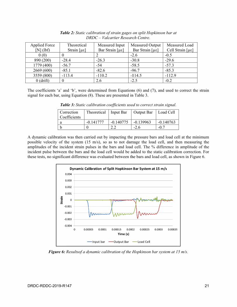
A dynamipossible vamplitudeincident pthese tests
DDC-2019-R1
Tab
Force lbf) 0) 0 200) -28400) -56600) -85800) -11ift) 0
ficients ‘a’ aneach bar, usin
Tab
CorrCoea b
ic calibration velocity of thes of the incidpulse betweens, no significa
Figure 6: R
147
ble 2: Static caD
Theoretical Strain [µε]
8.4 6.7 5.1 13.4
nd ‘b’, were dng Equation (
ble 3: Static ca
rection efficients
T
-00
was then carhe system (1dent strain pun the bars andant difference
Resultsof a dy
alibration of sDRDC – Valca
MeasureBar Stra
2 -26.3 -54 -82.6 -110.2 2.6
determined fr(8). These are
alibration coe
Theoretical
0.141777 2
rried out by im5 m/s), so asulses in the bd the load cel
was evaluate
ynamic calibr
strain gages oartier Researc
ed Input ain [µε]
MB
-2-3-5-9-1-2
rom Equatione presented in
efficients used
Input Bar
-0.140775 2.2
mpacting the s to not dam
bars and load l would be ad
ed between th
ration of the H
on split Hopkch Centre.
Measured OutpBar Strain [µ2.6 30.8 58.5 96.7 114.5 2.5
ns (6) and (7)n Table 3.
d to correct s
Output Bar
-0.139963 -2.6
pressure barmage the loadd cell. The % dded to the st
he bars and lo
Hopkinson ba
kinson bar at
tput ε]
MeasuCell S
-0.5 -29.6 -57.3 -85.3 -112.9 -0.2
), and used to
strain signal.
Load Cell
-0.140763 -0.7
s and load ced cell, and th
difference intatic calibratiad cell, as sho
ar system at 1
ured Load train [µε]
o correct the
ell at the minihen measurinn amplitude oion correctionown in Figure
15 m/s.
21
strain
imum ng the of the n. For e 6.

22
Strain gagbars usingtransversemaraging derived fr
4.2 S
Followingindicated non-linearfrequencygage attenvoltage sispectrum
ge misalignmeg a short metae sensitivity osteel bars is om the denom
Spectral
g calibration, in Table 1. Trity, misalign
y domain, usinnuation basedignals from thof the strain s
Figure 7
ent was elimiallic sleeve w
of each gage p0.30. Using E
minator of thi
wave ana
specimens ohe recorded v
nment and trang the discretd on gage lenhe impact tessignals is show
7: Strain signatest
inated by stenwith slotted hprovided by tEquation (10)s equation, w
alysis an
of aluminumvoltage-time dansverse sensite Fourier tranngth using Eqst of Specimewn in Figure
als measured ft of AA 6061-
nciling the looles in the shthe manufactu), a correction
was calculated
d frequen
m alloy 6061-data was convitivity. The tinsform formuquation (9). Aen #3 at 17.68.
from input anT6 impacted
ocation and orhape of the gurer was 0.7%n factor, appld to be 0.79.
ncy-dom
-T6 were tesverted to straime-domain dula in EquatioAn example o6 m/s is show
nd output barat 17.6 m/s.
DRDC-
rientation of gages that fit % and the Poilied to the me
ain corre
sted under imain and correcdata was thenon (25), and cof the raw inpwn in Figure
r strain gages
RDDC-2019-
the gages ontover the barsisson’s ratio oeasured strain
ections
mpacted velocted for strainn converted tcorrected for put and outpu
7. The ampl
s in a
-R147
to the s. The of the
ns and
ocities n gage to the strain ut bar litude

DRDC-RD
Figu
Accordingcontain hibar in DRDC – Vfrequencyin Figure bar and th
4.2.1
Dispersiondifferent pphase veldifferent lfrequency
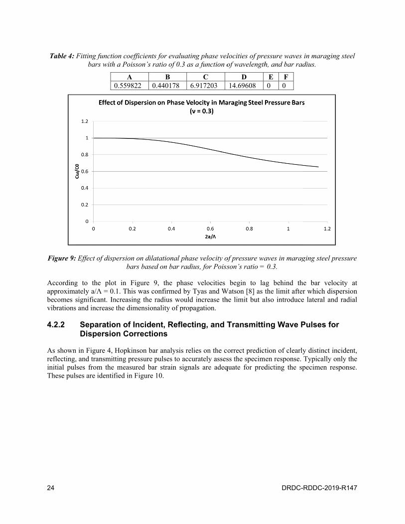
For each tfunction invarious Pofitting fun4. A plot oof dispersfrequencythe veloccompressi
DDC-2019-R1
ure 8: Amplitu
g to Tyas andigh frequency
mm. GiveValcartier Re
y range of 2208, indicates t
he strain signa
Evaluatio
n in pressure phase velocitiocities decrelocations alon
y, phase veloc
tested specimn Equation (3oisson’s rationction, from Eof the normalsion on phas
y). Bancroft [1city of propaional waves in
147
ude spectrum
Watson [8], y vibrations men the rasearch Centre
0–433 kHz). Tthat, for this al is affected b
on of dispe
bars causes ies rather than
ease with incng the bar, reity, and distan
men, the phase35) on Bancros. Given a Po
Equation (35)lized phase vese velocities,12] argued thagation of thn an infinite m
of strain sign
for a steel barmeasureable badius of ae, this limitinThe existenceimpact velocby this disper
ersed phas
the frequencyn at the bar v
creasing freququires that eance traveled b
e velocities inoft’s dispersiooisson’s ratio , were deriveelocity ratio C, which decrat this behavihe longitudinmedium.
nals from a te
rs, dispersionbeyond 250/aa = 7.25 g frequency r
e of observablity, pressure
rsion.
se velocitie
y componentvelocity or spuency. Correach phase be by the wave;
n the input anon data table of 0.3 for the
ed using regreCω/C0 as a funrease asymptiour is attribunal waves in
est of AA 6061
n becomes siga to 500/a kH
mm for range lies betle amplitudeswaves disper
es
ts of the measpeed of soundctly predictinshifted by andefined by E
nd output bars[12] giving C
e maraging stession analysinction of 2a/Λtotically with
uted to the facn a bar shou
1-T6 impacted
gnificant whenHz where ‘a’ i
the Hopktween 35-69 ks of vibrationsrse as they pr
sured strain sd in the bar mng a dispersen angle that isquation (36).
s were deriveCω/C0 as a futeel bars, the is and are sumΛ, in Figure 9h increasing ct that at veryuld approach
d at 17.6 m/s.
n the strain siis the radius okinson barskHz (or an ans beyond 220ropagate alon
signals to travmaterial, C0,. Ted wave signs a function o
ed using the function of 2a/
coefficients ommarized in T9, shows the e
wavelength y high frequenh the veloci
23
.
ignals of the s at ngular 0 kHz, ng the
vel at These nal at of the
fitting /Λ for of the Table effect
(and ncies, ty of
24
Table 4:
Figure 9:
Accordingapproximabecomes svibrations
4.2.2
As shownreflecting,initial pulThese pul
Fitting functibars with
Effect of disp
g to the ploately a/Λ = 0significant. Ins and increase
SeparatioDispersio
n in Figure 4, , and transmitlses from theses are identi
ion coefficienh a Poisson’s
A 0.559822
persion on dilbars base
ot in Figure .1. This was ncreasing thee the dimensio
on of Incidon Correct
Hopkinson btting pressure
e measured bfied in Figure
ts for evaluatratio of 0.3 a
B 0.440178
latational phaed on bar rad
9, the phasconfirmed by
e radius woulonality of prop
ent, Reflecions
bar analysis ree pulses to accar strain signe 10.
ting phase velas a function o
C 6.917203
ase velocity ofdius, for Poiss
se velocities y Tyas and Wd increase thpagation.
cting, and T
elies on the ccurately assesnals are adeq
locities of preof wavelength
D 14.69608
of pressure wason’s ratio =
begin to laWatson [8] as the limit but a
Transmitti
orrect predictss the specimquate for pred
DRDC-
essure waves h, and bar rad
E F 0 0
aves in marag0.3.
ag behind ththe limit after
also introduce
ng Wave P
tion of clearlymen response.
dicting the sp
RDDC-2019-
in maraging dius.
ging steel pre
he bar velocir which dispee lateral and r
Pulses for
y distinct inciTypically onlpecimen resp
-R147
steel
essure
ity at ersion radial
ident, ly the
ponse.
DRDC-RD
The disperalong an specimen and disperSimilarly,For the strand all ref
To remedsignal wecorrectioninput bar reflected winput bar backward The disper
DDC-2019-R1
Figure 10
rsion correctiinfinite bar ainterface. Anrse. The pred a prediction rain signal meflected wave p
y this, in the ere separatedns. The incide
strain signalwave pulse wsignal, over dispersion corsion correcte
147
0: Incident, respecim
ion, based on and does not
n impact at ondiction of the
of the pulse easured by thpulses forwar
current analyd by duplicatent pulse was l, from the g
was predicted a distance Δxorrection on ted predicted s
eflected, and tmen response
the Pochhamt account forne end of an in
pulse at a latat an earlier
he strain gagerd in time, wh
ysis, the incidting the inpupredicted by
gage to the bby a backwarx = – 0.4 m. the first pulsesignal for Spe
transmitted bof AA 6061-T
mmer-Chree anr reflections wnfinite bar woter time involtime involves, a forward d
hich is not des
dent and reflut bar signaly a forward dibar-specimen rd dispersion Finally, the
e of the outpuecimen #3 is s
bar strain signT6 at 17.6 m/s
nalysis, assumwhen predictould produce lves phase sh
es phase shiftidispersion presired.
ected wave pl and performispersion corrinterface ovcorrection ontransmitted w
ut bar signal, oshown in Figu
nals for evalu/s.
mes that the wting the wavea signal pulse
hifting the enting the entireediction shift
pulses from thming two dirrection on thver the distann the first refwave pulse wover a distancure 11.
uating
waves are traveforms at thee that would ttire pulse forwe pulse backwts both the inc
he input bar ifferent dispee first pulse o
nce Δx=0.4mflected pulse owas predictedce of Δx = –0
25
veling e bar-travel ward.
wards. cident
strain ersion of the . The of the
d by a 0.4 m.
26
Fig
The predicclearly ov
igure 11: Pred
cted pulses atverlapping the
Figure 1
dicted incidenin
t the bar-spece original sign
12: Effect of d
nt, reflected, aterfaces for A
cimen interfacnals in Figures
dispersion on
and transmittAA 6061-T6 a
ces exhibit a ns Figure 12, F
incident puls
ted bar strainat 17.6 m/s.
noticeable deFigure 13 and
se for AA 606
DRDC-
n pulses at ba
egree of disped Figure 14.
61-T6 at 17.6
RDDC-2019-
r-specimen
ersion shown
m/s.
-R147
more
DRDC-RD
DDC-2019-R1
Figure 1
Figure 14
147
13: Effect of d
4: Effect of dis
dispersion on
spersion on tr
reflected puls
ransmitted pu
se for AA 606
ulse for AA 60
61-T6 at 17.6
061-T6 at 17.6
m/s.
6 m/s.
27
28
It can be measuremdistorted abackward
4.2.3
The averafollowing responses 6061-T6 u
F
The scattethe data fo
whose coe
where for
seen from thment of the stras it travels. Odispersion pr
Evaluatio
age (engineethe procedurfor each spe
using a Young
Figure 15: E
er of data poinor each specim
efficients, A,
‘n’ number o
he plots that train signal to On the other hrediction whic
on of speci
ring) stress, re summary oecimen are plog’s modulus o
Engineering st
nts in Figure men was fitte
B, and C wer
of data points,
ln
the degree ofthe bar speci
hand. the reflch predicts th
imen stres
strain, and outlined in Seotted in Figuof 68.9 GPa.
tress-strain re
15 is caused d using a pow
re determined
, coefficients
ε
ln
f dispersion iimen interfacected and tran
heir wave form
s-strain re
strain rate reection 3.4. Th
ure 15 along w
esponses of al
by dispersionwer law functi
d expressing E
‘B’ and ‘C’ w
ε
ln
increases as wces. The incidnsmitted signm at an earlie
esponse
esponse of the dynamic iwith the elast
ll tested speci
n. To better vion of the for
Equation (54)
were determin
DRDC-
waves travel dent pulse signals are less dr time.
the specimenmpact enginetic response o
imens of AA 6
isualize the srm
) as a linear fu
ned using
RDDC-2019-
forward fromgnal becomes distorted due t
ns were evaleering stress-of aluminum
6061-T6.
pecimen resp
(
unction
(
-R147
m the more to the
luated strain alloy
ponse,
(54)
(55)
DRDC-RDDC-2019-R147 29
(56)
and
(57)
The coefficient ‘A’ was assumed to be the error of the power law approximation such that Equations (56) and (57) could be solved for coefficients ‘B’ and ‘C’ by first setting A=0 and then substituting back into Equation (55) to evaluate A for each stress value.
There is a negligible change in the fitted stress-strain response for the two lowest strain rates (821/s and 1052/s) compared to that of the next highest response at 1311 /s for a similar jump in strain rate. This confirms the findings of [18] showing that aluminum alloy 6061-T6 is fairly strain rate insensitive up to approximately 1000/s.
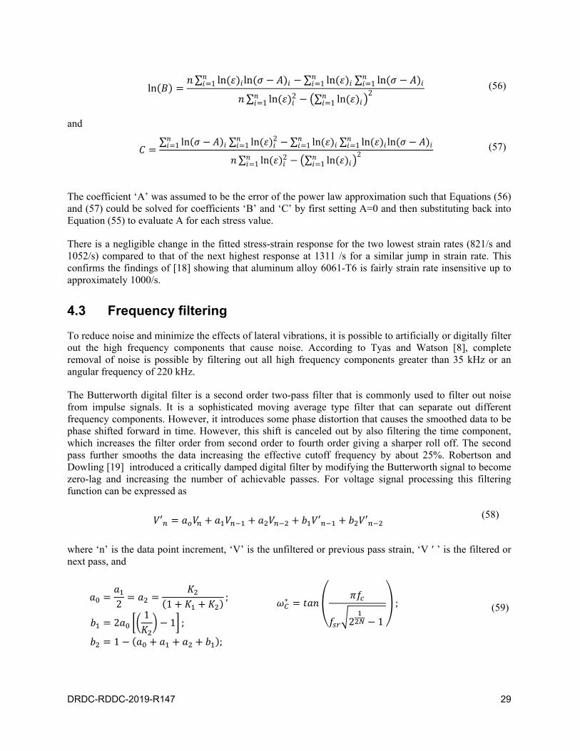
4.3 Frequency filtering
To reduce noise and minimize the effects of lateral vibrations, it is possible to artificially or digitally filter out the high frequency components that cause noise. According to Tyas and Watson [8], complete removal of noise is possible by filtering out all high frequency components greater than 35 kHz or an angular frequency of 220 kHz.
The Butterworth digital filter is a second order two-pass filter that is commonly used to filter out noise from impulse signals. It is a sophisticated moving average type filter that can separate out different frequency components. However, it introduces some phase distortion that causes the smoothed data to be phase shifted forward in time. However, this shift is canceled out by also filtering the time component, which increases the filter order from second order to fourth order giving a sharper roll off. The second pass further smooths the data increasing the effective cutoff frequency by about 25%. Robertson and Dowling [19] introduced a critically damped digital filter by modifying the Butterworth signal to become zero-lag and increasing the number of achievable passes. For voltage signal processing this filtering function can be expressed as
′ ′ ′ (58)
where ‘n’ is the data point increment, ‘V’ is the unfiltered or previous pass strain, ‘V ′ ’ is the filtered or next pass, and
2 1;
21
1 ;
1 ;
∗
2 1
; (59)
ln∑ ln ln1 ∑ ln1 ∑ ln1
∑ ln 21 ∑ ln1
2
∑ ln1 ∑ ln 21 ∑ ln1 ∑ ln ln1
∑ ln 21 ∑ ln1
2

30 DRDC-RDDC-2019-R147
2 ∗ ; ∗ ;
where ‘ωc’ is the incrementally corrected angular cutoff frequency, ‘N’ is the pass number, ‘fc’ is the desired cutoff frequency, and ‘fsr’; is the sampling frequency equal to the total number of data points divided by the total sampling time.
Decreasing the cutoff frequency decreases noise but also increases attenuation and data loss. The results of filtering the voltage signal of Specimen #3 using 50 passes and various cutoff frequencies are shown in Figure 16.
Figure 16: Effect of varying the cutoff frequency on the attenuation of the input bar voltage signal of Specimen #3 using a critically-damped recursive low-pass filter with 50 passes.
The increase in attenuation associated with a decrease in cutoff frequency also results in a slight dampening of the strain rate response of the specimen. For Specimen #3 this dampening effect introduces error in the calculation of average strain rate by a decrease of 3.6% from 1311/s unfiltered to 1264/s at 40 kHz. For the specimens tested, decreasing the cutoff frequency below 40 kHz results in significant data loss. Despite the attenuation of the voltage signal for decreasing cutoff frequencies, there was no significant data loss in the stress-strain responses of the specimes. Low-pass filtering significantly reduced the scattering of data, which fit well with the power-law fitting function derived for the unfiltered data, as shown in Figure 17 for Specimen #3. This indicates that the fitting function provides a good estimation of the data. However, filtering produced an overestimation of the yield point (intercept of dynamic response and elastic curve) observed to be relatively consistent for all selected cutoff frequencies indicating that this point may lie on the moving average of the stress-strain signal around which the data is reduced through filtering. When using low pass filtering techniques it is important to carefully select the cutoff frequency that minimizes data scattering but also minimizes data loss.

DRDC-RD
FigurSpe
4.4 V
The quasiBenck, FiSpecimenFigure 15matched w
Increasingflow strestemperatu
where rate, T* is
DDC-2019-R1
re 17: Effect oecimen #3 sho
Validatio
-static yield silbey, and Ms #1 and #2 t, the average
well with the
g the strain rass model [21ure as,
is the effectis the normaliz
147
of critically-dowing an ove
n of resu
strength of thiMurray [20]. T
tested at or bee stress at 6%stresses at the
ate, increases]—an empiri
ive stress or pzed temperatu
damped filterierestimation o
ults
is alloy underThis yield vaelow the inse
% strain for Se same strain
s the stress reical model th
plastic stress, ure defined as
1
ing on the atteof the yield po
r compressionalue agrees wensitivity straiSpecimens #1according to
esponse of thhat defines fl
is the effe,
01 ∗
enuation of thoint as cut-off
n is approximwell with thein rate of 100
1 and #2 wer[20].
he material. Aflow stress as
fective strain r
he stress-straf frequency is
mately 240 MPe yield streng00/s. Additionre approximat
According to s a function
rate, is the
in response ofdecreased.
Pa as presentgths calculatenally, accorditely 360 MPa
the Johnson-of strain rate
e quasi-static
31
of
ted by ed for ing to a and
-Cooke and
(60)
strain
(61)

32 DRDC-RDDC-2019-R147
and A, B, C, m, and n are coefficients, the strain rate sensitivity parameter ‘C’ for aluminum alloy 6061-T6 has been found to range between 0.002 < C < 0.02 according to [22, 23]. Given a quasistatic strain rate of 0.0001/s, and assuming that all tests are perfomed at room temperature, this sensitivity range would increase the yield strength for a strain rate of 1311/s (Specimen #3) to between 247MPa and 319MPa and for a strain rate of 1730/s (Specimen #4) to between 248MPa to 320MPa. The calculated yield strengths for specimens #3 (275 MPa) and #4 (325 MPa) fall approximately within these ranges validating the analysis to within acceptable error.

DRDC-RDDC-2019-R147 33
5 Conclusion
Spectral wave analysis is a reliable technique that allows for both the filtering and correction of errors induced by vibrations and distortions typically found in elastic Hopkinson bar systems and provides a good approximation to the dynamic response of metallic materials under impact. This report outlined a step-by-step procedure that can be followed to analyze strain gage data and obtain meaningful results necessary in characterizing the impact properties of materials tested in an elastic Hopkinson bar system. The procedure and analysis of aluminum alloy 6061-T6 was found to produce fairly accurate results, validated by the literature.
Spectral wave analysis is also an integral method for analyzing experimental data obtained from viscoelastic Hopkinson pressure bar systems in testing soft materials such as rubbers, soft plastics, and foams where bar distortion effects and dampening is significantly higher than in elastic pressure bar systems. It remains a popular method for predicting strain signals along the bars, correcting for dispersion effects and estimating the average (engineering) dynamic response of soft materials under impact forces, in the absence of advanced measuring techniques such as digital image correlation (DIC), for measuring specimen true strain, and piezoelectric force transducers, for measuring interface forces.
34 DRDC-RDDC-2019-R147
References
[1] H. Kolsky, “An Investigation of Mechanical Properties of Materials at Very High Strain Rates of Loading,” Proc. Phys. Soc. Lon., vol. 62, no. B, pp. 676–700, 1949.
[2] V. P. Group, “Strain Gages and Instruments Tech Note TN-507-1: Errors Due to Wheatstone Bridge Nonlinearity,” 19 November 2010. [Online]. Available: http://www.vishaypg.com/docs/11057/tn5071.pdf. [Accessed December 2017].
[3] M. Bolduc and R. Arsenault, “Improving accuracy in SHPB,” Defence R&D Canada – Valcartier; TR 2005-380, 2008.
[4] M. Kaiser, “Advancements in the Split Hopkinson Bar Test,” Virginia Polytechnic Institute and State University, Blacksburg, Virginia, 1998.
[5] V. P. Group, “Errors Due to Transverse Sensitivity in Strain Gages,” 28 June 2011. [Online]. Available: http://www.vishaypg.com/docs/11059/tn509tn5.pdf. [Accessed 25 April 2018].
[6] P. Follansbee and C. Frantz, “Wave propagation in the split Hopkinson pressure bar,” J. Eng. Mat. Tech, vol. 105, pp. 61–66, 1983.
[7] H. Zhao, G. Gary and J. Klepaczko, “On the use of a viscoelastic split hopkinson pressure bar,” International Journal of Impact Engineering, vol. 19, no. 4, pp. 319–330, 1997.
[8] A. Tyas and A. J. Watson, “An investigation of frequency domain dispersion correction of pressure bar signals,” International Journal of Impact Engineering, vol. 25, pp. 87–101, 2001.
[9] L. Pochhammer, “Über die fortpflanzungsgeschwindigkeiten kleiner schwingungen in einem unbegrenzten isotropen kreiszylinder (On the propagation velocities of small vibrations in an infinite isotropic circular cylinder),” Zeitschrift für Reine und Angewandte Mathematik (Journal for Pure and Appllied Mathematics), vol. 81, pp. 324–336, 1876. (in German).
[10] C. Chree, “The equation of an isotropic elastic solid in polar and cylindrical coordinates, their solution and applicaitons,” Transactions of the Cambridge Philosophical Society, vol. 14, pp. 250–369, 1889.
[11] A. E. H. Love, “A Treatise on the Mathematical Theory of Elasticity Vol. 1, Cambridge: C. J. Clay, M.A. and Sons, at The Univeristy Press, 1934.
[12] D. Bancroft, “The velocity of longitudinal waves in cylindrical bars,” Physical Review, vol. 59, pp. 588–593, 1941.
[13] J. Gong, L. Malvern and D. Jenkins, “Dispersion investigation in the split Hopkinson pressure bar,” J. Eng. Mater. Technol, vol. 112, no. 3, pp. 309–314, 1990.
[14] D. Gorham, “A numerical method for the correction of dispersion in pressure bar signals,” J. Phys. E. Sci.Instrum, vol. 16, no. 6, pp. 477–479, 1983.

DRDC-RDDC-2019-R147 35
[15] D. Gorham and P. F. J. Pope, “An improved method for compressive stress-strain measurements at very high strain-rates,” Proc. Roy. Soc. London A, vol. 438, no. 1902, pp. 153–170, 1992.
[16] Z. Li and J. Lambros, “Determination of the dynamic response of brittle composites by the use of the split Hopkinson pressure bar,” Composites Science and Technology, vol. 59, pp. 1097–1107, 1999.
[17] R. M. Davies, “A critical study of the Hopkinson pressure bar,” Philosopical Transactions of the Royal Society London A, vol. 240, pp. 375–457, 1948.
[18] L. Manes, L. Peroni, M. Scapin and M. Giglio, “Analysis of strain rate behavior of an Al 6061 T6 alloy,” Procedia Engineering, vol. 10, pp. 3477–3482, 2011.
[19] D. Robertson and J. Dowling, “Design and response of Butterowrth and critically damped digital filters,” Journal of Electromyography and Kinesiology, vol. 13, pp. 569–573, 2003.
[20] R. Benck, G. Filbey Jr. and E. Murray Jr., “Quasi-static Compression Stress-Strain Curves – IV, 2024-T3510 and 6061-T6 Aluminum Alloys,” USA Ballistic Research Laboratories, Aberdeen Proving Ground, Maryland, 1976.
[21] G. Johnson and W. Cook, “A constitutive model and data for metals subjected to large strains, high strain rates and high temperatures,” in Proceedings of the Seventh International Symposium on Ballistics, The Hague, The Netherlands, 1983.
[22] B. Corbett, “Numerical simulations of target hole diameters for hypervelocity impacts into elevated and room temperature bumpers,” International Journal of Impact Engineering, vol. 33, pp. 431–440, 2006.
[23] A. Elsen, M. Ludwig, R. Schaefer and P. Groche, "Fundametnals of EMPT-Welding, “in Proceedings of 4th International Conference on High Speed Forming, Columbus, OH, 2010.
[24] S. Rigby and A. Barr, “A review of Pochhammer-Chree dispersion in the Hopkinson bar,” Engineering and Computational Mechanics, pp. 1–16, 2017.

36 DRDC-RDDC-2019-R147
List of symbols/abbreviations/acronyms/initialisms
DND Department of National Defence
DRDC Defence Research and Development Canada
DTFT Discrete-Time Fourier Transform
IDTFT Inverse Discrete-Time Fourier Transform
SHPB Split Hopkinson Pressure Bar
ε Strain
σ Stress
Vexc Bridge excitation voltage
Ag Amplifier gain
GF Gage factor
C0 Fundamental speed of sound in a material
Cω Phase velocity
E Young’s modulus
ν Poisson’s ratio
λ Lame’s first parameter
ρ Density
ω Angular frequency
γ Wave number
Λ Wavelength
Lg Gage length
Jn Bessel function of the first kind, order n
a Bar radius
φ Phase shift

DOCUMENT CONTROL DATA *Security markings for the title, authors, abstract and keywords must be entered when the document is sensitive
1. ORIGINATOR (Name and address of the organization preparing the document. A DRDC Centre sponsoring a contractor's report, or tasking agency, is entered in Section 8.)
DRDC – Valcartier Research CentreDefence Research and Development Canada2459 route de la BravoureQuébec (Québec) G3J 1X5Canada
2a. SECURITY MARKING (Overall security marking of the document including special supplemental markings if applicable.)
CAN UNCLASSIFIED
2b. CONTROLLED GOODS
NON-CONTROLLED GOODS DMC A
3. TITLE (The document title and sub-title as indicated on the title page.)
On spectral wave analysis with distortion corrections applied to elastic Hopkinson bar systems
4. AUTHORS (Last name, followed by initials – ranks, titles, etc., not to be used)
Polyzois, I.
5. DATE OF PUBLICATION (Month and year of publication of document.)
August 2019
6a. NO. OF PAGES (Total pages, including Annexes, excluding DCD, covering and verso pages.)
45
6b. NO. OF REFS (Total references cited.)
24
7. DOCUMENT CATEGORY (e.g., Scientific Report, Contract Report, Scientific Letter.)
Scientific Report
8. SPONSORING CENTRE (The name and address of the department project office or laboratory sponsoring the research and development.)
DRDC – Valcartier Research CentreDefence Research and Development Canada2459 route de la BravoureQuébec (Québec) G3J 1X5Canada
9a. PROJECT OR GRANT NO. (If appropriate, the applicable research and development project or grant number under which the document was written. Please specify whether project or grant.)
02ba - Véhicules opérationnels
9b. CONTRACT NO. (If appropriate, the applicable number under which the document was written.)
10a. DRDC PUBLICATION NUMBER (The official document number by which the document is identified by the originating activity. This number must be unique to this document.)
DRDC-RDDC-2019-R147
10b. OTHER DOCUMENT NO(s). (Any other numbers which may be assigned this document either by the originator or by the sponsor.)
11a. FUTURE DISTRIBUTION WITHIN CANADA (Approval for further dissemination of the document. Security classification must also be considered.)
Public release
11b. FUTURE DISTRIBUTION OUTSIDE CANADA (Approval for further dissemination of the document. Security classification must also be considered.)
12. KEYWORDS, DESCRIPTORS or IDENTIFIERS (Use semi-colon as a delimiter.)
Spectral wave analysis; Hopkinson pressure bar; Impact Dynamics; Material Characterisation;aluminum 6061-T6
13. ABSTRACT (When available in the document, the French version of the abstract must be included here.)

The dynamic mechanical properties of materials used in defense applications, under high strain rate and shock loading, are necessary in designing and optimizing their capabilities under such conditions. The split Hopkinson pressure bar (SHPB) technique has been a popular test method for characterizing the properties of materials under dynamic loading at moderate to high strain rates by predicting the propagation of pressure waves in long slender bars. This paper outlines the procedure for predicting the propagation of pressure waves in an elastic split Hopkinson bar system and correcting for dispersion and radial inertia effects. The procedure is then used to characterize the high strain rate properties of aluminum alloy 6061-T6 under impact and validated against the literature.
Pour concevoir des matériaux employés aux fins d’applications de défense impliquant des vitesses de déformation élevées et de puissants chocs de chargement, ainsi que pour optimiser les capacités de ces matériaux dans telles conditions, il est important de tenir compte de leurs propriétés mécaniques dynamiques. La technique de la barre de pression Hopkinson (Split Hopkinson Pressure Bar – SHPB) constitue une méthode répandue de caractérisation des propriétés de matériaux soumis à des charges dynamiques impliquant des vitesses de déformation moyennes à élevées, grâce à la prévision de la propagation d’ondes de pression dans de longues barres effilées. Le présent article donne un aperçu d’une procédure suivie pour prévoir la propagation d’ondes de pression dans un système élastique de barre Hopkinson, de même que pour corriger des effets de dispersion et d’inertie radiale. La procédure sert ensuite à caractériser les propriétés de vitesse de déformation élevée de l’alliage d’aluminium 6061-T6 lorsqu’il subit des impacts, ainsi qu’à valider ces propriétés en fonction de ce qui figure dans d’autres articles.


![MagneticElectricAcousticSignatureUnderwater ... · DRDC-RDDC-2019-D140 1 1 Introduction InsupportoftheMaritimeEvaluation(EvaluationofNavalSignatureManagementSystem[1]),thethird](https://img.dokumen.tips/doc/110x75/60a29e262972c90ec51a9934/magneticelectricacousticsignatureunderwater-drdc-rddc-2019-d140-1-1-introduction.jpg)