Embed Size (px)
Citation preview


Lesson 1 TYPES OF FLOORS AND THEIR STRUCTURAL ARRANGEMENT
Lesson 2 SCREEDS – TYPES AND PROPERTIES
Lesson 3 CEMENT SCREEDS
Lesson 4 ANHYDRITE SCREEDS
Lesson 5 WORKS ACCEPTANCE & COMMON MISTAKES

1
SCHOOL OF FLOORING
SCHOOLLESSON
1
OF FLOORING
We start with a short revision of the basic information regarding fl oors in the buildings. Let's begin with defi n-ing the essential terms which will appear in the subse-
quent articles of this series. ◆ The fl oor is a horizontal element of a building, which forms
the upper part of a ceiling, a foundation or the ground. It consists of several layers which fulfi ll various functions within the system. Floors provide resistance related to the transfer of operational loads, assure thermal, acoustic and damp-proof insulation up to the given require-ments and standards, ensure decorative and functional properties.
◆ The fl oor fi nish is one of the layers of the fl oor on which one can walk, drive vehicles, set the furniture, etc. It is an outer, func-tional and decorative layer. The fl oor fi nish can be represented then by any fl oor coverings: ceramic tiles, wooden and wood-based materials (fl oor panels, wooden boards or parquet), carpets, PVC, epoxy materials, etc. The fl oor fi nish can also be made of the layer of concrete or cement mortar applied directly onto the ground. This solution is particularly used in the utility rooms.
◆ The fl oor fi nish is applied on the screed (subfl oor) - a layer which is placed between the substrate (ceiling or foundation) and the fl oor fi nish. The main objective of a screed is to elevate the fl oor level in a room and to provide an appropriate surface profi le (slope or horizontal) and evenness enabling the application of a fl oor fi nish.
TYPES OF FLOORSThe most general division of fl oors is a division into multi-layer fl oors (Fig. 1) and single-layer fl oors (Fig. 2).
◆ A single-layer fl oor is a type of a fl oor which is formed of a single layer of material only, e.g. concrete or cement fl oor fi nish, applied directly onto the substrate. This layer provides the appropri-ate plane and forms the outer, functional fi nish.
Following the “School of Insulation” and the “School of Tiling” brochures we continue our lessons on the ATLAS technology. This time we are going to take a closer look at the fl ooring. This brochure includes both the information concerning theoretical issues, which helps to organise one’s knowledge about the fl oors and appropriate selection of their individual layers, as well as the practical advices on the technology of the fl ooring works.
◆ A multi-layer fl oor is a complex structure, in which the fl oor is composed of several, consecutively applied layers of different materials. The fl oor is executed on the structural substrate - it may be the ceiling of the building or alternatively the ground. The fi rst fl oor layer levels the substrate unevenness and initially forms the fl oor level, alternatively the slight slope (e.g. in wet compart-ments). Usually this layer is made of concrete or ferroconcrete slab.
Fig. 1 Multi-layer � oor – structural arrangement
substrate
fl oor
fl oor fi nish -ceramic tiles, adhesive
screed (subfl oor)
protective layer
thermal/acoustic insulation
vapour barrier
load-bearing structure- fl oor slab

2
SCHOOL OF FLOORING
The next layer is the damp proofi ng (in case of fl oor installed on the ground) or the vapour barrier (in case of inter-storey slab fl oor) and a layer of the thermal/acoustic insulation applied sub-sequently. In order to protect the insulating layer against the ab-sorption of technological water from the subsequent screed layer, it is necessary to apply a protective layer (e.g. made of the construction PE foil 0.2 mm). The previously mentioned screed is the next layer. It can be made of materials based on cement or anhydrite (in dry compartments). With the application of the screed one obtains the fl oor level close to the required one. As the screed also works as the substrate for the fl oor fi nish, it must be suffi ciently even. If the required evenness is not reached, one must apply an additional thin layer – it’s the smoothing layer.
STRUCTURAL ARRANGEMENTS OF FLOORSA second division of fl oors can be made in respect of their possible structural arrangement. We can distinguish bonded fl oors, fl oors on separation layer and fl oating fl oors.
◆ Screed bonded to the substrate (bonded fl oor) is an ar-rangement in which the layer of the fresh material is bonded to the existing substrate (ceiling, layer of concrete) on its entire sur-face. The minimum thickness of the bonded fl oor relates to the type of material in use, therefore it must always be considered during the materials selection. The exemplary solution of this type of arrangement is shown in Fig. 3, where the 20 mm thick layer of the fast-drying cement screed ATLAS POSTAR 20 is used.
◆ Floor on the separation layer is executed on the interlayer which separates the fresh screed layer from the existing substrate on its entire surface. The separation layer can be made of damp proofi ng or, e.g. of the PE polyethylene foil of minimum thickness of 0.2 mm. This arrangement is often used in case of renovations, when the existing substrate is not strong enough for the new fl oor layer installation, too weak or permanently contaminated with, e.g. adhesive for PVC tiles, etc. Since the layer is not permanently bonded to the building structural elements, it must form a self-supporting slab which enables normal rooms operation. The recommended minimum thickness of the screed layer in this structural arrangement equals 35 mm. The exemplary solution of this type of arrangement is shown in Fig. 4, where the 35 mm thick layer of ATLAS POSTAR 40 is executed on the separation layer made of the PE polyethylene foil.
Fig. 2 Single-layer � oor – structural arrangement Fig. 3 Screed/ sub� oor bonded to the substrate – structural arrangement
Fig. 4 Screed on the separation layer – structural arrangement
substrate
fl oorfl oor fi nish – cement mortar
load-bearing structure
ground
substrate
fl oor ATLAS POSTAR 20 - 20 mm
load-bearing structure – fl oor slab
substrate
fl oorATLAS POSTAR 40 – 35 mm
0.2 mm thick PE foil
load-bearing structure – fl oor slab

3
SCHOOL OF FLOORING
◆ Floating screed is executed on a layer of thermal insulation and/or acoustic insulation laid on the substrate. It is worth bearing in mind that in relation to the building partitions, such as ceilings and fl oors on the ground, one should apply, beside the construc-tion requirements related to the safe operation, the requirements related to the thermal insulation and the acoustic insulation (it is particularly important in case of multi-family buildings). These requirements are listed in the respective documents issued by an appropriate body of any European Union country. In order to meet these requirements (Tab. 1), it is necessary to use the thermal insulation in the form of EPS boards, XPS boards or spe-cial hardened mineral wool panels. Only the materials specially designed for fl oors must be used for this purpose. One must not use, e.g. the façade polystyrene, because the layer of the fl oor thermal insulation must keep the required compressibility. The thickness of the insulation layer should result from the calcu-lation and current regulations (Tab. 1). One applies the protective layer (0.2 mm thick polyethylene foil) on the laid thermal/acoustic insulation and then executes the screed layer. The layer of the fl oating screed works as a pressure slab and a stiffening layer beneath the fl oor fi nish. The minimum thickness of the fl oating screed is 40 mm. The exemplary solution of this type of arrange-ment is shown in Fig. 5. We recommend using a 40 mm thick layer of ATLAS POSTAR 100 – a self-spreading cement fl oor.
Fig. 5 Floating screed – structural arrangement A special type of the fl oating fl oor arrangement is the one with the underfl oor heating. It is a structural arrangement in which the elements of the heating system are installed in the screed layer. Heating can be provided with water or electricity. There-fore, the heating elements are the heating pipes or the heating cables, respectively. They can be placed in the fl oor layer either by the application on the thermal insulation layer or within the screed layer (with covering). In order to maximize the perfor-mance of the heating system, it is required to apply the ther-mal insulation which prevents heat loss to the outside. Figure 6 shows an exemplary arrangement of the fl oating screed with the water underfl oor heating. Heating pipes are placed in the 60 mm thick layer of the self-leveling screed ATLAS SAM 150. The mini-mum 35 mm layer thickness above the heating elements is kept.
◆ Floor on the ground. In the modern construction, the buildings usually do not have basements. Therefore, the fl oor on the ground is at the same time the fl oor of the residential compartments. The appropriate arrangement of the layers is shown in Fig. 7. The hard core layer of the compacted sand is applied onto the ground. Its main objective is to level the surface and to enable the application of the consecutive layers of the same thickness within the entire fl oor surface. The next layer is the fi ltrating layer made of break-stone. Its task is to break the capillary rising of the groundwater to the fl oor layers. Then one applies the protective layer – made of the geotextile or the dimpled membrane. The hard core, the fi ltrating layer and the geotextile form the foundation onto which one executes the subsequent fl oor layers. The fi rst of them is the concrete or ferroconcrete slab, which forms the load bearing layer.
Type of partition and tempera-ture in a compartment
Overall heat transfer coeffi cient U(max)
I 2014 I 2017 I 2021*
� oor on the groundat ti > 16°Cat 8° C < ti ≤ 16°Cat ti < 8°C
0.31.21.5
0.31.21.5
0.31.21.5
slab roofs and ceilings under unheated attics or over passagesat ti > 16°Cat 8°C < ti ≤ 16°Cat ti < 8°C
0.20.30.7
0.180.30.7
0.150.30.7
ceilings above unheated compart-ments and encased under� oor zonesat ti > 16°Cat 8°C < ti ≤ 16°Cat ti < 8°C
0.250.31.0
0.250.31.0
0.250.31.0
ceilings above heated underground compartments and inter-storey ceilingsat ti > 16°Cat 8°C < ti ≤ 16°Cat ti < 8°C
1.0no requir-
ments0.25
1.0no requir-
ments0.25
1.0no requir-
ments0.25
ti – temperature of heated compartment
*Public access buildings from I 2019
fl oor fi nish – ceramic tilesATLAS PLUS
ATLAS POSTAR 100 – 40 mm0.2 mm thick PE foil
EPS T boards – 50 mm
0.2 mm thick PE foil
load-bearing structure – fl oor slab
substrate
fl oor
Tab. 1 Requirements for the thermal insulation for all types of buildings (for Poland, check your local regulations)

4
SCHOOL OF FLOORING
Fig. 6 Floating screed with the under� oor heating – structural arrangement
Fig. 7 Floor on the ground – appropriate arrangement of layers.
Fig. 8 Floor on the wooden slab – appropriate arrangement of layers.
1. Genuine ground 2. Leveling base of sand 3. Filtrating layer of breakstone 4. Geotextile or dimpled membrane 5. Concrete or ferroconcrete slab 6. IZOHAN IZOBUD WL primer (diluted with water in 1:1 ratio) + IZOHAN IZOBUD WM damp proofi ng 7. Thermal or acoustic insulation 8. PE foil 9. ATLAS POSTAR 80 cement screed10. Parquet applied onto the screed
1. Wooden slab2. Thermal or acoustic insulation3. PE foil4. ATLAS POSTAR 80 cement screed5. ATLAS WODER E/ AVAL KL 51 under-tile damp proofi ng6. ATLAS PLUS EXPRESS adhesive7. Gres-porcelain and other ceramic large-size tiles8. ATLAS ARTIS grout
Next, the damp proofi ng is applied. It can be made of the IZOHAN IZOBUD WM asphalt-rubber mass which protects the compart-ment from the groundwater. Having completed the damp proof-ing, one can execute the thermal insulation layer – made of XPS, hard EPS boards or alternatively of special mineral wool panels and then proceed to the application of the fl oating fl oor, made of, e.g. ATLAS POSTAR 80 (as described earlier).
◆ Floor on the wooden slab. This solution is mainly used in the renovated buildings. The specifi city of the construction of this fl oor type results from the structure working conditions and the type of the construction materials which are usually the wooden or the wood-based boards (e.g. OSB). Therefore, one does not execute the screed bonded to the substrate there. The appropriate arrange-ment of layers is shown in Fig. 8, where the fl oor with ceramic tiles top fi nish is executed in a wet compartment. The 40 mm layer of ATLAS POSTAR 80 screed is applied onto the thermal/acoustic insu-lation protected with the 0.2 mm thick PE foil.
substrate
fl oor
fl oor fi nish – ceramic tilesATLAS PLUS
0.2 mm thick PE foil
EPS T boards – 50 mm
0.2 mm thick PE foil
load-bearing structure – fl oor slab
5
SCHOOL OF FLOORING
SCHOOLLESSON
2
OF FLOORING
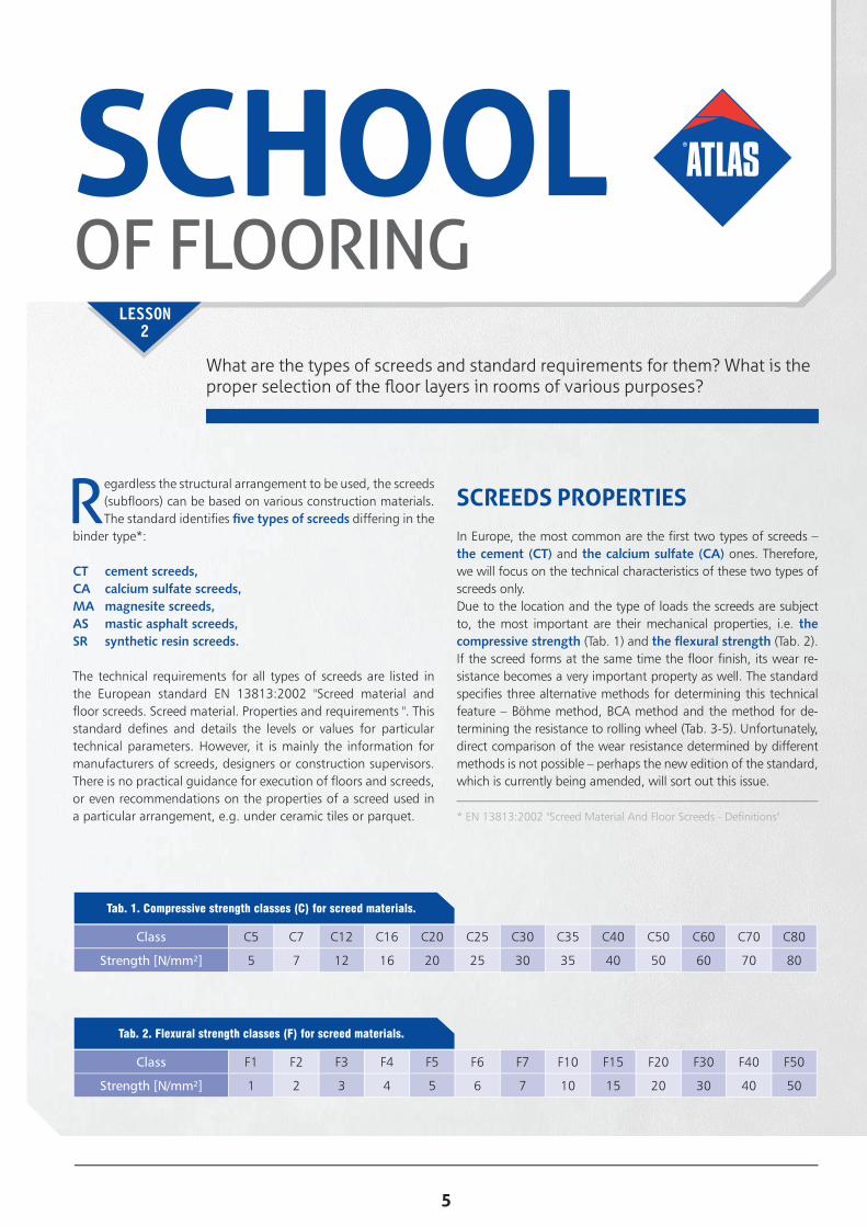
Regardless the structural arrangement to be used, the screeds (subfl oors) can be based on various construction materials. The standard identifi es fi ve types of screeds differing in the
binder type*:
CT cement screeds,CA calcium sulfate screeds,MA magnesite screeds,AS mastic asphalt screeds,SR synthetic resin screeds.
The technical requirements for all types of screeds are listed in the European standard EN 13813:2002 "Screed material and fl oor screeds. Screed material. Properties and requirements ". This standard defi nes and details the levels or values for particular technical parameters. However, it is mainly the information for manufacturers of screeds, designers or construction supervisors. There is no practical guidance for execution of fl oors and screeds, or even recommendations on the properties of a screed used in a particular arrangement, e.g. under ceramic tiles or parquet.
What are the types of screeds and standard requirements for them? What is the proper selection of the fl oor layers in rooms of various purposes?
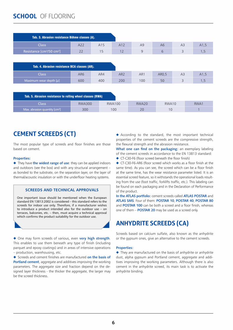
SCREEDS PROPERTIESIn Europe, the most common are the fi rst two types of screeds – the cement (CT) and the calcium sulfate (CA) ones. Therefore, we will focus on the technical characteristics of these two types of screeds only. Due to the location and the type of loads the screeds are subject to, the most important are their mechanical properties, i.e. the compressive strength (Tab. 1) and the fl exural strength (Tab. 2). If the screed forms at the same time the fl oor fi nish, its wear re-sistance becomes a very important property as well. The standard specifi es three alternative methods for determining this technical feature – Böhme method, BCA method and the method for de-termining the resistance to rolling wheel (Tab. 3-5). Unfortunately, direct comparison of the wear resistance determined by different methods is not possible – perhaps the new edition of the standard, which is currently being amended, will sort out this issue.
* EN 13813:2002 "Screed Material And Floor Screeds - Defi nitions"
Class C5 C7 C12 C16 C20 C25 C30 C35 C40 C50 C60 C70 C80
Strength [N/mm²] 5 7 12 16 20 25 30 35 40 50 60 70 80
Tab. 1. Compressive strength classes (C) for screed materials.
Class F1 F2 F3 F4 F5 F6 F7 F10 F15 F20 F30 F40 F50
Strength [N/mm²] 1 2 3 4 5 6 7 10 15 20 30 40 50
Tab. 2. Flexural strength classes (F) for screed materials.
6
SCHOOL OF FLOORING
CEMENT SCREEDS (CT)The most popular type of screeds and fl oor fi nishes are those based on cement.
Properties: ◆ They have the widest range of use: they can be applied indoors
and outdoors (see the box) and with any structural arrangement – as bonded to the substrate, on the separation layer, on the layer of thermal/acoustic insulation or with the underfl oor heating systems.
◆ One may form screeds of various, even very high strength. This enables to use them beneath any type of fi nish (including parquet and epoxy coatings) and in areas of intensive operations – production, warehousing, etc.
◆ Screeds and cement fi nishes are manufactured on the basis of Portland cement, aggregate and additives improving the working parameters. The aggregate size and fraction depend on the de-signed layer thickness - the thicker the aggregate, the larger may be the screed thickness.
◆ According to the standard, the most important technical properties of the cement screeds are the compressive strength, the fl exural strength and the abrasion resistance.What one can fi nd on the packaging: an exemplary labeling of the cement screeds in accordance to the EN 13813 standard:
◆ CT-C30-F6 (fl oor screed beneath the fl oor fi nish) ◆ CT-C30-F6-AR6 (fl oor screed which works as a fl oor fi nish at the
same time). As you can see, the screed which can be a fl oor fi nish at the same time, has the wear resistance parameter listed. It is an essential screed feature, so it withstands the operational loads result-ing from the use (foot traffi c, forklifts traffi c, etc.). This labeling can be found on each packaging and in the Declaration of Performance of the product.In the ATLAS portfolio: cement screeds called ATLAS POSTAR and ATLAS SMS. Four of them: POSTAR 10, POSTAR 40, POSTAR 80 and POSTAR 100 can be both a screed and a fl oor fi nish, whereas one of them – POSTAR 20 may be used as a screed only.
ANHYDRITE SCREEDS (CA)Screeds based on calcium sulfate, also known as the anhydrite or the gypsum ones, give an alternative to the cement screeds.
Properties: ◆ They are manufactured on the basis of anhydrite or anhydrite
dust, alpha gypsum and Portland cement, aggregate and addi-tives improving the working parameters. Although there is also cement in the anhydrite screed, its main task is to activate the anhydrite binding.
Class A22 A15 A12 A9 A6 A3 A1,5
Resistance [cm³/50 cm²] 22 15 12 9 6 3 1,5
Tab. 3. Abrasion resistance Böhme classes (A).
Class AR6 AR4 AR2 AR1 AR0,5 A3 A1,5
Maximum wear depth [µ] 600 400 200 100 50 3 1,5
Tab. 4. Abrasion resistance BCA classes (AR).
Class RWA300 RWA100 RWA20 RWA10 RWA1
Max. abrasion quantity [cm³] 300 100 20 10 1
Tab. 5. Abrasion resistance to rolling wheel classes (RWA)
SCREEDS AND TECHNICAL APPROVALS
One important issue should be mentioned when the European standard EN 13813:2002 is considered – this standard refers to the screeds for indoor use only. Therefore, if a manufacturer wishes to introduce a product intended also for the outdoor use – on terraces, balconies, etc. – then, must acquire a technical approval which confi rms the product suitability for the outdoor use.

7
SCHOOL OF FLOORING
◆ No shrinkage during binding – this allows to pour large areas without the need for additional intermediate expansion joints. For example, if one uses ATLAS SAM 150 screed, there is no need for expansion joints on the areas up to 50 m2, providing that the diagonal of the compartment is not longer than 10 meters. This simplifi es the execution and is important for investor, as the lack of expansion joints eliminates the need for transferring them onto the top fi nish layer.
◆ Due to the low linear shrinkage of the binding anhydrite, the layer does not provide concavities or convexities. Therefore, no scratches and cracks occur during binding, which is often an issue in case of the cement mortars.
◆ The screeds based on calcium sulfate are designed for the ma-chine application. The liquid consistency of the mass enables easy spreading and leveling the screed plane. This property, supported by the aggregate fi ner than in the cement screeds, provides more accurate tucking of the cables or the heating pipes. It virtually elimi-nates the possibility of leaving voids, which can reduce the effi ciency of the heating system, around the cables – the substrate is more homogenous within its whole thickness.
◆ Another advantage of the anhydrite screeds in regard to
ATLAS POSTAR 20Floor screed used beneath the ceramic and the stone tiles, PVC and carpet fl ooring*, fl oor panels – recommended for any type of the surface subject to medium and large loads.
Main properties: further works just after
5 days, foot traffi c after 24 hours, limited linear shrinkage, for places exposed to
permanent damp.
Main parameters: consumption: 20 kg/1 m2/1 cm layer thickness: 10-80 mm compressive strength:
≥ 20 N/mm2
**Before the application one should execute a smoothing layer with the use of ATLAS SMS 15 or ATLAS SMS 30.
ATLAS POSTAR 10It may be used as the fl oor fi nish or screed beneath the top fi nishes like: ceramic and stone tiles, epoxy fl oors and coatings, PVC and carpet fl oorings, parquet and fl oor panels.
Main properties: for places exposed to
permanent damp, high cohesion, low linear shrinkage, for underfl oor heating, bonded, on separation layer
or fl oating.
Main parameters: consumption:
20 kg/1 m2/1 cm layer thickness: 10-100 mm compressive strength:
≥ 25 N/mm2
ATLAS POSTAR 80It is recommended for quick repairs. It may be used as the fl oor fi nish or screed beneath the top fi nishes like: ceramic and stone tiles, epoxy fl oors and coatings, PVC and carpet fl oorings*, parquet and fl oor panels.
Main properties: further works just after 24
hours, foot traffi c after 3 hours, limited linear shrinkage, high cohesion, thick plasticity.
Main parameters: consumption: 20 kg/1 m2/1 cm layer thickness: 10-80 mm high compressive strength:
≥ 40 N/mm
*Before the application one should execute a smoothing layer with the use of ATLAS SMS 15 or ATLAS SMS 30.
ATLAS POSTAR 40It forms fl oor fi nish layer of high wear resistance – recommended for residential buildings, warehouses, production halls, driveways, terraces, etc. It may be used as the fl oor fi nish or screed beneath the top fi nishes like: ceramic and stone tiles, epoxy fl oors and coatings, PVC and carpet fl oorings, parquet and fl oor panels.
Main properties: for places exposed to
permanent damp, high cohesion, low linear shrinkage, for underfl oor heating, bonded, on separation layer
or fl oating.
Main parameters: consumption: 20 kg/1 m2/1 cm layer thickness: 10-80 mm compressive strength:
≥ 30 N/mm2
high compressive strength: ≥ 30 N/mm2
ATLAS POSTAR 100It forms the fl oor fi nish layer of high strength – it is used on loading ramps, driveways, underground garages, parking lots, terraces, balconies, warehouses, production halls, etc. It may be used as the fl oor fi nish or screed beneath the top fi nishes like: ceramic and stone tiles, epoxy fl oors and coatings, PVC and carpet fl oorings, parquet and fl oor panels.
Main properties: limited linear shrinkage, easy application, applied manually or
mechanically.
Main parameters: consumption: 20 kg/1 m2/1 cm layer thickness: 10-80 mm high compressive strength:
≥ 50 N/mm2
CEMENT PRODUCTS – ATLAS POSTAR 10, 20, 40, 80, 100
the execution of an underfl oor heating is their high thermal conductivity coeffi cient, much higher than in case of the cement screeds. The anhydrite screed with the heating system heats up quicker and provides more effi cient compartment heating.
◆ Restrictions for using the anhydrite products: one should re-member that they can be used only indoors and only in dry rooms. Moreover, the anhydrite screed requires longer ageing before the execution of the fl oor fi nish. The moisture of the screed/ subfl oor should not exceed 1.5%, whereas in case of the cement screeds fur-ther works can commence with the 3% humidity.
What is on the packaging: an exemplary labeling of the calcium sulfate screed in accordance to the EN 13813 standard: CA-C20-F5. This labeling can be found both on the product packaging and in the Declaration of Performance.
In ATLAS portfolio: anhydrite screeds called ATLAS SAM. Three of them: SAM 150, SAM 200 (AVAL KN 20) and SAM 500 can be used in any possible structural fl oor arrangement. Two others: SAM 55 and SAM 100 (AVAL KN 10) are used mainly to improve the quality and to level the existing screeds.

8
SCHOOL OF FLOORING
CRITERIA FOR SELECTING THE FLOOR FINISHES AND SCREEDSThe screed and especially the fl oor top fi nish must be designed and installed with consideration of its location and the type of load resulting from operation. The choice of material, thickness and structural arrangement should be made taking into account the required strength parameters, thermal and acoustic issues and conditions under which the material will be used. The basic issues related to the choice of the materials can be classifi ed into one of the following groups:
◆ Place of application (indoors, outdoors). Type of room (dry, wet). The location of the fl oor fi nish or the screed is the basic criteria for the suitable material selection. Outdoors, one may use the cement materials only. This is due to the fact that products based on calcium sulfate are not resistant to moisture. Thus, they can-not be used neither outdoors nor in the wet compartments. Nev-ertheless, one should check whether a particular cement screed can be used outdoors.
◆ Purpose of a room (residential, production, warehouse).Purpose of a room can determine the type and standard of the
ANHYDRITE PRODUCTS – ATLAS SAM 55, 100, 150, 200, 500
ATLAS SAM 100It is recommended for leveling the screeds in dry compartments: rooms, antechambers, halls, living rooms, offi ces, corridors, waiting rooms etc. It forms a screed beneath the tiles, PVC and carpet fl oorings, fl oor panels.
Main properties: anhydrite-gypsum, resistant to concentrated
load, no need of expansion joints
for up to 50m2, bonded to the substrate.
Main parameters: consumption:
20 kg/1 m2/10 mm layer thickness: 5-30 mm compressive strength:
≥ 35 N/mm2
ATLAS SAM 55Forms a screed beneath the tiles, PVC and carpet fl oorings, fl oor panels in the compartments subject to medium loads – residential buildings, offi ces, kindergartens, schools.
Main properties: anhydrite-gypsum, resistant to concentrated
load, no need of expansion joints
for up to 50m2, wide-spread and fast-
setting,bonded to the substrate.
Main parameters: consumption:
18 kg/1 m2/10 mm layer thickness: 1-10 mm compressive strength:
≥ 30 N/mm2
ATLAS SAM 200It levels the substrates in dry compartments: rooms, antechambers, halls, living rooms, offi ces, corridors, waiting rooms etc. Product works perfectly as a layer for embedding the electric or the water underfl oor heating. It forms a screed beneath the tiles, PVC and carpet fl oorings, fl oor panels.
Main properties: anhydrite-gypsum, no need of expansion joints
for up to 50m2, consistency can be
regulated, conducts heat very well, self-leveling – facilitates
application.
Main parameters: consumption:
20 kg/1 m2/10 mm layer thickness: 25-60 mm compressive strength:
≥ 16 N/mm2
ATLAS SAM 150Product works perfectly as a layer for embedding the electric or the water underfl oor heating. It can be used in dry compartments: rooms, antechambers, halls, living rooms, offi ces, corridors, waiting rooms etc. It forms a screed beneath the tiles, PVC and carpet fl oorings, fl oor panels.
Main properties: anhydrite-gypsum, foot traffi c already after
6 hours, no need of expansion joints
for up to 50m2, conducts heat well, self-leveling – facilitates
application.
Main parameters: consumption:
20 kg/1 m2/10 mm layer thickness: 15-60 mm, compressive strength:
≥ 20 N/mm2
ATLAS SAM 500It levels the substrates in dry compartments: rooms, antechambers, halls, living rooms, offi ces, corridors, waiting rooms etc. Product works perfectly as a layer for embedding the electric or the water underfl oor heating. It forms a screed beneath the tiles, PVC and carpet fl oorings, fl oor panels.
Main properties: anhydrite-gypsum, no need of expansion joints
for up to 50m2, fast-setting – foot traffi c
just after 6 hours conducts heat very well, self-leveling – facilitates
application.
Main parameters: consumption:
18 kg/1 m2/10 mm layer thickness: 20-60 mm compressive strength:
≥ 20 N/mm2
fl oor fi nish. The cement screed often forms the fi nishing layer in the utility and auxiliary rooms.
◆ Structural arrangement (bonded, on the separation layer, fl oating, heating).The structural arrangement is an important issue, as depending on the adopted arrangement one must use the corresponding recommended layer thickness (you can fi nd more information concerning this issue in the previous lesson of this brochure).
◆ Type of the fl oor top fi nish (tiles, fl oor panels and boards, parquet, epoxy materials, etc.).The type of the fl oor fi nish – the functional layer of the fl oor – it is important, because it enables to determine the technical parame-ters for the substrate. For example, there are different parameters for the fl oor panels, parquet and epoxy materials.
◆ Operational factors.Operational factors relate to the conditions under which the ma-terial will be used. In the utility rooms and the industrial build-ings one should consider higher requirements in this regard – e.g. higher chemical resistance, wear (abrasion) resistance, etc. These guidelines do not release from the obligation to comply with the existing specifi cations and design documentation for a particular project.

9
SCHOOL OF FLOORING
LESSON3
SUBSTRATE PREPARATION
The method of the substrate preparation depends on the structural arrangement to be executed. At the beginning, here are some basic rules:
◆ One should pay great attention when preparing the substrate, especially in case of bonded fl oors.
◆ The substrate should be dry and aged – it is advisable to stabi-lize the cement substrates for 28 days and the concrete substrates for approx. 3 months.
◆ The moisture content of the substrate before application of the subsequent layers – it should not exceed 3%.
◆ The substrate must be strong enough – one should remember about the principle of applying a weaker layer onto a stronger one. In addition, it should be sound enough (this applies to wooden ceilings and OSB boards).
◆ One should also clean the substrate from any layers which can deteriorate the adhesion and from weak and loosening elements. How to check where to execute local fi llings in the loosening spots? It is notifi ed by thuds while tapping.
◆ In order to fi ll any individual substrate points, it is recommended to use the material which is easy to mould and quick binding, e.g. ATLAS ZW330 leveling mortar. Scratches or cracks in the sub-strate must be repaired depending on the situation.
◆ Proper priming is crucial. In case of absorbent substrates, it is recommended to use an emulsion which will reduce the absorp-tion – ATLAS UNI-GRUNT PLUS (AVAL KN 97). Optionally, one can use ATLAS Uni-Grunt (AVAL KT 17) diluted with water in 1:1 ratio (Photo 1)
In the third part of our brochure we are going to focus on the technology of installation of the cement screeds. This lesson lists the core principles on the substrate preparation and the brief instructions on the screeds manual or machine application.
◆ In case of traditionally-applied mortars, for example ATLAS POSTAR, it is advisable to execute a contact (bonding) layer of the cement slurry. This can be done with the ATLAS ADHERmortar or with the mixture of the material to be used and ATLAS ELASTIC EMULSION. One should commence the application of the fl ooring layer before the contact layer dries – with the "wet on wet" method.
◆ In case of the arrangement on the separation layer, one can assume that the parameters and properties of the substrate are not of such great importance in view of adhesion, as both layers
Photo 1. Priming with the use of ATLAS Uni-Grunt (AVAL KT 17) emulsion
SCHOOLOF FLOORING

10
SCHOOL OF FLOORING
are separated over the entire surface. Then, as a separating layer one can use, e.g. 0.2 mm thick PE membrane, spread without rucks on the substrate free of any projecting elements. The adja-cent strips of the membrane should overlap with approx. 30 cm. Additionally, one can tape the joints with a waterproof tape. The membrane should be curled up onto the walls above the designed level of the executed layer.
◆ When executing the fl oating screed, i.e. on the layer of ther-mal or acoustic insulation, one should ensure that the boards are laid on the even substrate and they do not move when pressed. Before laying the boards on the substrate, one can apply a base of dry sand which, properly distributed and compacted, elimi-nates any local unevenness. The insulation boards are placed in one or two layers with the offset of the edges. Afterwards, one lays the protective layer onto them (analogously to the previous description).
◆ If we arrange the layers with the water heating system, then the heating installation should be properly distributed and securely mounted to the substrate. Prior to the execution of the screed the tightness test needs to be performed. Note that the heating pipes should be fi lled with water during works.
Photo 2. The intermediate expansion joints determine the tech-nological areas in the shape of a square or similar.
EXPANSION JOINTS ◆ The proper execution of the expansion joints is crucial when
installing the cement fl oor fi nish or the screed. It results from the properties of the cement-based products which shrink during binding – this phenomenon may cause cracking or loosening off the substrate.
◆ First of all one should execute (repeat) the structural expansion joints - they must go through all the layers of the fl oor.
◆ One can also distinguish the intermediate expansion joints (anti-shrinking, zonal). Their task is to divide the surface into smaller technological areas (Photo 2). Their distribution should be designed in the way to determine the areas similar in shape to a square. If it is diffi cult to be done, one should plan the techno-logical areas so as the ratio between the area sides is not larger than 2:1. The expansion joints should be also implemented at points where the shape of a room changes - at thresholds and along the joints between different construction materials.
◆ The third type of the expansion joints are the perimeter ex-pansion joints (peripheral, insulating). Their task consists in the permanent separation of the layer from the vertical elements of the building – walls, columns, stairs, etc. It is recommended to use ATLAS self-adhesive expansion joint profi les or narrow, approx. 10 mm thick, polystyrene strips.
SMS 30Manufactured in the form of a dry
mix based on Portland cement, quartz fi llers and modifying
additives. For use beneath the tiles, carpet fl oorings, fl oor panels, parquet. Thickness 3-30 mm. Foot
traffi c after 4h.
SMS 15 Manufactured in the form of a
dry mix based on cement. For use beneath the tiles, carpet fl oorings,
fl oor panels, parquet. Thickness 1-15 mm. Foot traffi c after 4h.
11
SCHOOL OF FLOORING
be joined before the bonding process starts, i.e. within 30-40 minutes.
STEP 1. Prepare the mortar by mixing the dry mix with the indi-cated volume of water using a low-speed mixer with a paddle for mortars. It is recommended to perform a test in order to control the obtained consistency. The test consists in pouring the mortar from a 1-liter-jug onto an even, non-absorbent surface (e.g. co-vered with a foil). The formed "patch" should have a diameter of approx. 45-50 cm (check the manufacturer’s recommendations).
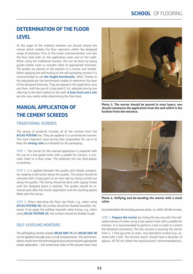
Photo 3. The mortar should be poured in even layers; one should commence the application from the wall which is the furthest from the entrance.
Photo 4. Unifying and de-aerating the mortar with a mesh roller.
DETERMINATION OF THE FLOOR LEVELAt the stage of the material selection we should choose the mortar which enables the fl oor execution within the designed range of thickness. Prior to the works commencement, one sets the fl oor level both on the application areas and on the walls. When using the traditional mortars, this can be done by laying guides (metal tubes or wooden slats) of appropriate thickness. The guides are placed on the patches of a mortar and leveled. When applying the self-leveling or the self-spreading mortars it is recommended to use the height benchmarks. Why? Thanks to the adjustable pin the benchmarks enable to determine the layer of the designed thickness. They are placed in the application area and then, with the use of a long level (2 m), adjusted one by one referring to the level marked on the wall. A laser level and a rule are also very useful while determining the fl oor level.
MANUAL APPLICATION OF THE CEMENT SCREEDS TRADITIONAL SCREEDS
This group of products includes all of the mortars from the ATLAS POSTAR line. They are applied in a conventional manner. The most important issue during their preparation for use is to keep the mixing ratio as indicated on the packaging.
STEP 1. The mortar for the manual application is prepared with the use of a low-speed mixer with a paddle for mortars, a con-crete mixer or a fl ow mixer. The obtained mix has thick-plastic consistency.
STEP 2. It is applied between the guides and initially compact-ed, keeping small excess above the guides. The excess should be removed with a long patch or an even lath by slicing carried out along the guides. The slicing should be done with zigzag moves until the designed plane is reached. The guides should be re-moved soon after the mortar application and the resulting spaces fi lled with the mortar.
STEP 3. When executing the fl oor top fi nish, e.g. when using ATLAS POSTAR 40, the surface should be fl oated smoothly. Ho-wever, if we apply the subfl oor beneath other facing, e.g. when using ATLAS POSTAR 20, the surface should be fl oated rough.
SELF-LEVELING MORTARS
The self-leveling cement screeds ATLAS SMS 15 and ATLAS SMS 30 can be applied manually only in small compartments. This recommen-dation results from the technological issue concerning the appropriate screed application – the consecutive strips of the poured mass must

12
SCHOOL OF FLOORING
MACHINE APPLICATION OF THE CEMENT SCREEDSCement screeds can be applied with a mixing-pumping unit, e.g. a plastering unit, with properly adapted equipment. Such mortar is exemplifi ed by ATLAS POSTAR 100, which enables quick and effi cient execution of the screed or the fl oor top fi nish on large surfaces.STEP 1. In order to prepare the mortar, pour the dry mix from the bag into the intake hopper, from which it gets into the mixing chamber. There, the mortar is mixed with water and then goes to the spiral pump producing pressure necessary to transfer the mor-tar from the machine to the application point. The appropriate unit adjustment, especially in the terms of the volume of dosed water is crucial, as it results in the proper mortar consistency.STEP 2. One performs the test which consists in pouring the mor-tar (see above). The diameter of the poured "patch" should be slightly larger (50-55 cm) in view of the manner of preparation and application of the mortar.STEP 3. Commence the work from the corner placed furthest from the room entrance. The mortar is poured from a hose, with strips applied along the walls. The adjacent strips must be applied relatively quickly in order to enable correct mortar joining.STEP 4. De-aeration of the executed layer.
OPTIMUM CONDITIONSThe optimum temperature during work is between 5° C and 25° C. The surface should be protected against drying too fast, direct sunlight and draughts. In order to achieve the designed mechanical properties and to reduce the shrinkage, one should mist the surface with water for a few days or cover the freshly applied layer with a foil. In practice, the drying time depends on the layer thickness and the thermal and moisture conditions in the compartment.
MAINTENANCEPrior to the tiling or the parquet fi xing, it is advisable to check the substrate moisture content. The measurements should be performed in several points. It is assumed that the maximum re-sidual moisture content for the cement fl oor screeds equals 3%. Cement mortars dry approx. 7 days per 1 cm of the thickness. So, if we apply the layer 4 cm thick, the tiles can be fi xed not sooner than after approx. 4 weeks. In order to avoid such situ-ations, it is advisable to use fast-setting and fast-drying mortars which release technological moisture much faster and enable ear-lier commencement of the facing works, e.g. ATLAS POSTAR 80 and ATLAS POSTAR 20.
STEP 2. Pour the mortar in even layers, in strips approx. 0.5 m wide, starting from the wall furthest from the entrance. The con-secutive mortar strips must be applied as soon as possible in order to ensure their proper joining (Photo 3)STEP 3. Unify and de-aerate the mortar with a spiked roller straight after application (in case of the layer thickness up to 30 mm) or a mesh roller (in case of the layer thickness below 30 mm) (Photo 4). A vibrating slat can also be useful for this operation. It is important to perform the de-aeration in both orthogonal directions. One should use a brush with long hard bristle when de-aerating the mortar applied onto the substrate with underfl oor heating system and lead it with vibratory motion along and across the applied layer.
Photo 5. ATLAS SMS 15 and ATLAS SMS 30 self-leveling mortars can be mechanically applied on large surfaces.

13
SCHOOL OF FLOORING
LESSON4
SUBSTRATE PREPARATION
In the previous lesson we emphasized that the method of the substrate preparation depends on the structural system to be executed. As a reminder here are some helpful principles: ◆ preparation of the substrate should be done carefully in case of
executing the bonded screeds or the bonded fl oor top fi nishes; ◆ it’s the best when the substrate is dry and aged; the stabiliza-
tion period for cement screeds lasts approx. 28 days since the application, whereas the ageing period for concrete screeds is approx. 3 months since the application;
◆ the moisture content of the substrate before the application of the successive fl oor layers should not exceed 3%;
In the previous lesson we focused on the technology of application of the cement screeds. In this one we are going to focus on the anhydrite-based materials. We are going to give some installation hints and highlight important diff erences in comparison to the cement-based products.
◆ capillary rising damp is unacceptable; the fl oor on the ground must be protected with damp proofi ng course or water vapour barriers;
◆ substrate must be strong enough – keep in mind the principle of applying the weaker layer onto the stronger one;
◆ the substrate must be suffi ciently stable – especially when we apply a layer on a wooden ceiling or OSB boards;
◆ clean any coatings which may weaken the adhesion, e.g. dust, lime, oil, grease, bitumen, paints, weak and loosening el-ements. Having cleaned the substrate, one can perform local fi llings in the points where the substrate is loosened and thuds when tapped. To fi ll the cavities in the most convenient way, one should
SCHOOLOF FLOORING
Photo 1. Machine application of the self-leveling screed on an old concrete substrate

14
SCHOOL OF FLOORING
use the fast-binding material which is easy to mould, e.g. ATLAS ZW 330 leveling mortar. Any existing scratches or cracks must be repaired according to their type and size;
◆ it’s crucial to prime the substrate properly. For the absorbent substrates we recommend to use ATLAS UNI-GRUNT PLUS (AVAL KN 97) priming emulsion which limits the substrate ab-sorption. It is a primer designed for fl oors (horizontal surfaces) only, as due to a micromolecular structure and low viscosity it as-sures appropriate penetration into the substrate. Optionally, one may also use ATLAS UNI-GRUNT (AVAL KT 17) diluted with water in 1:1 ratio as the fi rst priming layer. Priming is very impor-tant and has two tasks: it limits the possibility of holes formation resulting from air bubbles on the screed surface and it separates the anhydrite layer from the cement substrate;
◆ in the case of the arrangement on the separation layer, one applies the 0.2 mm thick PE foil onto the entire substrate. The foil should be spread without folds onto even substrate devoid of pro-truding or sharp elements. The adjacent strips of foil should be ar-ranged with the overlaps approx. 5 cm wide. Additionally, one can tape the joints with a waterproof tape. The foil should be curled up onto the walls above the designed level of the executed layer.
◆ when executing the fl oating screed, i.e. on the layer of ther-mal or acoustic insulation, one should ensure that the boards are laid on the even substrate and they do not move when pressed. To assure this, before placing the boards on the substrate, one can apply a base of dry sand which, properly distributed and com-pacted, eliminates any local unevenness The insulation boards are placed in one or two layers with the offset of the edges. After-wards, one lays the protective layer, e.g. the 0.2 mm thick PE foil, onto them (analogously to the previous description).
◆ If we arrange the layers with the water heating system, then the heating installation should be properly distributed and securely mounted to the substrate. Prior to the execution of the screed the
tightness test needs to be performed. Note that the heating pipes should be fi lled with water during works.
EXPANSION JOINTS Similarly to the cement-based materials, it is obligatory to execute the structural expansion joints which must always go through all the layers of the fl oor.
One must also apply the perimeter expansion joints (peripheral, insulating), regardless of the shape and size of the compartment which they are to be installed in. Their task is to separate the layer permanently from the vertical building elements – walls, columns, stairs, etc. The perimeter expansion joints prevent also against spreading the impact noises and vibrations resulting from the use of other rooms or fl oors. It is recommended to use the convenient ATLAS self-adhesive expansion joint profi les or, op-tionally, narrow polystyrene strips approx. 10 mm thick. The an-hydrite-based screeds differ from the cement-based ones, where the installation of the intermediate expansion joints (antishrin-king, zonal) and dividing the fl oor into smaller technological areas is crucial.Materials of this type are practically contractionless within bind-ing process. Thus, one can carry out larger areas in a single action without the need for additional expansion joints within the ap-plication area. In case of anhydrite screeds, the expansion joints do not have to be installed on the surfaces smaller than 50 m2, in the compartments where the diagonal is shorter than 10 meters. Similarly to the cement screeds, the technological areas should have a shape similar to a square. Alternatively, the ratio of the sides should not be greater than 2:1. This shape provides the best maintenance conditions for the screed. However, the intermediate expansion
ATLAS SAM 150Fast-setting, self-leveling screed
Layer thickness: 15-60 mm Beneath the tiles,
fl oor panels, carpet fl oorings
ATLAS SAM 55Self-leveling surface fi nish Layer thickness: 1-10 mm
Beneath the tiles, fl oor panels,
carpet fl oorings
ATLAS SAM 500Fast-setting, self-leveling screed
Layer thickness: 20-60 mm Beneath the tiles,
fl oor panels, carpet fl oorings
ATLAS SAM 200Fast-setting, self-leveling screed
Layer thickness: 25-60 mm Beneath the tiles,
fl oor panels, carpet fl oorings
ATLAS SAM 100Self-leveling surface fi nish Layer thickness: 5-30 mm Beneath the tiles, parquet,
fl oor panels, carpet fl oorings

15
SCHOOL OF FLOORING
I. MANUAL APPLICATIONThe manual application of the screeds is recommended in small compartments (10-15 m2), where the team can execute a layer of certain thickness in a single operation (providing appropri-ate work organization). In larger rooms, it is required to use the separated technological areas of size mentioned above.
A. The mortar is prepared with the use of a low-speed mixer with a paddle. The dry mix must be mixed with the amount of water listed by the manufacturer.
B. It is recommended to perform a test in order to control the ob-tained consistency. The test consists in pouring the mortar from a 1-liter-jug onto an even, non-absorbent surface (e.g. covered with a foil) and then measuring the patch obtained. Its diameter should be approx. 45-50 cm. The mortar must be poured in 0.5 m wide strips, starting from the wall furthest from the entrance.
C. The subsequent strips should be applied as soon as possi-ble so that they can join appropriately. Immediately after the application, the mortar should be unifi ed and de-aerated with a spike roller (layer thickness of up to 30 mm) or a mesh roller (layer thickness larger than 30 mm). It is important to de-aerate the screed in two perpendicular directions. In case of fl oors with the heating system, one should perform the de-aeration process using a brush with long hard bristle, led with a vibratory motion along and across the applied layer.
joints should be used in places where the shape of the compartment changes, e.g. in rooms of irregular shape, at the room thresholds, at the joints between different building materials.
DETERMINATION OF THE FLOORLEVELAt the stage of the material selection we should choose the mor-tar which enables the fl oor execution within the designed range of thickness. Prior to the works commencement, one sets the fl oor level both on the application areas and on the walls. We recommend to use the benchmarks to do that. Thanks to the adjustable pin the benchmarks enable to determine the layer of the designed thickness. They are placed in the application area and then, with the use of a long level (2 m), adjusted one by one in order to set the fl oor plane.
GROUND RULES FOR EXECUTING THE ANHYDRITE SCREEDSAnhydrite-based fl oor screeds can be applied both manually and mechanically. Note that the application differs from the one con-cerning the cement materials which was described previously. Consistency of the mix is always semi-liquid and it enables the self-leveling of the mass.
Photo 2. Machine application of the fast-setting anhydrite-based screeds is a perfect solution for large surfaces (over 15 m2)

16
SCHOOL OF FLOORING
MAINTENANCEPrior to the further works it is advisable to let the screed dry prop-erly. It is assumed that the layer dries approx. 7 days per 1 cm of the thickness. Nevertheless, it is recommended to check the substrate moisture content again prior to tiling or parquet fi xing. The moisture content of the executed layer can be measured with the carbide method (CM), which provides the most precise results, or with an electric meter check. Note that in both cases the measurements are carried out in several points. It is assumed that the maximum residual moisture content for the anhydrite screeds should not exceed 1.5%. In case of using any impermeable fi nishing materials, e.g. PVC or wooden fl oorings, one should always follow the manufacturer's instructions in this regard.
II. MACHINE APPLICATIONThe anhydrite screeds can be applied with a mixing-pumping unit, e.g. a plastering unit with properly adapted equipment (analogously to the cement screeds).
A. In order to prepare the mortar, pour the dry mix from the bag into the intake hopper, from which it gets into the mixing cham-ber. There, the mortar is mixed with water and then goes to the spiral pump producing pressure necessary to transfer the mortar.
B. The mortar is transferred under-pressure with a hose of a dia-meter of 35 mm. The appropriate unit adjustment, especially in the terms of the volume of dosed water, is crucial, as it results in the proper mortar consistency. In order to verify the obtained consistency, it is recommended to perform a test similar to the one described above. The diameter of the poured "patch" should be slightly larger (50-55 cm) in view of the manner of preparation and application of the mortar.
C. Commence the work from the corner placed furthest from the room entrance. The mortar is poured from a hose, with strips applied along the walls. The adjacent strips must be applied re-latively quickly in order to enable correct mortar joining. Similarly to the manual application, the de-aeration process of the freshly applied layer must be performed following the instructions given above. During the work one must ensure appropriate municipal water pressure and proper voltage of the three-phase electric po-wer protected on each phase.
OPTIMUM CONDITIONSIn case of anhydrite-based screed its is required to provide temperature in the range between +5°C and +25°C. The freshly applied screed should be protected from drying too fast, direct sunlight, low air humidity and draughts. The layer drying time depends on its thickness and on the thermal and moisture con-ditions. The optimum conditions are as follows: temperature of approx. 20°C and relative humidity of 55-60%. If there appears a yellowish or white surface tarnish, it must be removed mechani-cally, e.g. by grinding, and the whole surface dusted. The removal of the tarnish accelerates the layer drying.

17
SCHOOL OF FLOORING
LESSON5
USE OF IMPROPER PRODUCT
Choosing an improper product is not always a contractor’s fault. Sometimes, the mistake may result from the con-struction design, the contract technical specifi cation or
from the investor's independent decision. It still happens that the anhydrite products are used in areas where they should not be applied, e.g. in bathrooms and toilets. The type of the screed and its technical specifi cations should match the type of the fl oor top fi nish and designed loads. Depending on the fi nishing lay-er, the substrate is subjected to different requirements – there are different requirements for fl oor panels, ceramic tiles, par-quet or epoxy materials. The use of a particular product depends on the manufacturer’s guidelines. The manufacturer provides a respective range of use in the Declaration of Performance and on the product packaging. In case of the fl oor top fi nishes, it is also important that the applied material has the wear resistance appropriate to its range of use. The product shelf life is signifi cant as well. An expired material may cause deterioration of the fl oor strength parametres or even its loosening. As a result the layer must be hacked off and replaced with a new one – thus the investor bears additional costs of labor and materials.
IMPROPER SUBSTRATE PREPARATIONIt is one of the most common reasons of damages of the executed fl oor fi nishes or screeds. The detailed requirements for substrates have been listed in two previous lessons. The problem concerns mainly the fl oors bonded to the substrate, i.e. in which the layer of a new material is in contact with the existing substrate over its entire surface (ceiling, concrete layer). One should always follow the principle of applying the weaker material onto the stronger one.
In the last lesson we are going to present the information on the principles of the fl ooring works acceptance and the examples of common mistakes and failures regarding the fl oor layers.
Otherwise, the shear forces will lead to delamination within the sub-strate or total loosening of the new layer. Therefore, it is forbidden to use mortars of high mechanical resistance on old and too weak substrates.Proper cleaning of the substrate is an important issue as well. One should clean away dust, dirt, residues of paints, adhesives or PVC tiles. Note that priming is not the ultimate solution for all of the fl oor layers defects.
Photo 1. Tarnish on the surface of a fl oor screed
Photo 2. Tarnish on the surface of a fl oor screed
SCHOOLOF FLOORING
18
SCHOOL OF FLOORING
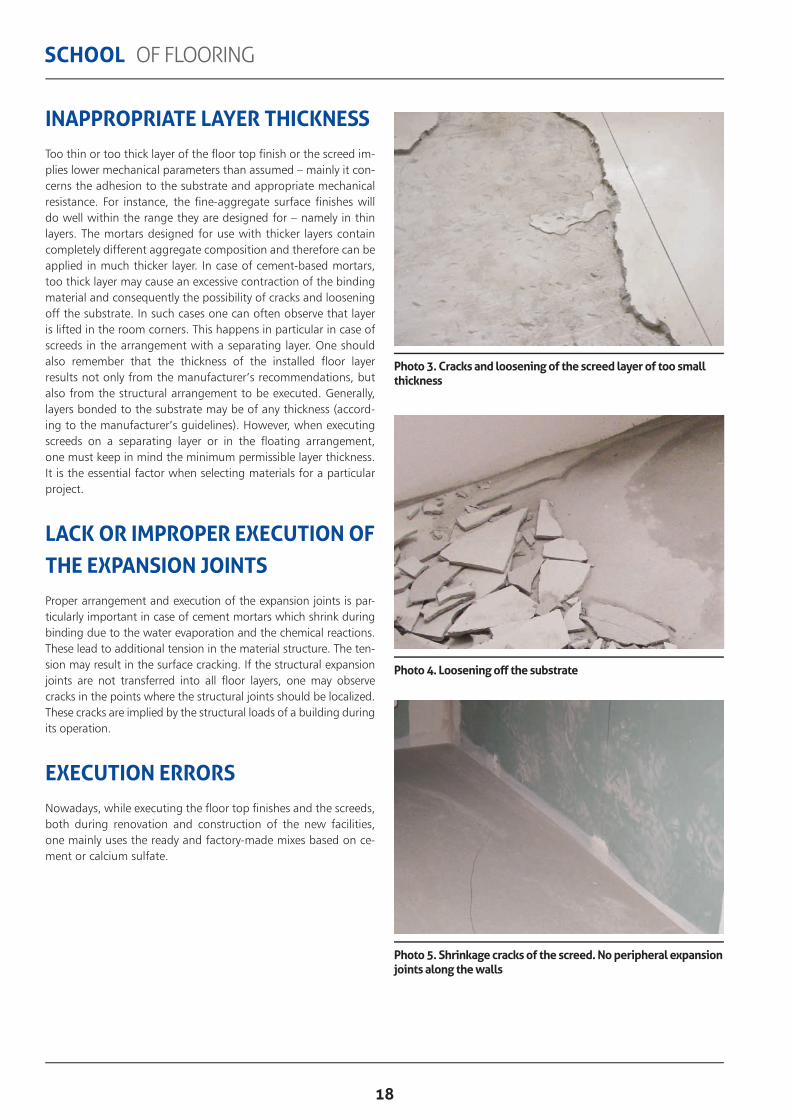
INAPPROPRIATE LAYER THICKNESSToo thin or too thick layer of the fl oor top fi nish or the screed im-plies lower mechanical parameters than assumed – mainly it con-cerns the adhesion to the substrate and appropriate mechanical resistance. For instance, the fi ne-aggregate surface fi nishes will do well within the range they are designed for – namely in thin layers. The mortars designed for use with thicker layers contain completely different aggregate composition and therefore can be applied in much thicker layer. In case of cement-based mortars, too thick layer may cause an excessive contraction of the binding material and consequently the possibility of cracks and loosening off the substrate. In such cases one can often observe that layer is lifted in the room corners. This happens in particular in case of screeds in the arrangement with a separating layer. One should also remember that the thickness of the installed fl oor layer results not only from the manufacturer’s recommendations, but also from the structural arrangement to be executed. Generally, layers bonded to the substrate may be of any thickness (accord-ing to the manufacturer’s guidelines). However, when executing screeds on a separating layer or in the fl oating arrangement, one must keep in mind the minimum permissible layer thickness. It is the essential factor when selecting materials for a particular project.
LACK OR IMPROPER EXECUTION OF THE EXPANSION JOINTSProper arrangement and execution of the expansion joints is par-ticularly important in case of cement mortars which shrink during binding due to the water evaporation and the chemical reactions. These lead to additional tension in the material structure. The ten-sion may result in the surface cracking. If the structural expansion joints are not transferred into all fl oor layers, one may observe cracks in the points where the structural joints should be localized. These cracks are implied by the structural loads of a building during its operation.
EXECUTION ERRORSNowadays, while executing the fl oor top fi nishes and the screeds, both during renovation and construction of the new facilities, one mainly uses the ready and factory-made mixes based on ce-ment or calcium sulfate.
Photo 3. Cracks and loosening of the screed layer of too small thickness
Photo 5. Shrinkage cracks of the screed. No peripheral expansion joints along the walls
Photo 4. Loosening off the substrate

19
SCHOOL OF FLOORING
effect. Excessive amount of water results in larger shrinkage of the cement mortars and may lead to cracks. It can also cause the sedimentation of the mortar aggregate. As a result thicker and heavier aggregate drops to the bottom while fi ner fi llers and chemical additives are virtually eluted and appear on the surface of the executed layer. The mortar with the excess of water nev-er achieves its designed strength parameters and is mechanically weaker. It can also cause problems while fi xing the fl oor top fi n-ish layer in the arrangement with an adhesive e.g. with tiles or parquet.
Photo 6. Cracks of the substrate
Photo 7. Appearance of surface executed with mortar containing too much water; anhydrite screed is not homogenous in colour – it is a result of the chemical additives elution
Photo 8. Addition of insuffi cient amount of water results in diffi culties in smoothing the surface fi nish
Less often (basically only in case of new constructions), one uses individually prepared mixes of particular components. The facto-ry-made dry mixes must only be mixed with the amount of water recommended by the manufacturer. However, mistakes can ha-ppen also here. The amount of water is always given in relation to the amount of binder, thus one must apply to these guidelines. Appropriate amount of water determines both the working pa-rameters of the prepared mortar and the mechanical parame-ters of the executed layer. Insuffi cient amount of water causes diffi culties in regard to proper application of a layer. Moreover, in case of self-leveling mortars one does not obtain the desired

20
SCHOOL OF FLOORING
◆ the examination of the fl oor fi nish adhesion to the substrate (it concerns the bonded fl oors only) – by gentle tapping with a wooden hammer. Characteristic thuds indicate possible delam-ination and imperfect adhesion between the applied layer and the load-bearing substrate. Loosened layer must not be accepted;
◆ the verifi cation of the executed layer thickness (optionally, on investor’s request) by cutting out square holes of 10 cm long sides in 3 randomly selected locations (at least one location per every 100 m2 of the checked area) and measuring their thickness. The measurement result should be given in increments of 1 mm. Then one should confi rm that the layer is executed in accordance to the design and the manufacturer’s guidelines.
Note! In case of screeds with the heating systems the co-mmencement of fl ooring works follows the acceptance of the heating system installation. One should pay attention to the passages of pipes or heating cables (they should be placed in special ducts), the system distribution. The pipes should be fi lled with water and their water tightness confi rmed.
Original text: Sebastian Czernik, ATLAS GroupEnglish text: Michał Gosławski, Piotr Marciniak, ATLAS Group
ACCEPTANCE OF SCREEDS AND FLOOR TOP FINISHESInformation on the principles of acceptance of screeds and fl oor fi nishes is often listed in the local technical guidelines and regu-lations. One must also take into account the guidelines included in the design, the technical specifi cation and in the agreement with the investor. The contractor and the investor (or one’s representative) should be present at the time of the acceptan-ce. In view of different possible arrangements of fl oors (bonded fl oor, on separation layer, fl oating) it is advisable to execute the intermediate acceptances despite the fi nal one. The intermediate acceptances enable to inspect the work stages and results invisi-ble after full application of the fl oor and have signifi cant impact on the correctness of the fl oor execution. During the intermediate acceptances one is able to confi rm the correctness of the subs-trate preparation, the type and the method of application of the thermal insulation or the separation layer.
1. FINAL ACCEPTANCE OF THE FLOOR SCREEDS SHOULD INCLUDE:
◆ the visual examination of the appearance of the executed screed in respect of cleanness, damp, presence of unevenness, cavities or cracks, and the required roughness;
◆ the verifi cation of the substrate evenness (in increments of 1 mm) – performed with a 2 m long control batten laid on the surface in random places and directions. In Poland the determined clearance should not exceed 3 mm, check local regulations in this respect for your country.
◆ the verifi cation of slopes (if they are required), with a 2 m long batten and a level; the measurement must be performed in incre-ments of 1 mm, the slope must be consistent, aberration from the designed level of the surface compartment should be less than -/+5 mm (for Poland, check local regulations in this respect for your country);
◆ the examination of the special areas – expansion joints, plinths etc.
2. FINAL ACCEPTANCE OF THE FLOOR FINISHES SHOULD INCLUDE:
◆ the visual examination of the appearance of the executed surface – fl oor fi nish should be evenly effaced or smoothed, of homogenous colour over the entire surface, with no cracks or scratches;
◆ the visual examination of works at the areas of expansion joints, plinths, thresholds;
◆ the verifi cation of the surface evenness – performed with a 2 m long control batten. The batten is laid on the executed surface in dif-ferent places and directions; the clearance between the lower batten edge and the surface should not exceed 3 mm (test is performed in increments of 1 mm; according to Polish regulations, check local regulations in this respect for your country). When checking the sur-face evenness one should also use a level;

www.atlas.com.pl/en

www.atlas.com.pl/en
EXPORT DEPARTMENT95-100 Zgierz (Poland), ul. Szczawińska 52ATel. (+48 42) 714 08 02Fax (+48 42) 714 08 07Mob. (+48) 607 781 018e-mail: [email protected]
CONTACT TO ATLAS/AVAL DISTRIBUTOR