Embed Size (px)
Citation preview

1©2010 Raj Jain
LL--DACS1/2 Data Link Analysis DACS1/2 Data Link Analysis Part I: Functional AnalysisPart I: Functional Analysis
Presentation to BoeingFebruary 4, 2010

2©2010 Raj Jain
OverviewOverview
Application Aeronautical Datalink Evolution Spectrum Implications of Channel Access Disciplines:
TDD vs FDD, OFDM vs TDM, Spectral efficiency Link Layer Framing Protocol Stack Link Layer Reliability Mechanisms

3©2010 Raj Jain
ApplicationApplication L-DACS = L-band Digital Aeronautical Communications
System Type 1 and Type 2 Both designed for Airplane-to-ground station communications Airplane-to-airplane in future extensions 3C: Coverage, Capacity, Cwality Range: 200 nautical miles (nm)
(1 nm =1 min latitude along meridian = 1.852 km =1.15 mile) Motion: 600 knots = 600 nm/hr = Mach 1 at 25000 ft Capacity: 200 aircrafts Workload: 4.8 kbps Voice+Data All safety-related services Data=Departure clearance, digital airport terminal information,
Oceanic clearance datalink service
4©2010 Raj Jain
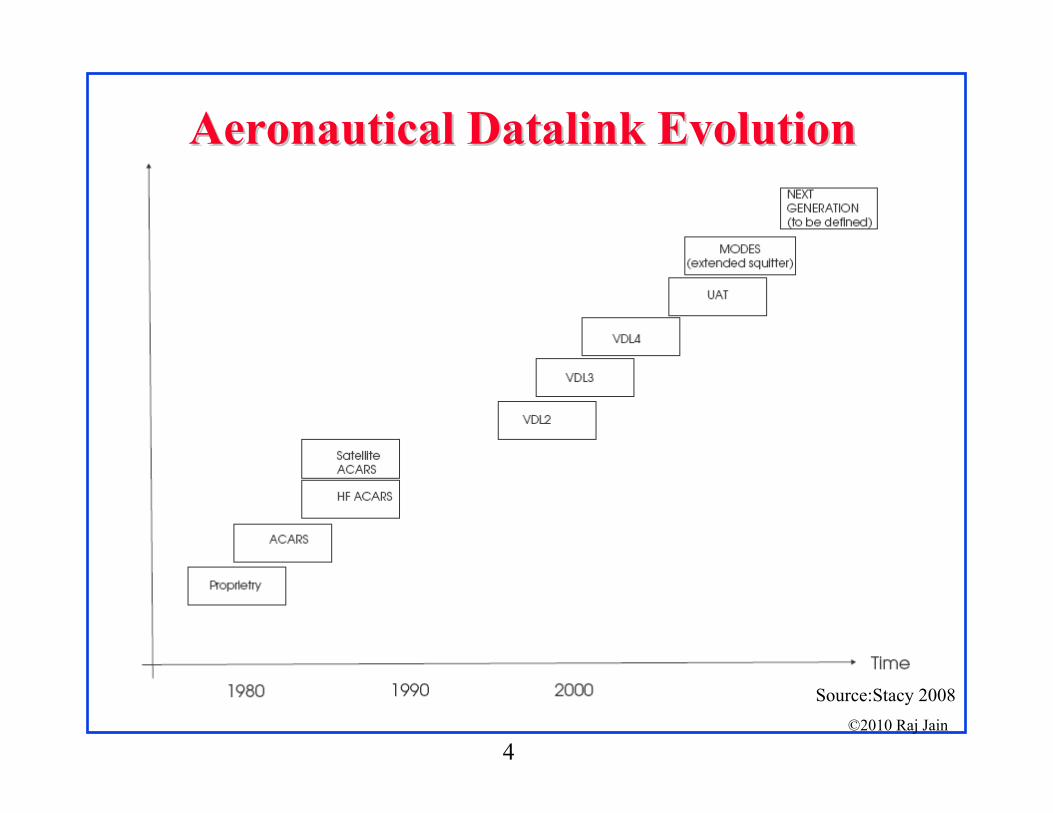
Aeronautical Datalink EvolutionAeronautical Datalink Evolution
Source:Stacy 2008

5©2010 Raj Jain
Datalink EvolutionDatalink Evolution Aeronautical radio systems Voice Digital data by modem over analog wireless VDL4 = VHF Datalink 4 in 2001 19.2 kbps over 25 kHz in VDL4 1 minute slotted frame 4 minute advance reservation B-VHF = Overlay in VHF band Costly
Change Band B-AMC = Broadband Aeronautical Multicarrier Systems in L-
Band

6©2010 Raj Jain
LL--DACS1 EvolutionDACS1 Evolution B-AMC
Overall protocol stack Medium access control cycle Data link service protocol
P34 AGC preamble concept (RL), PAPR reduction technique, MAC layer states, primitives for data transfer, … Control message formats Addressing scheme
WiMAX Tiles and chunks in the physical layer FL and RL allocation map Approach to QoS (request, scheduling, grant)
B-AMC P34 WiMAX
L-DACS1

7©2010 Raj Jain
LL--DACS2 EvolutionDACS2 Evolution
Based on GSM, UAT (Universal Access Transceiver), AMACS (All-purpose multi-carrier aviation communication system)
GSM PHY, AMACS MAC, UAT Frame Structure Both UAT and GSM use GMSK GSM works at 900, 1800, 1900 MHz
L-DACS2 is in lower L-band close to 900MHz Tested concept Price benefit of GSM components Uses basic GSM not, later enhanced versions like EDGE, GPRS, …
These can be added later.
GSM UAT AMACS
L-DACS2

8©2010 Raj Jain
SpectrumSpectrum
Source: Schnell 2008
L-Band 960-1164 MHz L-DACS1 2x498.5 kHz
FL in 985.5-1008.5MHz, RL in 1048.5-1071.5MHz, Duplex spacing 63 MHz
DME=Distance Measuring EquipmentJTIDS=Joint Tactical Information Distribution SystemMIDS=Multifunction Information Distribution SystemSSR=Secondary Surveillance RadarGSM=Global System for Mobile Communications

9©2010 Raj Jain
Spectrum (Cont)Spectrum (Cont) L-DACS2 One 200 kHz channel in lower L-Band 960-975 MHz WiFi: 20 MHz channels in 2.4 or 5.8 GHz WiMAX uses 1.25, 2.5, 5, 10, 20 MHz in 2.3, 3.5,… GHz Very early aeronautical networks used HF (3-30 MHz) Later aeronautical networks used VHF (30 MHz-300MHz) IEEE L-Band is 950-1450 MHz.
It is part of UHF (300 MHz-3GHz)Down conversion of satellite signals by low-noise blocker (LNB) results in a signal in this band.
Other L-bands are: NATO L-Band: 40-60 GHz Optical L-Band: 1565-1625 nm Infrared Astronomy L-Band: 3.5um

10©2010 Raj Jain
Effect of FrequencyEffect of Frequency Lower frequencies propagate farther Need larger cell sizes Lower frequencies are more crowded.
HF (3-30MHz) is more crowded than VHF (30-300MHz).VHF is more crowded than L-band.
Higher Frequencies have higher attenuation, e.g., 18 GHz has 20 dB/m more than 1.8 GHz
Higher frequencies need smaller antennaAntenna > Wavelength/2, 800 MHz 6”
Higher frequencies are affected more by weatherHigher than 10 GHz affected by rainfall60 GHz affected by absorption of oxygen molecules
Higher frequencies have more bandwidth and higher data rate Higher frequencies allow more frequency reuse
They attenuate close to cell boundaries. Mobility Below 10 GHz

11©2010 Raj Jain
TDD TDD vs vs FDDFDD L-DACS1 is FDD, L-DACS2 is TDD. Duplex = Bi-Directional Communication Frequency division duplexing (FDD) (Full-Duplex)
Time division duplex (TDD): Half-duplex
Most WiMAX/LTE deployments will use TDD. Allows more flexible sharing of DL/UL data rate
Good for data Does not require paired spectrum Easy channel estimation Simpler transceiver design Con: All neighboring BS should time synchronize
Base Subscriber
Base SubscriberBase SubscriberFrequency 1
Frequency 2

12©2010 Raj Jain
OFDMOFDM Orthogonal Frequency Division Multiplexing Ten 100 kHz channels are better than one 1 MHz Channel Multi-carrier modulation
Frequency band is divided into 256 or more sub-bands. Orthogonal Peak of one at null of others
Each carrier is modulated with a BPSK, QPSK, 16-QAM, 64-QAM etc depending on the noise (Frequency selective fading)
Used in 802.11a/g, 802.16, Digital Video Broadcast handheld (DVB-H)
Easy to implement using FFT/IFFT

13©2010 Raj Jain
LL--DACS1 Main System ParametersDACS1 Main System Parameters
Large number of carriers Smaller data rate per carrier Larger symbol duration Less inter-symbol interference
Reduced subcarrier spacing Increased inter-carrier interference due to Doppler spread in mobile applications
Parameter Value Channel bandwidth B 498 kHz Length of FFT Nc 64 Used sub-carriers 50 Sub-carrier spacing (498/51 kHz) f 9.76 kHz OFDM symbol duration with guard Tog 120 s OFDM symbol duration w/o guard To 102.4 s Overall guard time duration Tg 17.6 s OFDM symbols per data frame Ns 54

14©2010 Raj Jain
ModulationModulation L-DACS1: OFDM, Adaptive Coding and Modulation (ACM) L-DACS2: Single carrier, Continuous Phase Frequency Shift
Keying (CPFSK)/Gaussian Minimum Shift Keying (GMSK) GSM uses GMSK WiMAX, 11a/g/n use OFDM Advantages of OFDM:
Graceful degradation if excess delay Robustness against frequency selective burst errors Allows adaptive modulation and coding of subcarriers Robust against narrowband interference
(affecting only some subcarriers) Allows pilot subcarriers for channel estimation
Ref: http://en.wikipedia.org/wiki/Gaussian_Minimum_Shift_Keying#Gaussian_minimum-shift_keying

15©2010 Raj Jain
Data RateData Rate L-DACS1: QPSK1/2 - 64-QAM 3/4
FL (303-1373 Kbps)+ RL (220-1038 Kbps) using 1 MHz Spectral efficiency = 0.5 to 2.4 bps/Hz
L-DACS2: 270.833 kbps (FL+RL) using 200 kHz Spectral efficiency = 1.3 bps/Hz

16©2010 Raj Jain
LL--DACS1 PHY FramingDACS1 PHY Framing
RA=Random AccessDC=Dedicated ControlCC=Common ControlBC=Broadcast Control
17©2010 Raj Jain
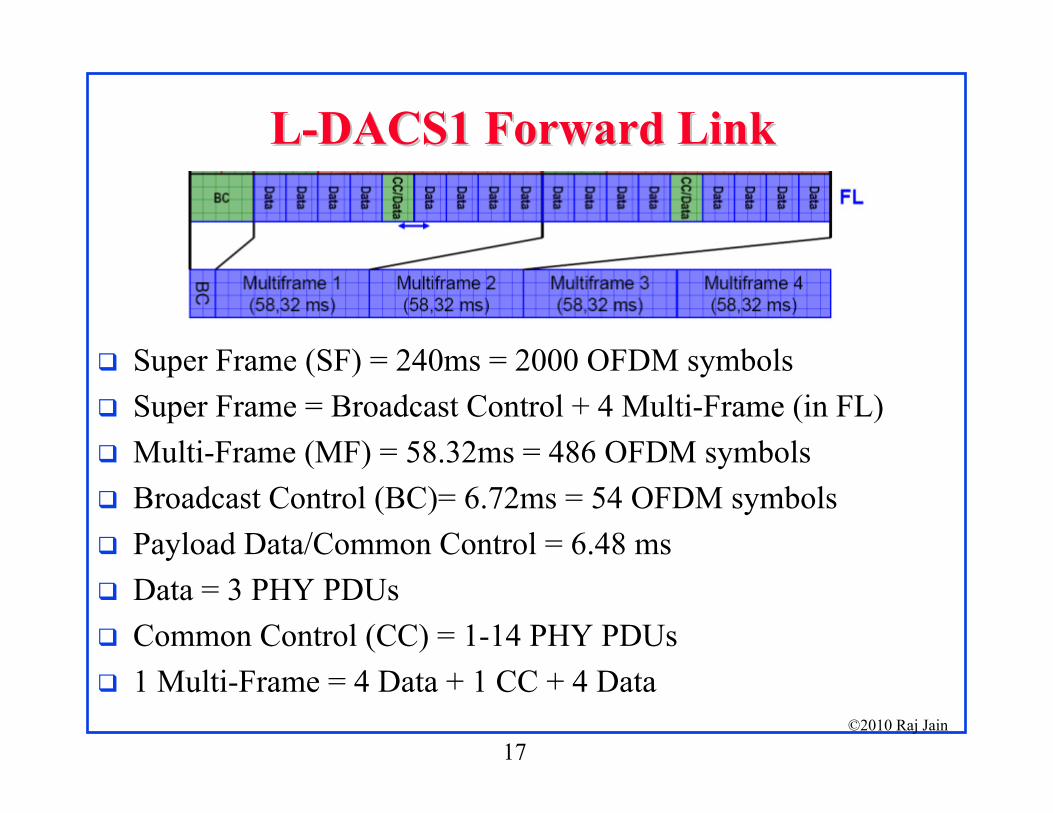
LL--DACS1 Forward LinkDACS1 Forward Link
Super Frame (SF) = 240ms = 2000 OFDM symbols Super Frame = Broadcast Control + 4 Multi-Frame (in FL) Multi-Frame (MF) = 58.32ms = 486 OFDM symbols Broadcast Control (BC)= 6.72ms = 54 OFDM symbols Payload Data/Common Control = 6.48 ms Data = 3 PHY PDUs Common Control (CC) = 1-14 PHY PDUs 1 Multi-Frame = 4 Data + 1 CC + 4 Data
18©2010 Raj Jain
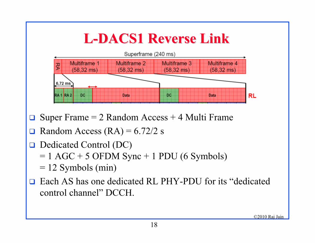
LL--DACS1 Reverse LinkDACS1 Reverse Link
Super Frame = 2 Random Access + 4 Multi Frame Random Access (RA) = 6.72/2 s Dedicated Control (DC)
= 1 AGC + 5 OFDM Sync + 1 PDU (6 Symbols) = 12 Symbols (min)
Each AS has one dedicated RL PHY-PDU for its “dedicated control channel” DCCH.

19©2010 Raj Jain
LL--DACS1 Reverse Link (Cont)DACS1 Reverse Link (Cont)
Each AS is allocated some number of tiles Tile = 25 contiguous subcarriers over 6 contiguous OFDM
symbols TDMA component in RL ensures low duty cycle
Each AS finishes fast. TDMA component reduces co-site interference impact
Co-site=Multiple antennas close to each other
Freq
20©2010 Raj Jain
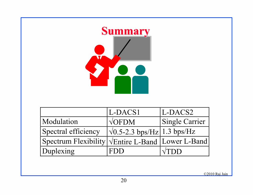
SummarySummary
L-DACS1 L-DACS2 Modulation OFDM Single CarrierSpectral efficiency 0.5-2.3 bps/Hz 1.3 bps/Hz Spectrum Flexibility Entire L-Band Lower L-BandDuplexing FDD TDD

21©2010 Raj Jain
LL--DACS1 ReferencesDACS1 References EUROCONTROL, "L-DACS1 System Definition Proposal:
Deliverable D2," Feb 13, 2009, 175 pp. EUROCONTROL, "L-DACS1 System Definition Proposal:
Deliverable D3 - Design Specifications for L-DACS1 Prototype,", April 1, 2009, 122 pp.
T. Graupl, "L-DACS 1 Data Link Layer Design and Performance," Presentation slides, ICNS Conference, 13-15 May 2009, 31 pp.
M. Schnell, "L-DACS 1 Development - Status and Preliminary Specification," Presentation Slides, 7th EUROCONTROL Innovative Research Workshops and Exhibition, Dec 2-4, 2008, 23 pp.

22©2010 Raj Jain
LL--DACS2 ReferencesDACS2 References EUROCONTROL, "L-DACS2 System Definition Proposal:
Deliverable D1," Mar 11, 2009, 116 pp. EUROCONTROL, "L-DACS2 System Definition Proposal:
Deliverable D2," May 11, 2009, 121 pp. EUROCONTOROL, "L-DACS2 Transmitter and Receiver
prototype equipment specifications: Deliverable D3," June 18, 2009, 47 pp.
L. Deneufchâtel, "LDACS 2," Presentation slides, March 25, 2009, 9 pp.
L. Deneufchâtel, "LDACS 2 Development Status and preliminary specifications," Presentation slides, Mar 12, 2008, 22 pp.

24©2010 Raj Jain
LL--DACS2 Power BudgetDACS2 Power Budget
Source: Deneufchâtel, 2009

34©2010 Raj Jain