Embed Size (px)
Citation preview

L. , c " . .
N A S A T E C H N I C A L
R E P O R T N A S A T R R - 2 9 5 2" " "-
c: /
LOAN COPY: RETURN TO
KIRTLAND AFB, N MEX AFW L [ W LI L-2)
BLUNT-BODY STAGNATION-REGION FLOW WITH NONGRAY RADIATION HEAT TRANSFER - A SINGULAR PERTURBATION SOLUTION
Langley Reseurch Center Lungley Stution, Humpton, VU.
$.
N A T I O N A L A E R O N A U T I C S A N D S P A C E A D M I N I S T R A T I O N W A S H I N G T O N , D . C . NOVEMBER 1 9 6 8
https://ntrs.nasa.gov/search.jsp?R=19690001457 2020-05-14T18:21:41+00:00Z

TECH LIBRARY KAFB, NM
00bb4b2 NASA TR R-295
BLUNT-BODY STAGNATION-REGION FLOW
WITH NONGRAY RADIATION HEAT TRANSFER, -
A SINGULAR PER.TURBATION SOLUTION
By Walter B. Olstad
Langley Research Center Langley Station, Hampton, Va.
NATIONAL AERONAUTICS AND SPACE ADMINISTRATION ____ "~ - ..
Far sale by the Clearinghouse far Federal Scientific and Technical Information Springfield, Virginia 22151 - CFSTI pr ice $3.00
. ~ ~
I .
BLUNT-BODY STAGNATION-REGION FLOW
WITH NONGRAY RADIATION HEAT TRANSFER - A SINGULAR PERTURBATION SOLUTION
By Walter B. Olstad Langley Research Center
SUMMARY
A singular perturbation solution to the blunt-body stagnation-region flow of an inviscid, radiating gas has been obtained by means of the Poincar6-Lighthill-Kuo7 o r perturbation-of-coordinates, method. A number of resul ts for a gray gas have been pre- sented in order to provide some physical insight into the effects of various parameters on the shock-layer enthalpy profiles and the radiant heat-transfer rates.
A nongray absorption-coefficient model w a s developed which includes, in an approx- imate way, the important vacuum-ultraviolet contributions of bound-free and line transi- tions. This model was used to obtain solutions pertinent to the case of reentry into the earth's atmosphere. While the resul ts are res t r ic ted to small values of the radiation cooling parameter, which characterizes the relative importance of radiation and convec- tion as energy-transport mechanisms, they cover broad ranges of vehicle velocity, altitude, and nose radius, which are of practical interest.
The characteristic enthalpy variation of the model absorption coefficient was found to be nearly independent of altitude and nose radius for fixed vehicle velocity except for velocities lower than 10.67 km/sec. Thus it w a s possible to correlate certain quantities by plotting these quantities as functions of the nondimensional adiabatic radiant heat- transfer rate for various altitudes and nose radii at fixed vehicle velocity. Among the quantities correlated w a s the cooling factor (the ratio of the stagnation-point radiant heat- transfer rate to the adiabatic radiant heat-transfer rate). The cooling-factor correlation is particularly useful because it eliminates the need to perform nonadiabatic calculations whenever radiant heat-transfer rates are desired. Also correlated w a s the factor by which the convective heat-transfer rate is reduced because of radiation losses in the shock layer. Finally, upper-bound estimates were made of the effects of absorption of precursor radiation by the free-stream air on the radiant and convective heat-transfer rates.

INTRODUCTION
At earth entry speeds near, o r in excess of, escape speed (about 11 km/sec) blunt bodies experience significant heating by thermal radiation from the hot-air shock layer. It has been shown that at these flight conditions, neither the influence of energy transport by radiation on the thermodynamic and flow properties of the shock-layer gas nor the non- gray character of the absorption coefficient of the gas can be ignored if reasonable quan- titative estimates of radiant heat-transfer rates are to be obtained. (See, for example, refs. 1, 2, and 3.)
Even though these heating rates are large (from the point of view of heat protection), the rate at which energy is transported by radiation is small compared with the rate at which energy is transported by the flow for a broad range of conditions of practical inter- est . As a result the flow propert ies are only slightly perturbed from the radiationless case. Goulard (ref. 4) took advantage of this fact and developed what amounted to a f i rs t - order perturbation solution of the temperature distribution in the inviscid stagnation region of an optically thin, gray, gas layer. This first-order result corresponds to the case of a gas which radiates at a constant rate regardless of its local thermodynamic state.
A second-order perturbation solution w a s obtained in reference 2. This solution includes the effects of temperature-varying thermodynamic and optical properties, which are very important because of the strong temperature dependence of these properties. However, it was found that the conventional perturbation expansion diverged in the vicinity of the body surface, and this fact indicates that the problem is of the singular perturba- tion type. The Poincarb-Lighthill-Kuo (P-L-K), or perturbation-of-coordinates, proce- dure was used to obtain a uniformly valid perturbation expansion. This solution was then used to study the effects of various parameters for an idealized gray gas. These results (originally presented in ref. 2) are presented herein to provide some physical insight into the nature of the influence of the several parameters.
A nongray absorption-coefficient model based on recent published information on the radiative properties of high-temperature air is presented. This model, which includes the important features of the vacuum-ultraviolet bound-free continuum and line contribu- tions, was used in conjunction with the singular perturbation solution to calculate the flow- field properties and stagnation-point radiant heat-transfer rates over a range of free- stream velocities (7.92 to 15.24 km/sec), altitudes (30.48 to 73.15 k m ) , and nose radii (1 to 1000 cm). A cooling factor, which represents the decrease in radiant heat-transfer rate due to radiation cooling of the shock-layer gas, is defined and a correlation in terms of the adiabatic (or isothermal slab) radiant heat-transfer rate is presented. A correla- tion of the approximate decrease in convective heat-transfer rate due to radiation cooling is also presented.
2 I

The effects of absorption of precursor radiation and of absorption in an ablated vapor layer were not included in the calculations. However, if emission is small com- pared with absorption in both the free stream and ablated vapor layers (a physically rea- sonable assumption because of the relatively low temperatures), the effects of these phe- nomena can be determined separately and the results of this paper modified by simple correction factors. Upper bounds to the correction factors for the increase in radiant and convective heat-transfer rates due to absorption of the precursor radiation are pre- sented. No attempt was made to determine the radiation-blocking effect of the ablated vapor layer.
SYMBOLS
a constant in equation (2)
B nondimensional blackbody emissive power, T4/Ts4
Bi integral of nondimensional Planck function for ith step
nondimensional Planck distribution function, Planck distribution function 0 4 7 T s
cP,S specific heat at constant pressure immediately behind shock, cm2/sec2-'K
En 00
exponential integral function of order n; En(y) = ll e-Ytt-ndt
F function defined by equation (A60)
F C cooling factor, - qR,w
qR,w ,a
f nondimensional stream function
f n nth-order coefficient in perturbation expansion of f
f n* nth-order coefficient in P-L-K expansion of f
H function defined by equation (A64)
3

nondimensional enthalpy, Enthalpy 1 2 5 WKI
value of h at the edge of the viscous boundary layer
nth-order coefficient in perturbation expansion of h
nth-order coefficient in P-L-K expansion of h
radiant f l u x for wavelength interval (hl,X2) emitted from one side of infinite s l ab of thickness L, W/cm2
monochromatic radiant flux absorbed by wall (stagnation point), W/cmS-sr
Bouguer number,
thermal conductivity immediately behind shock, W/cm-OK
slab thickness, cm
Pgclet number (product of Reynolds number and Prandtl number),
PrnWoocp,sAa/ks
nondimensional convective heat f l u x at wall (stagnation point), Convective heat f l u x
nondimensional divergence of radiant-heat-flux vector, Divergence of radiant-heat-flux vector ~- _ _ _
function defined by equation (A65)
nth-order coefficient in the perturbation expansion of qR'
4

qR,s
qR,w
qR,w,a
RN
RS
r
rO,X’ r l ,X
r W
S
T
TS
U
wca
* wca
W
X
z
nondimensional radiant heat f l u x leaving front of shock layer in upstream
direction, Radiant heat flux leaving front of shock layer 1 3 5 P-Wca
nondimensional radiant heat flux absorbed by wall (stagnation point), Radiant heat flux absorbed bv wall
nondimensional adiabatic radiant heat f l u x absorbed by wall (stagnation point)
nose radius in vicinity of stagnation streamline, cm
shock radius in vicinity of stagnation streamline, cm
radial coordinate, cm
quantities defined by equations (16) and (21), respectively
coefficient of surface reflectivity
exponent in equation (46)
temperature, O K
temperature immediately behind normal shock, O K
radial component of velocity, cm/sec
free-stream velocity, cm/sec
effective free-stream velocity, w,J1 + mR,s, cm/sec
axial component of velocity, cm/sec
transformed nondimensional Dorodnitsyn coordinate
axial coordinate, cm
5

step heights in absorption-coefficient model for line contribution
relative density of gray background in absorption-coefficient model for line contribution
fraction of precursor radiation.absorbed by free stream in path of body Y
shock standoff distance, cm A
shock standoff distance for nonradiating (adiabatic) shock layer, cm A a
- A ratio of shock standoff distance for radiating and nonradiating shock layer,
A/Aa
4 f l s 4 k p radiation cooling parameter,
P,W, 3 E
stretched boundary-layer coordinate defined by equation (A61)
nondimensional Dorodnitsyn coordinate ‘ thickness of viscous boundary layer in terms of 7
shock location in terms of r]
nth-order coefficients in perturbation expansion of qA ‘A ,n
Vn *
e1,e2
nth-order coefficient in P-L-K expansion of 17
quantities defined by equations (A39) and (A40), respectively
nondimensional Planck mean mass absorption coefficient, Planck mean mass absorption coefficient
K p7s
KP
Planck mean mass absorption coefficient at conditions immediately behind normal shock, cm2/g
K P ,s
6
-. . . . ..

Kx nondimensional monochromatic mass absorption coefficient, Monochromatic mass absorption coefficient
KP,S
x wave length ,
xl,x2 endpoints of wavelength interval,
- P Planck mean linear absorption coefficient, cm-1
Pi linear absorption coefficient for ith step, cm-1
5 variable of integration
P nondimensional density, Density PS
PO standard sea-level density of air, 1.225 X g/cm3
PS density immediately behind normal shock, g/cm3
p, free-stream density, g/cm3
P,* effective free-stream density, p,
z(X1J2) volume absorption coefficient averaged over wavelength interval x1,x2 , cm-1 0
0 Stefan-Boltzmann constant, 5.6697 X W/cm2-OK4
7 x
@C
r normalized optical path length in a gray gas, Optical path length kP
normalized monochromatic optical path length, Optical path length
kP
factor for increase of convective heat-transfer rate when absorption of precursor radiation by free s t ream is taken into account
7
@R factor for increase of radiant heat-transfer rate when absorption of precursor radiation by free s t ream is taken into account
%+2 functions defined by equations (17) and (22), respectively
@1,@2 quantities defined by equations (A37) and (A38), respectively
X density ratio across normal shock, p,/bs
+ 1 7 + 2 quantities defined by equations (A41) and (A42), respectively
Dots indicate derivatives with respect to ho.
Primes indicate derivatives with respect to 7.
ANALYSIS
Stagnation-Region Flow Model
Available numerical solutions indicate that a reduction from a three-dimensional to a nearly equivalent one-dimensional problem can be carried out in the stagnation region. (See, for example, ref. 5.) This simplification can be applied because the flow behind a strong bow shock is nearly incompressible in the stagnation region. Also, the various thermodynamic properties are nearly independent of the lateral or radial coordinate. While the same arguments apply in the stagnation region of a radiating shock layer, it is not possible to postulate the existence (even approximately) of a one-dimensional solution solely on this basis. Some additional assumption is required regarding the effect of the far field on the radiant heat flux and its divergence. This effect is not known a pr ior i as it depends on the solution to the entire flow field. Fortunately, the shock layer is thin and only a small portion of the radiant energy emitted by gas removed from the stagnation region actually passes through the stagnation region. If absorption is small , only a smal l portion of this energy is absorbed in the stagnation region. On the other hand, if absorp- tion is large, the beam is greatly attenuated when it reaches the stagnation region, and only a small portion of the energy which started the journey is absorbed there. The divergence of the radiant flux is influenced only by the amount of energy absorbed and emitted. Consequently, the far-field effect on the divergence of the radiant flux is a result of that small. portion of radiant energy originating in the far field and absorbed in the stag- nation region. In the transparent and optically thick limits, this effect of the far field vanishes.
It would appear from the foregoing discussion that a stagnation model for a radiating gas can be postulated as long.as the assumptions concerning the far field are not grossly
8
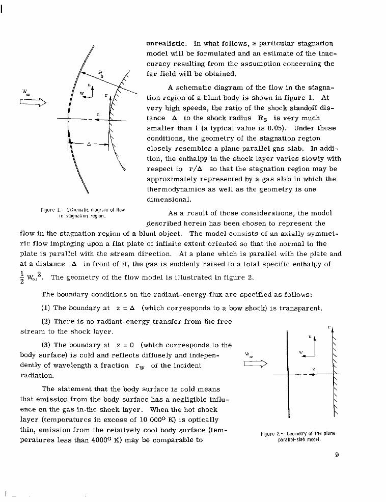
Figure 1.- Schematic diagram of flow i n stagnation region.
unrealistic. In what follows, a particular stagnation model will be formulated and an estimate of the inac- curacy resulting from the assumption concerning the far field will be obtained.
A schematic diagram of the flow in the stagna- tion region of a blunt body is shown in f igure 1. At very high speeds, the ratio of the shock standoff dis- tance A to the shock radius Rs is very much smaller than 1 (a typical value is 0.05). Under these conditions, the geometry of the stagnation region closely resembles a plane parallel gas slab. In addi- tion, the enthalpy in the shock layer varies slowly with respect to r/A so that the stagnation region may be approximately represented by a gas slab in which the thermodynamics as well as the geometry is one dimensional.
A s a result of these considerations, the model described herein has been chosen to represent the
flow in the stagnation region of a blunt object. The model consists of an axially symmet- r ic flow impinging upon a flat plate of infinite extent oriented so that the normal to the plate is parallel with the stream direction. At a plane which is parallel with the plate and a t a distance A in front of it, the gas is suddenly raised to a total specific enthalpy of 1 2 W, . The geometry of the flow model is illustrated in figure 2.
The boundary conditions on the radiant-energy flux are specified as follows:
(1) The boundary at z = A (which corresponds to a bow shock) is transparent.
(2) There is no radiant-energy transfer from the free stream to the shock layer.
(3) The boundary at z = 0 (which corresponds to the body surface) is cold and reflects diffusely and indepen- w m
dently of wavelength a fraction rw of the incident 0 radiation. ___
The statement that the body surface is cold means that emission from the body surface has a negligible influ- ence on the gas in-the shock layer. When the hot shock layer ( temperatures in excess of 10 OOOO K) is optically thin, emission from the relatively cool body surface (tem- peratures less than 4000O K) may be comparable to parallel-slab model.
Figure 2.- Geometry of the Plane-
9

emission from the shock-layer gas. However, because the shock layer is optically thin, very little of the radiant energy emitted by the body surface will be absorbed by the shock- layer gas. On the other hand, when the shock layer is optically thick and absorption is important, the shock-layer gas emission will approach the blackbody value corresponding to the high temperature of the shock layer. Since blackbody radiation is proportional to the fourth power of temperature, the energy emitted from an optically thick gas layer will greatly exceed that emitted from the body surface. Thus, whenever the body surface tem- perature is small compared with the shock-layer temperature, the influence of emission from the body surface on the shock-layer gas is unimportant.
Governing Equations
The governing nondimensional equations for the proposed inviscid stagnation flow model are
The boundary conditions are
f(0) = 0 (3)
The quantity psAaq is the Dorodnitsyn coordinate, 2p,W,f(q) the stream function,
- Wm2h(q) the total enthalpy, - p,Wm qR'(q) the divergence of the radiant heat-flux 1 1 3 2 2 vector, Aa the adiabatic (or radiationless) shock standoff distance, Rs the shock radius, x = p,/ps the density ratio across the shock, and psp the density. The sub-
scr ipt s has been used to denote dimensional quantities immediately behind the normal shock. The quantity p,AaqA defines the location of the shock in terms of the Dorodnitsyn coordinate.
10

This system of equations is similar to the system obtained by Howe and Viegas (ref. 6) when viscosity, thermal conductivity, and curvature effects are neglected. A complete derivation of the system of equations (1) to (6) is presented in reference 2. Implicit in this derivation is the strong-shock assumption, which leads to the neglect of the normal pressure gradient. The shock standoff distance (and, hence, the constant a) is related to the lateral pressure gradient and the density ratio through the Rankine- Hugoniot conditions ac ross a spherical shock.
The nondimensional form of the divergence of the radiant f l u x vector was also derived in reference 2:
The quantity K ~ , ~ K ~ is the Planck mean mass absorption coefficient, K ~ , ~ K ~ the
monochromatic mass absorption coefficient, fls4B/7r the blackbody emissive power, f l s4B 7r the Planck function, and En the exponential integral functions of order n. The optical path length is
A I
It is the presence of the second and third terms on the right-hand side of equa- tion (7) which so greatly complicates the radiation problem. These terms are integral expressions. In addition, their presence makes it impossible to define a wavelength- averaged absorption coefficient by which the wavelength dependence might be eliminated. The importance of these terms is indicated by the magnitude of the Bouquer number, k p = psKp,sAa, which is the ratio of the shock standoff distance for a nonradiating shock layer to the photon mean free path evaluated a t conditions immediately behind the shock.
The radiation cooling parameter, E = ( 40Ts4 / p,W, 3) kp, admits of several physical
interpretations which are useful in the understanding of the radiating shock layer. Of these, one of the most useful is the following:
of emission from element of Time required by element of volume to of gas emerging from shock distance A a at ra te of emergence from shock
E = )( 2(Energy of element of volume upon emergence from shock)
11
I
This parameter modifies the entire radiation term, and thus it is a measure of the effi- ciency of radiation compared with convection as an energy transport mechanism within the shock layer. In addition, the surface reflectivity rw and the wavelength dependence of the absorption coefficient influence the character of the radiation terms and will 'be considered as parameters in this study.
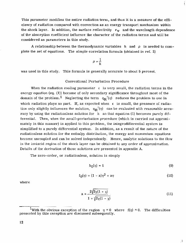
A relationship between the thermodynamic variables h and p is needed to com- plete the set of equations. The simple correlation formula (obtained in ref. 2)
1 p = - h
was used in this study. This formula is generally accurate to about 5 percent.
Conventional Perturbation Procedure
When the radiation cooling parameter E is very small , the radiation terms in the energy equation (eq. (1)) become of only secondary significance throughout most of the domain of the prob1em.l Neglecting the term qRf(q) reduces the problem to one in
which radiation plays no part. If, as expected when E is small, the presence of radia- tion only slightly influences the solution, qRf(q) can be evaluated with reasonable accu- racy by using the radiationless solution for h so that equation (1) becomes purely dif- ferential. Then, when the small-perturbation procedure (which is carried out approxi- mately in this manner) is applied to this problem, the integrodifferential system is simplified to a purely differential system. In addition, as a resul t of the nature of the radiationless solution for the enthalpy distribution, the energy and momentum equations become uncoupled and can be solved independently. Hence, analytic solutions to the flow in the inviscid region of the shock layer can be obtained to any order of approximation. Details of the derivation of these solutions are presented in appendix A.
The zero-order, o r radiationless, solution is simply
where
'With the obvious exception of the region 7 0 where f(7) 0. The difficulties presented by this exception are discussed subsequently.
12

The first-order solution, which represents the effect of radiation when the optical and thermodynamic properties of the gas are assumed to be independent of the enthalpy, is
Here 5 is a dummy variable of integration. The quantity q ' ( q ) is given by the for mula
R, 0
The notation has been simplified somewhat in this expression by omitting the argument ho in the terms K~ and Bh and by introducing the quantities
kA = kpKA (15)
Also
The second-order solution takes changes in enthalpy. This solution is
into account the change in gas properties with

where
Here the argument ho is omitted in the terms ik and Bk and the quantity '1 X is defined by the expression
7
Also
The quantities qA,0, vA,1, and qA72 are given by the formulas
It can be seen upon inspection of equation (20) that a large ra te of change of the absorption coefficient with enthalpy will lead to large values of q ' (7). Thus, it is clear that for conditions of interest , for which the absorption coefficient does vary strongly with enthalpy, the second-order solutions can become more important to the overall solution than their order in 6 might at first indicate.
R71
14

I
Perturbation-of-Coordinates Procedure
As can be seen from an inspection of the expressions (12) and (18), the first-order solution for the enthalpy distribution has a logarithmic singularity at the point q = 0 and the second-order solution has a singularity of greater strength at this point. As a con- sequence, the assumed expansion diverges as the origin is approached and the small- perturbation solution is not uniformly valid throughout the domain of the problem. This divergence can lead to serious errors in the calculation of the radiant heat flux to the wall because those regions close to the wall, in which the largest errors occur , are given the most weight in the calculation. This is particularly true for shock layers that are not optically thin. Additional difficulties are encountered when attempting to specify the proper outer boundary conditions for the viscous boundary-layer equations. In classical boundary-layer theory, the outer boundary conditions are obtained from the values of the outer (or inviscid) solution at the wall (q = 0 in this problem). Because of the divergence of the outer solution, no finite value exists at q = 0.
In this section the method of perturbation of coordinates2 (ref. 7) is used to obtain a solution which is uniformly valid over the domain of the problem. Details of the appli- cation of this method to the problem of this paper are presented in appendix A. This method uses a coordinate transformation in the form of a perturbation expansion of the coordinate to remove the singularity (which caused the divergence of the conventional solution) from q = 0 to a small negative value of q which lies outside the domain of the problem. The perturbation-of-coordinate expansions are
f ( V , € ) = fO*(X) + €fl*(X) + . . . (28)
where x is the coordinate in the transformed plane, and the asterisk has been used to differentiate between the coefficients in the perturbation-of-coordinate expansion and the coefficients in the conventional expansion. Pritulo (ref. 8) has derived a general relation between the coefficients in the two types of expansion. Adapted to this problem, the rela- tionships became
hl*(x) = hl(x) (30) ~~
2Variously called the Poincar6-Lighthill-Kuo method, the P-L-K method, the P-L method, Lighthill's technique, and the method of strained coordinates.
15
The second-order term h2(x) introduces the effects of variable thermodynamic and optical properties, so it is apparent that these effects are contained in the first-order perturbation-of-coordinate solution.
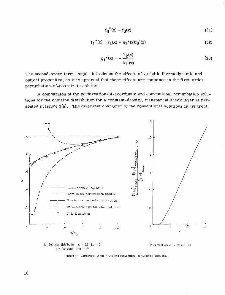
A comparison of the perturbation-of-coordinate and conventional perturbation solu- tions for the enthalpy distribution for a constant-density, transparent shock layer is pre- sented in figure 3(a). The divergent character of the conventional solutions is apparent.
1.0
.a
.6
h
.4
.2
0
( a ) Enthalpy distribution. E = 0.1; kp = 0; p = Constant; K P B = h6.
f m
t
/ / Exact solution (eq. (34))
I " First-order perturbation solution
" _ " Zero-order perturbation solution
i --- Second-order perturbation solution
-a) 0 P-L-K solution
E
(b) Percent error i n radiant flux.
Figure 3.- Comparison of the P-L-K and conventional perturbation solutions.
16
Also shown in the figure is the exact analytic solution, which can be found in this simple case. The formula for this exact solution is
where d (the exponent in the correlation formula K ~ B = hd) was taken to be 6 and the constant a (which appears in the momentum equation, eq. (2)) was taken to be 0.5. The good agreement between the perturbation-of-coordinate solution and the exact solution indicates that the accuracy of the perturbation-of-coordinate solution is probably second- order in the radiation cooling parameter E throughout the domain, except perhaps in the immediate neighborhood of the wall. It is clear that quantities such as the radiant heat f lux at the wall, which depend upon an integration over the enthalpy distribution, will be considerably more accurate i f the perturbation-of-coordinate solution rather than the con- ventional perturbation solution is used.
The percent error in radiant heat f l u x is presented as a function of E in f igure 3(b). The e r ro r is less than 12 percent for values of E no larger than 0.3.
It should be noticed that the perturbation-of-coordinate solution does not lead to zero enthalpy at the wall as the exact transparent solution does. The reason for this disparity can be found in the fact that the coordinate stretching displaces the boundary with regard to both the energy and momentum equations but not by a uniform amount. Thus a physical interpretation of the first-order perturbation-of-coordinate solution is that the normal velocity of the flow at the boundary for the energy equation is not quite zero, and a particle approaching this boundary will reach i t in a finite time before losing all i ts energy by radiation.
Since the expected error in the Dorodnitsyn coordinate 7 i n t e r m s of the stretched coordinate x is of order €2 and since the gradients in hl(x) are very large in the vicinity of the wall, the difference between the perturbation-of-coordinate and exact solu- tions at the wall lies within expected limits. Convergence to the correct solution should be attained with the addition of higher order terms to the expansions of h and 7.
RESULTS AND DISCUSSION
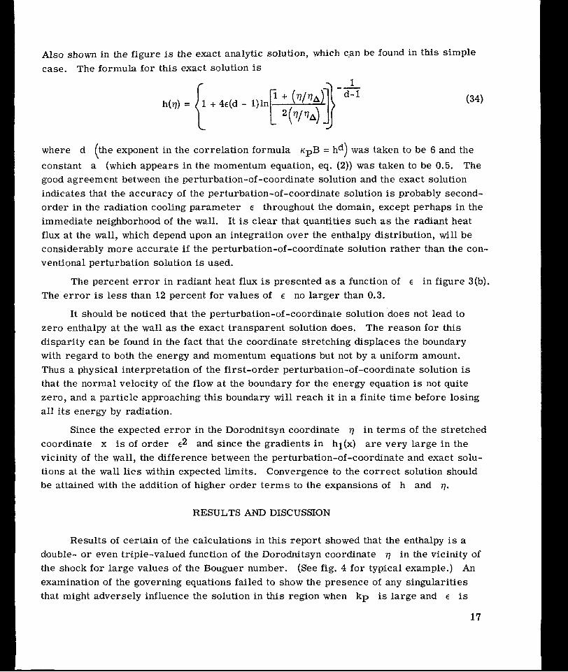
Results of cer ta in of the calculations in this report showed that the enthalpy is a double- o r even triple-valued function of the Dorodnitsyn coordinate 7 in the vicinity of the shock for large values of the Bouguer number. (See fig. 4 for typical example.) An examination of the governing equations failed to show the presence of any singularities that might adversely influence the solution in this region when k p is large and E is
17
small. On the other hand, the results of calculations with varying mesh size seemed to rule out the possibility that this physically unrealistic behavior can be attributed solely to numerical inaccuracies. Consequently, it is suspected that the difficulty results from the large first and second derivatives of h(q) just behind the shock, which can lead to
Figure 4.- Example of triple-valued solution. E = 0.1; K P = 10 ; KP = 4; rw = 0.
values of ql*(x) very much larger than 1. This behavior is to be expected because of
the boundary-layer type of behavior of the enthalpy just behind the shock for an optically thick shock layer (see ref. 2). It is suspected that inclusion of higher order terms in expansions would either eliminate the problem or increase the value of k p at which it first appears. For truncation after the second-order terms the condition for validity of the solution appears to be Ekp < 1.
Gray-Gas Results
Shock-layer enthalpy distributions for a gray gas with differing values of the radia- tion cooling parameter E, the Bouguer number kp, the variation with enthalpy of the Planck mean mass absorption coefficient kp, and the reflectivity of the body surface rw are presented in f igures 5 to 7. While the gray-gas assumption may not be realist ic for most gases of interest , i t s use is felt to be justified in the study of these parameters for two reasons. First, the highly complex and varied spectral structure of absorption coef- ficients makes a general parametric study of nongray gases impractical. Second, experi- ence with nongray calculations indicates that the qualitative dependence of the gray results on the various parameters will carry over to most nongray cases.
18

I
1.0
.8
.6
h
.4
.2
0
1 .o
.8
.ii
h
.4
.2
C
1
.2 a .* .6 .a 1 .o . "
(a) E = 0.01.
)--- " ."
- 1.0
.2 .4 .6 .8 1 .o
&A
(b) E = 0.03.
Figure 5.- Effect of the parameters E and kp on the shock-layer enthalpy distribution. Kp = 4.0.
19
I

The value of x, the density ratio across the normal shock, was fixed at 0.06 for the calculations reported on in this section. This choice is justified because x var ies but little with altitude and velocity and the effects of this variation on the stagnation solu- tions are slight. The value x = 0.06 is typical for hypervelocity flight in the atmo- sphere of the earth.
1.0
.8
.6
h
.4
.2 .4 .6 .8 1.0
(c) E = 0.10.
Figure 5.- Concluded.
The decrease in enthalpy level with increasing E is illustrated in figures 5(a) to 5(c). These results indicate that the loss of energy from the shock layer by radiation (i.e., radiation cooling) can produce a noticeable drop in enthalpy for values of E as small as 0.01, The dependence of the enthalpy distribution on the Bouguer number (hence, optical thickness) is also shown in these figures. As expected, an increase in the Bouguer number (or optical thickness) inhibits shock-layer cooling and leads to higher values of enthalpy near the wall.
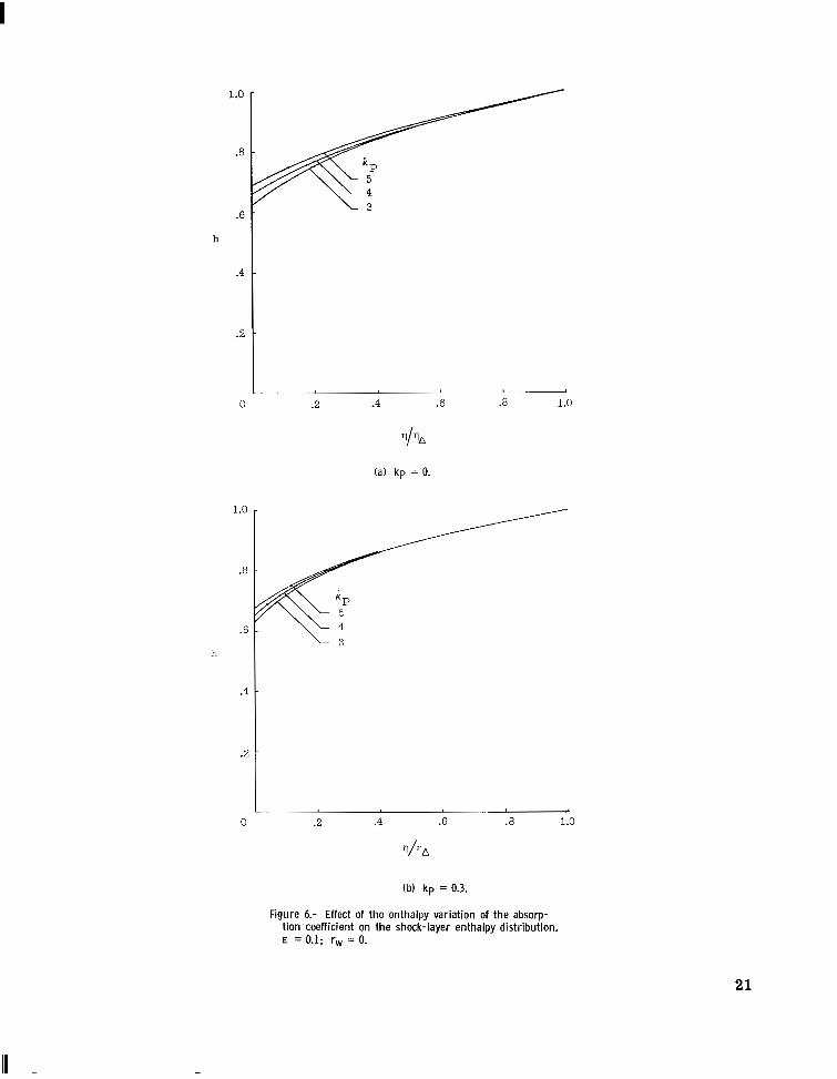
The variation of the enthalpy distribution with iP (the enthalpy variation of the Planck mean mass absorption coefficient) for several values of the Bouguer number kp
is shown in figures 6(a) to 6(c). These effects are most noticeable for optically thin shock
and tend to vanish as the optical thickness increases. In a transparent
20
1.0
.8
.6
h
.4
.2
0
1.0
.8
.6
h
.4
.2
0
.2 .4 .6 .8 1.0
(a) kp = 0.
.2 .4 .6 .E 1.0
(b) kp = 0.3.
Figure 6.- Effect of the enthalpy variation of the absorp- tion coefficient on the shock-layer enthalpy distribution. E = 0.1; rw = 0.
21

layer, the rate of emission of radiant energy is proportional to the Planck mean mass absorption coefficient KP. Thus, gases with small values of ip (which mean larger values of K~ when the nondimensional enthalpy is less than 1) will be cooled more than gases with large values of ip . As the optical thickness increases, a smaller value of kp still implies greater emission rates but it also means greater absorption and more
0 .2 .4 .6 .8 1 .0
4% ( C ) kp = 1.0
Figure 6.- Concluded.
radiant energy available for absorption. The process of absorption tends to counteract the differences in emission rates due to differences in ip . Finally, when radiation equi-
librium is reached (this state is achieved in the interior of optically thick regions), the energy of the particle is independent of i ts optical properties. Of course, in those regions optically close to the shock and the wall the amount of radiant energy available for absorp- tion is not so great as in the interior of the shock layer, and particles in these regions cannot approach the state of radiation equilibrium (except in a region optically close to a perfectly reflecting surface). Thus, the enthalpy distribution remains dependent on the value of ip near the shock and the wall. This dependence of kp is suppressed near
the shock, where h is almost 1, because the values of K~ are nearly the same despite the differences in ip .
22

The effect of surface reflectivity rw on the shock-layer enthalpy distribution is shown in figures 7(a) to 7(c). If the shock-layer gas is transparent (i.e., the gas does not absorb), surface reflectivity has no effect on the enthalpy distribution because all photons emitted by the layer escape. Whether or not a photon is absorbed or reflected by the wall is of no consequence. As the optical thickness of the layer is increased, the
chance of
0 .2 .4 .G .8 1 .o
(a) kp = 0.1.
Figure 7.- Effect of surface reflectivity on the shock-layer enthalpy distribution. E = 0.1; Kp = 4.0.
capture of a photon by absorption in the layer is increased. If the surface reflectivity is increased also, the probability of capture is increased st i l l further because many photons which might otherwise have escaped into the wall are reflected back into the layer and are once again subject to capture there. Consequently, the enthalpy level is higher near a reflecting wall than it would be near a nonreflecting wall.
It can be concluded from the foregoing discussion that use of a reflecting surface will not reduce the radiant heat-transfer rate from the gas to the wall by the factor 1 - rw (unless, of. course, the gas is transparent) but will reduce it by some smaller fraction. The reason is that the radiant heat f l u x incident on the wall is larger when the wall is reflecting because of the higher enthalpy level. In addition, the ra te of heat trans- ferred to the wall by conduction will be greater, also because of the higher enthalpy level.
23

1 .o
.8
.6
h
.4
.2
0
1 .o
.8
.6
h
.4
.2
0
\\ .2
.2 .4 .6 .8 1.0 1- I . . 1 "
(13 kp = 3.0.
Figure 7.- Concluded,
24
Of course, increasing the surface reflectivity always decreases the total heat-transfer rate to the wall because the higher enthalpy level must lead to an increased loss of energy by radiation through the shock in the upstream direction and by convection in a lateral direction away from the stagnation point.
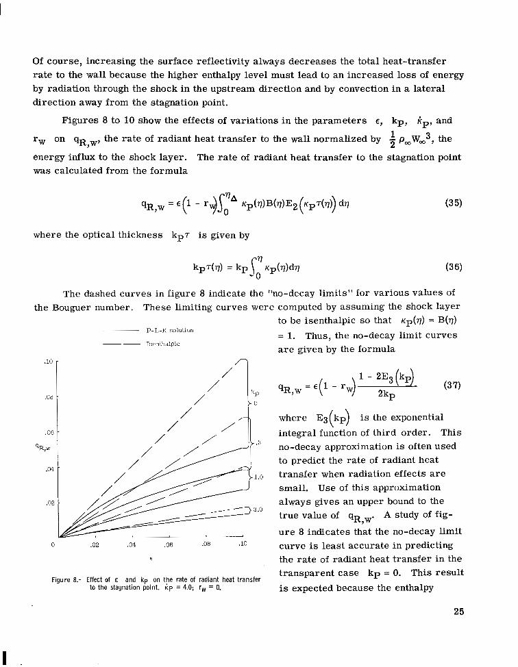
Figures 8 to 10 show the effects of variations in the parameters E, kp, k,, and
rw on qR,w, the rate of radiant heat transfer to the wall normalized by 1 p,WW3, the
energy influx to the shock layer. The rate of radiant heat transfer to the stagnation point was calculated from the formula
where the optical thickness kpT is given by
The dashed curves in figure 8 indicate the “no-decay limits” for various values of the Bouguer number. These limiting curves were computed by assuming the shock layer
.lo
.ox
.Of
%,VI
.04
.0;
P-L-K solution
Iwnthalpic “
/ /-
/ /
/ / /’
kP -0
0 .02 .04 .06 .08 .10
E
Figure 8.- Effect of E and kp on the rate of radiant heat transfer to the stagnation point. i p = 4.0; rw = 0.
to be isenthalpic so that K,(v) = B(7)
= 1. Thus, the no-decay limit curves are given by the formula
where E3(kp) is the exponential integral function of third order. This no-decay approximation is often used to predict the rate of radiant heat transfer when radiation effects are small. Use of this approximation always gives an upper bound to the true value of qR,w. A study of fig-
u r e 8 indicates that the no-decay limit curve is least accurate in predicting the rate of radiant heat transfer in the transparent case k p = 0. This resul t is expected because the enthalpy
25

distribution for the transparent case is the .06 -
k P most perturbed from an isenthalpic state. 0 Results presented in this figure also indi-
cate the importance of absorption (as char- acterized by the Bouguer number kp) in .04 ---.. . - .- - -
.3
'R,w 1.0 " ~ . . " ~ . . . reducing the rate of radiant heat transfer
.02 - from the shock layer to the wall.
The results presented in f igure 9 indicate that the differences in kp are
0 L
3 ,-------"""---------------I 4 5 most important when the optical thickness
KP of the shock layer is small. Here the radi- ant heat transfer to the wall is greatest for
Figure 9.- Effect of the enthalpy variation of the absorption coefficient on the rate of radiant heat transfer to the the smallest value of ip. This, of course, stagnation point. E = 0.1; rw = 0. supplements the observation (from fig. 6(a))
- that radiation cooling is greatest for gases in which iP is least. The differences in radiant heat transfer to the wall brought about
by differences in the value of ip tend to vanish as the optical thickness of the layer increases.
The reduction in radiant heat transfer to the wall due to surface reflectivity is shown in f igure 10. When the shock layer is transparent, the rate of radiant heat trans- f e r r ed qR is in the ratio 1 - rw. However, as the optical thickness of the shock
layer increases, the ratio becomes somewhat greater than 1 - rw as predicted earlier ,w
in this section.
The effect of the parameters E , K ~ , and rw on the shock
standoff distance is shown in fig- u r e s 11 and 12. The quantity x is the ratio of the shock standoff distance in a radiating shock layer to that in a nonradiating (or adiabatic) shock layer at the same flight conditions. It was computed from the formula
.04
Figure 10.- Effect of surface reflectivity on the rate of radiant heat transfer to the stagnation point. E = 0.1; I+ = 4.0.
26
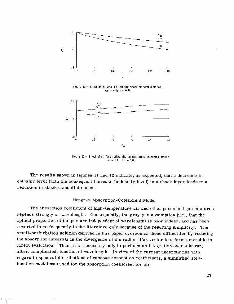
1.0
- A .9
.0 I 3 .02 .04 .06 .08 .10
1 ”
E
Figure 11.- Effect of E and kp on the shock standoff distance. Kp = 4.0; rw = 0.
1.0 - kP 3.0 1.0
- .1 .9 - ~_____
.a I
0 .Y 1 .4 6 .8 1.0
IW
Figure 12.- Effect of surface reflectivity on the shock standoff distance. E = 0.1; Rp = 4.0.
The results shown in figures 11 and 12 indicate, as expected, that a decrease in enthalpy level (with the consequent increase in density level) in a shock layer leads to a reduction in shock standoff distance.
Nongray Absorption-Coefficient Model
The absorption coefficient of high-temperature air and other gases and gas mixtures depends strongly on wavelength. Consequently, the gray-gas assumption (i.e., that the optical properties of the gas are independent of wavelength) is poor indeed, and has been resorted to so frequently in the literature only because of the resulting simplicity. The small-perturbation solution derived in this paper overcomes these difficulties by reducing the absorption integrals in the divergence of the radiant f l u x vector to a form amenable to direct evaluation. Thus, it is necessary only to perform an integration over a known, albeit complicated, function of wavelength. In view of the current uncertainties with regard to spectral distributions of gaseous absorption coefficients, a simplified step- function model was used for the -absorption coefficient for air.
27
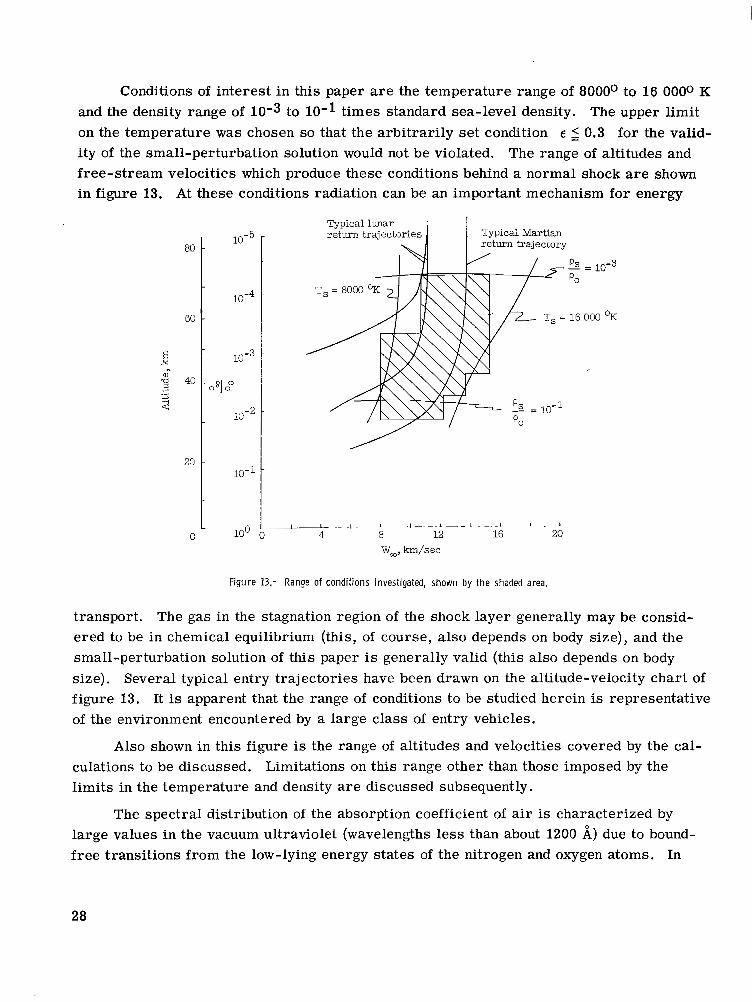
Conditions of interest in this paper are the temperature range of 8000° to 16 0000 K and the density range of 10-3 to 10-1 times standard sea-level density. The upper limit on the temperature was chosen so that the arbitrarily set condition E 2 0.3 for the valid- ity of the small-perturbation solution would not be violated. The range of altitudes and free-stream velocities which produce these conditions behind a normal shock are shown in figure 13. At these conditions radiation can be an important mechanism for energy
80
60
x E
% 40 a .A
3
20
0
Typical lunar return trajectories Typical Martian
I return trajectory
= 10-3
000 ?K
Wm, km/sec
Figure 13.- Range of conditions investigated, shown by the shaded area.
transport. The gas in the stagnation region of the shock layer generally may be consid- ered to be in chemical equilibrium (this, of course, also depends on body size), and the small-perturbation solution of this paper is generally valid (this also depends on body size). Several typical entry trajectories have been drawn on the altitude-velocity chart of f igure 13. It is apparent that the range of conditions to be studied herein is representative of the environment encountered by a large c lass of entry vehicles.
Also shown in this figure is the range of altitudes and velocities covered by the cal- culations to be discussed. Limitations on this range other than those imposed by the limits in the temperature and density are discussed subsequently.
The spectral distribution of the absorption coefficient of air is characterized by large values in the vacuum ultraviolet (wavelengths less than about 1200 A) due to bound- free transitions from the low-lying energy states of the nitrogen and oxygen atoms. In
28

addition, large values occur over small wavelength increments because of "line" or bound-bound transitions between excited states of the nitrogen and oxygen atoms. The strongest of these lines appear in the wavelength region between 900 and 1800 A. In other regions of the spectrum where the major contributions are due to bound-free transitions from excited states of the nitrogen and oxygen atoms, weak atomic lines, and free-free transitions produced by collisions between electrons and the ions of nitrogen and oxygen, the value of the absorption coefficient is not so large. ,
i , ' ,
2, -
10-9 I 1
~~ I I I 1 2 3 4 5 x 10³
0 Wavelmgth, A
Figure 14.- Step-function absorption-coefficient model. T = 14 0000 K; psp/po =
The step-function model used in this paper is composed of four high steps in the vacuum ultraviolet which correspond to the bound-free transitions from the three lowest energy levels of the nitrogen atom and the lowest level of the oxygen atom; a set of high, narrow, equally spaced steps of uniform height superimposed on a uniform background which corresponds to the bound-bound transitions in the ultraviolet; and a single low step which covers the rest of the spectrum. The values for the heights of the four vacuum- ultraviolet steps were determined by the method described in appendix B from the optical properties presented by Hahne in reference 9. The model for the ultraviolet bound-bound transitions was used because of the lack of detailed spectral information. Allen (ref. 10) presents the data on line contributions in the form of spectrally integrated radiation fluxes
29
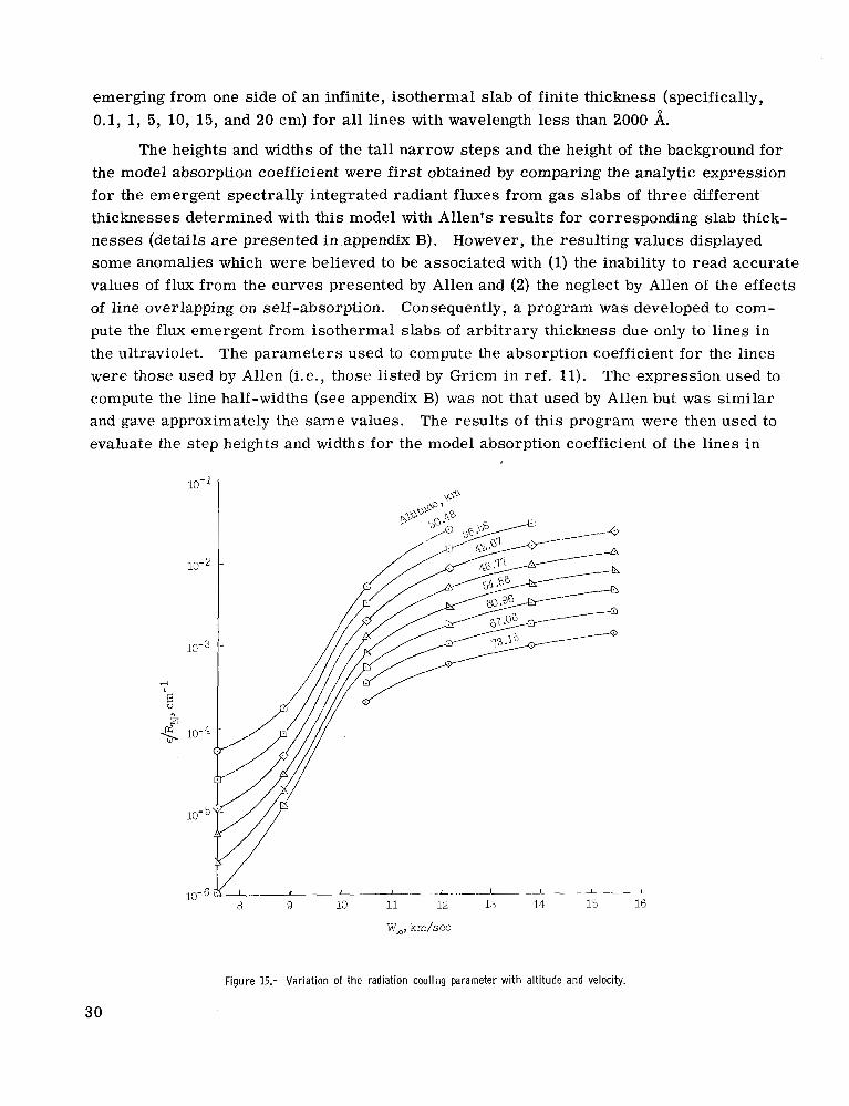
emerging from one side of an infinite, isothermal slab of finite thickness (specifically, 0.1, 1, 5, 10, 15, and 20 cm) for all lines with wavelength less than 2000 A.
The heights and widths of the tall narrow steps and the height of the background for the model absorption coefficient were first obtained by comparing the analytic expression for the emergent spectrally integrated radiant fluxes from gas slabs of three different thicknesses determined with this model with Allen's results for corresponding slab thick- nesses (details are presented in.appendix B). However, the resulting values displayed some anomalies which were believed to be associated with (1) the inability to read accurate values of f l u x from the curves presented by Allen and (2) the neglect by Allen of the effects of line overlapping on self-absorption. Consequently, a program was developed to com- pute the flux emergent from isothermal slabs of arbitrary thickness due only to lines in the ultraviolet. The parameters used to compute the absorption coefficient for the lines were those used by Allen (i.e., those listed by Griem in ref. 11). The expression used to compute the line half-widths (see appendix B) was not that used by Allen but was similar and gave approximately the same values. The results of this program were then used to evaluate the step heights and widths for the model absorption coefficient of the lines in
Figure 15.- Variation of the radiation cooling parameter with altitude and velocity.
30

TABLE I.- PARAMETERS FOR STEP-FUNCTION MODEL O F ABSORPTION COEFFICIENT
(a) Linear absorption coefficients for individual steps
[Final numbers l is ted with values of Pi represent powers of 10; for example, 5.001-1 signifies 5.001 X
1-13, cm-1
2.786-2 5.012-2
3.350-2 5.433-2
1.355-2 2.583-1 5.304-1 7.241-1 7.295-1 5.480-1
5.153+0 1.717+0
7.881+0 9.548+0 9.820+0
1-14, cm-1
8.360-1 2.464+0 1.601+0 9.039-1 4.229-1 3.165+0 3.029+0 2.853+0 2.502+0 1.923+0 4.628+0 7.941+0 1.050+1 1.189+1 1.189+1
1
i
1-1 57 Cm-1
3.475-3 8.511-3 1.132-2 8.091-3 3.681-3 3.214-2 8.913-2 1.475-1 1.702-1 1.417-1 2.123-1 8.553-1
2.192+0 1.590+0
2.477+0
1-1 69 cm-1
8.115-1 2.422+0 1.588+0 8.784-1 4.100-1 2.939+0 2.588+0 2.276+0 1.943+0 1.516+0 3.124+0 3.648+0 4.206+0 4.529+0 4.543+0
1-1 7, cm-1
3.404-5 ~~
2.443-4 5.470-4 6.152-4 3.945-4 2.570-4
3.236-3 1.242-3
6.546-3 5.483-3
1.148-3
~
5.888-3
2.594-2 1.507-2
3.412-2
1-19, cm-1
1-11, Cm-1
1-12, cm-1
- 1-17
cm-1 (t)
7.310-6
6.690-4 1.456-4
1.179-3 1.039-3
T, OK 'Sp/Pc
10 000 8 000
12 000 14 000 16 000 I 4.606-1 1.067-1
5.001-1 8.629-2
3.319-1
2.291-2 5.297-2
1.004-1 1.577-1 5.902-2
4.678+0 8.418-1 4.880+0
1.294+0 4.389+0 1.123+0
1.212+0 3.370+0 2.107+0 8.833-1
8 000 10-2 10 000 12 000 14 000 16 000 I 1.322-3
1.152-4
8.130-3 2.467-2 3.958-2 2.426-3 1.350-2 8.247-2 2.939-1 6.629-1
2.907+0 8.318-5 2.500+0
2.415-3 2.132+0 4.943-4
7.194-3 1.778+0 1.381+0 1.002-2
10 000 12 000 14 000 16 000 I 8 000 10-1
4.764+1 7.394+0 3.296+1 1.112+1
4.775+1 1.393+1 4.375+1 1.545+1 3.715+1 1.517+1
2.912+0 2.254-3 2.793+0
1.745-1 2.100+0 8.531-2 2.363+0 2.793-2 2.631+0 6.887-3
c .I
c
(b) In tegra ls of the nondimensional Planck function* across individual steps
[Final numbers listed with values of Bi represent powers of 10; for example, 1.140-6 signifies 1.140 x 10-61
B8 ! B3
3.006-4 1.841-5
1.702-3 5.358-3 1.180-2 1.841-5 2.992-4 1.690-3 5.297-3 1.167-2
2.958-4 1.837-5
1.629-3 4.920-3 1.038-2
B4
2.838-9 1.429-7
7.031-6 1.828-6
1.315-5 1.047-8 9.205-7 1.309-5 6.668-5 1.687-4 2.004-7 1.279-5
7.638-4 1.517-4
2.198-3
B5
7.014-5 7.943-4 3.524-3 9.290-3 1.795-2 7.015-5 7.925-4 3.499-3 9.183-3 1.770-2 6.998-5 7.816-4 3.373-3 8.551-3 1.578-2
B6
3.776-7 1.079-8
3.784-6 1.219-5 1.995-5 3.990-8 2.438-6 2.710-5 1.156-4 2.564-4
4.831-6 5.260-8
4.395-4 7.328-5
1.449-3
B7
9.506-3 3.811-2 8.730-2 1.471-1 2.055-1 9.506-3 3.802-2 8.690-2
2.028-1 9.484-3 3.750-2 8.375-2
1.455-1
1.352-1 1.806-1
8 000 10 000
14 000 12 000
16 000 8 000
10 000 12 000 14 000 16 000
10 000 8 000
12 000 14 000 16 000
"
4.123-5 6.077-5 1.140-6 2.554-6
4.133-4 4.410-4 2.018-3 1.654-3 6.342-3 4.153-3 1.140-6 2.554-6
4.133-4 4.410-4 4.123-5 6.077-5
2.018-3 1.654-3 6.342-3 4.153-3 1.140-6 2.554-6 4.123-5 6.077-5 4.133-4 4.410-4 2.018-3 1.654-3 6.342-3 4.153-3
5.408-6
6.730-4 1.170-4
1.828-3 2.931-3
6.138-4 2.716-5
3.767-3 1.208-2 2.518-2
~
9.901-1 ' 9.605-1 9.064-1
~ 8.343-1
9.605-1 9.064-1 8.343-1 7.540-1
* 852 B1 = s,,, BX
B4 = (1 - BX dX 1020
911
B7 = p11800 BA d l 1130
B8 = (1 - BX dX 1800
1130 Bg =
.11800 BX dX
31

I".. 1 I . . I. .. _1 1 ." - 1
8 9 10 11 12 13 14 1'3 16
W,, km/sec
Figure 16.- Variation of the Bouguer number with altitude and velocity.
the ultraviolet. This model should give a reasonable estimate of the effects of absorp- tion, provided that the values of slab thickness chosen do not differ greatly from the shock standoff distance and that the temperature distribution in the shock layer does not differ much from isothermal.
The maximum monochromatic absorption coefficient at wavelengths greater than 1800 is small enough to insure that the maximum monochromatic optical thickness of a shock layer will be very much less than 1 for the temperatures, densities, and shock standoff distances of interest. Consequently, the contributions of the various radiators can be legitimately accounted for with a Planck type of average absorption coefficient for the wavelength interval of 1800 to 100 000 A.
An example of the model absorption coefficient is shown in figure 14. A compila- tion of all the model absorption-coefficient parameters is presented in table I.
The absorption-coefficient model was used to compute E/RN, the radiation cooling parameter per centimeter of nose radius, and kp/RN, the Bouguer number per centi- meter of nose radius, for a range of altitudes and velocities. The results are presented in figures 15 and 16.
32
Nongray-Gas Results
The nongray absorption-coefficient model developed herein was used in conjunction with the small-perturbation method to obtain stagnation-point solutions over the range of conditions indicated in figure 13. This range of conditions was limited by the tempera- ture and density range of the absorption-coefficient model. It was also restricted by excluding the high-altitude, low-velocity regime because of large values of the enthalpy variation of the Planck mean absorption coefficient at normal-shock conditions, which can lead to inaccuracy in the small-perturbation solution. (Fortunately, this is a range in which radiation is not particularly important, anyway.) Finally, it was restricted to velocities less than or equal to 15.24 km/sec (50 000 ft/sec) because the radiation cooling parameter would exceed 0.3 (the arbitrary upper limit for validity of the present method) at higher velocities, except for rather small nose radii for which the assumptions of thermodynamic and chemical equilibrium become suspect.
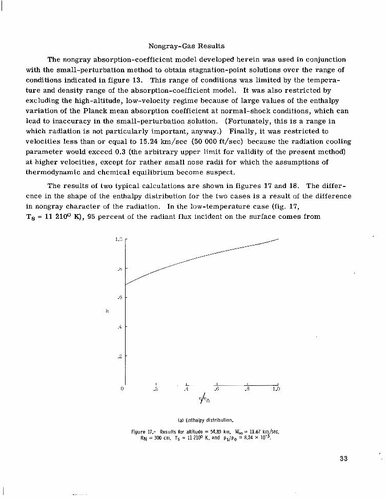
The results of two typical calculations are shown in figures 17 and 18. The differ- ence in the shape of the enthalpy distribution for the two cases is a result of the difference in nongray character of the radiation. In the low-temperature case (fig. 17, Ts = 11 210° K), 95 percent of the radiant flux incident on the surface comes from
1.0
.8
.6
h
.4
.2
0 I I I I I
.2 .4 .6 .8 1.0
(a) Enthalpy distribution.
Figure 17.- Results for altitude = 54.85 krn, W,= 11.67 krn/sec, RN = 300 cm, TS = 11 2100 K, and ps/po = 8.24 x 10⁻³.
33

optically thin portions of the spectrum. As a result the enthalpy distribution is s imilar to those for optically thin gray gases (see, for example, the curves for k p = 0 and 0.3 in fig. 5(c)). However, at the higher temperature (fig. 18, Ts = 14 021° K) only 45 per- cent of the radiation f l u x incident on the surface comes from optically thin portions of the spectrum. As a result the enthalpy distribution appears more like those for a gray gas with Bouguer number of order 1 (see curves for kp = 1.0 and 3.0 in fig. 5(c)).
Spectral distributions of the radiant flux incident on the body surface are presented in figures 17(b) and 18(b) for the two cases. These distributions are, of course, based on the step-function model and do not accurately represent the detailed spectra for air. Radiation from the lines in the vacuum ultraviolet (X 2 2000 A) is represented
1 2 3 0
Wavelength, A
4 5 x 10³
(b) Spectral distribution of radiant flux incident on the body surface.
Figure 17.- Concluded.
34

schematically, as the absorption-coefficient model does not specify the number, locations, o r widths of the individual lines. Despite these inadequacies the spectral distributions provide some physical understanding of the nature of radiant energy transport in a non- gray, nonisothermal slab of gas. For example, the flux in the optically thick portions of the spectrum originates in the cooler regions of the shock layer adjacent to the body sur - face and is characterized by the temperature in these cooler regions. The f l u x in the optically thin portions of the spectrum comes from the entire shock layer and is charac- terized by its average temperature.
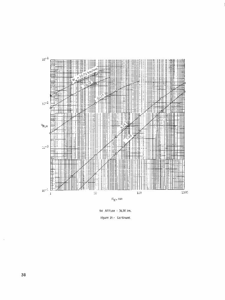
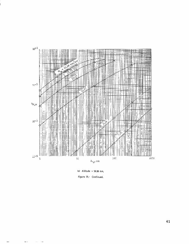
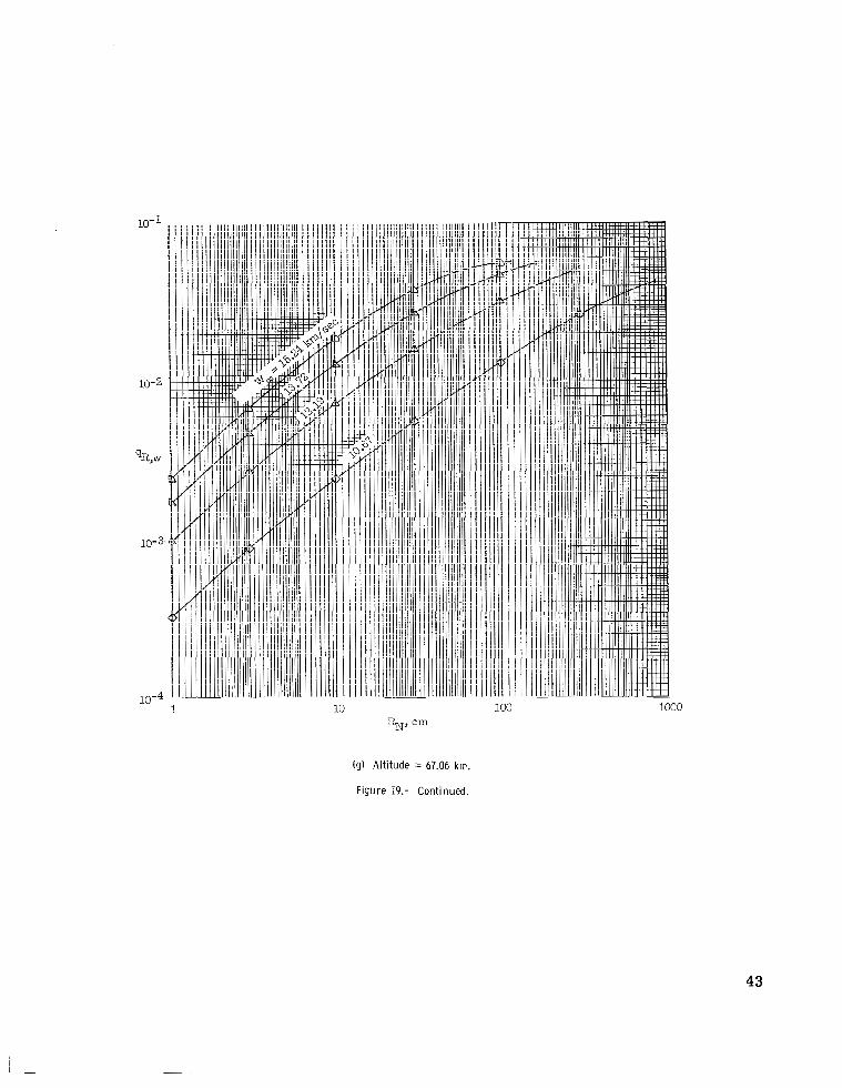
The variation with free-stream velocity, altitude, and body nose radius of the non- dimensional rate of radiant heat transfer to a nonreflecting stagnation surface is presented in f igure 19. It can be seen that the radiant heat-transfer rate varies linearly with nose radius only for very small values of the heating rate. At higher heating levels the radi- ant heat-transfer rate increases more slowly with nose radius. If the nose radius were allowed to increase indefinitely, while altitude and velocity remained fixed, the radiant heat-transfer rate would reach a maximum and then decrease asymptotically toward zero. This type of behavior has been demonstrated by the gray-gas analyses of references 2 and 12.
0
(a) Enthalpy distribution.
Figure 18.- Results for altitude = 67.10 km, W,= 15.24 km/sec, RN = 30 cm, TS = 14 02lo K, and ps/po = 2.135 X 10⁻³.
35

Because the radiative properties of high-temperature air are usually presented in the form of global (wavelength-integrated) fluxes emerging from one side of an isothermal slab of finite thickness, it is desirable to define a radiation cooling factor. This factor Fc is the ratio of qR,w, the radiant heat-transfer rate for a self-absorbing nonisother-
mal shock layer, to the heat-transfer rate for a self-absorbing isothermal, o r adiabatic, shock layer. The influence of self-absorption nearly cancels in this ratio so that Fc depends primarily on the fraction of energy lost by radiation from an isothermal shock layer and the enthalpy dependence of the absorption coefficient. The fraction of energy lost by radiation from an isothermal shock layer is proportional to q the nondi- mensional global flux emerging from one side of an isothermal slab with thickness equal to the shock standoff distance.
R,w,a’
5 x 10 3 1 2 3
Wavelength, A 0
4
( b ) Spectral distribution of radiant flux incident on the body surface.
Figure 18.- Concluded.
36

'0 1000
(a) Altitude = 30.48 km.
Figure 19.- Variation of the stagnation-point radiant heat-transfer rate with altitude, velocity, and nose radius.
37
10-
10-2
10-3
10- 1 1000
IbJ Altitude = 36.58 km.
Figure 19.- Continued.
38

100 1000
( c ) Altitude = 42.67 km.
Figure 19.- Continued.
39

10- 1
10-2
qR,w
10-3
10-4 1 10 1000
(dl Altitude = 48.77 krn.
Figure 19.- Continued.
40
10-
10-4 1 10 100 1000
(e) Altitude = 54.86 km.
Figure 19.- Continued.
41

10- 1
10- 2
10- 3
10-4 10 100 1000
I f ) Altitude = 60.96 krn.
Figure 19.- Continued.
4 2
10- 1
10- 2
10- 3
10 1000
(g) Altitude = 67.06 km.
Figure 19.- Continued.
43

I
10- 1
10-2
qR,w
10-3
10- 4 1
( h ) Altitude = 73.15 km.
Figure 19.- Concluded.
44

Since the absorp'.ion-coefficient model does not vary drastically over the range of conditions of interest , ti. enthalpy dependence of the absorption coefficient can be char- acterized by (though certainly not specified by) the enthalpy dependence of the Planck mean absorption coefficient at normal-shock equilibrium conditions (dKpl dh) h=l. This
quantity was found to be relatively constant over the range of altitudes for a given velocity except at 7.92 and 9.14 km/sec. (A plot of (dKp/dh) against velocity for various
altitudes is presented in fig. 20. h= 1
) Because velocity is a more convenient quantity than dK dh , the cooling fac- ( p/ ) h = l
t o r s are shown as plots of Fc against q for various velocities (fig. 21). It can
be seen that the results correlate well on this basis except for the two lowest velocities, 7.92 and 9.14 km/sec. The results from two other nongray studies (refs. 3 and 13), which neglected line radiation, are indicated in these plots by solid symbols. In two cases it
R,w,a
8
h
0
0
0 n 8
Altitude, km
0 30.48 0 36.58 0 42.67 A 48.'17 L1 54.86 b 60.96
0 73.15 n 67.06
Figure 20.- The enthalpy variation of the absorption coefficient as a function of altitude and velocity.
45
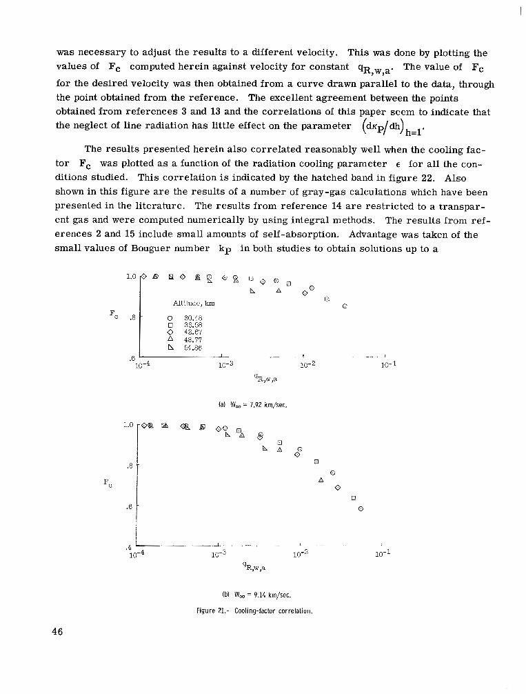
was necessary to adjust the results to a different velocity. This was done by plotting the values of Fc computed herein against velocity for constant q R,w,a' The value of Fc
for the desired velocity was then obtained from a curve drawn parallel to the data, through the point obtained from the reference. The excellent agreement between the points obtained from references 3 and 13 and the correlations of this paper seem to indicate that the neglect of line radiation has little effect on the parameter (dKp/dh)h=l.
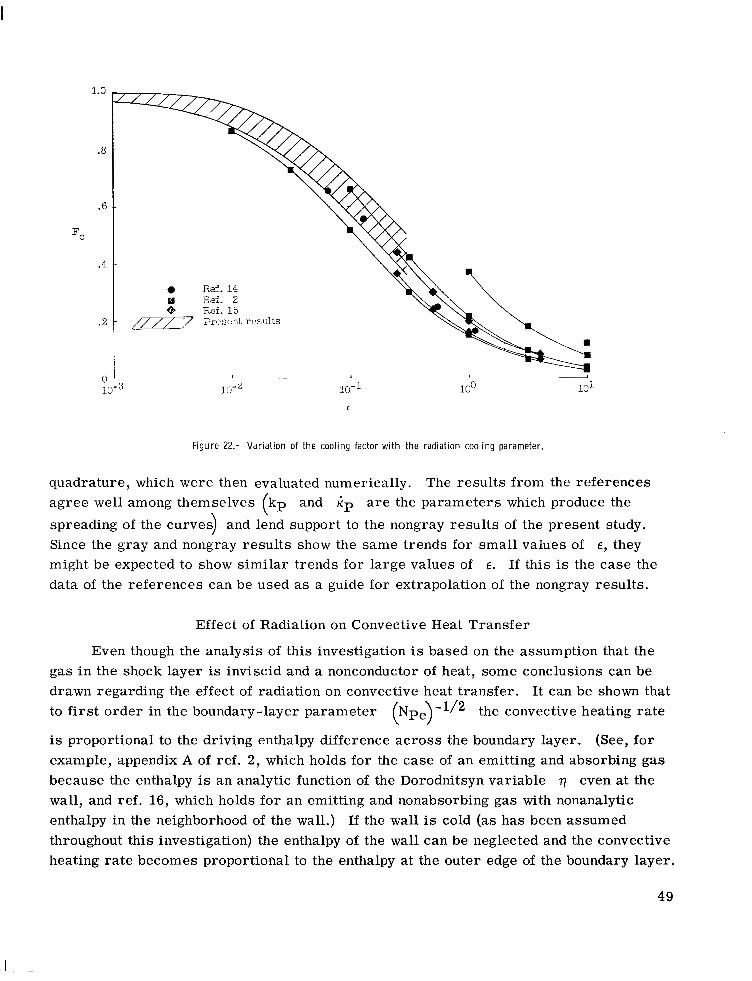
The results presented herein also correlated reasonably well when the cooling fac- tor Fc was plotted as a function of the radiation cooling parameter E fo r all the con- ditions studied. This correlation is indicated by the hatched band in figure 22. Also shown in this f igure are the results of a number of gray-gas calculations which have been presented in the literature. The results from reference 14 are res t r ic ted to a transpar- ent gas and were computed numerically by using integral methods. The results from ref- erences 2 and 15 include small amounts of self-absorption. Advantage was taken of the small values of Bouguer number kp in both studies to obtain solutions up to a
(a) W, = 7.92 km/sec.
*8 t .6
8 h
0 A
a
A 0
0 a
0
I
(b) W, = 9.14 km/sec.
Figure 21.- Cooling-factor correlation.
46
1.0 -
.8
F, .6
.4
Altitude, km
0 30.48 0 36.58 0 42.67 A 48.77 h 54.86
0 67.06 0 73.15
n 60.96
8
r3
0 0 n
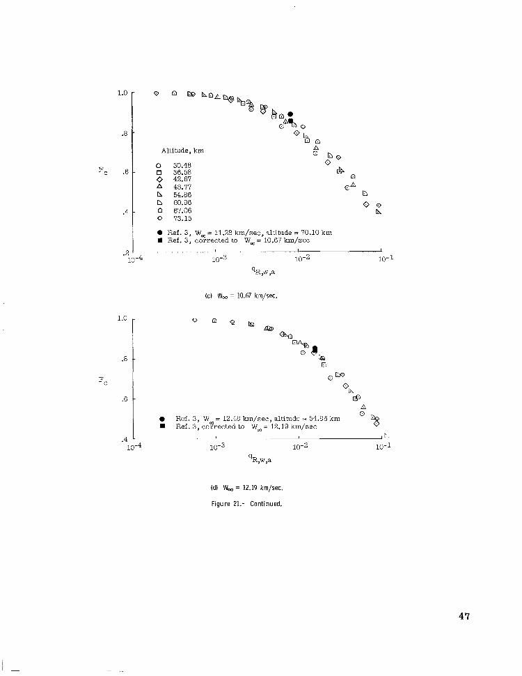
I 0 Ref. 3, W, = 11.28 km/sec, altitude = 70.10 km W Ref. 3, corrected to W, = 10.67 km/sec
.2 - I I 1 . . . . . . .
10-4 " . ~
10-3 10-2 10-1 qR,w ,a
(c) W, = 10.67 km/sec.
1.0 -
.8 -
Fc
.6 - a
I A 0 R e f . 3, W = 12.48 km/sec, altitude = 54.86 km 0 %
Ref. 3, coyrected to W, = 12.19 km/sec
.4 * ! ! 1 k. 10-3 10-2 10-1
9 R,w,a
(dl W, = 12.19 km/sec.
Figure 21.- Continued.
47

1.0 -
.8 -
Fc .6 -
.4 -
Altitude, km
0 36.58 0 42.67 A 48.77 b 54.86 0 60.96
.2 . . . 1
10-4 10-3 ~. .
10-2
qR,w ,a
- . 1
10-1
(e) W, = 13.72 km/sec.
I . I
10-4 10-3 10-2 10-1 ‘R,w ,a
(f) W, = 15.24 km/sec.
Figure 21.- Concluded.
48
I
1.0
.a
.6
Fc
.4
I 0 R e f . 14 a Ref. 2
.2
n " 10-3 lu-2 10-1 100
E
Figure 22.- Variation of the cooling factor with the radiation cooling parameter
quadrature, which were then evaluated numerically. The results from the references agree well among themselves kp and KP are the parameters which produce the spreading of the curves) and lend support to the nongray results of the present study. Since the gray and nongray results show the same trends for small values of E , they might be expected to show similar trends for large values of E. If this is the case the data of the references can be used as a guide for extrapolation of the nongray results.
(
Effect of Radiation on Convective Heat Transfer
Even though the analysis of this investigation is based on the assumption that the gas in the shock layer is inviscid and a nonconductor of heat, some conclusions can be drawn regarding the effect of radiation on convective heat transfer. It can be shown that to first order in the boundary-layer parameter (Npe)-l12 the convective heating rate
is proportional to the driving enthalpy difference across the boundary layer. (See, for example, appendix A of ref. 2, which holds for the case of an emitting and absorbing gas because the enthalpy is an analytic function of the Dorodnitsyn variable even at the wall, and ref. 16, which holds for an emitting and nonabsorbing gas with nonanalytic enthalpy in the neighborhood of the wall.) If the wall is cold (as has been assumed throughout this investigation) the enthalpy of the wall can be neglected and the convective heating rate becomes proportional to the enthalpy at the outer edge of the boundary layer.
49

The location of the outer edge depends on the boundary-layer parameter and is given approximately by
Values of the enthalpy he at the edge of the heat-conducting boundary layer were obtained for the range of altitudes, velocities, and nose radii for values of the P6clet num- ber Npe of lo2, 103, and lo4. The results are presented in f igure 23 as a function of the nondimensional adiabatic radiant heating rate for various velocities. A good correla- tion is obtained for he for the same reasons that a good correlation was obtained for the cooling factor.
The quantity he is an approximation to the ratio of convective heating rate for a radiating shock layer to that for a nonradiating shock layer. When radiant energy
.6 ~ I . I 1 - 1
10-3 10-2 10-1 qR,w ,a
(a) W, = 7.92 km/sec.
0
0 I I
10-2 10-1
(b) W, = 9.14 krn/sec.
Figure 23.- Correlation of the boundary-layer edge enthalpy.
50

transport is important: the convective heating is reduced from the radiationless value (he = 1). If the analysis could be continued to indefinitely large values of the nondimen- sional adiabatic radiant-heating rate, the value of he would become asymptotic to zero. This variation has been indicated by the gray-gas analyses of references 2, 12, and 17.
Of course, figure 23 gives only an order-of-magnitude estimate of the radiation- convection coupling. Not included are the effects of variable transport properties, enthalpy gradients at the edge of the boundary layer (a second-order effect), and differ- ences in the characteristic Reynolds and Prandtl numbers between radiating and nonradi- ating cases. Also no account has been taken of radiation in the boundary layer. In the cool region of the boundary layer near the wall the gas will absorb more radiant energy than it will emit. This will tend to increase the slope of the enthalpy distribution adjacent to the wall, which, in turn, will increase the convective heat transfer somewhat.
While absorption in the boundary layer will increase the stagnation-point convective heating rate it need not increase the stagnation-point total heating rate. It is apparent that a radiating gas in the boundary layer will (1) reduce the rate of radiant heat transfer
1 o 104
(c) W, = 10.67 krn/sec.
1.0 -
.8 -
he
.6 -
.4
0
I 1 1 . .
10-1
qR,w ,a
(d) W, = 12.19 km/sec.
Figure 23.- Continued.
51
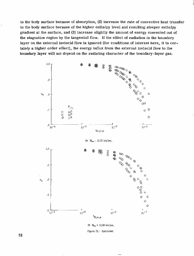
to the body surface because of absorption, (2) increase the ra te of convective heat transfer to the body surface because of the higher enthalpy level and resulting steeper enthalpy gradient at the surface, and (3) increase slightly the amount of energy convected out of the stagnation region by the tangential flow. If the effect of radiation in the boundary layer on the external inviscid flow is ignored (for conditions of interest here , it is ce r - tainly a higher order effect), the energy influx from the external inviscid flow to the boundary layer will not depend on the radiating character of the boundary-layer gas.
1.0
.a
he .6
1.0 e
.a -
he .6 -
.4 -
I I
10-3 10-2 qR ,w ,a
(e) W, = 13.72 krn/sec.
0
I
10-1
.2 1
10-2 'R,w,a
10-1
(f) W, = 15.24 km/sec.
Figure 23.- Concluded. 52

Whether o r not !!le increase in convective heating will be offset by the decrease in radiant heating depends . a large extent on the surface properties of the body. If the body surface were perfectly reflecting, the total heating rate to the surface would be increased by absorption in the boundary layer because only the convective component con- tributes to the total heating rate. If, on the other hand, the wall were perfectly absorbing, then consideration of an energy balance across the boundary layer would show that the total heat transferred to the surface by radiation and convection will be less for an absorbing boundary layer thanfor a nonabsorbing boundary layer because of the slightly ,
larger amount of energy convected out of the stagnation region by the tangential flowin the former case.
- ~ -
-~ ."
_I
.~ - __"
" ._ " - - - " -
For gases, most of the absorption by the boundary layer would occur in the vacuum- ultraviolet portion of the spectrum where, for most materials, the surface reflectivity is small. Thus, one might expect that the combined radiation and convection heat transfer to the surface as predicted by the inviscid radiating analysis and the nonradiating- boundary-layer analysis would be in reasonable agreement with, o r perhaps slightly higher than, what would be predicted from solutions of a radiating boundary layer properly matched to the external inviscid solution.
Radiation Blockage Effect of Ablated Vapor Layer
When the radiant heat-transfer rates are large the ablated vapor layer will absorb __
more radiant energy than it emits because the characteristic shock-layer temperature will be considerably higher than the characteristic ablated-vapor-layer temperature. If this 1s the case, the hot-airshock layer can be solved independently of the ablated vapor " . . ~-
layer (such as has been done in this study) and the results can be used to establish bound- a ry conditions at the outer edge of the ablated vapor layer. Solution of the ablated-vapor- layer problem is complicated by the importance of viscosity, thermal conductivity, species diffusion, and chemical reactions, and no attempt has been made to obtain a solution here. However, it has been pointed out that the ablated vapor layer will act to inhibit the trans- f e r of radiant energy from the hot-air shock layer to the body surface. Since this is a beneficial effect, it is advisable (strictly from the point of view of r e d u c h t h e r a d i a n t heat-transfer rate) to provide for an ablated vapor with large and extensive (in wavelength) absorption cross sections s u c k s t h o z o f the alkali metals (lithium, sodium, and potassium).
" - ." -
- ~ " . _"
.- - - " ~
" "- F c_ " ~- "
_- ~ -
-%
Precursor Effect
Some of the radiation energy emerging from the front of the shock layer is absorbed by the cold free-stream air in the path of the vehicle. Much of this absorbed energy ionizes nitrogen and oxygen molecules and dissociates oxygen molecules (some of the
53

resulting oxygen atoms may in turn be ionized by the strong vacuum-ultraviolet radiation). Because of the low density of the free-stream air it seems likely that the number of ions and electrons carried into the shock layer would be considerably larger than would be predicted for thermodynamic and chemical equilibrium. For the same reason it would be likely that the heavy particles (molecules, atoms, and ions) entering the shock layer would have very little thermal energy (characterized by a temperature not much in excess of the ambient temperature), while the electrons would carry more thermal energy (character- ized by a somewhat elevated electron temperature). The energy absorbed in the free s t ream would only slightly affect the density and velocity. Thus the energy absorbed in the path of the vehicle is returned to the shock layer largely in the form of chemical energy and thermal energy of electrons. Under the assumption of local thermodynamic and chemical equilibrium within the shock layer, the return of this energy will result in a value of enthalpy behind the shock larger than that predicted for no free-stream absorp- tion. It should be noted that the presence of electrons (even trace amounts) in the free stream will speed up the ionization processes behind the shock and increase the range of validity of the assumption of equilibrium in the shock layer.
The momentum and energy balances across the shock wave are
1 2 2 P s = - P,W,
where ps is the pressure immediately behind the shock, hs* is the enthalpy immedi- ately behind the shock when absorption by the f ree s t ream is taken into account, qR,$ is the nondimensional radiant energy f l u x emerging from the shock layer in the upstream direction, and y is the fraction of this flux which is absorbed by the cold free-stream air and returned to the shock layer. The energy balance was obtained under the reason- able assumption that the free-stream air absorbs but does not emit radiant energy. The dominant effect of absorption by the f ree s t ream is an increase in shock-layer enthalpy, with no change in shock-layer pressure. Therefore the effect on the radiant and convec- tive stagnation-point heating rates can be estimated from results that do not include free- stream absorption by using an effective free-stream velocity W,* and an effective free- stream density p,* :
2 P,* E P,($)
54

When qR,s is small , as it must be in the small-perturbation analysis, it can be con-
servatively approximated by q R,w,a7 the adiabatic heating rate. Also because of the
smallness of q expressions (41) become r,w,a7
If W, - W, and p, - p, are small compared with W, and p,, respectively, * * the rate of radiant heat transfer to the stagnation point with free-stream absorption becomes
By combining equations (42) and (43) and ignoring terms of order (yqR,w,a) or higher,
a factor for the increase of radiant heat-transfer rate with free-stream absorption can be defined. This factor is
This factor with y
radii considered in = 1 has been computed for the range of altitudes, velocities, and nose this study, and the results are presented as functions of q for
R,w,a various velocities in figure 24. These values of +R represent upper bounds because y
will be less than 1. The determination of y is complicated by nonequilibrium thermo- dynamics and chemistry in the absorbing free stream and has not been attempted herein. Values of GR for y different from 1 can be obtained from the plots of figure 24 by means of the formula
55
I
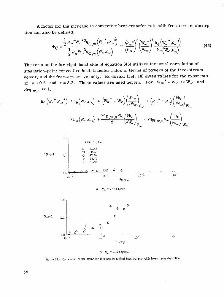
A factor for the increase in convective heat-transfer rate with free-stream absorp- tion can also be defined:
The term on the far right-hand side of equation (46) utilizes the usual correlation of stagnation-point convective heat-transfer rates in t e rms of powers of the free-stream density and the free-stream velocity. Hoshizaki (ref. 18) gives values for the exponents of s = 0.5 and t = 3.2. These values are used herein. For W,* - W, << W, and
yqR,w,a << 1,
Altitude, km
0 30.48 0 36.58 0 42.67
n 54.86 A 48.77
(a) W, = 7.92 km/sec.
56

1.5
1.4
1.3
1.2
1.1
1.0
1.3
1.2
1.1
Altitude, km
0 30.48 0 36.58 0 42.67
h 54.86 b 60.96
0 73.15 0 67.06
a 48.77
0 , n
10-3 10-2
1.0 1. 10-3
10-1 100 9R ,w ,a
(c) W, = 10.67 km/sec.
(dl W, = 12.19 km/sec.
Figure 24.- Continued.
57

Thus
J
On physical grounds it can be argued that he will not increase with W, and that
- W, he will not decrease with W,. The results of this investigation substantiate this 1 2 2 argument except for some cases where q is large and the expected precision for
he is poor. Thus the first derivative in formula (47) is bounded as follows: R,w,a
1.3 -
'R,~,r,l 1.2 -
1.1
Altitude, km
0 42.67 0 36.58
A 48.77
b 60.96
0 73.15
tl 54.86
n 67.06
(e) W, = 13.72 km/sec.
1.3
1.2
@R,r,l
1.1
Q
A
(f) W, = 15.24 km/sec.
Figure 24.- Concluded.
58

W, = 15.24 km/sec Alt. = 60.96 km R, = 30 cm
0 8 0
10.67 km/sec 54.86 km
300 cm
/ . I
100
I 10-2 10-1
‘R ,w ,a
Figure 25.- Bounding curves of the factor for increase i n convective heating with free-stream absorption.
Examination of the results indicates that the other derivative is bounded as follows:
Consequently, the factor +c is also bounded:
The two limit curves for Qrc are shown as functions of yq in figure 25. Also
shown are values.of @c obtained in this study for y = 0.25, 0.50, and 1.00 for two d i f - ferent combinations of free-stream velocity, altitude, and nose radius.
R,w,a
Body Surface Reflectivity
In the nongray studies the surface has been assumed to be a perfect absorber. This is a conservative assumption which was necessitated by the lack of reliable information concerning the radiative properties of high-temperature ablating materials. It is quite likely that a real surface will be partially reflecting in the visible and infrared portions of
59

I I II I I I
the spectrum. The small-perturbation method presented in this paper can easily be modified to account for nongray surface properties by introducing a step function (in wave- length) model for the surface reflectivity. It is advantageous to specify the steps so that the edges coincide (in wavelength) with the edges of the step-function absorption- coefficient model.
From the point of view of reducing radiant heat transfer to the body surface, a highly reflecting surface would be desirable. If the blockage effect of the ablated vapor is considered in addition to the radiative surface properties, it is apparent that an attrac- tive ablation material would be one which in the vapor form absorbs strongly in certain spectral regions (such as the vacuum ultraviolet), and in the solid, o r liquid, form reflects strongly in the remainder of the spectrum. Whether o r not a mater ia l exis ts which exhib- its a definite advantage over others is not now known.
RESUME
A singular perturbation solution to the blunt-body stagnation flow of an inviscid, radiating gas has been obtained by means of the P-L-K, or perturbation-of-coordinates, method. A number of resul ts for a gray gas have been presented in order to provide some physical insight into the effects of various parameters on the shock-layer enthalpy profiles and the radiant heat-transfer rates.
A nongray absorption-coefficient model was developed which includes, in an approx- imate way, the important vacuum-ultraviolet contributions of bound-free and line transi- tions. This model was used to obtain solutions pertinent to the case of reentry into the earth's atmosphere. While the resul ts are res t r ic ted to small values of the radiation cooling parameter, which characterizes the relative importance of radiation and convec- tion as energy-transport mechanisms, they cover broad ranges of vehicle velocity, alti- tude, and nose radius, which a r e of practical interest.
The characteristic enthalpy variation of the model absorption coefficient was found to be nearly independent of altitude and nose radius for fixed vehicle velocity except for velocities lower than 10.67 km/sec. Thus it was possible to correlate certain quantities by plotting these quantities as functions of the nondimensional adiabatic radiant heat- t ransfer rate for various altitudes and nose radii at fixed vehicle velocity. Among the quantities correlated was the cooling factor (the ratio of the stagnation-point radiant heat-transfer rate to the adiabatic radiant heat-transfer rate). The cooling-factor corre- lation is particularly useful because it eliminates the need to perform nonadiabatic cal- culations whenever radiant heat-transfer rates are des i red . Also correlated was the factor by which the convective heat-transfer rate is reduced because of radiation losses
60

in the shock layer. Finally, upper bound estimates were made of the effects of absorption of precursor radiation by the free-stream air on the radiant and convective heat-transfer ra tes .
Langley Research Center, National Aeronautics and Space Administration,
Langley Station, Hampton, Va., May 24, 1968, 129-01-02-03-23.
61

APPENDIX A
MATHEMATICAL DEVELOPMENT
In this appendix, the method of small perturbation will be used to obtain a solution to the integrodifferential system of equations governing the flow in the inviscid region of a radiating shock layer. Mathematical details that are not considered to be appropriate to the body of the paper are included herein.
The system of equations to be treated is presented below:
f(0) = 0
Conventional Perturbation Procedure
If the functions h(q,E) and f(q7E) are assumed to be analytic in the vicinity of E = 0, they may be written in the expanded form:
P 03
It is anticipated that the first few t e rms of these expansions will provide an accurate estimate to the solution of the system of equations (Al) to (A6) when the parameter E is small compared with 1.
62

APPENDIX A
The integral term qR' and the constant qA also depend on the parameter E
through their dependence on the function h(q,E). These quantities are also assumed to be analytic functions of E near E = 0, so that
n= 1
Substituting the expansions (A?) to (A10) into system (Al) to (A6) yields
k o f o " - (fo ')2 + a2h,] + €@r,fl" - 2f0'fl' + 2fo"fl + a2hl 1 - 2fO1f2f1 + 2fOV?f2 + 2flfl" - ( f ~ ' ) ~ + a 2 h d + . . . = 0
C I M [ I fo(0) + E f l (0) + €2 f2(0) + . . . = 0

APPENDIX A
Since the small parameter E is arbitrary, system (All) to (A16) can be satisfied only if each coefficient of each expansion in E is identically zero. This leads to a recursive set of purely differential systems.
The zero-order system is
ho' = 0
hOFA,O) =
fo(0) = 0
fo(llA,O) =
The solutions to this system are easily found. They a r e
ho = 1
The systems of first and second order may be written in the general form
64

APPENDIX A
fn'(llA,o) = Qn
Equation (A26) can be integrated directly to obtain
the homogeneous solutions of equation (A27) are q + a and 72. As shown by
Ince (ref. 19), the complete solution is 2(1 - a)
Substituting this expression into condition (A31) provides the following relation for the determination of qA,n:
The quantities Gn(q), @n, On, and qn a r e
@2(q) = - f l f l ' ' + i(fl')2 - 1. a2h2(q) 2 2

APPENDIX A
1 cpl(X)dx - a)qA,l + (2 - a)Jo VA,l - 2(1 - a)77A,2 (-442)
[(I - a)x + a]
The divergence of the radiant f l u x vector qR'(q) may be written in expanded form
by substitution of (A7) to (A10) and the expansions of the quantities Kh(h), BX(h), T ~ ( ~ , E ) , and En[7X(q,Eq into expression (7) of the body of the paper. For completeness the expanded forms of K ~ , Bx, T ~ , and En(7X> are given here:
BX(h) = Bx(1) + EBh(l)hl(q) + r2F,(l)h2(q) + + Bk(l)h12(rl)l + . . . (A441
1
0 = ~ ~ ( l ) q + ~ k ~ ( l ) l hl(q)dq + . . . (A4 5)
66
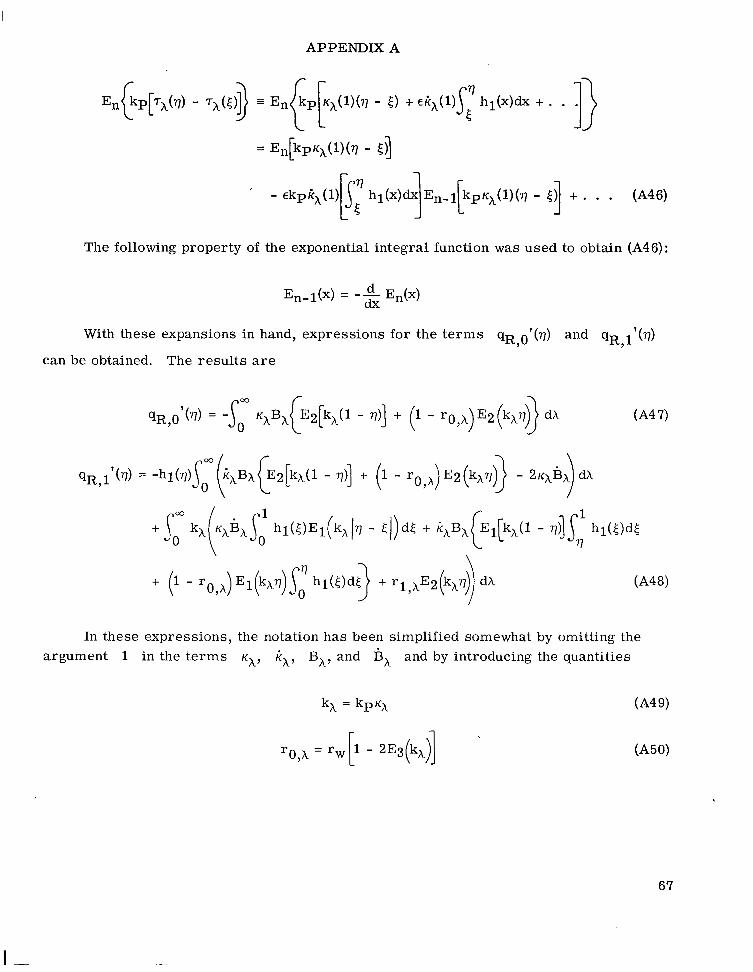
APPENDIX A
The following property of the exponential integral function was used to obtain (A46):
With these expansions in hand, expressions for the terms qR,O1(q) and qR ll(q) 7
can be obtained. The results are
In these expressions, the notation has been simplified somewhat by omitting the argument 1 in the terms K ~ , kX7 BA, and B X and by introducing the quantities
67
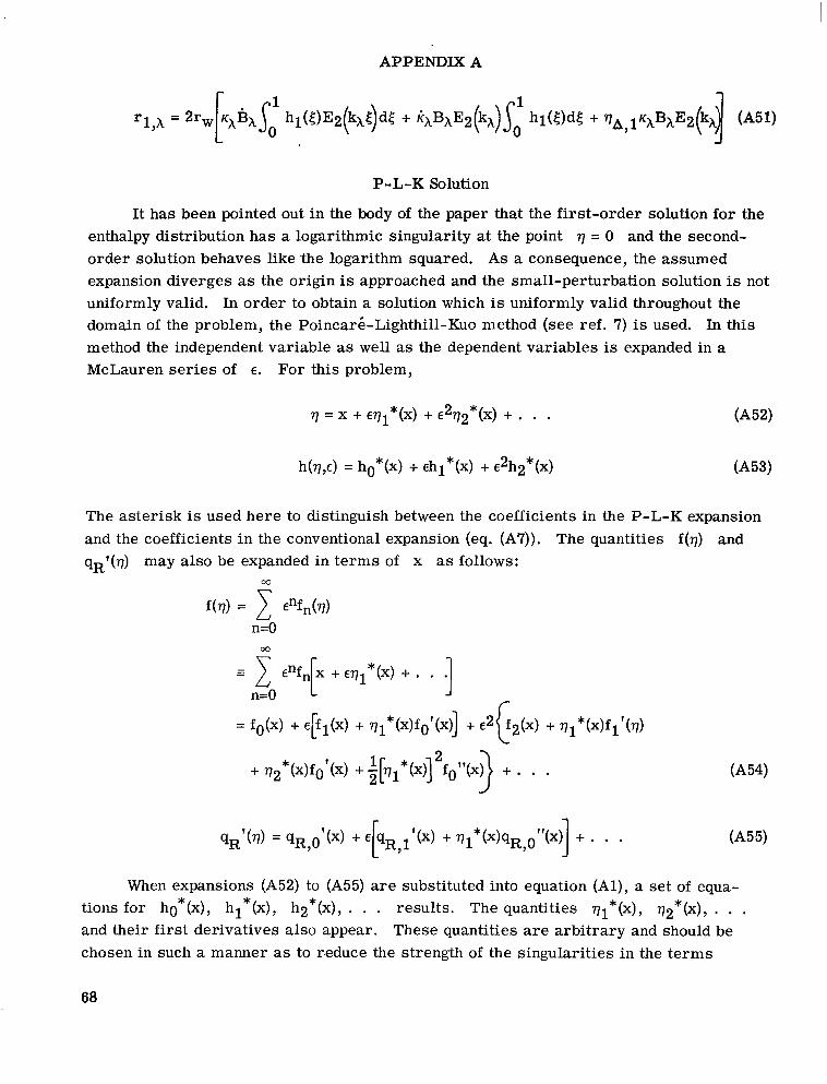
APPENDIX A
P-L-K Solution
It has been pointed out in the body of the paper that the first-order solution for the enthalpy distribution has a logarithmic singularity at the point q = 0 and the second- order solution behaves like 'the logarithm squared. As a consequence, the assumed expansion diverges as the origin is approached and the small-perturbation solution is not uniformly valid. In order to obtain a solution which is uniformly valid throughout the domain of the problem, the Poincarg-Lighthill-Kuo method (see ref. 7) is used. In this method the independent variable as well as the dependent variables is expanded in a McLauren series of E . For this problem,
h(q,E) = ho*(X) + Ehl*(X) + e2h2*(x) (A531
The asterisk is used here to distinguish between the coefficients in the P-L-K expansion and the coefficients in the conventional expansion (eq. (A7)). The quantities f(q) and qRf(q) may also be expanded in terms of x as follows:
00 P
00
When expansions (A52) to (A55) are substituted into equation (Al), a set of equa- tions for ho*(x), hl*(x), h2*(x), . . . results. The quantities ql*(x), q2*(x), . . . and their first derivatives also appear. These quantit ies are arbitrary and should be chosen in such a manner as to r.educe the strength of the singularit ies in the terms
68

APPENDIX A
h2*(x), h3*(x), . . ., s' that these singularities are never stronger than that of the low- est order singular term ; .. the present case, the f irst-order term). Pritulo (ref. 8) has shown that the coefficients in the expansion of h(q,E) in the P-L-K method are related to the coefficients of the conventional expansion in the following manner:
Now, instead of choosing differential equations for the qn*(x) to satisfy the criterion previously stated, the values of the qn*(x) can be chosen directly. In this case, an obvious choice is simply
which gives h2*(x) = 0. (This choice satisfies the condition q1*(1) = q
Transforming the independent variable by means of formula (A52) removes the sin- gularity from the domain of the problem. That this is true can be seen by noting that the condition q = 0 does not imply x = 0 but rather (for this problem) implies that x is some small positive number. Hence, to first order, h(q,e) = 1 + ehl*(q) is nonsingular in the domain 0 S q 9 1.
Method of Matched Asymptotic Expansions
V&n Dyke has pointed out (ref. 20) that the method of matched asymptotic expansions is applicable whenever the P-L-K method can be used. Thus, it would be interesting to formulate the solution when radiation is a small perturbation by using the method of matched asymptotic expansions. Use of this method implies that the domain of the prob- lem can be divided into at least two regions in which the governing equations take on dif- ferent asymptotic forms. There must also be some overlap between adjacent regions so that a smooth transition between solutions valid in these adjacent regions can be effected. In the problem of this chapter, the regions are the "outer" region in which the conven- tional perturbation solutions are valid and the "inner" region in the vicinity of the wall at q = 0.
69
APPENDIX A
The equations which describe the conditions in the outer region are simply the sys- tem (Al) to (A6). In order to obtain the "boundary-layer" form of these equations, it is necessary to stretch the coordinate 7 in the vicinity of the wall. This stretching takes the nonlinear form
where is the stretched boundary-layer coordinate and F(C) is the velocity function writ ten in terms of 5. It follows that
and the energy and momentum equations, respectively, take the forms
where
and
6R'(c) = qR1(q)
One boundary condition is available:
The remaining two constants of integration can be obtained by matching the inner and outer solutions according to the matching principle set forth in reference 20.
The boundary-layer system is seen to be quite complex. The energy and momentum equations remain coupled so that it is necessary to obtain a simultaneous solution to the two equations. Thus, as is often the case when the P-L-K method can be applied, its application is much simpler than the method of matched asymptotic expansions.
70
APPENDIX A
Step-Function Absorption-Coefficient Model
If the spectral variation of the absorption coefficient is approximated by a step func- tion in wavelength, the wavelength integrals which appear in equations (A47) and (A48) can be replaced by finite summations with the following result:
where ~i is the value of the nondimensional mass absorption coefficient for the ith step, and
Here Xi- 1 and X i are the wavelength values for the edges of the ith step. Also,
71

APPENDIX B
MODEL NONGRAY ABSORPTION COEFFICIENT
The various radiative processes of high-temperature air are arbitrarily divided into three groups herein for convenience of discussion. These groups are (1) atomic and ionic lines, (2) N+- and O+-electron recombination in the vacuum ultraviolet, and (3) others (which includes N+- and 0+-electron recombination in the near-ultraviolet and visible regions, free-free electron transit ions, and molecular band systems). Only the processes of group 3 were considered in the computations of the radiative properties of air by Kivel and Bailey (1957, ref. 21), Armstrong et al. (1961, ref. 22), Riethof and Nardone (1962, ref. 23), and others. As a resul t of these calculations it was concluded that the shock layers of most entry vehicles would be optically thin.
In 1963, Nardone et al. (ref. 24) and also Biberman and Norman (ref. 25) pointed out the importance of processes of group 2; that is, the N+- and O+-electron recombination in the vacuum ultraviolet. It was shown that this contribution is even more important than that of group 3 and, furthermore, the group 2 contribution invalidates the conclusion that most shock layers of interest are optically thin. In 1965, Hahne (ref. 9) and, inde- pendently, Sherman and Kulander (ref. 26) performed careful calculations of these group 2 contributions. Their separate calculations showed good agreement. In 1964, Biberman et al. (ref. 27) showed the importance of the contribution of atomic and ionic lines (group 1) to the radiative properties of air. Allen (1965, ref. 10) included the line con- tributions for nitrogen and oxygen atoms (but neglected ionic lines, which can be impor- tant for combinations of high temperature and low density3) in his calculations of the radiative properties of air.
For purposes of calculation in this paper, the absorption coefficient was obtained from what is considered by this investigator to be the best current information on the radiative properties of air. A description of the methods by which, and the sources from which, the model nongray absorption coefficient was obtained is given in this appendix.
3Vorobyov and Norman (ref. 28) show that the lines of the N+ ion in a nitrogen plasma begin to become important at temperatures as low as 8000O K for a density ratio psp/po = 10-3. For a density ratio psp/po = 10-2 the N+ ion lines begin to become important for temperatures greater than about 12 OOOo K. It should also be noted that the f-numbers used by Vorobyov and Norman in their calculations for lines in the ultraviolet are, in many cases, an order of magnitude larger than those used by Allen (ref. 10). The scarcity of experimental evidence, combined with the large uncertainties with regard to line width calculations, makes it difficult to assess which se t of f-numbers is the more reliable. The results of Allen have been used for the calculations of this paper because they are more extensive than those of Vorobyov and Norman.
72

APPENDIX B
Line Radiation
The contribution of the atomic lines to the absorption coefficient of air was obtained from the data of Allen (ref. 10). The neglect of the ion lines by Allen is not believed to be a ser ious source of e r r o r for the calculations of this paper. Allen presented the data on line contribution in the form of spectrally integrated radiation fluxes emitted from one side of isothermal, infinite s labs of finite thickness (specifically 0.1, 1, 5, 10, 15, and 20 cm) for all lines with wavelengths greater than 2000 A. Presentation in this manner obscures the spectral characterist ics and makes it difficult to obtain the monochromatic absorption coefficient.
A study of Allen's data indicates that all lines with wavelength greater than 2000 A are optically thin for values of temperature, density, and slab thickness of interest . As a resul t of this fortuitous circumstance, a Planck-type average absorption coefficient for these lines can be used in the calculations of this paper without any sacrifice in accuracy. (A Planck average is the proper wavelength average i f , and only i f , the gas volume is optically thin at all wavelengths.) The Planck-type average for lines of wavelength greater than 2000 A can be obtained from Allen's data by means of the formula
is the radiant f l u x for l ines with wavelength between X1 and X2 emitted from one side of an infinite slab of thickness L (in centimeters). The quantity B(Xl,h2) is defined by the formula
Not all the lines for wavelengths less than 2000 A a r e optically thin for conditions of concern. Unfortunately, the manner in which Allen presents the information makes it impossible to determine the spectral characterist ics of the line radiation; therefore, the stratagem described below is used to obtain a model for this contribution. First of all, i t should be noted that the lines under discussion are restricted to the wavelength interval of 911 to 1800 A. (See ref. 11 for location of lines for the nitrogen and oxygen atoms.) It is assumed that the absorption coefficient is composed of a number of narrow steps (in wavelength) of uniform height superimposed upon a gray background. The widths and locations of the steps are arb i t ra ry as long as the widths and the spacings between steps are smaller than the wavelength interval required to achieve a significant change in the value of the Planck function BX and if the steps are distributed statistically throughout
73
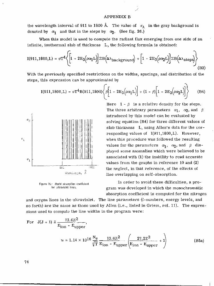
APPENDIX B
the wavelength interval of 911 to 1800 A. The value of K~ in the gray background is denoted by cul and that in the steps by 9. (See fig. 26.)
When this model is used to compute the radiant flux emerging from one side of an infinite, isothermal slab of thickness L, the following formula is obtained:
I(911718007L) = f14f1 - 2E3(palL)lZB~kbackground) i- [1 - 2E3(b2g]BB@kstepf$
(B3) With the previously specified restrictions on the widths, spacings, and distribution of the steps, this expression can be approximated by
“2
K h
ff1
1(911,18OO,L) = oT4B(911,1800)
0 Wavclcngth, A
Figure 26.- Model absorption coefficient for ultraviolet lines.
Here 1 - p is a relative density for the steps. The three arbitrary parameters ai, 012, and p introduced by this model can be evaluated by solving equation (B4) for three different values of slab thickness L, using Allen’s data for the cor- responding values of 1(911,18OO,L). However, when this procedure was followed the resulting values for the parameters 011, 9 , and p dis- played some anomalies which were believed to be associated with (1) the inability to read accurate values from the graphs in reference 10 and (2) the neglect, in that reference, of the effects of line overlapping on self-absorption.
In order to avoid these difficulties, a pro- gram was developed in which the monochromatic absorption coefficient is computed for the nitrogen
and oxygen lines in the ultraviolet. The line parameters (f-numbers, energy levels, and s o forth) are the same as those used by Allen (i.e., listed in Griem, ref. 11). The expres- sions used to compute the line widths in the program were:
For J(J + 1) 2 13.6Z2_- Eion - upper,
74

APPENDIX B
For J(J + 1) < 13.6Z2 Eion - Eupper'
Here,
J
Z
Eion
Eupper
W
Ne
w = 1.14 X lo6 - Ne 13.6Z2 \IT Eion - Eupper
angular-momentum quantum number of the upper level of the atom for absorption
charge of the atom plus 1 in units of the charge of an electron
ionization energy of the atom, cm-1
energy of the upper level, or final state, of the atom for absorption, cm-l
half of the line half-width, cm-1
electron density, particles/cm3
Although sizable differences in the half-widths of some lines as calculated by this for- mula (B5) and the formula used by Allen were noted, these differences were essentially canceled when the individual line contributions were summed over all lines at wavelengths less than 2000 A.
This program was used to compute the radiant f l u x emerging from isothermal slabs of various thickness L where only emission and absorption by the ultraviolet lines were considered. Results obtained from this calculation are presented in figure 27. The parameters a1, a2, and p displayed a great deal more regularity with variations of temperature and density when evaluated with the fluxes computed here than when they were evaluated with Allen's data.
It is expected that the step-function model for the absorption coefficient for the ". .. ~~
ultraviolet lines will give a reasonable estimate ofthe effects of absorption provided that the values of L chosen do not differ too greatly from the shock standoff distance and that the temperature distribution in the shock layer does not differ too much from isothermal.
-e
-" .
-. ~. ~ "
- " .. . "
-
75
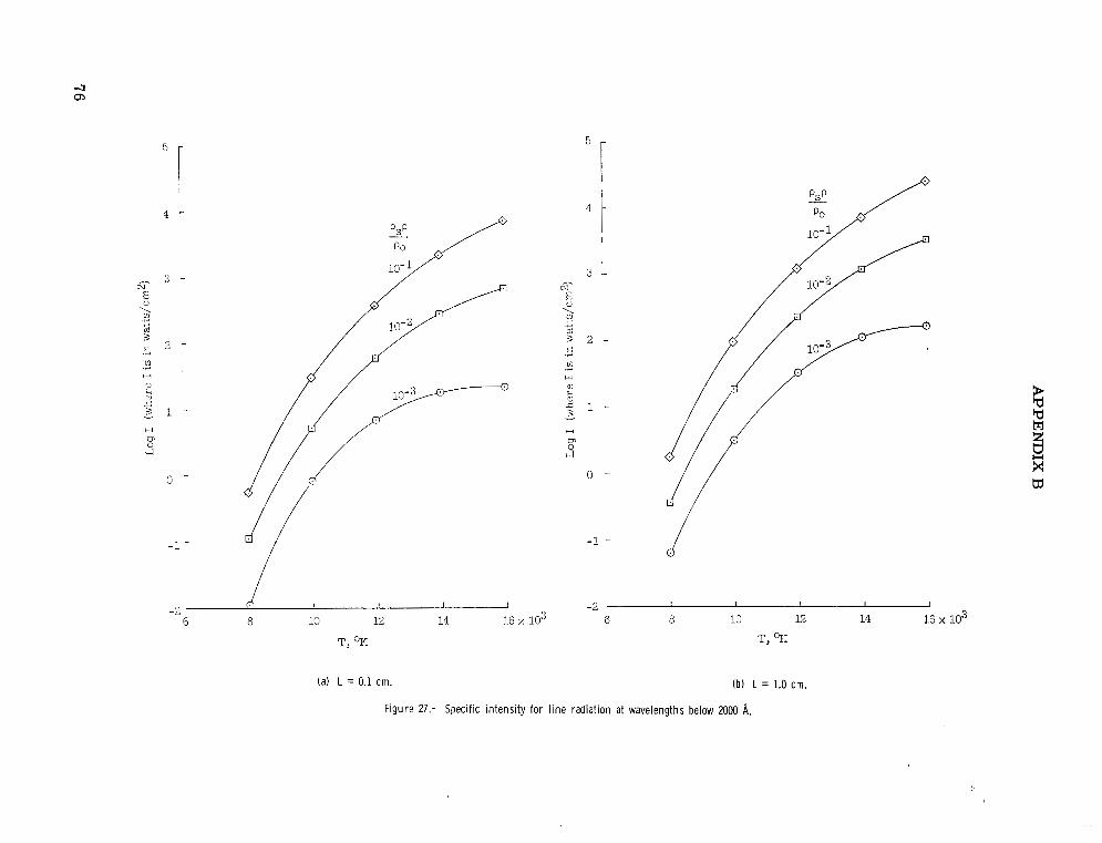
4 - 4 -
II] .3
H
3 L!
- 3 1 - H
-1 -
I
(il .i
H
H
s b, O -
-1 - d
-2 I I I 1 I
6 e I I I I
10 12 14 16 x lo3 6 e 10 12 14 16 x 103 -2
T, "K T, 'E;
(a) L = 0.1 cm. (b) L = 1.0 cm.
Figure 27.- Specific intensity for line radiation at wavelengths below 2000 A.

5 - 5 -
4 - 4 -
3 - cu-
5 5 2 -
3; +” Y
.d c il
H .r(
H
0 -
d -1 -
-2 I I I J
6 8 10 12 14 16 x lo3 T,
(c) L = 5.0 cm.
3 - cu - ! 3; c g 2 - Y
z: il .3
.A
H
a, h 2 1 - - 3 +-
0 l-
-1 t
-2 6 a 10 12 14 16 x lo3
T,
(d) L = 10.0 cm.
Figure 27.- Continued.
4 4

o i
-1 -
-2 L I I I I
6 8 10 12 14 16 x lo3 I
T, OK
(f) L = 20.0 cm.
d
Figure 27.- Concluded.
APPENDIX B
N+- and O+-Electron Recombination in the Vacuum Ultraviolet
The contribution to the optical properties of air of the N+- and O+-electron recom- bination in the vacuum ultraviolet was obtained from the data of Hahne (ref. 9). He indi- cated the existence of 12 thresholds, or photoionization edges. However, only four of them appear to be important. Consequently, the contribution to the absorption coefficient was approximated by four s teps in wavelength with edges corresponding to the threshold wavelengths of 852, 911, 1020, and 1130 A. The step corresponding to the threshold at 852 A was arbitrari ly cut off at 400 A because the emission from air appears to be negli- gible for wavelengths shorter than this. The heights of the steps were set equal to a Planck-type average of the absorption coefficient over the interval encompassed by the step. The step-function model ignores the displacement of the thresholds due to inter- action effects (see ref. 27), which tends to shift the threshold to longer wavelengths with increasing ion concentration.
Other Contributions
The remaining contributions to the optical properties of air resul t f rom a combina- tion of free-free transitions, bound-free transitions, and molecular band systems. The principal of these, along with the wavelength interval in which each is important, are as follows:
C(bound-free + free-free)
O + e - - O - + h v
N+ + e- - N + hv
O + + e - - O + h v
0 free-free
N free-free
(N+ + O+) free-free
200 - 10 000 A
Band systems
NB (1-1 3000 - 6000 A NS Meinel 5500 - 30 000 A
N2 (I+) 3000 - 20 000 A NOY 1800 - 3200 A N2 e + ) 2500 - 5000 A 0 2 Schumann-Runge 1800 - 5000 A
N2 Birge-Hopfield 1 and 2 900 - 2000 A NoP 2000 - 5800 A
79
APPENDIX B
The maximum monochromatic absorption coefficient at wavelengths greater than 1800 A is so small that the maximum monochromatic shock layer optical thickness is very much less than 1 for the temperatures, densities, and shock standoff distances of interest. Consequently, the contributions of the various radiators can be legitimately accounted for with a Planck-type average absorption coefficient for the wavelength inter- val of 1800 to 100 000 A. The contributions of the N2 Birge-Hopfield systems were approximated with Planck-type averages over the wavelength interval indicated in the table. Although the shock layer for vehicles of interest is not optically thin in portions of this wavelength interval, the Planck-type averaging is not expected to introduce any significant errors into the analysis because .absorption by these processes is small and relatively insensitive to wavelength in comparison with the group 2 contributions.
Absorption-Coefficient Model
Contributions from the three groups were combined to obtain a model for the absorption coefficient of air for a range of temperatures from 8000 to 16 0000 K and densities from 10-3 to 10-1 times the standard sea-level density. A compilation of the step-function model parameters for these conditions is presented in table I. An example of the model absorption coefficient is shown in figure 14.
80
REFERENCES
1. Olstad, Walter B.: Stagnation-Point Solutions for an Inviscid, Radiating Shock Layer. Proc. 1965 Heat Transfer Fluid Mech. Inst., Andrew F. Charwat, ed., Stanford Univ. Press, 1965, pp. 138-156. (Available also as NASA RP-599.)
2. Olstad, Walter B.: Stagnation-Point Solutions for Inviscid, Radiating Shock Layers. Ph.D. Thesis, Harvard Univ., 1966.
3. Hoshizaki, H.; and Wilson, K. H.: Convective and Radiative Heat Transfer During Superorbital Entry. NASA CR-584, 1966.
4. Goulard, Robert: Preliminary Estimates of Radiative Transfer Effects on Detached Shock Layers. AIAA J., vol. 2, no. 3, Mar. 1964, pp. 494-502.
5. Hayes, Wallace D.; and Probstein, Ronald F.: Hypersonic Flow Theory. Academic Press, Inc., 1959.
6. Howe, John T.; and Viegas, John R.: Solutions of the Ionized Radiating Shock Layer, Including Reabsorption and Foreign Species Effects, and Stagnation Region Heat Transfer . NASA TR R-159, 1963.
7. Tsien, H. S.: The Poincarg-Lighthill-Kuo Method. Vol. IV of Advances in Applied Mechanics, H. L. Dryden and Th. von Kiirmiin, eds., Academic Press, Inc., 1956, pp. 281-349.
8. Pritulo, M. F.: On the Determination of Uniformly Accurate Solutions of Differential Equations by the Method of Perturbation of Coordinates. J. Appl. Math. Mech., vol. 26, no. 3, 1962, pp. 661-667.
9. Hahne, Gerhard E.: The Vacuum Ultraviolet Radiation From Nf- and O+-Electron Recombination in High-Temperature Air. NASA TN D-2794, 1965.
10. Allen, Richard A.: Air Radiation Graphs: Spectrally Integrated Fluxes Including Line Contributions and Self Absorption. Res. Rept. 230 (Contract Nos. NASw-748 and DA-01-021-AMC-l2005(Z)), Avco-Everett Res. Lab., Sept. 1965.
11. Griem, Hans R.: Plasma Spectroscopy. McGraw-Hill Book Co., c.1964.
12. Yoshikawa, Kenneth K.: Analysis of Radiative Heat Transfer for Large Objects at Meteoric Speeds. NASA TN D-4051, 1967.
13. Chin, J in H.: Inviscid Radiating Flow Around Bodies, Including the Effect of Energy Loss and Non-Grey Self-Absorption. LMSC 668005 (Contracts NAS 9-3531 and AF 04(694)-655), Lockheed Missiles & Space Co., Oct. 12, 1965.
14. Hoshizaki, H.; and Wilson, K. H.: Viscous, Radiating Shock Layer About a Blunt Body. AIAA J., vol. 3, no. 9, Sept. 1965, pp. 1614-1622.
81

15. Thomas, P. D.: Transparency Assumption in Hypersonic Radiative Gasdynamics. AIAA J., vol. 3, no. 8, Aug. 1965, pp. 1401-1407.
16. Burggraf, Odus R. : Asymptotic Solution for the Viscous Radiating Shock Layer. AIAA J., vol. 4 , no. 10, Oct. 1966, pp. 1725-1734.
17. Nerem, Robert M.: An Approximate Analysis of Thermal Conduction and Radiative Transport in the Stagnation-Point Shock Layer. AIAA J. (Tech. Notes), vol. 4 , no. 3, Mar. 1966, pp. 539-541.
18. Hoshizaki, H.: Heat Transfer in Planetary Atmospheres at Super-satellite Speeds. ARS J., vol. 32, no. 10, Oct. 1962, pp. 1544-1552.
19. Ince, E. L.: Ordinary Differential Equations. Dover Publ., Inc., 1956.
20. Van Dyke, Milton: Perturbation Methods in Fluid Mechanics. Academic Press, 1964.
21. Kivel, B.; and Bailey, K.: Tables of Radiation From High Temperature Air. Res. Rept. 21 (Contracts AF 04(645)-18 and AF 49(638)-61), AVCO Res. Lab., Dec. 1957.
22. Armstrong, B. H.; Sokoloff, J.; Nicholls, R. W.; Holland, D. H.; and Meyerott, R. E.: Radiative Properties of High Temperature Air. J. Quant. Spectry. Radiative Transfer, vol. 1, no. 2, Nov. 1961, pp. 143-162.
23. Riethof, T.; and Nardone, M.: Radiation Theory. Doc. No. 62SD680 (Contract AF 04-(647)-617), Missile Space Vehicle Dep., Gen. Elec. Co., Aug. 31, 1962.
24. Nardone, M. C.; Breene, R. G.; Zeldin, S. S.; and Riethof, T. R.: Radiance of Species in High Temperature Air. Tech. Inform. Ser. R63SD3 (Contract AF 04(694)-222), Missile and Space Div., Gen. Elec. Co., June 1963. (Available from DDC as AD No. 408564.)
25. Biberman, L. M.; and Norman, G. E,: Rekombinatsionnoye i Tormoznoye Izlucheniye Plazmy (Emission of Recombination Radiation and Bremmstrahlung From Plasma). J. Quant. Spectry. Radiative Transfer, vol. 3, no. 3, July-Sept. 1963, pp. 221-245.
26. Sherman, M. P.; and Kulander, J. L.: Free-Bound Radiation From Nitrogen, Oxygen, and Air. Rept. No. R65SD15 (Contract Nonr-4188(00)), Gen. Elec. Co. , May 1965.
27. Biberman, L. M.; Iakubov, I. T.; Norman, G. E.; and Vorobyov, V. S.: Radiation Heating Under Hypersonic Flow. Astronaut. Acta, vol. X, fasc. 3-4, 1964, pp. 238-252.
28. Vorobyov, V. S.; and Norman, G. E.: Energy Radiated in Spectral Lines by an Equilibrium Plasma. 11. Opt. Spectry. (USSR), vol. XVII, no. 2, Aug. 1964, pp. 96-101.
82
NATIONAL AERONAUTICS AND SPACE ADMINISTRATION WASHINGTON, D. C. 20546
OFFICIAL BUSINESS FIRST CLASS MAIL NATIONAL AERONAUTICS ANI
POSTAGE AND FEES PAID
SPACE ADMINISTRATION
POSTMASTER: If Undeliverable (Section 158 Postal Manual) Do Not Rerun
- " -
"The aeronautical and space activities of the United States shall be colzdzlcted so as t o contribute . . . to the expansion of human knowl- edge of phenomegza in the atmosphere avad space. T h e Administratio?z shall provide for the widest practicable and appropriate disseminatiolz of infor?untion concerning its activities and the results thereof."
-NATIONAL AERONAUTICS AND SPACE ACT OF 1958
NASA SCIENTIFIC AND TECHNICAL PUBLICATIONS
TECHNICAL REPORTS: Scientific and technical information considered important, complete, and a lasting contribution to existing knowledge.
TECHNICAL NOTES: Information less broad in scope but nevertheless of importance as a contribution to existing knowledge.
TECHNICAL MEMORANDUMS: Information receiving limited distribution because of preliminary data, security classifica- tion, or other reasons.
CONTRACTOR REPORTS: Scientific and technical information generated under a NASA contract or grant and considered an important contribution to existing knowledge.
TECHNICAL TRANSLATIONS: Information published in a foreign language considered to merit NASA distribution in English.
SPECIAL PUBLICATIONS: Information derived from or of value to NASA activities. Publications include conference proceedings, monographs, data compilations, handbooks, sourcebooks, and special bibliographies.
TECHNOLOGY UTILIZATION PUBLICATIONS: Information on technology used by NASA that may be of particular interest in commercial and other non-aerospace applications. Publications include Tech Briefs, Technology Utilization Reports and Notes, and Technology Surveys.
Details on the availability of these publications may be obtained from:
SCIENTIFIC AND TECHNICAL INFORMATION DIVISION
NATIONAL AERONAUTICS AND SPACE ADMINISTRATION Washington, D.C. 20546