Embed Size (px)
Citation preview
--- -----11 lm_
AIAA 2002-0838
TRANSONIC DRAG PREDICTION
USING AN UNSTRUCTURED
MULTIGRID SOLVER
D. J. Mavriplis
ICASE
MS 132C, NASA Langley Research Center
Hampton, VA
and
David W. Levy
Cessna Aircraft Co.
Wichita, KS
40th AIAA Aerospace Sciences Meeting
January 14-17 2002, Reno NV
For permission to copy or republish, contact the American Institute of Aeronautics and Astronautics1801 Alexander Bell Drive, Suite 500, Reston, VA 20191-4344
https://ntrs.nasa.gov/search.jsp?R=20020019227 2020-04-23T15:17:27+00:00Z


TRANSONIC DRAG PREDICTION USING
AN UNSTRUCTURED MULTIGRID
SOLVER
D. J. Mavriplis
[('ASE
IkIS 132('. NASA Langley Research Center
Hampt(m. \'A
_lll(I
David VV. Levy
C'essna Aircraft C_.
\\ichita, KS
Abstract
This paper sunmlarizes the results obtained with the
NSt'3D unstructured multigrid solver for the :\IA.\
Drag Prediction Workshop held in Anaheim. ('A, .hme
2001. The test case for the workshop consists of a
wing-body configuration at transonic flow conditions.
Flow analyses fi)r a conlplete test matrix of lift coeffi-
cient values and Math numbers at a constant Reynolds
number are performed, thus producing a set of drag
polars and drag rise curves whMl are compared with
exp(,rimental data. l-lesults wer(- obtain('d ind('t)('n-
dently by both authors using an identical baseline grid.
and different refned grids. Most cases w(,ro run in
parallel on commodity cluster-type machines while the
largest cases were run on an SGI Origin machin(, using
128 processors. The ot)jectiv(' of this t)aper is t() study
the accuracy of the subject unstructured grid solver
for predicting drag in the transonic cruise regime, to
assess the efficiency of the method in terms of conver-
gell('e, cpu tillle alld illelllory, and to (teternfino the
effects of grid resolution on this predictive ability and
its computational efficiency. A good predictive abil-
ity is demonstrated over a wide range of conditions.
although accuracy was found to degrade for cases at
higher Math numbers and lift vahtos where hwreas-
ing amounts of flow separation occur. The ability to
rapidly compute large numbers of cases at varying flow
conditions using an unstructured solver on inexpensive
clusters of commodity computers is also demons( rated.
Introduction
Computati(mal fluid dynanfics has progr(,ssed to the
point where Reynolds-averaged Navier-Stokes solvers
have become standard simtflation tools for predict-
ing aircraft aerodynamics. These solvers at'(' r()utinoly
('opyright ,_') 2002 by the American [n,,,titute of \erorlm, tics
a.rld \.,,tr'onautilb. Inc. -\11 riRht,b re_.erved.
] OF
us('d t,) pr(,dict aircraft flw('e coefficients su('h as lift.
drag and moments, as well as the changes in these
values with design changes. In order to be usofifl to
an aircraft designer: it is generally acknowledged that
the computati(mal niethod should I)(' cat)abh" of pre-
dicting drag to within several counts. Whih' Reynolds-
averaged Navier-Stokes solvers have made great strides
in accuracy and affordal)ility over the last decade, the
stringent accuracy requirements of the drag prediction
task have proved difficult to achi('ve. This difficulty is
('onll)ounde(t by the multitude of Navier-Stokes solver
fornmlations availabh.', as well as by the effects on
accuracy of turbulence modeling and grid resolution.
Therefore. a particular Navier-Stokes solver must un-
dei'go extensive validation including th(, deternfination
of ado(tuate grid resolution distribution, prior to being
trusted as a usefi.fl predictive tool. With these issues in
mind, the AIAA Applied Aerodynamics technical com-
mittee organized a Drag Prediction Workshop, held
ill Anahoiln CA..hm(' 2001.1 in order to assess th,'
predictive capabilities of a number of state-of-the-art
computational fluid dynamics methods. The chosen
configuration, denoted as [)LR-F4'-' and depicted in
Figure 1. consists of a wing-body geonwtr.v, which is
represontativ(' of a modern sup('rcritica[ swept wing
transport aircraft. Participants included Reynolds-
averaged Navier-Stokes formulations based on block-
structured grids, overset grids, and unstructured grids.
thus affording an opportunity to compare those meth-
ods Or!. all equal basis in terms of accuracy and (,ffi-
ciency. A standard mesh was supplied for each type
of methodology, with participants encouraged to pro-
duce rosuhs on additionally refined meshes, in order to
assess the effects of grid resoluti(m. A Math number
v('rsus lift (:oeffM(,nt (('I.) matrix of test cases was de-
fined: which included mandatory and optional cases.
The calculations were initially run by the participants
without knowledge of the experimental data. and a
l0
.\MERIUAN ]NS'FITI'TE OV _\ EnONAITI('q AND \_;II(ONAVTICS PAPER _2002 08fin

c(,npilation of all workshop results including a statis-
tical analysis of these results was perf()rmed t)3 the
conlnlit t(_(L :_
Fig. I Definition of Geometry for Wing-Body
Test Case (taken from Ref. _')
This paper describes the results obtained for this
workshop with the unstructured mesh Navier-Stokos
soh'er NSU3D. _-6 This solver has been well validated
attct is curr('ntly in use in both a research setting and
an industrial production onvironnlcnt. Results were
obtained independ(,1My by both authors on file base-
line w()rksh(q) grid. aim on two refined grids gencrate(t
independently by both authors. All required and op-
tional cases were run using the baseline grid and one
refined grid, whih" the most highly refined grid was
Oll[y full 1)I1 the ltlalldatory ('_ts('s, Th(' fUllS w('ro per-
formed on thr_x' different types of parallel machines at
two different h.)cations.
Flow Solver Description
Tlw NSU3D cod(' s()lv('s the Reynolds averaged
Navier-Stokes equations on unstructured meshes of
mixed element types which may include tetrahedra,
pyramids, prisms, and hexahedra. All elenu, nts of the
grid are han.dled bv a singh' unifying cdge-base(l data-
strttctur_ _ in the flow solver. I
Tetrahedral elements are employed in regions where
the grid is nearly isotropic, which generally correspond
to regions of inviscid flow. and prismatic (:ells aw em-
ph)y('d in regions close to the wall. such as in boundary
layer regions where the grid is highly stretched. Tran-
siti_m b_-tw('en prismatic and tetrahedral cell regions
occurs naturally when only triangular prismatic faces
art, exposed to the tetrahedral region, but requires a
small numt)er i)f pyramidal o'lls (calls fornwd by 5 ver-
tices) in cases where quadrilateral prismatic faces are
exposed.
Flow variables are stored at the vertices of the mesh,
and the gov(,rl|ing equations are dis(:r('tized using a
central (lifferenc,' finir,'-vo[mue technique with ad(h'd
artificial dissipation. The matrix formulation ()f the
artificial dissipation is employed, which corresponds
to an upwind scheme based on a Rue-Riemann solver.
The thin-layer fiJrm (ff the Navier-Stokes equations is
employed in all cases, and the viscous terms are dis-
cretized to second-order accuracy by finit_'-diff('r(mce
approximati(m. I F(_r muhigri([ calculati(ms, a first-
order discretization is employed for the convo('tive
[(H'nts on the coarse grid levels.
The basic time-stepping scheme is a three-stage ox-
plMt multistage s('hem_' with stag(' c(,'ffi('i(q_ts Ol)ti-
mized for high fr_,qUClWy dalnl)ing l)roperties. 7 an(t
a CFL number of 1.8. Convergence is accelerated
by a local block-.lacobi preconditioner in regions of
isotropic grid ('ells. which involvf,s inverting a 5 x 5
matrix for each verwx at each stage. _ 10 In bound-
arv layer r_'gions, whor_, the grill is highly stret('lw(t.
at line smoother is entphued, which involves inverting
a block tridiagonal along lines constructed in the un-
structured mesh by grouping together edges normal to
the grid str_,tching ([ire('tion. Th(' lint' sm(_othing te('h-
hi(lug' has been shown to relic're the numerical stiffness
associated with high grid anisotroI)y.[I
An agglomeration multigrid algorithm |` 1_ is used
to further enhance convergence to steady-state. In
this approach, coarse levels are c(mstruct(,d by flls-
ing together neighboring fine grid control volumes to
form a smaller number of larger and more complex
control volumes on the coarse grid. '['his process is
i)e|'fbrm(,d automaticalh" in a pre-processing stage by
a graph-based algorithm. A multigrid cych, consists
of performing a time-stop on the fine grid of the se-
quence, transferring the flow solution and residuals to
the coarser hwel. perfl)rming a time-step on the coarser
level, and then interpolating the corr('cti_)ns back from
th(' coarse lev('l to update the fine grid soluti(m. The
process is applied recursively to tit(., coarser grids of
the seqtl(_nce.
The single equation turbul(,nce model of Spalart and
kllmaras 1:_ is utilized to a('('OUllt for turbulence ef-
fects. This ('(luation is discrotized and solved in a
manner completely analogot|s to the flow equations.
with the exception that the convective terms are only
discretized t,) first-order accuracy.
The unstructur(,d multigrid solver is parallelized
by partitioning the domain using a standard graph
partitioner _ and communicating between the various
grid partitions running on individual processors us-
ing either the MPI message-passing library.l; or the
OpenMP compiler directives, t6 Since OpenMP goner-
ally has been advocated fi)r shared memory architec-
tures, and MPI for distributed memory archite('tures,
this dual strategy not only enables the sol\'(,r to run
('ffi('iently on both types of memory architectures, but
can also be used in a hybrid two-level mode, suitable
for networked clusters of individual shared memory
multi-processors. _ l%r tit(, results presented in the pa-
p_,r, the s,)lver was run ()n distributc(t /u('mury PC
2OF IO
,\MERIt'AN [N>;TITI'TE OF AERONAIFICS ANI) ;\_,rI'IIONAI'TI('% [)APEII 2002 (),N3N

clusters and an SG[ Origin 20(}0. using the MPI pro-
grarnming model exclusively.
Grid Generation
Th(' bas('lin(' grid supplied for th(" workshop was g('n-
crated using the VGRIDns package. *r This approach
produces fully tetrahedral meshes, although it is ca-
pable of generating highly stretched semi-structuredtetrahedral elements near the wall in the boundary-
lay('r r('_i()ll, and (,nlph)ys ll!.od(}rat(' spanwis(' str(,tt'h-
ing in order to reduce the total number of points. A
semi-span g(,ometry was modeled, with the far-field
boundary located 50 chords away from the origin, re-
suiting in +tt(+tal of 1.65 nfillion grid points. 9.7 millitm
t(-trah<'(lra, and 36.1)1)0 wing-body surfac(' points. The
chordwise grid spacing at the leading edge was pre-
scribed as O.25O mm and 0.500 nun at the trailing
edge. using a dimensional mean chord of 142.1 nml.
Th(- trailing ('dge is t)hmt, with a base thi('kn('ss of0.5 '/ chord, and the t)aselin(' mesh contain('d 5 grid
points across the trailing edge. The normal spacing atthe wall is 0.001 mm, which is designed to produce a
grid spacing corresponding to f- = 1 for a Reynolds
lllunb('r ()f 3 million. A stretching rat(' of 1.2 was pre-
s('rib('d for th(' gr()wth of cells in th(' llortnal directi(mnear the wall. in order to obtain a tllinimunl of 20
points in the boundary lay(,r.Becaus(" the NStTaD solver is optimized to run on
ufix(,d (,h'm('nt m(,sh('s, the fltlly totrahedral bas(,linc
mesh is subsequently converted to a mixed element
nlesh by merging the send-structured tetrahedral lay-ers in th(" boundary layer region into prismatic eh.'-
nlents. This is done in a pre-processing phase where
triph'ts ,>f tetrah('ttral lay('rs are identifi('d and m(,rg('d
into a single prisnlatic eh,ment, using information iden-
tif_ving these elements as behmging to the stretched
viscous layer region as opposed to the isotropic inviscid
tetrah(,dral region. The merging operation results in atotal of 2 million creat(,d prismatic eh_nt('nts, whih' thenuml)er of tetrahedral cells is reduced to 3.6 million,
and a total (.)f 10090 pyramidal elements are created to
nl(,rge prismatic elements to tetrahedral eh.'m('nts in
regions where quadrilateral faces from prismatic ele-
ments are adjacent to tetrahedral elements.
A higher resolution mesh was generated t)3: the sec-
ond author using VGRIDns with snlaller spacings in
ttl(' vicinity of the wing root. tip. and trailing ('dg(',
resulting in a total of 3 million grid points, and 7a.000
wing-body surface points. One of the features of this
refined grid is the use of a total of 17 points across the
wing trailing ('dge v('rsus 5 for th(' bas(,line grid. After
th,' m('rging operathm, this grid ('()ntained a t,Jtal ()f
3.7 million prisms and 6.6 million tetrahedra.An additional fine mesh was obtained 1)y the first
attthor through global retinement of the baseline work-
shop m(,sh. This strategy op(,rates (tir(,('tly on th('
mixed prismatic-tetrahedral mesh. and consists of sub-
dividing each element into 8 smaller self-similar eh>
ments, thus producing an 8:1 refinement of th(" originalmesh. Is The final mesh obtained in this manner con-
tain('d a total of 13.1 million points with 16 million
prismatic elem('nts and 288 million t(,trah('dral eh'-
ments, and 9 points across the bhmt trailing edge of
the wing. This approach can rapidly' generate very
large meshes which would otherwise be very time con-
suming t() construct using th(' original m,,sh generationsoftware. One drawback of' the current approach is
that newly generated surface points do not lie exactly
on the original surface description of the model geom-
etry, but rather along a linear interpolation between
pr,,vi()usly existing surface coarse grid points. D)r a
single level of refinement, this drawback is not ex-
pected to have a noticeable effect on the results. An
interface for re-projecting new surface points onto the
original surface geometry is currently un(h'r ('onsid(,r-ation.
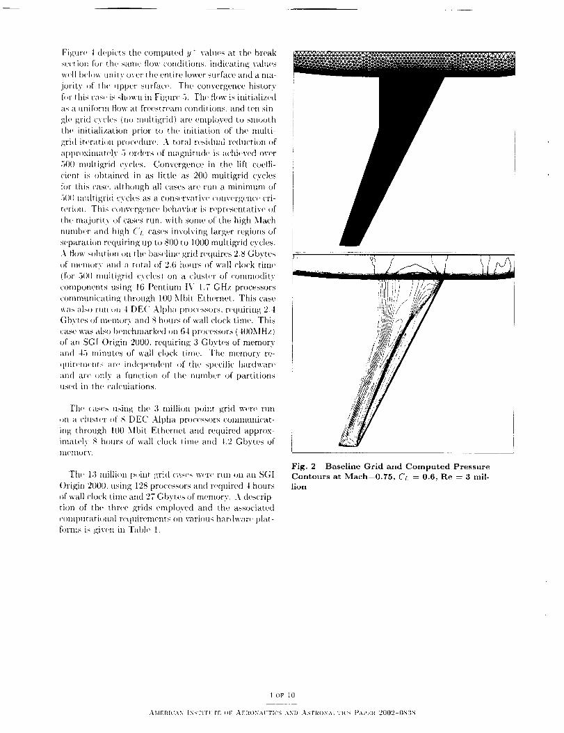
The baseline grid was found to be sufficient to re-
solve all major flow features. Tile computed surface
pressure coefficient on the baseline grid for a Math
numb('r of 0.75, Reynolds numb(,r (>f 3 million, and
('t 0.6 is shown ill Figure 2. illustrating good reso-
lution of tile upper surface shock. A small region of
separation is also resolved in the wing root area. as
shown by the surface streamlin('s for the same flow
conditions, in Figure 3.
Table 1 Grids and Corresponding Run Times
Grid No. Points
Grid 1 1.65× 10°
Grid 1 1.65 × t0 G
Grid 1 1.65 x 10 (i
Grid 2 3.0 x 1(I(;
Grid 3 13 x 106
No. T('ts
2 x 1()(s
2 x 10°
2 x 1(1(;
3.7 x 10a
16 x 10o
No. Prisms3.6 x 10_
3.6 x I ()(_
3.6 x 10"
6.6 x 10"
28.8 x lt/°
Memory
2.8 Gbytes
2.1 Gbytes3.0 Gbytes
4.2 Gbytes
27 Gbytes
_tln Time
2.6 hours
8 hours
45 min.
8 hours
I hours
Hardware
16 Pentium IV 1.TGHz
I DEC Alpha 2126.1 (667MHZ)64 SGI Origin 21)I)t) (400MHz)
8 DEC Alpha 21264 (667MHZ)
128 SGI 02000 (100MHz)
3 oF It)
AMERIt'AN INSTITUTE OF :\ERONAI:T[(_S AN[) ASTRONAII'IL_S PAPER 2002 083s
Figuro 1 dopicts the computed y + vahLos at tho break
sovt i,m fl_r tho sanw flow conditions, indicating vahu,s
woll bvl(,w unity ovor the ,,nt iro lower surfaco arid a nla-
jority of thv upper surfaco. Tho convergenec history
fl_r this cast is showu in Fig;urv 5. Thv fl<_w is initializ_,d
as a _mif'.rm flow at freesu'vam conditions, and tan sin-
gh' grid cych's (no muliigrid) aro onlptoyed to smooth
the initialization prior to thv initiation of the nlulti-
grid [tvration proeeduro. A total t'vsidual reduction of
aplWOXintatvly .3 ordors of magnitudv is achivvvd ovor
500 multigrid cycles. COl'lvergen(:e in the lift coetti-
ciont is obtained in as little as 200 multigrid cycles
for Ihis cas_,, although all cases aro run a minimum of
.3[)[) nmLtigri([ cvclos as a consvrvativv cotlvot'g(qlt'v cri-
rotion. This convvre;on('e behavior is reprosentative of
thv majority ,_t' cases run. with somo of the high Math
number and high ('r. cases involving larger rogions of
soparation roquiring tip to 800 to 1000 multigrid cycles.
A flow solution oil the baselin(' grid roquiros 2.8 Gbvtcs
of tn,'m_,rv and a total of 2.6 hours of wall clock time
(fl)r 500 muttigrid cycles) on a cluster of comm<_dity
components using 16 Pentium IV 1.7 GHz processors
comnnmicating through 100 Mbit Ethernet. This case
was also run on 4 DE(' Alpha processors, roquiring 2.4
Gbytos of memor.v and 8 hours of wall clock timo. This
case was also benchmarked otl 64 processors (,I00MHz)
of an SGI Origin 2000. requiring 3 Gbytes of memory
and 45 minutes of wall clock time. The momory re-
quit'olnVnts aro iiMel)endont _)f the spvcific hardwar,'
and arv _mlv a functiotl of tho number of partitions
used in the, calculations.
Tho cases using the 3 million point grid woro run
on a chtstor _,f g DEC Alpha prot>ssors comnmnicat-
ing through It){) Mbit Ethernvt and roquired approx-
imatoly S hours of wall clock time and t.2 Gbytos of
mvmory.
Th,' 13 million p_Jinr xt'id casos w,,rc run on an S(;I
()rigin 2000. using 128 processors and roquired I hours
of wall clock time and 27 Gbyws of memory. A descrip-
tion of the three grids emph)yed and the associated
/'()lllptltatioll;ll rv([uirOlllOlltg oil various hardwar(' plat-
forms is givvn ill Tabh' 1.
Fig. 2 Baseline Grid and Computed Pressure
Contours at Mach=0.75, Cr = 0.6, Re ---- 3 mil-
lion
i o_" I 0
AME[tIUAN INSI'ITI" rE OF ,kF.RONAUTIUS ANI') ASTRONAUTICS [_APER 2002 I)83S

Fig. 3 Computed Surface Oil Flow Pat-
tern in Wing Root Area on Baseline Grid fi)r
Math=0.75, Cr = 0.6, Re = 3 million
_b
2
• i i i i i L
Nlllllber _q ('vde_,
Fig. 5 Density Residual arid Lift Coefficient
Convergence History as a Function of Multigrid
Cycles on Baseline Grid for Mach----0.75, ('L =
0.6, Re = 3 million
11
1
0.9
0.8
07
06
05
03
04
02
-- Lower Surface
Upper Surface
\\'\_ /
I I i i I I I i I I i i
025 05
XlC
iiIilll
0 75
Fig. 4 Computed y+ on wing surface at spanbreak section on baseline grid for Mach----0.75,
C:. : 0.6, Re : 3 million
Results
The workshop test cases compris('(t two rt,quired
cases and two optional cases. These cases are described
in "Fable 2. For all cases the Fleynol(ts numl)er is 3 mil-
lion. The first test ease is a singh, p_int at Math
0.75 and C:, = 0.5. The second test case involves the
computation of the drag polar at Math=0.75 using in-
ci(lencos from -3.0 to +2.0 degrees in increments of 1
degree. Th(' optional Casos 3 and 4 involve a matrix
of Math and ('t. valu(,s in order to ('onip_lto drag rise
curves. Since an automated appr()ach for computing
fixed Cr cases has not been implemented, a complet('
drag polar for each Math number was c'oml)ut('d fl)r
(!ases 3 and 4. For the baselin(' grid. the incidence for
the prescribed lift value was then int('rl)olated from
the drag t)olar using a cubic spline fit. and the flow
was recomputed at this prescribed incidencv. The fi-
nal force coefficients wero then interpolated from the
values computed in this ('ase to the pr(,scribed lift vai-
llCS. which ar(" very close to the last ('()In.l}uted case.
D_r the 3 million point grid. the force c()(4ficient val-
ues at the prescribed lift conditions wore interpolated
directly fi'om th(, 6 integer degree cases within each
drag polar.
5 ()F t0
.\MEIH('AN INSI'II'ITE OF ,\EI(ONAI'FI('S \ND ,\STItON:\ViI_'S [L\PER 2[)()]2-087{S

Table 2 Definition of Required and Optional
Cases for Drag Prediction Workshop
Case Descript ion
Case I ( tl eq u i t'('d )
Single l)oint
Case 2 (Ih,quirod)
Drag Polar
Case 3 (()pti<mal)
Constant ('t
Math Sw('ep
Case I (()ptional)
Drag Rise Curw, s
Math = 0.73. C-'t = 0.500
_lach = 0.73
+_ 3". 2". I",O °. 1".2 _'
._lach = .50..6().. 70.. 75_ 76_ 77..78..80
Cr = 0.300
lach = .50,. 60_ 70.. 75.. 76.. 77.. 78,. 80
Cr = 0. 100.0.500.0.600,
All cases wer(' computed using the baseline grid
(I.6 milli<m points), and the nu'dium grid (3 million
points). Only the required cases were computed using
the finest grid (13 million points) due to time con-
straints. Table 3 depicts the results obtained for Case
1 with the three different grids. Th(" drag is seen to be
('(mq)uted accurately by all thr('(' grids, although tlwr('
is a 10.6 count variation between the 3 grids. How-
ever. the incidence at which the prescribed C,+ = 0.3 is
achieved is up to 0.6 degrees lower than that observed
experimentally. This effect ix more evident in the ("L
v('rstts [n('i(h,nc(, plot of Figure 6, where the computed
lift values are consistently higher than the experimen-
tal values. Sittce this discrepancy increases with the
higher resohttion grids, it cannot be attributed to a
lack of grit[ res<)httion. Tit<' slope of th(' computed
lift. curve is about 5c/( higher than the experimentally
d<,termitled slope, attd is [argety unalfected by grid res-
olution.
Figure 7 provides a comparison of computed surface
pressure coefficients with experimental values at the
experimentally prescribed C',, of 0.G (where _t1<' effects
are more dramatic than at CL 0.5) as well as at the
experimentally prescribed incidence of 0.93 degrees, at
the 10.9 _ span location. When the experimental inci-
dence value is matched, the computed shock location
is aft ()f tit<' (-xp('rim('ntal values, and th(, computed
lift ix higher than the experimental value, whih, at the
prescribed lift condition, the shock is further forward
and the suction peak is lower than the experimental
val tit'S.
This bias in lift versus incidence was obsm'vod for a
majority of the nunwrical solutions submitted to the
workshop. :_ and thus might b,' attributed to a model
g_,,onletry eP[ect or a wind tunnel correction eIfect, al-
though all exact catlse has nol he('n determin+,d. \Vhen
plotted as a drag polar. Cr versus CD as shown in
Figure 8, the results compare favorably with expori-
n|ental data. Although the (trag polar was computed
independently by both authors using tile baseline grid.
the results of both sets of computations were identical
(as expected) and thus only one set of computations
is shown for the baseline grid. The ('<mH)utatiomd r('-
sults on this grid compar,, v(,ry well with exlwriment
in the mid-range (near Cr. = 0.3), while a slight over-
prediction of drag is observed for low lift vahtes, which
decreases as the grid is refined.
This behavior suggests an und('r-prediction ()f in-
duced drag, possibly due to inadequate grid resolution
in the tip r(,gion or ds(,wlwr< The absolute drag h'v-
('Is have heen found to b(' sensitive to the d('gr('(' ()f
grid refinement at the blunt trailing edge of the wing.
The drag h'vel is reduced by I count.s wh('n going from
the 1.6 million point grid. which has 5 points on the
trailing edge, to the 3 million point grid. which has
17 p()ints oil the trailing edge. Internal studies bv th('
second author using structured grids hay<, shown that
up to 33 points on the bhmt trailing edge are required
before the drag does not decrease any further. In the
current grid gelleratioll ('llvir()lUll('llt. 0.lid without the
aid of adaptive meshing techniques, the gen(.,ration of
highly relined trailing edge unstructured meshes has
be('r! f(.)und to be problenmtic, thus limiting our study
in this ai'(,a.
Figure 9 provides an estimate of the induced drag
factor, det('rmined experimentally and computation-
ally on tit(., three meshes.
Table 3 Results for Case 1; Experimental
Values I:ONERA, 2:NLR, 3:DRA; Gridl': Per-
formed by first author, Grid1+: Performed by
second author. Experimental data and 3 M
point grid results are interpolated to specified
Ct condition along drag polar.
Case
Experiment I
Experiment e
Experinmnt :_
Gridl ( 1.63lets)*
Gridl ( 1.6+llpts) +
Grid2(3.0Mpts)
Grid3( la3Ipts)
CL
0.5000
0.5000
0.5000
0.500,1
0 A995
0.5000
(}.5(}03
(_ CD
+.192 ° 0.02896
_-.15W 0.02889
+.179" 0.02793
-.241 '_ 0.02921
-.248'-' 0.02899
-.117 '_ 0.02857
.367" ().02815
C;t/-
-.13(}1
-.1260
-.1371
-. 13,19
-. 1348
-.1613
-.1657
6 OF 10
AMERICAN ]NNTITITE t')F AERONAI'TI(% AND ,\STRONAUTICS PAPER 2002 [),v,3S

0.8 0.8
0.7
0.6
0.5
(S04
0.3
0.2
0.1
0.0,
/_-(]D O M=.75, NLR-HST
__/_1 [] M=.75, ONERA-S2MA
o u_-.7_ORA-Sx8_ 1.6M Grid
13.1M Grid
1.6M Grid
----C-_- 3.0M Grid
.... I .... l .... l .... i .... ' ' ' '-2 -1 0 1 2
Alpha
Fig. 6 Comparison of Computed Lift as a
flmction of Incidence for Three Different Grids
versus Experimental Results
07
0.6
0.5
¢'J_0.4
03
0.2
0.1
0.0
_..t
_#- [No,.:,,io,,,,,oo.,d.,-,,,,,.w1AI_ I pr_-scribed b'Ip pattern; I
Lc_c__od,==,._,,_,turbulentL--o2,_.;2o
,_/ a M=.75,ONERA-S2MA_J,j/ O M=.75, DRA*8x8
^_r_ ---C,----- 1.6M Gridv• _ 13.1M Grid
_ 1.6M Grid
--- _,"-_ 3,0M Grid,01 i , , , I , , , , I , _ , , I
0.020 0.030 0.040 0.050
Co
Fig. 8 Comparison of Computed versus Exper-
imental Drag Polar for N'Iach----0.75 using Three
Different Grids
15
-05
n
0
05
NSU3D: Alpha = 0.93NSU3D: CL= 0.6
r_ll_._ ' • Experiment: Alpha=O,93
i ; I I i I I I I i I i i I .... I0 25 05 075
X/C
Fig. 7 Comparison of Computed Surface Pres-
sure Coefficients at Prescribed Lift and Pre-
scribed Incidence versus Experimental Values
for Baseline Grid at 40.9 % span location
0.6
[] M=.75, ONERA-S2MAj_7 O M=,75, DRA-Sx8
._z 7 _ 1.6M Grid
-_ 13.1M Grid
._')_ .... + 3.0_M Gddl,_I i _ I J L i I i
0-0-20 0.030 0.040 0.050
Co
0.5
0,4
0.3
0.2
0.1
0.0
Fig. 9 Comparison of Computed versus Exper-imental Induced Drag Factor for Math----0.75
using Three Different Grids
7 OF 10
._[E['[I('AN INb;I'I'TI'FE OF .\ERONAI-TI('t'-; AND ,_TR()NA[ ['[('N PAPER '200:2 (),S;{_

0.8
0.7
0,6
0.5
o0.4
0.3
0.2
0.1
00%
-4F'Coun"
_{ _l_ O "=.75, NLR-HST
_iI [] M=.75,ONERA-$2MA;; _a_- ,.;,;,G&..-,-
O o _ 13.1M Grid
_---- 3.0M Gdd
,,l:g,I, ,I,,,I , li ii|_ , , [, ; _ I i _ _
0,020 0.024 2 0.028 0.032Cop= C o - C,/(x AR)
Fig. 10 Comparison of Computed ver-
sus Experimental Idealized Profile Drag at
?viach=0.75 using Three Different Grids
-0"08 f O M=.75, NLR-HST !i
O M=.75, ONERA-S2MA
-0.10 O M=.75, DRA-ax81.6M Grid
13.1M Grid
--<2,---- 3.0M Grid on I
OOOOOOOOO
= .==oO.,ooooo_ I0
_0.14ooooo:S?:o>OOOOj / I-0.t6
.,I .... I, ,,1 .... I , ,1 ilJl I i I I I
0 1 0.1 0.2 0.3 0.4 0.5 0.6 0.7 0.8. . , i , i
CL
Fig. 11 Comparison of Computed versus Ex-
perimental Pitching Moment for Mach=0.75
using Three Different Grids
For C'I-' up to ahout 0.36. when the flow is mostly
attached, induced drag is underpredicted by approxi-
mately 10 _X. as determined by comparing the slopes
of the computational and experimental curves (using
a linear ctlrve fit) in this wgion. Grid refinement ap-
pears to have litth' effect on the induced drag in this
region. At the higher lift values, the 3 million point
grid yields higher Cr and lower Cr) vahtes, which is
attributed to a slight delay in the amount of predicted
8oF I0
AMERI{'AN [NSTIrFI'TE (H" ;\I<I{ONAI I'I('S AND ;_;TRONAIT1CS PAPER 2002-0s:},s
flow separation. Results for the 13 million point grid
are not shown, since a fully converged solution t'ould
not be obtained at the highest incidonce. On the of her
hand. il should be noted tha.t the wind tllnnel ('xper-
iments used a boundary layer trip at 15'/_ and 25(X
chord on the tipper and lower surfaces, while all cal
cttlations were performed in a fully turl)ulent mode.
Examination of the generated eddy viscosity h.wels in
the calculations reveals appreciabh, levels b,'gi,ming
])etw,'en 5'X to 7(J chord. The exact influence of tran
sition h>cation on overall computed force coefficients
has not t)_,en quantified and requires further study.
Figure l(/ shows the idealized profile drag I_ which
is defined by' the tbrmula:
CDt, = CD - Cr-'/(rc.4R) (1)
where AR is the aspect ratio. Plotting Cr>r generally
results in a more compact representation of the data,
allowing more expanded scales. It also highlights the
characteristics at higher Cr, where the drag polar be-
comes non-parabolic due to wave drag and separation.
In the non-parabolic region, the error in drag is rela-
tively large at a constant Cr.
The pitching moment is plotted as a function of Cr
in Figure 11 for all three grids versus experimental
vahtes. The pit('hing niotnent is substan.tially mM('t'-
predicted with larger discrepancies observed for the re-
fined grids. This is likely a result of the over-prediction
of lift as a [hnction of incid_,nce, its mentioned earlier
and illustrated in Figure 6. Because the computed
shock location and suction peaks do not line up with
experimental values, the predicted pitching moments
can not be expected to be in good agreement with ex-
perimental values.
Figure 12 depicts the drag rise curves obtained for
Cases 3 and 4 on the baseline grid and the first refined
grid (a million points). Drag values are obtained at
four different constant Ct, values for a rang,, of Math
ntunbers. Drag values are predicted reas,mal)ly well
except at the highest lift and Math number conditions.
There appears to be no improvement in this area with
increased grid resolution, which suggests issues such as
transition and turbulence modeling may account for
these discrepancies. However. since the two grids have
comparable rosolution in various areas of the dolnain.
grid resolution issues still cannot be ruled out at this
stage.
The results obtained for Cases 3 and I can also be
plotted at constant Math number, as shown in the
drag polar plots of Figure 13. The plots show simi-
lar trends, with the drag being slightly, ow,rpredicted
at low lift values on the coarser grid and with the re-
fined grid achieving better agreement in these regions.
For the higher Math numbers, the drag is substantially
tmderpredicted at the higher lift values. These discrep-
ancies at the higher Math numbers and lift conditions

pointto anunder-predictionoftheextentof the S_'l)- 0.056
arated regions of flow in the numerical simulatkns
The comparison of idealized profile drag in Figure l() 0.052
also sugg_'sts that the drag due to flow sq)aration is
not predicted accurately at the higher lift conditions. 0.048
However. the character of the turves also suggest that0.044
the error may be due as well to the CL offset (shown
in Figure 6). Additional information c(mcerning the 0.040ta
regions of flow separation found in tlw wind tunnel O
would be needed to tll()I'(' accurately quantify the na 0.036
ture of the error.
The above rt,sults indicate that the current Llnstl'llC- 0.032',
tured mesh Navier-Stokes solver achieves a reasonably 0.028:
good predictive ability for the force coefficients on the'
basdine grid m'('r the majority of tlw flow conditions 0.024 I
considered. The overall agreement, particularly at t he
how lift values, is improved with added grid resolution, 0.0; 50while the more extreme flow conditions which incur
[argor amounts of s('t)aration arc more difficult t(> pr('-
dict accurately. On th(' other hand. th(' obscrv(,d bias
between computation and experiment in the lift versus
incidence values has an adverse affect on the prediction
of pitching moment. While the source of this bias is
not fully understood, it was observed fur a ma.jority of
independent numerical simulations tmdertaken as part
of the subject workshop a and can likely be attributed 0.8
to geometrical differences or wind tunnel corrt'ctions.
The resJlts presented in this paper involve a larg(.' 0.7
number of individual steady-state cases. For example
on the baseline grid. a total of 72 individual cases were 0.6
('<mH)ttt<,d. as shown in Figure 14. t,) ('1lab[(' th(, con-
struction of Figures 8_ 12, and 13. The majority of 9. 5these cases were run from freestream initial conditions
for 500 multigrid cycles, while s(.,veral cases particu- ¢_ 0.4
larly it). the lfigh Math nu.mb(,r anti high lift r(,gions
were run 800 to I000 cych,s to obtaill fldlv c(mv('rged
results. The baseline cases (.3(}(} multigrid c.vch's) re- 0.3
quired approximately 2.6 hours of wall clock tim(' on a
cluster of 16 commodity PC processors. Thin enabled 0.2
the entire set of 72 cast's t,> b<' comph't('d within a
period of (m(' week. This <,x(wcise illustrat(,s th(' possi- 0.1
bility of performing a large number of paramt.'t('r runs,
as is typically required in a design exercise, with a
state-of-the-art unstructured solver on relatively inex-
p(,nsive paralM hardwar('.
C L 3M Grid 1,6M Grid Exp<>
0 30 + - - -e - - o
040 _ 41
0 50 • •
0 60 _ .... O - - O
@
Notes: /
1) Wind tunnel data usa prescribed BL trip pattern. ,'
2) CFO data are fully turbulent //
3) On fine grid, even Ct data interpolated from I/
rz-sweep data using cubic splina, //
CL= .50 _1i_ A', ¢.
' C L = .40 _lll-l-l[....... Z _.7__Z2 ---- 27 :L
_- c_=.ao, , , I , i i_', , , , I , , i i I i L k (1), , , I
0.55 0.60 0.65 0.70 0.75 0.80Math
Fig. 12 Comparison of Computed versus Ex-
perimental Drag Rise Curves Three Different
CL values on Two Different Grids
c>:_ :U
q F 10 counts Q9 _
-_ .... M=.60, 3.0M Grid
5,_ + M_o, a.OMG.dr_J,,_ -e- - M=.60, 1.6M Grid
- -_- - M=.80,1,6M G_d___,1_' .... I ,, ,, I _ _, , I J ,, , I .... I
).0_0 0.030 0'040-oC 0.050 0.060 0.070
Fig. 13 Comparison of Computed versus
Experimental Drag Polars for Nlach=0.6 and
Mach:0.8 on Two Different Grids
90F I0
,-\MEP, I('AN ]NSTITI'TF OF :\ER{)NAI'TI(% AND ,\STIIONAI'TI('S ])APF21( 2()02-08:]S

0.8
0.7
0.6
05
0,4
0.3
0.2
-_F 10 c°unts _j/..,_O
/
----O--- M=0.50, 1.6M Gr¢l
------o----- M=0.60, 1.6M Gr_
_-- M--0.70, 1.6M Gr_
M=0.75, 1.6M Grid----c,--- M=0.76, 1.6M Grid
_-- M=0,77, 1.6M Grid
M=0.78, 1.6M Grid
_- M=0.80, 1,6M Grid
0.10.(_20 ' ' ' | .... , .... , , , ,0.030 0.040 0.050 0.060
Co
Fig. 14 Depiction of All 72 Individual Cases
rt|n on Baseline Grid Plotted in Drag Polar
Fo r m a t
Conclusions
A stat('-(ffth('-art unstructured multigrid Navier-
Stokes solver has d_'monstrated good drag predictiw,
ability for a wing-body configuration in the transonic
regime. Acceptable accuracy has been achieved on rel-
alivoly coarse meshes of the order of several million
grid points, whih, intpr()v(,d accuracy has been demon-
strated with increased grid resolution. Grid resolution
remains an important issue, and considerable exper-
tise is r(,quirod in specifying the distribution of grid
resolution in order to achieve a good predictive ability
without r(,sorting to (,xtr(,nwly larg(' mesh sizes. These
issu('s can be resoh, ed to somv degree by the use of au-
tomat it' grid adaptati(m procedures, which are planned
['or future work. The predictive ability of the numcri-
('a[ scheme was found to degrade for flow conditions
involving larger amounts ,)f flow si,paration. Slight
convergence degradation was observed on two of the
grids for the ca_s('s involving increased flow separation.
whih.' a fully conv(,rg_,d resuh, could not be obtained
,)n thv finest grid (13 million points) for the high('st
lift ('as_, at a Math number of 0.75. The curr('nt re-
suits utiliz('d the Spa[art-Alhnaras turbulence model
ox('lusively, and the effect of other turbulence mod-
els in this regime deserves additional consideration.
Tlw rapid converg('n('e of th,' multigrid scheme cou-
ph'(t with the paralM imph'mmltation on commodity
n_'tworked computer ('lusters has been shown to pro-
duce a useful design toot with quick turnaround time.
"G. I(edeker. I)I,R 1;I wing body couliguraLion, qeehuicat
report, August 199,1. :\(;.\R I) lleport ,\R 303. Vol II.
-_Xl. Hemseh. Statistical analysis of CI:I)solut.i(,us ['rein _.he
I)rag lh't_dietion \Vorkshop. .\1\ \ Paper 2002 0812..Jalmary
2002.
IlL J. 3,[avriplis and V. Venkat_krishnan. A uuilied nlulti
grid solver ['or the Na_ier-Stokes equatious ,:,n mixed elemeut
meshes. Intcrnltlzot_al aourncd ]o," (7omputut_onul l"h.d l)tlmlm-
ic_, R:217 263, 19,97.
_1)..I. Ma_riplis aud S. Pirzadeh. t,araescah, parallel tm
structured mesh computations fi)r 31) high-lil't analysis. \1\.\
paper 99-0537. presented at 0_e 37Lh ,\I,\ \ .\er'¢Jsp_'e Sciences
Meeting, I(ellO NV. Jautlal' 3 1999.
ell J. Ma_riplis. P;u'_dlel perlbrman('e in_estigati<,us (,f an
uus_.rucLured mesh Navier-$tokes sol_er. IC.\SI,: I¢eporl. No.
2000-13. NASA CI{ 2000 210(J88, March 2000.
rB. va,, l.eer, C. tt. Tai, aud K. G. I'owelt. Design o['
optimally smoothing multi st.;tge schemes for the Euler eqtlll
t.ions. ,\IA:\ Paper 8% 1933. ,Juue 1989.
SK. Riemslagh and E. Dick..\ inultigrid method For steady
Kuler equations on unstructured ,'_taptive grids, lu b'lh Cop-
per Mountain. (:._f. ,m. Multzgrzd Method._, N.4NA c,_mf_r'en_e
publicatiou 3224, pages 527 512. 1!193.
9E. Morauo and .\. Dervieux. l.(mkiug fl)r O(N) Navier-
Stokes sohltious ou UOll structured meshes. In 6th Copper
Mountatn Conf. on A4ull*grid Mcthoda. pages 119-161, 1993.
NASA ( !olil.'orence l'ul)li('atiou 3221.
]ON. [_ierce _tnd .M. (;ties. l'reconditi(ming (,n stretched
meshes. AI:\A paper 96-0889. January 1996.
111). J. Mavriplis. I)irectionat agglomeratAon multigrid Lech-
niques for high [(eyuotds number viscous flows. .\1.\.\ paper
98 06L2..Januar5 1998.
t-'M. l._dlermtud. II. Steve. a.u(I .\. l)orvieux. I ustruct, ured
mulLigridding by _olume aggh.unera_ion: (7'urren_ st.atus. Com-
puter_ and Fluids, 21 (3):397- 133, 1992.
t31'. l(. Spalart aud S. t(. \llmara,s. A oue-equation t_urbu
leu('e m(_del f(u' aer(,d31_an,ic Ih,ws. l,a I_ch.*:rH*v ,.l_¢ro._patiale.
1>5-2 I, 199'1.
:_G. Karypisaud V. Kumar. A rast and tfigh quality multi
level scheme [or partitioning irregular graphs. Technical I(eport
Technical ltep(u't 9.5 035, t'uiv(,rsil,y (ff 3.Iiultesot_,. 1995. :\ short
version appears in lull. {?our. ou Parallel I'rocessing [99.'5.
]'_\V. Gropp. E.l,usk. and .\. Skjelhlm. Uam9 MI'I: Portable
Parallel l)rogramming wtth the Mc_s(tge I'aastng Interface. \lit
l)ress. ('ambrMge, 3,I.\. 1991.
:_5OpenMl': Simple. p(u'tabh,.s(:_lat)le SMI' pl'(,grammiug.
http://www.openmp.or R. 1999.
trS. l'ir×_h'h. Three-dimeusioual uuslr*lctured _iscous grids
by' tam mJvancing-layers method. A IA A Journut. 3.I( I): 13-19.
1996.
_SD. J. Xl;tvriplis. Adaptive meshing t,eclllliques li,t visc(,tlS
flow caleulatious on mixed-element uustructured meshes..,\I.\.\
paper 97-08.'57. Jauuary 1997.
:'_E. N. Tinoco. ,\n a.ssessment o[ CVI) prediction uf'drag
all(I (,thor [ongiludiu,tl (h,_r;t(teristi('s..\t.\A l';tper 21){}1 1002,
Jautlary 2001.
References
t .\1,\.\ l)rag lq'o(lict i[u_ Wm'ksh()p. An_dleim,
,'_ o "g,'tc 'apa/dragpredw)rks )p/dpw.html.
,I Uric 2 ))
('\.
10 OF 10
,\MERIt'AN ]NSTITI'TE [)F AERONAUTICS AND ,\SI'RONAUFIt'S }>APEI{ '.2)002 (),X3 '4