Embed Size (px)
Citation preview

OWNER’S MANUAL
PLEASE READ THIS MANUAL CAREFULLY
KEEP READY AT ALL TIMES
BX-80 Series TLB Cab
P/N BX4090
For use with: KUBOTA BX23S
Rev. B, 09/21/2017
MANUAL P/N: IM-BX4090 MANUAL P/N: 77700-08572

2
INTRODUCTION
TO THE PURCHASER
All products are designed to give safe, dependable service if they are operated and maintained according to instructions. Read and understand this manual before operation, and keep it in your files for further reference. This manual has been prepared to assist the owner and operators in the safe operation and suitable maintenance of the equipment. The information is applicable to products at the time of manufacture and does not include modifications made afterwards. Read and understand this operator's manual before attempting to put equipment into service. Familiarize yourself with the operating instructions and all the safety recommendations contained in this manual and those labeled on the equipment and on the machine. Follow the safety recommendations and make sure that those with whom you work follow them.
TO THE DEALER Give this manual to the owner upon delivery of the equipment. TO THE PURCHASER AND THE DEALER Illustrations The illustrations may not necessarily reproduce the full detail and the exact shape of the parts or depict the actual models, but are for reference only. Direction Reference All references to right and left, forward or rearward are from the operator seat.
To assist your dealer in handling your needs, please record hereafter the model number and serial number of your equipment and machine. It is also advisable to supply them to your insurance company. It will be helpful in the event that equipment or machine is lost or stolen
Product Category
MODEL:
SERIAL NUMBER:
ROPS SERIAL NUMBER:
DATE OF PURCHASE:
DEALER NAME:
DEALER TELEPHONE NUMBER:

3
All products are designed to give safe, dependable service if they are operated and maintained ac-cording to the instructions. Read and understand this manual before operation. It is the own-er’s responsibility to be certain anyone operating this product reads this manual, and all other ap-plicable manuals, to become familiar with this equipment and all safety precautions. Failure to do so could result in serious personal injury or equipment damage. If you have any questions, consult your dealer.
California Proposition 65
WARNING Engine exhaust, some of its constituents, certain machine components and fluids, contain or emit chemicals known to the State of California to cause cancer and birth defects or other reproductive harm.
Legal Disclaimer Kubota Corporation notes that specifications and technical information are subject to change without notice and Kubota does not represent or warrant that the information in this publication is completely accurate or current; however, Kubota used reasonable efforts to set forth and include accurate and up to date information in this publication. Kubota disclaims all representations and warranties, whether express or implied, including, but not limited to, warranties of merchantability and fitness for a particular purpose and Kubota shall not be liable for any damages, whether compensatory, direct, indirect, incidental, special, or consequential, arising out of or in connection with the use of this publication, or the information therein. The Product(s) described in this Publication are designed and manufactured only for the country in which they are initially wholesaled by Kubota. Kubota does not provide parts, warranty or service for any Product which is re-sold or retailed in any country other than the country for which the Product(s) were designed or manufactured.
SAFETY FIRST This symbol, the industry’s “Safety Alert Symbol”, is used throughout this manual and on labels on the machine itself to warn of the possibility of personal injury. Read these instructions carefully. It is essential that you read the instructions and safety regulations before you attempt to assemble or use this unit.
Indicates an imminently hazardous situation which, if not avoided, will result in death or serious injury. DANGER:
WARNING:
CAUTION:
IMPORTANT:
NOTE:
Indicates a potentially hazardous situation which, if not avoided, could result in death or serious injury.
Indicates a potentially hazardous situation which, if not avoided, may result in minor or moderate injury.
Indicates that equipment or property damage could result if instructions are not followed.
Gives helpful information.

4
INTRODUCTION 2
TABLE OF CONTENTS 4
SAFETY INFORMATION 5
GENERAL SAFETY INFORMATION 8
DECALS AND PLACEMENT 10
ESTIMATED ASSEMBLY TIME 11
ASSEMBLY 11
OPERATION 28
MAINTENANCE 29
CHECK LIST FOR INSPECTION AFTER ASSEMBLY 30
TROUBLESHOOTING 31
PARTS BREAKDOWN 34
TORQUE SPECIFICATION TABLE 40
TABLE OF CONTENTS

5
WARNING:
SAFETY INFORMATION
BEFORE OPERATION
Children Tragic accidents can occur if the operator is not alert to the presence of children. Children are generally attracted to machines and the work being done. Never assume children will remain where you last saw them
1. Keep children out of the operating area and under the watchful eye of another responsible adult.
2. Be alert and turn machine off if children enter the work area.
3. Before and when backing, look behind for small children.
4. Never carry children while operating the machine. They may fall off and be seriously injured or interfere with the safe operation of the machine.
5. Never allow children to play on the machine or attachment even when the machine is turned off.
6. Never allow children to operate the machine even under adult supervision.
7. Use extra care when approaching blind corners, shrubs, trees, or other obstructions that might hide children from sight.
SAFE OPERATION
1. Prior to operation, clear work area of all objects that can be picked up and thrown. Mark all curbs, pipes, etc. that cannot be moved
2. Before leaving the machine unattended, take all possible precautions. Park the machine/ equipment on level ground, set the parking brake, lower the equipment to the ground, place all levers in neutral, shut off the engine and remove the ignition key BEFORE leaving the machine.
3. Do not run the engine indoors except when starting engine and transporting attachment in or out of building. Carbon monoxide gas is colorless, odorless and deadly
4. Never allow anyone to operate the blade until they have read the manual completely and are thoroughly familiar with basic machine and blade operation.
5. Do not attempt to operate on steep slopes. If operating on slopes is necessary, exercise extreme caution when changing direction.
6. Exercise extreme caution when operating on or crossing a gravel drive, walks, or roads. Stay alert for hidden hazards or traffic.

6
7. Do not carry passengers on the quick hitch or the implement.
8. Park the machine/implement on level ground, place the transmission in neutral, set the parking brake, lower the equipment to the ground, place all control levers in neutral, shut off the engine and remove the ignition key BEFORE making any repairs, adjustments or inspections.
9. For your safety, do not work under any hydraulically supported machine elements, they may creep down, suddenly drop or be accidentally lowered.
10. Keep clear of all rotating parts. Do not put hands or feet under blade and frame.
11. Never operate heater without safety protective devices in place. All machine and equipment shields and covers must be correctly installed at all times. When necessary to remove these, they must be reinstalled immediately.
12. Never operate machine at high transport speeds on a slippery surface.
13. Use extra caution when backing up. 14. Never operate the heater without good
visibility and lighting. 15. Prolonged exposure to loud noise can
cause impairment or loss of hearing. Wear a suitable hearing protective device such as earmuffs or earplugs to protect against objectionable or uncomfortable noises.
16. Never allow anyone near the work area.
17. Rear ballast on the tractor is required
while this cab is in use. Install one set of rear wheel weights OR liquid ballast per the tractor operator manual.
18. Always make sure all heater components are properly installed and securely fastened BEFORE operation.
19. Do not use loader, quick hitch, or an implement as a jack for servicing
Safe Operation Continued

7
During Operation Continued
1. Always make sure all components are properly installed and securely fastened BEFORE operation
2. Read the operator's manual carefully before using machine. Lack of operating knowledge can lead to accidents. Do not allow passengers on the machine at any time (except one on the passenger seat). The operator must sit in the driver seat. Never allow anyone to operate the equipment until they have read the manual completely and are thoroughly familiar with basic machine and blade operation
3. Never allow an open flame near the fuel tank or battery
4. Handle fuel with care, as it is highly flammable. Use approved fuel container. Never add fuel to a running engine or a hot engine. Fill fuel tank outdoors with extreme care. Never fill fuel tank indoors. Replace fuel cap securely and wipe up any spilled fuel. Confirm that fueling system is properly grounded.
5. Use of tire chains for better traction and stability is recommended when appropriate.
6. Always drive the machine at speeds compatible with safety, especially when operating over rough ground, crossing ditches, or when turning.
During Operation
1. Do not allow anyone to ride on the machine/equipment at any time. There is no safe place for passengers on this equipment (except one on the passenger seat). The operator MUST
sit in the seat. 2. Use appropriate personal protective
gear as required by the operating environment.
3. Operate only during daylight hours, or when the area is well lit with bright artificial light.
4. Inspect the equipment after striking any foreign object to assure that all equipment parts are safe and secure and not damaged
General Information

8
GENERAL SAFETY INFORMATION BEFORE YOU START SERVICE Read all instructions and safety instructions in this
manual and on your machine safety decals. Clean the work area and machine. Park the machine on a stable and level ground, and
set parking brake. Lower the implement to the ground. Stop the engine, then remove the key. Disconnect the battery negative cable. Hang a “DO NOT OPERATE” tag in the operator
station.
When performing maintenance on the equipment, hang the DO NOT OPERATE sign where it will be obvious from and around the driver’s seat
When performing maintenance or repairs, always lower attachments to the ground, stop the engine and secure the tracks with blocks.
When performing maintenance on the equipment, always disconnect the negative battery cable.
Before using tools, make sure you understand how to use them correctly and use tools in good condition and of the right size for the job.
START SAFELY Do not do the procedures below when you start the
engine - short across starter terminals - bypass the safety start switch Do not alter or remove any part of machine safety
system. Before you start the engine, make sure that all shift
levers are in neutral positions or in disengaged position.
Do not start the engine when you stay on the ground. Start the engine only from operator’s seat.
STARTING THE MACHINE SAFELY Before starting the engine, always sit in the driver’s
seat and make sure the area is safe and clear. As it is dangerous, never start the engine from
anywhere but the driver’s seat Always check and make sure control lever(s) are not
engaged before starting the engine. Never start the engine by hot-wiring the starter
circuit. This is not only dangerous, but may damage the machine.
Wear clothes appropriate for working on equipment. Do not wear loose-fitting clothes as they may catch on the machine controls.
When working on the equipment, use all safety gear, such as a helmet, safety glasses and shoes, that are required by law or regulation.
Never perform maintenance while drowsy or under the influence of alcohol or drugs.
BE READY FOR AN EMERGENCY Keep a first-aid kit and fire extinguisher close at
hand so you can use it when needed. Keep emergency contact information for doctors,
hospitals and ERs handy.
KEEP A GOOD AIRFLOW IN THE WORK AREA If the engine is in operation, make sure that the area
has good airflow. Do not operate the engine in a closed area. The exhaust gas contains poisonous carbon monoxide.
NO SMOKING OR OPEN FLAMES WHILE FUELING Fuel is extremely flammable and dangerous. Never
smoke near fuel. If fuel is spilled on the machine, its engine, or electrical parts, it may cause a fire. If fuel is spilled, wipe it all up immediately.
Never smoke while filling machine with fuel. And always tighten the fuel cap securely and wipe up any spilled fuel.
Before getting on/off of the machine, clean off around the steps so there is no mud on them. Always give yourself 3-point support when getting on/off the machine
CAUTION 3-point support means using both legs and one
hand or both hands and one leg as you climb up/down.
Do not remove the radiator cap when the engine operates, or immediately after it stops. If not, hot water can spout out from radiator. Only remove the radiator cap when it is at a sufficiently low tempera-ture to touch with bare hands. Slowly loosen the cap to release the pressure before you remove it fully.
The engine, muffler, radiator, hydraulic line, etc., have parts that remain very hot even after the engine has been stopped. Be sure to avoid these parts, as touching them can result in burns. Radiator coolant, hydraulic fluid and oil also remain hot. Therefore, do not attempt to remove caps and plugs, etc., before these fluids have sufficiently cooled.
Make sure the coolant temperature has dropped sufficiently before opening the radiator cap. Also since the inside of the radiator is pressurized, when removing the cap, first loosen it to release the pressure before removing the cap completely.
Grease is under high pressure inside the hydraulic cylinder. It is very dangerous to loosen a grease nipple quickly as it may shoot off. Always loosen grease nipples slowly.
And never face a grease nipple while loosening it.
The pressure in the hydraulic circuit stays at pres-sure even after the engine stops. Before removing parts, such as hydraulic devices from the machine, first release the pressure. Please note that when releasing residual pressure, the machine itself and/or implements may move without warning, so be very careful when releasing the pressure.
Oil gushing out under pressure is extremely danger-ous as it may pierce your skin or your eyes. Similar-ly, oil leaking out of pinholes is not visible. So when checking for oil leaks, always wear safety glasses and gloves and use a piece of cardboard or a wood block to shield yourself from oil.
Do no open a fuel system under high pressure. The
fluid under high pressure that stays in fuel lines can cause serious injury. Do not disconnect or repair the fuel lines, sensors, or any other components be-tween the fuel pump and injectors on engine with a common rail fuel system under high pressure.
Put on an applicable ear protective device (earmuffs or earplugs) to prevent injury against loud noises.
Be careful about electric shock. The engine gener-ates a high voltage of more that DC100 V in the ECU and is applied to injector.

9
GENERAL SAFETY INFORMATION PREVENT A FIRE Fuel is very flammable and explosive under some
conditions. Do not smoke or let flames or sparks in your work area.
To prevent sparks from an accidental short circuit, always disconnect the battery negative cable first and connect it last.
The battery gas can cause an explosion. Keep the sparks and open flame away from the top of battery. Especially when you charge the battery.
Make sure that you do not spill fuel on the engine.
DISPOSE OF WASTE FLUIDS PROPERLY Never dispose of waste fluids on the ground, in
the gutter, a river, pond or lake. Always dispose of hazardous substances like waste oil, coolant and electrolytic fluid in accordance with the relevant environmental protection regulations.
Keep the safety plates clean so they can be read. If a safety plate is damaged and comes off or becomes illegible, put a plate with the same warnings back in its place.
(1) SAFETY STAND When you need to access the underside of the
machine for maintenance purposes, be sure to support the machine with a safety stand. Getting under the machine while supporting the machine by machine’s own hydraulic cylinder or using a hydrau-lic jack can be extremely dangerous in the event of a hydraulic fluid leakage or similar mishap.
Whenever it is necessary to open the engine covers or hood in order to service the machine, always prop them open.
If it is absolutely necessary to run the engine while working on the machine, make sure you are clear of all rotating or moving parts. Also take care not to leave anything, such as tools or rags, near any moving parts.
LOADER AND BACKHOE SAFETY Engage the loader control valve lock to prevent
accidental actuation when the implement is not in use or during transport. Do not utilize the valve lock for machine maintenance or repair.
Do not perform machine maintenance with loader in the air. If possible, follow loader instructions to remove loader before performing maintenance.
If the machine has a backhoe, engage swing and boom locks

10
DECALS AND PLACEMENT
IMPORTANT: Keep all decals clean and legible. Replace all missing, illegible, or damaged decals.
IMPORTANT: Decal placement locations shown are approximate; decals should not be placed in a location where the operator’s field of view is impeded, and should not cover any portion of other decals installed in the same vicinity.
INSTALLING OR REPLACING DECALS: Thoroughly clean the area where decal is to be placed using mild soap and water. Allow the surface to fully dry. Remove the backing from the decal, exposing the adhesive surface. Apply the decal to the recommended position shown in the diagram below and smooth out any bubbles.
CAUTION: PREVENT OVERHEATING - 9DL-209 Located on center of Auxiliary Air Intake Panel
WARNING: ROPS SAFETY - 9DL-204 Located on inside left of Rear Panel
WARNING: ROLL OVER WARNING - 9DL-212 Located on inside right of Rear Panel
1
2 3
1) CAUTION: 9DL-209 2) WARNING: 9DL-204 3) WARNING: 9DL-212

11
ESTIMATED ASSEMBLY TIME
Refer to the following table for the estimated assembly time to open the crate and assemble the tractor cab enclosure.
Approximate Installation Time 4 hours
Assembly times on the table are just reference under the average conditions with following assumption(s) 1. Assembly is done by one worker 2. The following tools are prepared.
1) Standard Sockets 2) Metric Sockets 3) Ratchet 4) Ratchet Extension 5) Standard Allen Wrenches 6) Standard Open/Box Wrenches 7) Metric Open/Box Wrenches 8) Snips
ASSEMBLY All installation procedures listed within this manual are generally representative of the machine model for which the manual is written. Your machine may be configured differently (e.g. SP1 vs. SP2, etc.), but the outline for the procedure should still be followed. For further support for any issues not covered within the pages of this manual, please contact your local Kubota representative.
WARNING:
TO PREVENT SERIOUS PERSONAL INJURY OR DEATH: REQUIRED BEFORE INSTALLATION: 1. Read and understand this entire manual and any other publications for the equipment being operated. 2. Ensure that the surrounding area is clear and that personnel are positioned away from the area where
engagement and disengagement of attachments will occur. 3. Always shut off engine when leaving the operator’s area to perform any portion of the listed procedures.

ASSEMBLY
12
1. Remove and save the SMV Sign. Disassemble the mounting arm and sleeve and save. The mounting arm will be replaced during reassembly. Tools: 13mm Socket 2. Remove and save the front three screws holding the left lever cover to the fender. Tools: 10mm Socket 3. Remove and save the rear two screws holding the right lever cover to the fender. Tools: 10mm Socket
Figure 2: Remove 3 Screws (Left Side)
Remove + Save
Figure 1: Remove SMV Sign
Remove + Save
Figure 3: Remove 2 Screws (Right Side)
Remove + Save

ASSEMBLY
13
4. Remove the grab handles from the fenders by removing the two nuts located on the underside of the fenders. Tools: 14mm Wrench 14mm Socket 5. Install a bolt in each hole to re-secure the tractor fenders. HW: (4) 3/8-16x3/4 Flange Bolts (4) 3/8-16 Flange Locknuts Tools: 9/16 Wrench 9/16 Socket 6. If installing optional seal kit (BX4077), it should be installed at this time for easiest access. Proceed to Step 7 if no kit is being installed. 7. Re-install the 5 screws removed in steps 2 and 3 that hold the plastic lever covers to the fenders Tools: 10mm Socket 8. Remove the ROPS tensioning knobs and replace with the following hardware. Tighten the bolts after installation. HW: (2) M10 x 1.25 x 25mm Flange Bolts Tools: 9/16 Wrench
WARNING DO NOT WELD, DRILL OR OTHERWISE MODIFY STRUCTURAL INTEGRITY OF THE ROPS.
Figure 5: Install Bolts into Holes (Left and Right)
(4) Flange Nuts
(4) Flange Bolts
Figure 4: Remove Grab Handles (Left + Right)
Remove
(2) Flange Bolts
Figure 8: Replace Tensioning Knobs
ASSEMBLY
14
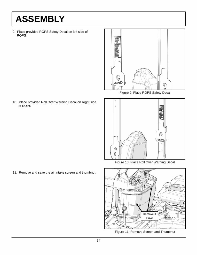
9. Place provided ROPS Safety Decal on left side of ROPS 10. Place provided Roll Over Warning Decal on Right side of ROPS 11. Remove and save the air intake screen and thumbnut.
Figure 11: Remove Screen and Thumbnut
Remove + Save
Figure 9: Place ROPS Safety Decal
Figure 10: Place Roll Over Warning Decal
ASSEMBLY
15
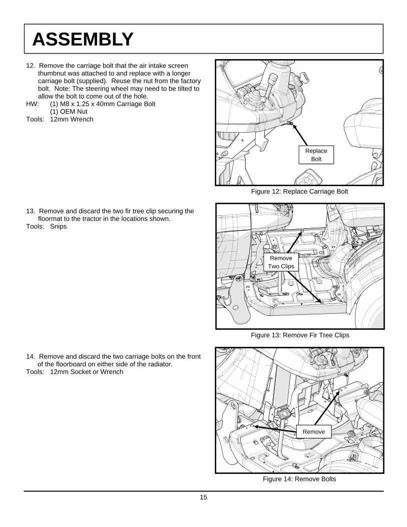
12. Remove the carriage bolt that the air intake screen thumbnut was attached to and replace with a longer carriage bolt (supplied). Reuse the nut from the factory bolt. Note: The steering wheel may need to be tilted to allow the bolt to come out of the hole. HW: (1) M8 x 1.25 x 40mm Carriage Bolt (1) OEM Nut Tools: 12mm Wrench 13. Remove and discard the two fir tree clip securing the floormat to the tractor in the locations shown. Tools: Snips 14. Remove and discard the two carriage bolts on the front of the floorboard on either side of the radiator. Tools: 12mm Socket or Wrench
Figure 14: Remove Bolts
Remove
Figure 13: Remove Fir Tree Clips
Remove Two Clips
Figure 12: Replace Carriage Bolt
Replace Bolt

ASSEMBLY
16
15. Disconnect the negative battery terminal. Tools: 13mm Wrench 16. Remove the nut from the positive battery terminal. Tools: 10mm Wrench 17. Locate the main cab power harness in the hardware box. Connect the ring terminal on the red wire to the stud on the positive battery terminal and reinstall the nut. Tools: 10mm Wrench 18. Connect the ring terminal on the black wire to the stud on the negative battery terminal and reinstall the nut. Reinstall the battery terminal onto the battery and tighten. Tools: 13mm Wrench 19. Locate the ignition source on the tractor. It is a female bullet terminal secured to the wire harness above the battery with blue electrical tape. Remove the tape to expose the terminal. 20. Connect the male bullet terminal on the end of the purple wire on the cab power harness to the terminal on the tractor. 21. Turn the key on without starting the tractor and check that the relay on the cab power harness clicks which would indicate power. 22. Route the plug on the end of the harness out along the right side of the radiator and down under the hood. Be sure to route the wire to avoid sharp edges and have clearance from the moving hood panel. 23. Remove the OEM bolts on the top of the rear facing seat bracket and slide the lower rear panel bracket in place on top of the OEM seat bracket. Reinstall the OEM seat bracket bolts. Tools: 12mm Socket
Figure 17: Install Red Wire
Figure 18: Install Black Wire
Figure 23: Install Lower Rear Panel Bracket
Reuse OEM Bolts
ASSEMBLY
17
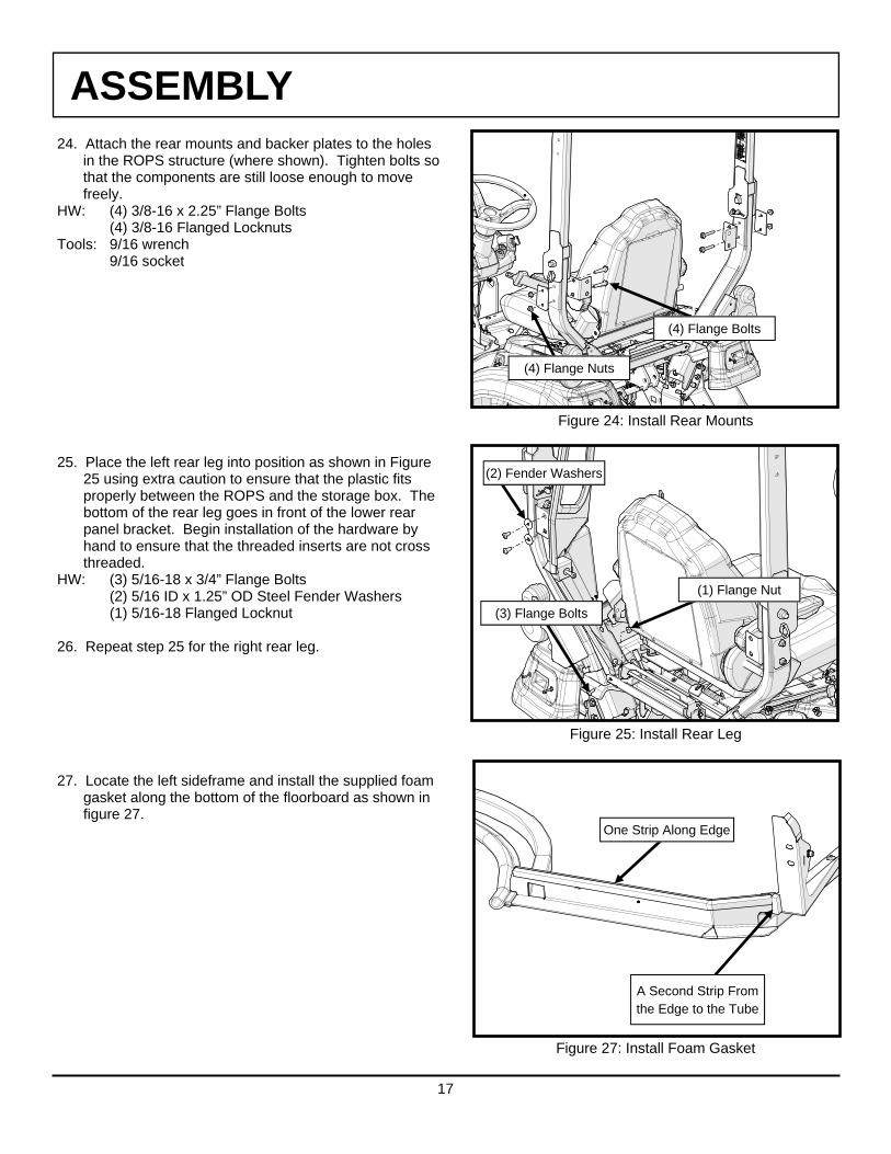
24. Attach the rear mounts and backer plates to the holes in the ROPS structure (where shown). Tighten bolts so that the components are still loose enough to move freely. HW: (4) 3/8-16 x 2.25” Flange Bolts (4) 3/8-16 Flanged Locknuts Tools: 9/16 wrench 9/16 socket 25. Place the left rear leg into position as shown in Figure 25 using extra caution to ensure that the plastic fits properly between the ROPS and the storage box. The bottom of the rear leg goes in front of the lower rear panel bracket. Begin installation of the hardware by hand to ensure that the threaded inserts are not cross threaded. HW: (3) 5/16-18 x 3/4” Flange Bolts (2) 5/16 ID x 1.25” OD Steel Fender Washers (1) 5/16-18 Flanged Locknut 26. Repeat step 25 for the right rear leg. 27. Locate the left sideframe and install the supplied foam gasket along the bottom of the floorboard as shown in figure 27.
Figure 24: Install Rear Mounts
(4) Flange Nuts
(4) Flange Bolts
Figure 27: Install Foam Gasket
One Strip Along Edge
A Second Strip From the Edge to the Tube
Figure 25: Install Rear Leg
(3) Flange Bolts
(2) Fender Washers
(1) Flange Nut

ASSEMBLY
18
28. With assistance, place the left sideframe into position. Be sure that the wire extending from the rear tube is positioned on the inside of the cab and is not pinched under the rubber. Lift the left 3” of rubber running along the top of the rear panel. Fasten through the tab at the top of the rear panel and leave finger tight. Re-install the rubber over both the rear panel and sideframe header. HW: (1) 5/16-18 x 3/4” Flange Bolt (1) 5/16-18 Flange Nut 29. Secure the front of the left frame to the front of the floorboard and leave finger tight. HW: (1) 5/16-18 x 3/4” Flange Bolt (1) 5/16-18 Flange Nut 30. Punch out the decal covering the outer hole in the floorboard and install the following bolt. Leave finger tight. HW: (1) 5/16-18 x 3/4” Flange Bolt (1) 5/16-18 Flange Nut 31. Install a bolt through the floorboard and leave finger tight. HW: (1) 1/4-20 x 3/4” Flange Bolt (1) 1/4-20 Flange Nut
Figure 31: Secure Sideframe to Floorboard
(1) Flange Nut
(1) Flange Bolt
Figure 29: Secure Front of Sideframe to Floorboard
(2) Flange Bolts
(2) Flange Nuts
Figure 28: Install Left Sideframe
(1) Flange Bolt
(1) Flange Nut

ASSEMBLY
19
32. Install bolts through the rear panel and into the rear of the sideframe. Leave finger tight. HW: (7) 5/16-18 x 3/4” Flange Bolt 33. Repeat steps 27-32 for the right sideframe 34. If installing a heater (BX4071), install at this time and
then proceed to step 37. If no heater will be installed, proceed to the following step.
35. With no heater being installed, remove the wire grommet from the hole on the right frame where shown and push the wire leads back into the tube. Install the supplied hole plug to cover the hole. Install a flange bolt into threaded inserts on both sides of the cab. HW: (2) 5/16-18 x 3/4” Flange Bolt (1) 11/16” Dome Plug 36. Install the cowl and attach to the sideframes. Leave the bolts finger tight. HW: (4) 5/16-18 x 3/4” Flange Bolt
Figure 36: Install the Cowl
(2) Flange Bolts
(2) Flange Bolts
Figure 32: Install Rear Panel Fasteners
(7) Flange Bolts
Figure 35: Replace Grommet with Hole Plug
Dome Plug
Flange Bolt

ASSEMBLY
20
37. Install the windshield support by sliding upwards along the front tubes. Leave the bolts finger tight. HW: (4) 5/16-18 x 3/4” Flange Bolt 38. Install the rear panel by hanging it on the upper pins at
the top of the rear legs and then engaging the lower quick release latches.
The quick release latches require (2) audible clicks to
be fully locked. Press the rear panel in from the outside in these locations to double click the latches. If unable to fully latch the rear panel, start by adjusting the quick release latch in or out as shown in Figure 38b. If you are still not able to properly latch the rear panel, adjust the pins found on the rear legs. Note that the lower pin adjustment is vertical (Fig. 38b) and the upper pin adjustment (Fig. 38c on next page) is horizontal.
Tools: 3/8 socket 1/2 socket 3/16 allen wrench
Figure 37: Install Windshield Support
Slide
(2) Flange Bolts
(2) Flange Bolts
Figure 38a: Install Rear Panel
Pin / Receiver
Quick Release Latch
Figure 38b: Align Rear Panel, Lower Pin Adj.
Quick Release Latch
Pin

ASSEMBLY
21
39. Tighten the cab bolts in the following order: Qty: 4 - 5/16 bolts through rear mounts and into rear panel. Note: Be sure that there is proper clearance between the bottom of the rear panel and the ROPS. If there is little clearance, use assistance to lift the rear of the cab and then tighten. Tools: 3/16 Allen Wrench Qty: 4 - Rear mount bolts through ROPS. Note: Be sure that there is proper clearance between the bottom of the rear panel and the ROPS. If there is little clearance, use assistance to lift the rear of the cab and then tighten. Tools: 9/16 Wrench 9/16 Socket Qty: 16 - Rear panel to sideframe bolts. Tools: 3/16 Allen Wrench 1/2” Socket Qty: 4 - Front floorboard bolts Tools: 3/16 Allen Wrench 1/2” Socket or Wrench Qty: 2 - Rear floorboard bolts Tools: 5/32 Allen Wrench 7/16” Socket Qty: 4 or 6 - Cowl/Heater bolts Tools: 3/16 Allen Wrench Qty: 4 - Windshield Support Bolts Tools: 3/16 Allen Wrench 40. With assistance, install the windshield. Use a spacer block under each hinge. Leave bolts finger tight. HW: (4) 5/16-18 x 1-1/2” Flat Head bolts (4) 5/16-18 Flange nuts
Figure 39b: Tighten Cab Bolts
5th: (2) 1/4” Bolts
6th: (4 or 6) 5/16” Bolts
7th: (4) 5/16” Bolts
Figure 39a: Tighten Cab Bolts
1st: (4) 5/16” Bolts
2nd: (4) 3/8” Bolts
4th: (4) 5/16” Bolts
3rd: (16) 5/16” Bolts
Figure 38c: Align Rear Panel, Upper Pin Adj.
Pin
Receiver

ASSEMBLY
22
Figure 41: Attach Windshield Latches
Figure 40: Install the Windshield
(4) Flange Nuts
(4) Flat Head Bolts
(2) Spacer Blocks
(4) Flange Bolts
(4) Flange Nuts
Figure 44: Connect Red Wire
White Wire
41. Attach the windshield latches to the sideframes and tighten. HW: (4) 1/4-20 x 3/4” Flange Bolts (4) 1/4-20 Flange Nuts Tools: 5/32 Allen Wrench 7/16” Wrench 42. Clamp the two windshield latches closed and then tighten the four windshield hinge bolts at this time. Caution: The windshield hinges are plastic components. Do not over tighten the 5/16-18 flat head screws. Torque to 7 ft.-lbs. max. Tools: #3 Phillips Screwdriver 1/2” Wrench 43. Install any of the following accessories at this time. BX4072 - Front Wiper BX4073 - Rear Wiper BX4074 - Front LED Lights BX4075 - Rear LED Lights F5314 - Interior Rear View Mirror 44. Connect the white wire extending from the top of the sideframe to the male portion of the piggyback terminal on the first circuit breaker. If no circuit breakers are installed, no connection is required.

ASSEMBLY
23
45. Connect the black wire with the push-on terminal to the ground strip. 46. Connect the weatherproof connector from the main power harness installed in steps 14-17 to the connector on the harness protruding from the bottom of the right sideframe. Be sure to route the harnesses to avoid sagging. Pull any excess wire back into the battery compartment and secure with cable ties. 47. Turn the key to the on position and test the function of the accessories at this time. 48. Install the left front roof mount. Tighten so that the fastener is snug and the top surface is in line with the curve of the rubber along the top edge of the sideframe. HW: (1) 1/4-20 x 5/8” Flange Bolt (3) 1/4 ID Nylon Washers (1) 1/4-20 Flange Nut Tools: 5/32 Allen Wrench 7/16” Socket 49. Repeat step 48 for right side.
Figure 48: Install Left Front Roof Mount
(1) Flange Nut
(1) Flange Bolt
(1) Nylon Washer
Figure 45: Connect Black Wire
Black Wire
Figure 46: Connect Weatherproof Connector
ASSEMBLY
24
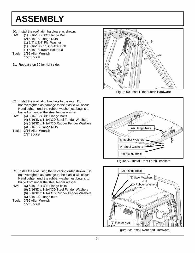
50. Install the roof latch hardware as shown. HW: (1) 5/16-18 x 3/4” Flange Bolt (2) 5/16-18 Flange Nuts (1) 1/4” x 3/4” Flat Washer (1) 5/16-18 x 1” Shoulder Bolt (1) 5/16-18 10mm Ball Stud Tools: 3/16 Allen Wrench 1/2” Socket 51. Repeat step 50 for right side. 52. Install the roof latch brackets to the roof. Do not overtighten as damage to the plastic will occur. Hand tighten until the rubber washer just begins to bulge from under the steel fender washer. HW: (4) 5/16-18 x 3/4” Flange Bolts (4) 5/16”ID x 1-1/4”OD Steel Fender Washers (4) 5/16”ID x 1-1/4”OD Rubber Fender Washers (4) 5/16-18 Flange Nuts Tools: 3/16 Allen Wrench 1/2” Socket 53. Install the roof using the fastening order shown. Do not overtighten as damage to the plastic will occur. Hand tighten until the rubber washer just begins to bulge from under the steel fender washer. HW: (6) 5/16-18 x 3/4” Flange bolts (6) 5/16”ID x 1-1/4”OD Steel Fender Washers (6) 5/16”ID x 1-1/4”OD Rubber Fender Washers (6) 5/16-18 Flange nuts Tools: 3/16 Allen Wrench 1/2” Socket
(2) Flange Bolts
(2) Steel Washers
(2) Rubber Washers
(2) Flange Nuts
Figure 53: Install Roof and Hardware
Figure 50: Install Roof Latch Hardware
Figure 52: Install Roof Latch Brackets
(4) Flange Bolts
(4) Steel Washers
(4) Rubber Washers
(4) Flange Nuts

ASSEMBLY
25
Figure 56: Install Air Intake Screen
Air Intake Screen
54. Of the four gas shocks in the hardware box, locate the 10lb/45N shocks (qty.: 2) for the roof. The other two shocks are 30lb/130N and are used later for the doors. Install the gas shocks for the roof with the shock body and quick release on the bottom and the sliding rod on the top. 55. Install a 7” piece of foam to the top of the floorboard and route it down under where the air intake screen will sit as in figure 55 (see the white dashed lines in the photo). Repeat for the right side. 56. Re-install the air intake screen, but do not use the OEM thumbnut yet.
Figure 54: Install Roof Gas Shocks
Shock Body Down
Foam
Figure 55: Foam Installation

ASSEMBLY
26
Figure 58: Route Front Flasher Light Harness
Cable Clamps
Cable Clamp
Cable Clamps
Figure 59: Connect Flasher Light Harness
Harness From Machine
Flasher Harness Rear Lights
57. Install the plastic air intake shroud HW: (6) 1/4-20 Thumbnuts (1) OEM Thumbnut 58. Route the front flasher light harnesses around the plastic panels (see the white dashed lines in the photo) using the cable clamps provided. Be sure the wires are close to the fenders as they are routed down and out of the cab so the seat springs clear them easily. 59. Connect the front flasher light harnesses to the existing rear lights. Connect Black to Black, Red to Red, and White to Black/White stripe.
Figure 57: Install Plastic Air Intake Shroud
(6) 1/4-20 Thumbnuts
(1) OEM Thumbnut

ASSEMBLY
27
Figure 61: Install The Doors
60. Remove factory carriage bolt and nut from the front left corner of the seat slider and discard. Install the seat limiting plate inside the seat slider track with (3) washers as spacers. HW: (1) 5/16-18 x 1” Carriage Bolt (3) 5/16”ID Steel Washers (1) 5/16-18 Flange Nut Tools: 1/2” Wrench 61. Install the doors and reconnect the gas shocks.
See door troubleshooting on page 34 for information about adjusting the door latches and hinges.
62. Using the newly supplied arm for the SMV sign, reattach the SMV sign sleeve removed in step 1.
Figure 62: Install New Arm For SMV Sign
(1) Flange Nut
(3) Washers
Seat Limiting Plate
(1) Carriage Bolt
Figure 60: Install The Seat Limiting Plate

ASSEMBLY
28
63. Replace SMV sign.
64. If installing a snow blower attachment with a manual chute rotation, replace the plug in the cowl with the supplied plastic split grommet.
HW: (1) Split Grommet
Figure 64: Install Split Grommet
(1) Split Grommet
Figure 63: Install SMV Sign
29
OPERATION
WARNING REQUIRED BEFORE OPERATION
1. Read and understand this entire manual and any other publications for the equipment being operated. 2. Ensure that the surrounding area is clear and that personnel are positioned away from the area where engagement
and disengagement of attachments will occur 3. Always shut off engine when leaving the operator’s area to perform any portion of the listed procedures
POP-UP ROOF
The BX4090 cab features a hinged and gas shock supported roof. This feature allows for backhoe operation as well as provides additional ventilation.
To operate the roof, press up on the yellow lever on the quick release latches. It may help to pull down slightly on the grab handles while releasing the latches.
To lock the roof in the down position, simply pull down on the grab handles until each latch has double clicked.
Note: Pull down on each handle at the same time to ensure accurate positioning of the latches.
REMOVABLE REAR PANEL
The BX4090 cab features a removable rear panel that allows access when using the backhoe.
To remove the rear panel:
1. First raise the hinged roof following the instructions above.
2. Release the two latches towards the bottom of the rear panel. It may be necessary to push out on the lower section of the rear panel to prevent the latches from re-engaging.
3. From the outside of the cab, lift up on the rear panel and pull towards the backhoe.
Store the rear panel in a safe location to prevent damage.
To reinstall the rear panel, align the slots at the top with the pins on the rear legs and drop into place. Push in on the lower corners of the rear panel to ensure double latching of the quick release latches.
Pop-Up Roof
Removable Rear Panel
Quick Release Latch
30
Pop-Out Windshield
Lift-Off Doors
Pop-Open Front Windows
OPERATION
WARNING REQUIRED BEFORE OPERATION
1. Read and understand this entire manual and any other publications for the equipment being operated. 2. Ensure that the surrounding area is clear and that personnel are positioned away from the area where engagement
and disengagement of attachments will occur 3. Always shut off engine when leaving the operator’s area to perform any portion of the listed procedures
POP-OUT WINDSHIELD
The BX4090 cab comes equipped with a pop-out windshield for ventilation. To open the windshield, simply lift up on both of the pop-out latches and rotate until the latches rest in the over-center position.
LIFT-OFF DOORS
For added ventilation, the doors on the BX4090 cab lift off in seconds without tools.
To lift off:
1. First raise the hinged roof following the instructions on the previous page.
2. Stabilize the door and take pressure off the gas shock. Disconnect the gas shock from the sideframe by sliding the red release slide away from the shock body and gently pulling the shock off the ball stud.
3. Rotate the door 90° to the sideframe and lift. Also, remove the hinge washers and store in a plastic bag. Store the doors in a safe location to prevent damage.
POP-OPEN FRONT WINDOWS
The BX4090 cab has front lower windows that open for access to the machine loader attachment levers. To open the windows, release the latches and open. The window hinges are designed to stop the windows from swinging open too far and contacting the doors. When closing, ensure the latches double click to properly seal the windows back to the plastic shroud.

31
Auxiliary Radiator Intake Cover
OPERATION
WARNING REQUIRED BEFORE OPERATION
1. Read and understand this entire manual and any other publications for the equipment being operated. 2. Ensure that the surrounding area is clear and that personnel are positioned away from the area where engagement
and disengagement of attachments will occur 3. Always shut off engine when leaving the operator’s area to perform any portion of the listed procedures
AUXILIARY RADIATOR INTAKE COVER
The BX4090 cab has a removable auxiliary radiator intake cover that should be removed when not operating the machine in cold weather conditions in order to prevent the machine from potentially overheating. Four thumb nuts hold the cover in place, and the cover can be stored inside the seat-back storage compartment, if equipped.
REMOVABLE RADIATOR INTAKE SHROUD
The BX4090 cab has a removable radiator intake shroud that provides access to the under-dash battery area during machine servicing. Remove the six small thumb nuts as well as the one larger OEM knob and gently pull the shroud towards the back. Re-installation is the opposite, and it is easiest to align the lower studs first, then tilt the top of the shroud forward onto the remaining studs.
SEAT RECLINING WARNING
The rear panel in the BX4090 cab is as far back as it could be placed while maintaining clearance for various BX tractor options. A seat travel limiting plate has been installed to prevent the seat bottom from sliding too far back and contacting the rear panel, however it is still possible for the seat back to be reclined into the rear panel. Care must be taken to ensure that the seat is positioned so that it does not contact the cab in order to prevent possible damage.
Removable Radiator Intake Shroud
OEM Knob
Thumb Nuts

32
CARE AND MAINTENANCE: Check and tighten all hardware after 20 hours of operation. Periodically inspect and tighten hardware for the remainder of the unit’s service life. Keep the components clean in order to prevent dust and dirt from form-ing an unattractive film. The life of your cab components depend upon following these care procedures: 1. NEVER USE AN ABRASIVE DETERGENT / VEHICLE CLEANER OR A WIRE BRISTLED BRUSH. Do
not use any CITRUS BASED CLEANERS such as orange or lemon. 2. NEVER USE AN ALCOHOL-BASED PRODUCT FOR CLEANING THE PLASTICS.
Do not use WINDEX, GLASS PLUS, FANTASTIC, etc. Use of these products will result in deterioration of the plastics.
3. Clean the enclosure surfaces thoroughly with warm soapy water and a COTTON cloth or chamois. Be sure to use mild soap, specifically a dish liquid or equivalent. Clean in a light circular motion for best results.
4. Remove grease and oil with mineral spirits and a COTTON cloth or chamois.
MAINTENANCE

33
CHECK LIST FOR INSPECTION AFTER ASSEMBLY
Inspector: Date Completed:
Tractor Model: Serial Number:
Classification Inspection Items Result
Assembly 1. Check for proper tightening of all fasteners
2. Check for proper wire connections
Operation 1. Check to see if relay clicks on/off with ignition
2. Check to see if doors have two audible clicks when latching
3. Check that front and rear flashers work properly

34
TROUBLESHOOTING
Condition Possible Solution
Doors do not double click at latch Adjust door striker pin up, down, in, or out depending on need.
If striker pin adjustment is not enough, loosen the bolts holding the door hinges, locate door where desired, and re-tighten hinges
Flasher lights are not working properly Check electrical connections at rear lights. Note: Be sure that the insulation on the male bullet on the OEM tractor light is cut back enough to provide proper connection
Check to be sure front light wire is properly grounded by loosening the nut on the light and re-tightening. The light grounds through the threaded stud.
Accessories are not working properly Check to be sure that the relay is turning on/off with the ignition key.
Confirm that the main fuse at the battery is good. Check to be sure the plug at the bottom of the right frame is
connected to the machine harness Remove the roof and check the positive and negative
connections for the main power harness. Negative should ground to the ground strip and positive should connect to the accessory circuit breaker
Door latch and striker pin do not line up vertically. Loosen striker pin and move up or down using (2) 3/4” wrenches to adjust.
Door latch and striker pin do not line up horizontally. Loosen (2) 1/4-20 hex flange screws between latch and door. Move interior door latch forward or backward. Retighten.

PARTS BREAKDOWN
35
ITEM #: PART NUMBER: CODE NUMBER: QTY/KIT: DESCRIPTION:
1 77700-08526 102-00012 1 WINDSHIELD ASSEMBLY
2 70000-01040 9PH007 1 HINGE ASSY, STD WINDSHIELD KIT
3 77700-08560 9WL06 1 LATCH, POP-OUT, SINGLE ARM, 3IN OPENING
4 70000-01252 9PR38 169” 3/4" SIDE BULB, 1/4" GRIP WITH 2 WIPERS
5 70000-01015 9BLK01 1 WINDSHIELD HINGE BLOCK SPACER, TALL STYLE, 3/4" THICK
6 77700-08538 SM-00447 1 SEAT TRAVEL LIMITING PLATE
7 77700-08528 105-00009 1 COWL ASSEMBLY
8 77700-08557 9GR14 1 RUBBER GROMMET, .75/WEB ID, 1.4375 OD, .094 GW, 1.00 GD
9 70000-01397 9PRO2 37” 5/8" STD BULB, 1/16" GRIP
10 77700-08541 9PR53 48” ARCH PSA RUBBER, .20WDX.15TALL
11 77700-08534 HWK-00037 1 HARDWARE KIT
N.S. 70000-01216 9DL01H 2 KEYS, CAB DOOR
N.S. 77700-05439 KF2-RWH 1 WIRE HARNESS, RELAY, KF2
N.S. 77700-08572 IM-BX4090 1 INSTALLATION INSTRUCTIONS, KBX80 TLB
3
2
4
HARDWARE KIT
2X—BALL STUD, 10MM, 5/16-18
2X—SHOULDER SCREW, 3/8” DIA X 1LG
1X—CARRIAGE BOLT, 5/16-18 X 1LG
1X—CARRIAGE BOLT, M8X1.25 X 40LG
4X—SCREW, FLAT HEAD, 5/16-18 X 1.5LG
3X—SCREW, PAN HEAD, #10-32 X 5/8LG
2X—SCREW, BUTTON HEAD FLANGE, 1/4-20 X 5/8LG
6X—SCREW, BUTTON HEAD FLANGE, 1/4-20 X 3/4LG
44X—SCREW, BUTTON HEAD FLANGE, 5/16-18 X 3/4LG
4X—SCREW, HEX FLANGE, 3/8-16 X 3/4LG
4X—SCREW, HEX FLANGE, 3/8-16 X 2-1/4LG
2X—SCREW, HEX FLANGE, M10X1.25 X 25LG
2X—STEEL WASHER, USS, 1/4” ID X 3/4” OD
3X—STEEL WASHER, SAE, 5/16” ID
10X—STEEL FENDER WASHER, 5/16” ID X 1-1/4” OD
2X—NYLON WASHER, 5/16” ID X 11/16” OD
6X—RUBBER WASHER, 5/16” ID X 1-1/4” OD
3X—NYLON WASHER, #10 ID X 3/8” OD
3X—NUT, HEX FLANGE, NYLON INSERT, #10-32
8X—NUT, HEX FLANGE, NYLON INSERT, 1/4-20
23X—NUT, HEX FLANGE, NYLON INSERT, 5/16-18
8X—NUT, HEX FLANGE, NYLON INSERT, 3/8-16
6X—NUT, THUMB, 1/4-20
1 11
9
8 10
7
6 5
N.S. = Not Shown

PARTS BREAKDOWN
36
ITEM #: PART NUMBER: CODE NUMBER: QTY/KIT: DESCRIPTION:
12 77700-08527 103-00007 1 WINDSHIELD SUPPORT ASSEMBLY
13 77700-01480 9DP01 1 DOME PLUG, 7/16", HEYCO #2633
14 77700-08558 9DP02 1 DOME PLUG, 1", HEYCO #2713
15 77700-08559 9DP10 1 DOME PLUG, 3/8", HEYCO #2617
16 77700-05150 9DP16 1 HOLE PLUG, .75" X 1/8" GRIP, HEYCO #2683
17 77700-05153 9VH2-01 1 HOLE PLUG FOR V-SERIES BK CARLING SWITCH
18 70000-01397 9PRO2 37” 5/8" STD BULB, 1/16" GRIP
19 77700-08541 9PR53 48” ARCH PSA RUBBER, .20WDX.15TALL
20 77700-08533 111-00008 1 RADIATOR SHROUD, PLASTIC
21 77700-08540 111-00009 1 AUXILIARY RADIATOR INTAKE COVER
22 77700-08542 9GL-00026 1 RADIATOR SHROUD WINDOW, LEFT
23 77700-08543 9GL-00027 1 RADIATOR SHROUD WINDOW, RIGHT
24 77700-08544 P-00026 1 RADIATOR SHROUD, MOLDED PLASTIC
25 77700-01021 9YR-LL 1 LATCH, EBERHARD, LEFT (8-24OU)
9YR-LR 1 LATCH, EBERHARD, RIGHT (8-240U)
26 70000-01252 9PR38 169” 3/4" SIDE BULB, 1/4" GRIP WITH 2 WIPERS
21a 77700-09080 9DL-209 1 DECAL, CAUTION, AUXILIARY RADIATOR INTAKE INFORMATION
12 20
18
19 16
15 14
17
13
26
25
25
22
23
21
24
21a

PARTS BREAKDOWN
37
ITEM #: PART NUMBER: CODE NUMBER: QTY/KIT: DESCRIPTION:
27 77700-08562 108-00006-L 1 REAR LEG ASSEMBLY, TLB, LEFT
28 77700-08563 108-00006-R 1 REAR LEG ASSEMBLY, TLB, RIGHT
29 77700-08564 9GL-00023 1 REAR LEG WINDOW, TLB
30 77700-08645 P-00023 1 STORAGE BOX SHROUD, TLB, LEFT, MOLDED PLASTIC, BX80
31 77700-08646 P-00024 1 FUEL FILLER SHROUD, TLB, RIGHT, MOLDED PLASTIC, BX80
32 77700-08559 9DP10 1 DOME PLUG, 3/8", HEYCO #2617, BLACK
33 77700-08648 9DP11 1 DOME PLUG, 1/2", HEYCO #2643, BLACK
34 70000-01050 9PRO1 220” TRIM LOK, STD, 1/16"-1/8" GRIP
35 70000-01397 9PRO2 37” 5/8" STD BULB, 1/16" GRIP
36 77700-00279 9PR10 110” WINDOW RUBBER, 14-16GA STEEL, .18-.28 WINDOW THICKNESS
37 77700-05144 9PR19 72” 1" ROUND BULB, 1/16" GRIP
38 77700-08541 9PR53 48” ARCH PSA RUBBER, .20WDX.15TALL
39 77700-08573 113-00042 1 RP LOWER FILLER PLATE ASSY,TLB
40 77700-08570 SM-00390 1 ROPS BRACKET, TLB
41 77700-08537 SM-00442 1 ANCHOR PLATE, ROPS
42 77700-08567 SM-00443 1 SMV BRACKET, BX80
40
28 27 37
29
36
38
31
37
29
36
38
30
34 34
33
32
33
32
35 35
39 41 42

PARTS BREAKDOWN
38
53
54 55
ITEM #: PART NUMBER: CODE NUMBER: QTY/KIT: DESCRIPTION:
43 77700-08561 106-00012 1 REAR PANEL ASSEMBLY, BX80, TLB
44 77700-08565 9GL-00024 1 REAR PANEL GLASS, TLB
45 77700-08566 9GL-00025 1 REAR PANEL GLASS, LOWER, TLB
46 70000-01021 9GH01 1 GRAB HANDLE (PLASTIC)
47 77700-01482 9PI01 1 POLY INSERT 1", 14-20 GA BLK, MATTE ,INSERT FINS .94/.95
49 77700-01021 9YR-LL 1 LATCH, EBERHARD, LEFT (8-24OU)
9YR-LR 1 LATCH, EBERHARD, RIGHT (8-240U)
50 70000-01397 9PRO2 37” 5/8" STD BULB, 1/16" GRIP
51 77700-00279 9PR10 110” WINDOW RUBBER, 14-16GA STEEL, .18-.28 WINDOW THICKNESS
52 77700-08647 9PR27 120” 5/8" O/S SIDE BULB, 1/16" GRIP (ROUND BULB)
58 77700-05202 9GS10Q 1 GAS SPRING, 20 EXT, 12 COMP, 10 LBS, QD ENDS (FOR ROOF)
53 77700-08525 101-00009 1 ROOF ASSEMBLY
54 77700-08535 SM-00298-L 1 ROOF PIVOT BRACKET, LEFT
55 77700-08536 SM-00298-R 1 ROOF PIVOT BRACKET, RIGHT
56 77700-08568 113-00043-L 1 ROOF LATCH ASSEMBLY, LEFT, BX80, TLB
48 77700-01483 9PI02 1 POLY INSERT 3/4", 14-20 GA BLK, MATTE FINISH, INSERT FINS 0.69
57 77700-08569 113-00043-R 1 ROOF LATCH ASSEMBLY, RIGHT, BX80, TLB
58 43
57 56
49 49
45
44
49
49
48
47
50
51
52
46

PARTS BREAKDOWN
39
ITEM #: PART NUMBER: CODE NUMBER: QTY/KIT: DESCRIPTION:
59 77700-08531 109-00006-L 1 SIDEFRAME ASSEMBLY, LEFT
60 77700-08532 109-00006-R 1 SIDEFRAME ASSEMBLY, RIGHT
62 77700-08548 9DP05 1 DOME PLUG, 11/16", HEYCO #2673
63 77700-05457 9HR03 1 RUBBER GROMMET, .4375IDx.125GW, x.6875GDx.9375OD (RPD G3102)
64 77700-08549 9HR05 1 RUBBER GROMMET, .5313IDx.125GW x.6875GDx.8125OD (RPD 3095)
65 70000-01024 9GS02A 1 BALL STUD, 10MM, 5/16-18, HB
66 77700-08644 114-00006 1 FRONT FLASHER, 4" ROUND, POST MOUNT, AMBER/AMBER
67 77700-05253 9PHW010-W 1 HINGE WASHER, WELD-ON, BRASS, (.635"OD X .41"ID X .08"THK)
68 70000-01050 9PRO1 220” TRIM LOK, STD, 1/16"-1/8" GRIP
69 70000-01397 9PRO2 37” 5/8" STD BULB, 1/16" GRIP
70 77700-05144 9PR19 72” 1" ROUND BULB, 1/16" GRIP
71 77700-08541 9PR53 48” ARCH PSA RUBBER, .20WDX.15TALL
N.S. 77700-05134 9PR43 92” 1/2" X 9/16" X RUBBER FOAM WEATHERSEAL (FROST KING R930H)
N.S. 77700-08545 WH-00033 1 WIRING HARNESS, KBX80
N.S. 77700-08546 WH-00034 1 WIRING HARNESS, FRONT FLASHERS TO REAR LIGHTS, KBX80
61 77700-08547 9DL01D-H 1 STRIKER BOLT, HARD, 42MM OAL 450-600 HV1, 170-200 HB 30, HB
60 59
61
64
62
63
65
66
66
67
68
69 69
70
70
71
71
N.S. = Not Shown

PARTS BREAKDOWN
40
87
ITEM #: PART NUMBER: CODE NUMBER: QTY/KIT: DESCRIPTION:
72 77700-08529 107-00013-L 1 DOOR ASSEMBLY, LEFT
73 77700-08530 107-00013-R 1 DOOR ASSEMBLY, RIGHT
75 77700-08554 9SW-00009-L 1 SLIDING WINDOW, FS-105, 29.56 X 24.62 X 22.55 X 28.76
76 77700-08551 9SW-00009-R 1 SLIDING WINDOW, FS-105, 29.56 X 24.62 X 22.55 X 28.76
77 77700-08555 PL-00010-L 1 HINGE SLEEVE ASSY, W-O, SHORT, KUB-DGRAY, LEFT
78 77700-08552 PL-00010-R 1 HINGE SLEEVE ASSY, W-O, SHORT, KUB-DGRAY, RIGHT
79 77700-08556 PL-00011-L 1 HINGE SLEEVE ASSY, W-O, LONG, KUB-DGRAY, LEFT
80 77700-08553 PL-00011-R 1 HINGE SLEEVE ASSY, W-O, LONG, KUB-DGRAY, RIGHT
81 70000-01016 9DL01A 1 DOOR LATCH, STD, LEFT (USED ON RIGHT SUICIDE DOORS)
82 70000-01017 9DL01B 1 DOOR LATCH, STD, RIGHT (USED ON LEFT SUICIDE DOORS)
83 70000-01018 9DL01C 1 DOOR HANDLE, OUTSIDE, PLASTIC (ROTARY LATCH)
84 70000-01024 9GS02A 1 BALL STUD, 10MM, 5/16-18, HB
85 77700-00279 9PR10 110” WINDOW RUBBER, 14-16GA STEEL, .18-.28 WINDOW THICKNESS
86 70000-01401 9PR17 169” 3/4" SIDE BULB, 1/16" GRIP
87 77700-08539 9GS12Q 1 GAS SPRING, 20" EXT, 12" COMP, 30 LBS, QD END (FOR DOORS)
74 77700-08550 9GL-00028 1 DOOR WINDOW, LOWER, GLASS
73 72
74
74
83
75 76
77
79
78
80
81 82 84
85 85 86 86

41
TORQUE SPECIFICATION TABLE