Embed Size (px)
Citation preview

1Peter Bechtold
Institute of Photonic Technologies, Univ. Erlangen, Germany
In cooperation with NTT AT Corp. and Univ. Twente
Experimental setup
= 1070 nmPmax = 50 W2w0 = 1.37 mm = 1.2 mrad
f = 100 mm
f = -50 mm
On KTN surface:2wf = 0.50 mm*
or 0.22 mm
Coherent LM-45 HTDPower measurement
Coherent Lasercam HRBeam profile measurement
*: wf = 0.50 mm is achieved with slightly different setup (telescope before mirror)
Date: 09.01.2015 to 12.01.2015 Crystal: AOXB19-11-70 Laser power loss in KTN (reflection, absorption): 2.4% +/- 0.7% (N = 7) Laser power loss in wedge attenuator: 7.7% +/- 0.5% (N = 7) Laser power incident on KTN crystal = 111% Measured laser power
Metrolux ML2300Wedge attenuator

2Peter Bechtold
Institute of Photonic Technologies, Univ. Erlangen, Germany
In cooperation with NTT AT Corp. and Univ. Twente
Beam profile and TEC PWM duty cycle references
1 mm
Camera in position of first KTN surface
Setup for 2wf = 0.50 mm
Camera in measurement position: 280 mm behind first KTN surface (2w = 0.96 mm)
Setup for 2wf = 0.22 mm
Camera in position of first KTN surface
Camera in measurement position: 250 mm behind first KTN surface (2w = 1.37 mm)
TEC PWM duty cycle:Measured by detecting radiation close to TEC cablef = 14 kHzDuty cycle at room temperature: ~ 6.2%
1 mm

3Peter Bechtold
Institute of Photonic Technologies, Univ. Erlangen, Germany
In cooperation with NTT AT Corp. and Univ. Twente
Experiment I: No HV UV LED switched on for 10 sec prior to measurements Pm: Average power incident on KTN 2wf = 0.50 mm
Pm = 2.0 W 7.6 W 18.9 W 41.3 W 50.4 WTEC duty = 6.1% 6.0% 5.6% 4.8% 4.4%
No unexpected beam deformation (comparable to beam without KTN) TEC duty decreases linearly with increasing laser power: Constant, linear absorption in KTN
1 mm

4Peter Bechtold
Institute of Photonic Technologies, Univ. Erlangen, Germany
In cooperation with NTT AT Corp. and Univ. Twente
Experiment II: Constant HV UV LED switched on for 10 sec prior to Precharges Precharges: -200 V 10 sec and +300 V 10 sec DC Offset: -240 V 2wf = 0.50 mm
Pm = 2.0 W 7.6 W 18.8 W 40.7 WTEC duty = 6.0% 5.8% 5.3% 4.6%Defl. angle = 13.0 mrad 12.4 mrad 11.8 mrad 11.0 mrad
Less deflection with increasing laser power (KTN temperature constant at 26.0°C)
1 mm

5Peter Bechtold
Institute of Photonic Technologies, Univ. Erlangen, Germany
In cooperation with NTT AT Corp. and Univ. Twente
Experiment III: AC HV 0.50 mm
UV LED switched on for 10 sec prior to Precharges
Precharges: -200 V 10 secand +300 V 10 sec
DC Offset: -240 V AC: 1 kHz, 360 Vpp 2wf = 0.50 mm
Again, reduced deflection angle for increasing laser power
Varying energy distribution with increasing laser power
Pm = 2.0 W 7.6 W 18.9 W 50.3 W 50.2 WTEC duty = 5.8% 5.4% 4.8% 3.7% 3.4%Defl. angle amplitude = 20.2 mrad 18.7 mrad 18.1 mrad 15.8 mrad 21.3 mrad
500 Vpp
2 mm

6Peter Bechtold
Institute of Photonic Technologies, Univ. Erlangen, Germany
In cooperation with NTT AT Corp. and Univ. Twente
Experiment IV: AC HV 0.22 mm UV LED switched on for 10 sec prior to Precharges Precharges: -200 V 10 sec and +300 V 10 sec DC Offset: -240 V AC: 1 kHz, 360 Vpp 2wf = 0.22 mm
Much stronger deflection anglereduction at increasing laserpower due to smaller beamdiameter
Changing energy distributionwith increasing laser power
Increased impact of higherVpp at max. laser power
Pm = 1.9 W 7.4 W 18.2 W 48.8 W 48.8 WTEC duty = 4.7% 4.6% 4.2% 3.0% 2.7%Defl. angle amplitude = 18.7 mrad 16.8 mrad 11.9 mrad ~1.5 mrad 22.7 mrad
600 Vpp
2 mm

7Peter Bechtold
Institute of Photonic Technologies, Univ. Erlangen, Germany
In cooperation with NTT AT Corp. and Univ. Twente
Exemplary demonstrations
1 mm 5 mrad
Pm = 41.1 WTEC duty 3.6%Defl. AngleAmplitude: 19.6 mrad
1 kHz trianglewaveform500 Vpp
Pm = 22.3 WTEC duty 3.7%Defl. AngleAmplitude: 23.0 mrad
1 kHz rect.waveform480 Vpp
Contrast ratio of rectangle waveform: 5.5:1

8Peter Bechtold
Institute of Photonic Technologies, Univ. Erlangen, Germany
In cooperation with NTT AT Corp. and Univ. Twente
TEC duty cycle over average power
TEC duty cycle linearly dependent on average power
Will cross x-axis at approximately130 W … 180 W
Increased TEC current at room temperature will allow for higher laser powers
Active cooling of the surroundings may be beneficial (i.e. lowering TEC duty cycle at 0 W laser power)

9Peter Bechtold
Institute of Photonic Technologies, Univ. Erlangen, Germany
In cooperation with NTT AT Corp. and Univ. Twente
Deflection per volt over average laser power
Deflection decreasing with increasing laser power
Crystal is heated up locally, partly loosing ability to deflect the beam (i.e. lateral temperature gradient)
Severe impact of decreased beam diameter and increased intensity
May be compensated by higher deflection voltage (is not the case for lower intensity), compare page 6

10Peter Bechtold
Institute of Photonic Technologies, Univ. Erlangen, Germany
In cooperation with NTT AT Corp. and Univ. Twente
Deflection per volt over laser intensity
Beam deflection angle reduction due to lateral temperature gradient is dependent on laser intensity
Effect may be counteracted by increasing the voltage for higher intensities

11Peter Bechtold
Institute of Photonic Technologies, Univ. Erlangen, Germany
In cooperation with NTT AT Corp. and Univ. Twente
KTN crystal topographyOptical microscope Confocal microscope
There was no observable damage induced during any of the experiments
The crystal is suitable for cw intensities of at least 2.6 105 W/cm² (wavelength 1070 nm)
Topography before experiments
Topography after experiments
12Peter Bechtold
Institute of Photonic Technologies, Univ. Erlangen, Germany
In cooperation with NTT AT Corp. and Univ. Twente
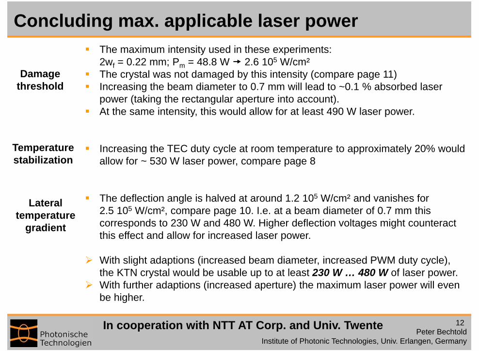
Concluding max. applicable laser power The maximum intensity used in these experiments:
2wf = 0.22 mm; Pm = 48.8 W 2.6 105 W/cm² The crystal was not damaged by this intensity (compare page 11) Increasing the beam diameter to 0.7 mm will lead to ~0.1 % absorbed laser
power (taking the rectangular aperture into account). At the same intensity, this would allow for at least 490 W laser power.
Increasing the TEC duty cycle at room temperature to approximately 20% would allow for ~ 530 W laser power, compare page 8
The deflection angle is halved at around 1.2 105 W/cm² and vanishes for 2.5 105 W/cm², compare page 10. I.e. at a beam diameter of 0.7 mm this corresponds to 230 W and 480 W. Higher deflection voltages might counteract this effect and allow for increased laser power.
With slight adaptions (increased beam diameter, increased PWM duty cycle), the KTN crystal would be usable up to at least 230 W … 480 W of laser power.
With further adaptions (increased aperture) the maximum laser power will even be higher.
Damagethreshold
Temperaturestabilization
Lateraltemperature
gradient

13Peter Bechtold
Institute of Photonic Technologies, Univ. Erlangen, Germany
In cooperation with NTT AT Corp. and Univ. Twente
Further discussion
230 W … 460 W of laser power are enough for efficient welding and selective laser melting.
The varying beam profile deformation, varying energy distribution and decreasing deflection angle (amplitude) heavily suggest that a closed-loop control will be needed for deflecting high-power cw laser beam with KTN scanners in a controlled manner, compare results on pages 5 and 6.
Exemplary results on page 7 show the application as semi-simultaneous beam shaping device and semi-simultaneous beam divider.


![Ktn pump presentation march 14 [compatibility mode]](https://img.dokumen.tips/doc/110x75/53f4af848d7f728e318b48e1/ktn-pump-presentation-march-14-compatibility-mode.jpg)