Embed Size (px)
Citation preview
kewtechcorp.com
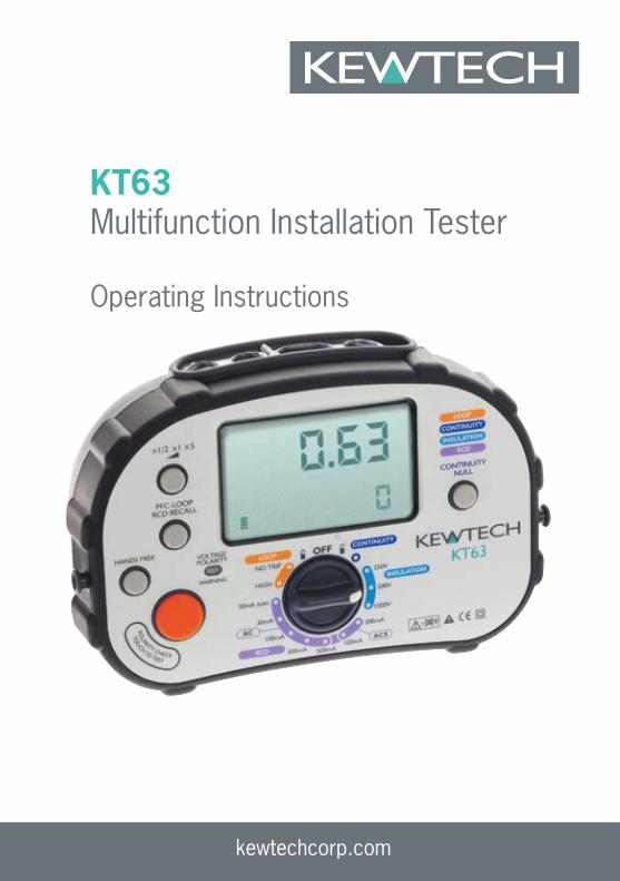
KT63 Multifunction Installation Tester
Operating Instructions

kewtechcorp.com
2
kewtechcorp.com
3
kewtechcorp.com
IndexSafety information and explanation of symbols used ......................3Features of the KT63 ....................................................................5
Special Polarity Test Function. ........................................................... 6Audible tones ...............................................................................7Overview of the switches and LCD ..............................................8Test lead inputs ............................................................................9Continuity Test Function ..............................................................10
Continuity Test Procedure ................................................................ 10Lead Nulling ................................................................................... 10Hands Free Continuity Testing .......................................................... 11
Insulation Test Function ..............................................................12Insulation Test Procedure ................................................................ 12Hands Free Insulation Testing .......................................................... 13
Loop Test functions ....................................................................14High Current mode ......................................................................... 14No Trip Mode ................................................................................. 14PFC/PSC ....................................................................................... 15Test lead configuration .................................................................... 15Lead configuration for No-Trip testing ............................................... 16Lead configuration for High current 2-wire testing ............................. 16Loop Test Procedures ..................................................................... 17No Trip Loop test (Zs) ..................................................................... 17High current test (Ze) ...................................................................... 18Hands Free Loop testing ................................................................. 18
RCD Test Function ......................................................................19Ramp test ...................................................................................... 20Sinusoidal polarity (the 0° or 180° test) ............................................ 20RCD test procedure ........................................................................ 21User selected test .......................................................................... 2130mA Automatic test ...................................................................... 22Ramp test ...................................................................................... 22
Specifications and tolerances .....................................................23Continuity Test Range Accuracy ....................................................... 23Insulation Test Range Accuracy ........................................................ 23Insulation Output Voltage ................................................................. 23Loop Test Range Accuracy .............................................................. 23RCD Test Range Accuracy ............................................................... 24
Safety information and explanation of symbols used
Because the KT63 is a multi function tester used for testing both live and dead circuits there are different safety issues that apply to the individual functions. Before using your KT63 please read these instructions paying particular attention to the general safety warnings below and those at the start of each section.
Before using the tester check the case and the test leads for damage.
If any damage is noticed the unit should be withdrawn from service and returned to Kewtech for repair.
It is important for safety that only one set of leads can be fitted at a time. In the unlikely event that the interlock cover is damaged the tester should be withdrawn from service and returned to Kewtech for repair
Caution read this manual for safety information
The Continuity and Insulation functions are rated at 500V Category III
The Loop and RCD functions are rated at 300V Category IV
When installing batteries observe correct polarity do not mix old and new batteries - Dispose of used batteries in accordance with local regulations – Never incinerate batteries.
Do not use this tester in a manner other than that described in this booklet.
To clean the tester wipe with a damp cloth with a mild soap solution taking care not to allow water ingress into the input terminals. Do not use solvents and do not immerse. Allow the tester to fully dry before use.
The KT 63 is fuse protected against damage by accidental connection to an over-voltage supply. The fuse is located inside the battery compartment and can be accessed by removing the two small battery cover retaining screws on the back of the case. Always ensure that test leads are disconnected before removing the battery cover.
kewtechcorp.com
4
kewtechcorp.com
5
kewtechcorp.com
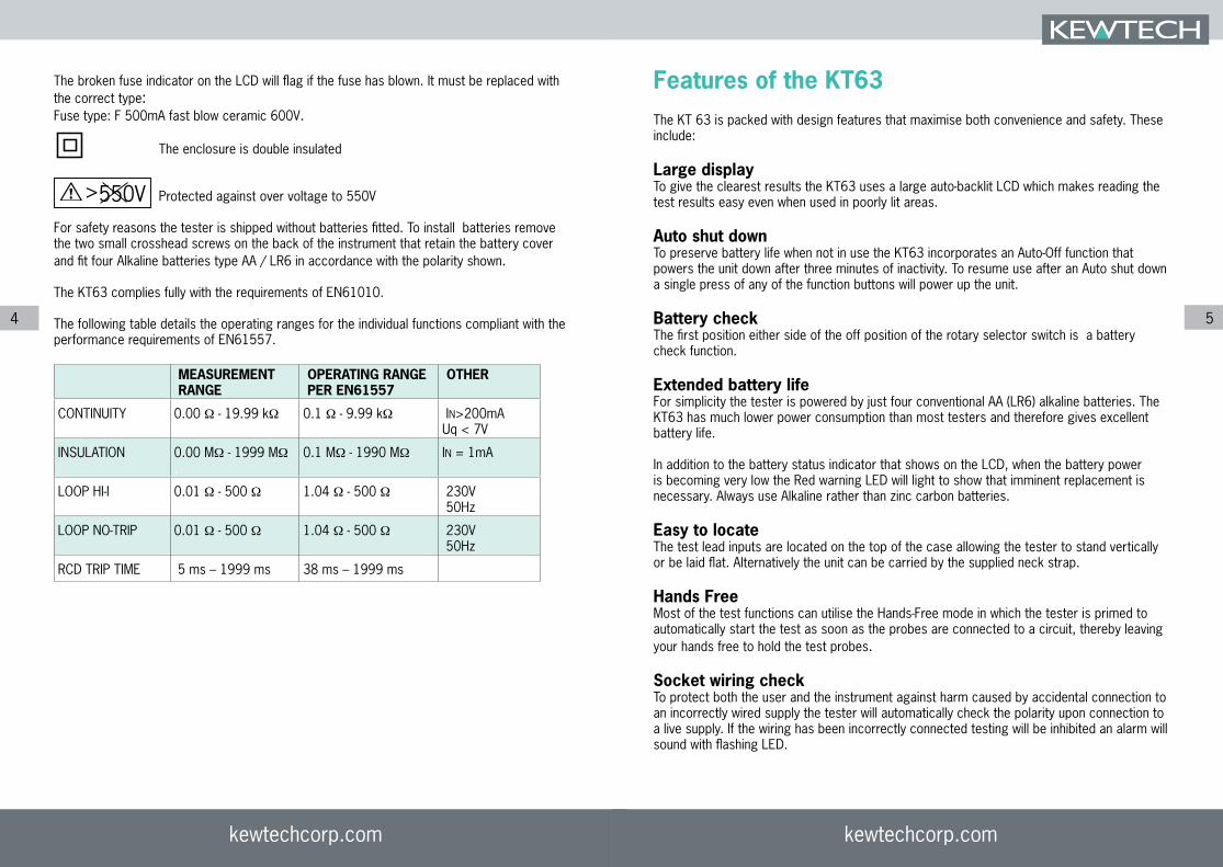
The broken fuse indicator on the LCD will flag if the fuse has blown. It must be replaced with the correct type:Fuse type: F 500mA fast blow ceramic 600V.
The enclosure is double insulated
Protected against over voltage to 550V
For safety reasons the tester is shipped without batteries fitted. To install batteries remove the two small crosshead screws on the back of the instrument that retain the battery cover and fit four Alkaline batteries type AA / LR6 in accordance with the polarity shown.
The KT63 complies fully with the requirements of EN61010.
The following table details the operating ranges for the individual functions compliant with the performance requirements of EN61557.
Features of the KT63The KT 63 is packed with design features that maximise both convenience and safety. These include:
Large display To give the clearest results the KT63 uses a large auto-backlit LCD which makes reading the test results easy even when used in poorly lit areas.
Auto shut downTo preserve battery life when not in use the KT63 incorporates an Auto-Off function that powers the unit down after three minutes of inactivity. To resume use after an Auto shut down a single press of any of the function buttons will power up the unit.
Battery checkThe first position either side of the off position of the rotary selector switch is a battery check function.
Extended battery lifeFor simplicity the tester is powered by just four conventional AA (LR6) alkaline batteries. The KT63 has much lower power consumption than most testers and therefore gives excellent battery life.
In addition to the battery status indicator that shows on the LCD, when the battery power is becoming very low the Red warning LED will light to show that imminent replacement is necessary. Always use Alkaline rather than zinc carbon batteries.
Easy to locateThe test lead inputs are located on the top of the case allowing the tester to stand vertically or be laid flat. Alternatively the unit can be carried by the supplied neck strap.
Hands FreeMost of the test functions can utilise the Hands-Free mode in which the tester is primed to automatically start the test as soon as the probes are connected to a circuit, thereby leaving your hands free to hold the test probes.
Socket wiring checkTo protect both the user and the instrument against harm caused by accidental connection to an incorrectly wired supply the tester will automatically check the polarity upon connection to a live supply. If the wiring has been incorrectly connected testing will be inhibited an alarm will sound with flashing LED.
MEASUREMENTRANGE
OPERATING RANGEPER EN61557
OTHER
CONTINUITY 0.00 Ω - 19.99 kΩ. 0.1 Ω - 9.99 kΩ. IN>200mAUq < 7V
INSULATION 0.00 MΩ - 1999 MΩ.
0.1 MΩ - 1990 MΩ. IN = 1mA
LOOP HI-I 0.01 Ω - 500 Ω 1.04 Ω - 500 Ω.. 230V 50Hz
LOOP NO-TRIP 0.01 Ω - 500 Ω. 1.04 Ω - 500 Ω. 230V 50Hz
RCD TRIP TIME 5 ms – 1999 ms 38 ms – 1999 ms.
>550V

kewtechcorp.com
6
kewtechcorp.com
7
kewtechcorp.com
Special polarity test function.
It is a little known fact that a system can be reverse wired with Line (Phase) to earth/neutral and earth/neutral to Line (Phase). The sockets will all work and conventional loop testers will show and test that everything is correct despite this very dangerous wiring condition.Although extremely rare, this miswire condition can exist so if your test shows this fault do not proceed – if in any doubt advise your customer to contact their supply company immediately.
Audible tones A simple selection of audible tones is used to supplement the visual display. These help the user by providing intuitive feedback during testing. In addition to warning about dangerous or unstable supply conditions they provide a very quick confirmation that the measurement process is taking place and, upon completion of the test, a warning if the results are likely to be regarded as a failure.The meaning of the tone for each individual function is covered in detail in the relevant section. Generally however there are five types of tone emitted.
Danger
A rising siren type alarm
In the event of a potentially dangerous situation such as connecting to a live supply when configured for insulation testing. Will be accompanied by the Red Voltage/Polarity warning LED flashing.
Warning
A continuous 2 tone alarm
An unsuitable supply configuration such as a mains supply with incorrect polarity or having the leads connected wrongly will be accompanied by the Red Voltage/Polarity warning LED flashing.
Wait-Test in progress
A steady beeping sound
Emitted whilst a measurement is in progress. The same tone is sounded when used in Handsfree mode to indicate that continual measurement is being made
Test completed
A single beep
Sounded upon completion of a measurement to indicate that the result is being displayed
Alert
A short 2 tone alarm
Sounded when a test returns a result that is likely to be regarded as a failure e.g. An insulation test that gives a result of less than 2 MΩ

kewtechcorp.com
8
kewtechcorp.com
9
kewtechcorp.com
Overview of the switches and LCD
The Primary display of the large LCD shows the result of the test being conducted. At the same time a secondary display area shows supporting information e.g. for an insulation test the main display shows the resistance of the insulation whilst the secondary display confirms the test voltage applied.
Test lead inputsThe test lead input/ output terminals are separated into two groups by the clear sliding interlock cover.When slid to the left (figure 1) the interlock cover exposes only the Blue/Black terminal (marked -) and the Brown/Red terminal (marked +). These are used for the Continuity and Insulation test functions.For both of these functions two of the test leads from the ACC063 set are used. The Brown 4mm Plug should be connected to the Brown/Red socket (+) and the Blue 4mm plug connected to the Black/Blue socket (-)
Fig.1 Interlock in position for Continuity and Insulation testing
Moving the interlock cover to the right (figure 2) blanks off these inputs and exposes the Blue (Neutral), Green (Earth) and Brown (Line) inputs that are used for Loop and RCD testing. This allows for connection of either the 13A mains lead (KAMP12) or the 3-pole test lead set ACC063 for the live testing functions.When using these lead sets the Brown 4mm plug is connected to the Brown/Red socket (L), The Blue 4mm plug to the Blue/Black socket (N) and the Green 4mm plug to the Green socket (E).
Fig.2 Interlock in position for RCD & Loop testing

kewtechcorp.com
10
kewtechcorp.com
11
kewtechcorp.com
Continuity Test Function
Caution
If accidentally connected to a live circuit the Red warning LED will flash, a rising siren type alarm will sound and testing will be inhibited. If this happens disconnect the probes from the circuit and isolate the circuit it before continuing.
The tester is protected against being damaged by accidental connection to a live circuit but for personal safety it is essential to ensure that the circuit is dead before working on it.
Continuity Test ProcedureFit the Brown test lead from the ACC063 set into the Brown/Red(+) input terminal and the Blue lead into the Blue/Black (-) input terminal. Fit either the test prod or crocodile clip to the other end of the test lead.
Select the Continuity test function by rotating the selection switch to the ‘CONTINUITY’ setting.
Lead NullingThe purpose of continuity testing is to establish the resistance of the circuit under test. However the continuity test function will measure the overall resistance of the circuit between the two input terminals on the tester, this will include the resistance of the test leads, an element that is not wanted in the final result. Traditionally this would mean that the resistance of the test leads would have to be measured and manually deducted from each subsequent reading. The KT63 has a handy feature known as lead nulling that does this calculation for you.
To use the lead nulling feature hold the tips of the test prods very firmly together (or clip the jaws of the crocodile clips together) and press the ‘CONTINUITY NULL’ button on the tester. This will start a measurement of the resistance of the pair of test leads and display the result.
Nulling Crocodile clips and prods. Note: The two lower static jaws of the crocodile clips should contact each other when nulling. Prods should be held very firmly togethe
The word ‘NULL’ will now appear in the display and all subsequent continuity tests conducted by pressing the Orange test button will automatically deduct this value before displaying the result. To confirm that this is working press the Orange test button with the prod tips still connected together and the display should show zero resistance.
You can now use the Orange test button to measure the resistance of a circuit in either manual or Hands Free mode and the result shown will be that of the circuit tested and not include the resistance of the test leads.
This will continue as long as the ‘NULL’ indicator appears lit in the LCD, which will be until the tester is switched off either manually or as a result of the Auto off feature. If the instrument is powered off by either method it will be necessary to null the leads again before further testing.
Hands Free continuity testingTo enable the hands free feature simply press the HANDS FREE button once, The ‘HANDSFREE’ annunciator will appear flashing on the LCD and will continue to do so until canceled by a further press of the HANDS FREE button or by changing the function selector switch
When the HANDSFREE annunciator is flashing a single press of the Orange test button will toggle continuous testing on and off.
Once started a steady beeping tone will be emitted to indicate that measurement is being taken.After a second or two the test result will be displayed in the primary display area and an audible tone will indicate either by a single beep that the result is a value under 20 KΩ or by a short 2-tone alarm that the result is a value over 19.99 KΩ. The secondary display area will show the terminal voltage being applied.The tester will continue to take measurement and any further change to the resistance of the circuit will be indicated by an audible tone as described above and a change of result on the display.
A further single press of the test button will suspend measurement.

kewtechcorp.com
12
kewtechcorp.com
13
kewtechcorp.com
Insulation Test Function
Caution
Do not touch the metal jaws of the crocodile clips (or prod tips) when using the Insulation test function in either manual or hands free mode as they will be energised during testing.
The Insulation function is for use on dead circuits only. If accidentally connected to a live circuit the Red warning LED will flash, a rising siren type alarm will sound and testing will be inhibited.
The tester is protected against being damaged by accidental connection to a live circuit but for personal safety it is essential to ensure that the circuit is dead before working on it
All equipment and appliances should be disconnected from the circuit under test. Attached equipment may be damaged by the higher voltages applied during testing and may return an artificially low test result.
There may be capacitance on the circuit being tested (a longer than normal test time will indicate this condition). Your tester will automatically discharge this but do not disconnect the test leads until this auto discharge has completed.
Insulation test procedure
Fit the Brown test lead from the ACC063 set into the Brown/Red (+) input terminal and the Blue lead into the Blue/Black (-) input terminal. Fit either the test prod or crocodile clip to the
other end of the test lead.
Select the voltage range that you wish to test at by turning the function selection switch to the 250V, 500V or 1000V setting within the Insulation test range.
Connect the Brown test probe to the phase conductor and the Blue probe to the other conductor being tested and press the Orange test button.
During Insulation testing the KT 63 will audibly indicate that measurement is being made by emitting a steady beeping sound.The Red Voltage/Polarity LED will flash to warn that there is a voltage potential at the probe tips/crocodile clips and the primary display will show only the dashes chasing across the LCD that also indicate that measurement is being made. The secondary display will show the voltage being applied during the test.
Once the test is complete the result will be shown in the LCD primary display area whilst the secondary display will revert to 0V to confirm that there is no longer any voltage between the
test probes. A single beep will indicate that the result of the test is resistance above 2 MΩ whilst a short 2-tone alarm will sound if the result is below 2 MΩ
Hands Free Insulation testing
To enable the hands free feature simply press the HANDS FREE button once, The ‘HANDSFREE’ annunciator will appear flashing on the LCD and will continue to do so until cancelled by a further press of the HANDS FREE button or by changing the function selector switch.
When the HANDSFREE annunciator is flashing a single press of the Orange test button will toggle continuous testing on and off.
Once started a steady beeping tone will be emitted to indicate that measurement is being taken.After a second or two the test result will be displayed in the primary display area and an audible tone will indicate either by a single beep that the result is a value above 2MΩ or by a short 2-tone alarm that the result is a value under 2MΩ. The secondary display area will show the
terminal voltage being applied.
The tester will continue to take measurements and any further change to the resistance of the circuit will be indicated by an audible tone as described above and a change of result on the
display.
Whilst testing in hands free mode continues the Red warning LED will flash to warn of the voltage between the prod tips/crocodile clips.
A further single press of the test button will suspend measurement

kewtechcorp.com
14
kewtechcorp.com
15
kewtechcorp.com
Loop test functions
Caution
Although fully protected against over voltage to 440V this tester should only be used on a 230V supply
Important note for calibration check box users: The smart loop test system used by the KT63 is immune to sudden high value changes such as voltage spikes. As a result when changing calibration or check box loop values the tester or the supply must be switched off between changes
Over temperature. If this symbol shows in the display the temperature of the unit has reached a point where the performance accuracy could not be guaranteed. Allow the tester to cool down before proceeding
The KT63 Loop test function has 2 modes for Loop testing that allow the user to conduct the
most accurate test possible whether or not the circuit under test is protected by an RCD.
High Current modeFor Ze testing at the distribution board or at any point upstream of RCD protection there is a traditional fast high current test mode. The high current mode is a 2-wire test that enables the user to test the true impedance of both the Line-Neutral Loop and the Line–Earth Loop and therefore to establish both the PSC (prospective short circuit current) and the PFC (prospective fault current) for the installation.
Unlike most testers that only measure the resistance of the Loop, the high current mode of the KT63 will measure the true Impedance of the Loop which includes an element of reactance. This can be significant where the distribution board is close to the mains supply
transformer and is therefore much more accurate than older Loop testing techniques.You should be aware that because of this there may well be variations in readings compared to ordinary loop testers or to the no-trip function of this tester, particularly when the measurement is made near to the mains supply transformer.
No Trip ModeFor Zs testing where the circuit being tested is protected by an RCD there is the new NTL (No Trip Loop) mode. In this mode testing can be made at sockets on the final circuit without fear
of tripping the RCD.This is achieved by testing at a current that is too low to trip an RCD on an otherwise healthy circuit.* The No Trip test is a 3-wire test that also checks the Live, Neutral / Earth conductors are correctly connected before running the loop test.
Whilst No-Trip testing at points on the final circuit will normally function with a high level of accuracy, it should be noted that the low current measurement technique used is more likely to be adversely affected by external factors.Circumstances such as testing at seldom used socket outlets with tarnished contacts or testing a circuit with a lot of background noise from electronic apparatus can result in the occasional erroneous reading.For this reason it is recommended that multiple measurements are made when using the No-trip mode and any isolated odd results are ignored. When taking multiple readings the tester
should be disconnected from the supply between consecutive tests
For safety reasons the No-Trip mode is recommended for all measurements made on TT
systems.
* Where practical all other equipment powered by the same circuit should be switched off before testing. This will reduce the chances of the RCD tripping as a result of combined leakages.
PFC/PSCIn both Loop test modes the KT63 will also display the supply voltage and at the touch of the PFC button the PFC/PSC will be displayed.
Test lead configurationThe KT63 Loop test function can be used with 2 different types of connecting lead. It is important to understand and use the correct lead configuration for each test mode or you
may not obtain the correct results.
Lead options1 Ref: KAMP12 The mains lead with 3 x 4mm plug to 13A plug2 Ref: ACC063 The 3-Pole distribution board test lead set that can be fitted with either prod tips or crocodile clips as required.
The lead is an integral part of the tester set-up and should accompany the tester when being returned for re-calibration or service. Do not use any other type of mains lead or test lead set.
kewtechcorp.com
16
kewtechcorp.com
17
kewtechcorp.com
Lead configuration for No-Trip testingIn No-trip mode the tester can be used with the mains lead KAMP12 when testing at 13A socket outlets, or the distribution board lead set ACC063 for testing at other points in the circuit. In No-trip mode the 3 colour coded prods/crocodile clips of the test lead should be
connected to the corresponding Line, Neutral and Earth terminals.
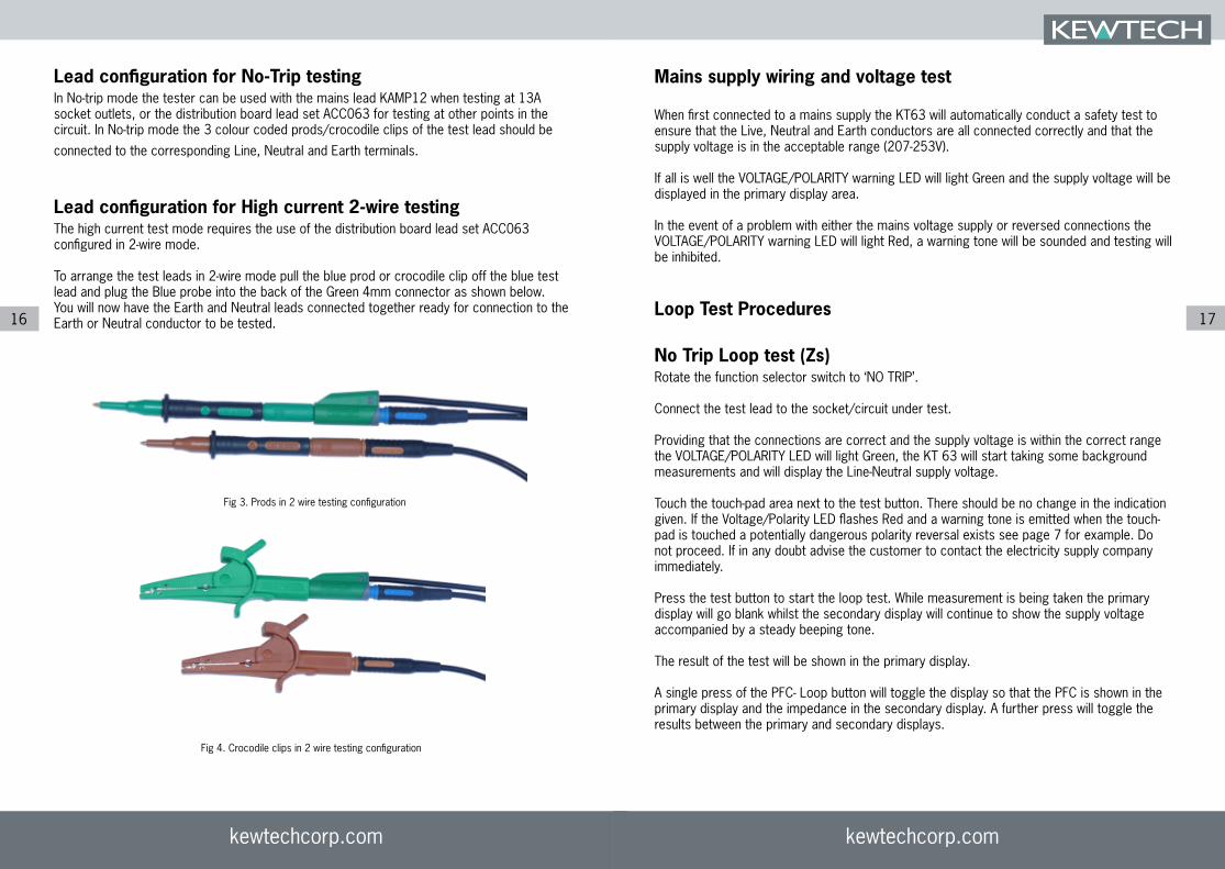
Lead configuration for High current 2-wire testingThe high current test mode requires the use of the distribution board lead set ACC063 configured in 2-wire mode.
To arrange the test leads in 2-wire mode pull the blue prod or crocodile clip off the blue test lead and plug the Blue probe into the back of the Green 4mm connector as shown below. You will now have the Earth and Neutral leads connected together ready for connection to the Earth or Neutral conductor to be tested.
Fig 3. Prods in 2 wire testing configuration
Fig 4. Crocodile clips in 2 wire testing configuration
Mains supply wiring and voltage test
When first connected to a mains supply the KT63 will automatically conduct a safety test to ensure that the Live, Neutral and Earth conductors are all connected correctly and that the supply voltage is in the acceptable range (207-253V).
If all is well the VOLTAGE/POLARITY warning LED will light Green and the supply voltage will be displayed in the primary display area.
In the event of a problem with either the mains voltage supply or reversed connections the VOLTAGE/POLARITY warning LED will light Red, a warning tone will be sounded and testing will be inhibited.
Loop Test Procedures
No Trip Loop test (Zs)Rotate the function selector switch to ‘NO TRIP’.
Connect the test lead to the socket/circuit under test.
Providing that the connections are correct and the supply voltage is within the correct range the VOLTAGE/POLARITY LED will light Green, the KT 63 will start taking some background measurements and will display the Line-Neutral supply voltage.
Touch the touch-pad area next to the test button. There should be no change in the indication given. If the Voltage/Polarity LED flashes Red and a warning tone is emitted when the touch-pad is touched a potentially dangerous polarity reversal exists see page 7 for example. Do not proceed. If in any doubt advise the customer to contact the electricity supply company immediately.
Press the test button to start the loop test. While measurement is being taken the primary display will go blank whilst the secondary display will continue to show the supply voltage accompanied by a steady beeping tone.
The result of the test will be shown in the primary display.
A single press of the PFC- Loop button will toggle the display so that the PFC is shown in the primary display and the impedance in the secondary display. A further press will toggle the results between the primary and secondary displays.
kewtechcorp.com
18
kewtechcorp.com
19
kewtechcorp.com
High current test (Ze)
The high current should only be conducted with the distribution board test lead set ACC063 configured in 2 wire mode. Do not use this function with the KAMP12 mains lead or the distribution lead set in 3-wire configuration.
Rotate the function selector to the HIGH position.
Connect the test lead probes to the circuit under test and press the test button.
The result will be shown in the primary display and the mains voltage will be shown in the secondary display.
Press the PFC-LOOP button to show the PFC/PSC in the primary display and the impedance in the secondary display area.
Note: The reading described here as PFC/PSC will be the prospective fault current for the circuit being immediately tested. This is known as PSC in the case of a test between Live and Neutral or PEFC for a test between Live and Earth conductors.
The 17th edition wiring regulations 2008: amendment 1 2011, call for an IPF value to be recorded, this is
the higher of the PSC and PEFC as described above.
Hands Free Loop testing
The hands free feature can be used in either No Trip or high current test modes.
To enable the hands free feature simply press the HANDS FREE button once, The ‘HANDSFREE’ annunciator will appear flashing on the LCD and will continue to do so until cancelled by a further press of the HANDS FREE button or by changing the function selector switch.
When the HANDSFREE annunciator is flashing all you need to do is connect the test lead to a mains supply and the test will be automatically carried out.
RCD Test Function
Caution
Although fully protected against over voltage to 440V this tester should only be used on a 230V supply
The KT63 will test all of the most commonly encountered RCD’s of both standard (AC) type and selective (ACS) type across the full range of tests required by the 17th Edition of the
wiring regulations.
Test requirements
Each RCD is tested to ensure that:
It operates with a maximum disconnection time of 300ms (AC type) when a fault at its i. rated current is introduced. This is referred to as the x1 test.
It is not prone to ‘nuisance’ tripping and does not trip when a fault of half its rated i. current is introduced. This is referred to as the x½ test
In the case of an RCD rated at 30mA there is an additional requirement that it ii. operates with a maximum disconnection time of 40ms when a fault of five times its rated current is introduced. This is referred to as the x5 test
For the reasons explained below all of the above tests have to be conducted at both 0° and 180° this means that four tests (or for 30mA RCD’s six tests) have to made for each RCD.
The user friendly design of the KT63 simplifies the test process by enabling you to do any of these tests by making just two function selections.
Automatic testFor the most commonly encountered 30mA RCD the test process is even simpler. Just turn the rotary selector to the ‘30mA AUTO’ setting and the KT63 will conduct all six required tests
at the single touch of a button.
Pass or Fail resultIn addition to displaying the time taken for the RCD to trip the KT63 will also indicate whether it has passed or failed the test requirements of the 17th edition.

kewtechcorp.com
20
kewtechcorp.com
21
kewtechcorp.com
Ramp testThe KT63 also includes a diagnostic Ramp test feature. In this mode rather than applying a steady fault current and measuring the time taken for the RCD to trip, the KT63 gradually
increases the fault current and identifies the level of additional leakage at which the RCD trips.This is particularly useful in diagnostic testing of circuits where nuisance tripping is a problem and helps to identify the difference between an over sensitive RCD and excessive leakage from poor insulation or equipment with high leakage.
Sinusoidal polarity (the 0° or 180° test)RCD’s often operate with different reaction times depending upon whether the fault is introduced during the positive or negative half cycle of the AC waveform. Therefore to accurately determine the maximum response time of an RCD it is necessary to test it twice at each given fault current, firstly with the fault introduced during the positive half cycle and
secondly during the negative half cycle.
The KT63 takes care of this for you by alternating the start point of consecutive tests at any given setting. If for example you have selected a test at the rated trip current (x1) of a 100mA RCD, the first press of the test button will apply a 100mA fault current starting on the positive half cycle (0° ) and display the result. A further press of the test button will carry
out another test at the same current but starting on the negative half cycle (180° ).
Test leadsWhere testing is to be conducted at a point on the circuit other than a socket outlet the distribution board test lead set ACC063 is used in 3-wire mode as described in the previous chapter. The probes can be fitted with either prod tips or crocodile clips as required.
Mains supply wiring and voltage testWhen first connected to a mains supply the KT63 will automatically conduct a safety test to ensure that the Live, Neutral / Earth conductors are correctly connected and that the supply voltage is in the acceptable range of 207-253V.
If all is well the VOLTAGE/POLARITY warning LED will light Green and the supply voltage will be displayed in the primary display area.
In the event of a problem with either the mains voltage supply or reversed connections the VOLTAGE/POLARITY warning LED will light Red, a warning tone will be sounded and testing will be inhibited.
RCD test procedure
Select the type and rating of the RCD to be tested with the rotary function selector switch.
Connect the 4mm plugs of the chosen test lead to the corresponding L, N & E terminals of
the KT63 and connect the other end to the socket or circuit terminals under test.
If using the distribution board test lead set ACC063 observe the correct polarity by connecting the Brown probe to the Live conductor, Blue to Neutral and Green to Earth.
Touch the touch-pad area next to the test button. There should be no change in the indication given. If the Voltage/Polarity LED flashes Red and a warning tone is emitted when the touch-pad is touched a potentially dangerous polarity reversal exists see page 7 for example. Do not proceed. If in any doubt advise the customer to contact the electricity supply company immediately.
User selected testThe recommended order of tests is firstly at ½x the rated current followed by a test at the
rated current and finally, for 30mA RCD’s only, 5x the rated current.
The default test parameters of x½ for the current multiplier and 0° for the phase polarity will be automatically selected for the first test. These will be displayed on the LCD along with the Line-Neutral voltage.
Press the test button and a test will be conducted at these settings. If successful and the RCD has failed to trip a single beep will sound and the main display will be similar to figure 5.
Displaying result of 1st ½x test (Figure.5)
Changed polarity ready for 2nd test
(Figure 6)
kewtechcorp.com
22
kewtechcorp.com
23
kewtechcorp.com
The main display shows that the fault current was applied for over 2000 milliseconds (2 seconds) without tripping the RCD. The secondary display confirms that this passes the
requirements of the 17th edition.
In the event of the RCD failing the test and tripping within 2 seconds at half the rated current the main display will show the trip time and the secondary display will show ‘FAIL’. A short 2 tone alert will also sound.
After displaying the result for a few seconds the tester will switch to the 180° phase polarity setting in readiness for the next test. (Figure 6)
When both tests have been conducted at the x½ setting press the multiplier button to change the test current to the x1 setting.
Press the test button to conduct a test at the x1 setting at 0°. The result will be shown as a pass if RCD trips within 300ms. After displaying the result for a few seconds the tester will switch to the 180° phase polarity setting in readiness for the second test at the x1 current
setting.
If the 30mA setting has been selected a x5 current option will be available by using the multiplier button. This option is not available, or required, for other ratings.
30mA Automatic testThe Auto test function will set up the tester to automatically conduct all 6 tests by a single
press of the test button. All you have to do is reset the RCD after it trips.
Upon completion of the auto test routine the results for each setting can be recalled by using the RCD-RECALL button to cycle through the routine.
Ramp testUse the rotary switch to select the rating of the RCD.
Press the multiplier button until the symbol is displayed.
Press the test button to start the test. The fault current applied will increment in 3mA steps until the RCD trips.
If nuisance tripping on a circuit is a problem this function can be used to retest the RCD with other appliances systematically connected and removed.For example a 30mA RCD may trip at 12mA on ramp test with an appliance connected and then at 27mA with the appliance removed. You will know that the appliance is leaking approximately 15mA.
Specifications and tolerances
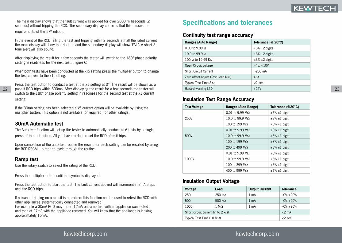
Continuity test range accuracyRanges (Auto Range) Tolerance (@ 20°C)
0.00 to 9.99 Ω ±3% ±2 digits
10.0 to 99.9 Ω ±3% ±2 digits
100 Ω to 19.99 KΩ ±3% ±2 digits
Open Circuit Voltage >4V, <10V
Short Circuit Current >200 mA
Zero offset Adjust (Test Lead Null) 4 Ω
Typical Test Time(2 Ω) <2 sec
Hazard warning LED >25V
Insulation Test Range AccuracyTest Voltage Ranges (Auto Range) Tolerance (@20°C)
0.01 to 9.99 MΩ ±3% ±1 digit
250V 10.0 to 99.9 MΩ ±3% ±1 digit
100 to 199 MΩ ±6% ±1 digit
0.01 to 9.99 MΩ ±3% ±1 digit
500V 10.0 to 99.9 MΩ ±3% ±1 digit
100 to 199 MΩ ±3% ±1 digit
200 to 499 MΩ ±6% ±1 digit
0.01 to 9.99 MΩ ±3% ±1 digit
1000V 10.0 to 99.9 MΩ ±3% ±1 digit
100 to 399 MΩ ±3% ±1 digit
400 to 999 MΩ ±6% ±1 digit
Insulation Output VoltageVoltage Load Output Current Tolerance
250 250 kΩ 1 mA –0% +20%
500 500 kΩ 1 mA –0% +20%
1000 1 MΩ 1 mA –0% +20%
Short circuit current (in to 2 kΩ) <2 mA
Typical Test Time (10 MΩ) <2 sec

kewtechcorp.com
24
RCD Test range accuracy
Supply voltage 195V – 253V AC 50Hz
Test current accuracy (½ I) –0% to –10%
Test current accuracy (I, 5I) +0% to +10%
Trip time accuracy up to 1 second ±(1% + 1ms)
Trip time accuracy over 1 second ±(1% +10ms)
For repair and calibration please return to us at :
Express Cal, Unit 2, Shaw Wood Business Park, Shaw Wood Way, Doncaster DN2 5TB
Kewtech Corporation Limited Midas House
Unit 2b, Stones Courtyard,High Street, Chesham, Bucks HP5 1DE
T: 01494 792 212F: 01494 791 826
Loop Test Range Accuracy
Range Accuracy
No trip 0.00 – 9.99 Ω ± 5% ± 5 digits
No trip 10.00 – 99.9 Ω ± 3% ± 3 digits
No trip 100 - 500 Ω ± 3% ± 3digits
High Current 0.00 - 500 Ω ± 3% ± 3 digit