Embed Size (px)
Citation preview

STEREO SPACE, SHADING AND SHADOWING
K.S. Andonian* and S. Toidat *School of Architecture, Carleton University, Ottawa, Ontario tSystems Design Department, University of Waterloo. Waterloo. Ontario
Ahstract
219
Hidden-surfaces prohlem, shading and shadowing for monocular and hinocular scenes have hecome significantly simplified in stereo space. Planar surfaced objects arc approximated hy polygonal surl:lces, and ranking the surface-planes with rcspect to given eycpoints and light sources is dctermined hy stereo dcpth measurcmcnt calculations.
The transformation of thc cycpoint and light source to infinity in stereo spacc simplifies thc calculation of the angles betwecn a normal to the surface and the vectors to the light source and thc viewer, for light sourcc beams and eye-to-object connecting lines are always perpendicular to each other. The calculation of the distance from the surface to the light source and the orientation of the surface become trivial. Furthermorc, a parallel projection from the light source illuminates the highest ranked planes and shadows the rcst, whereas a parallel projection from the eyepoint eliminates the hidden surfaces.
REPRESENTATION TRIDIMENSIONNELLE, OMBRE ET PENOMBRE
Resume
Le prohlcllle des surfaces cachees, ainsi <.Jue les tlllestions d'omhre et de pcnomhre pour des scenes Illonoculaires et hinoculaires Ollt ete grandement simplifies en representation tridilllensionnelle . On ohtient des approximations des objets il surfaces plal\es par des surfaces polygonales, et la mise en ordre des plans des surfaces par rapport il des points d 'ohservation et <\ des sources lumineuses donncs est determinee par des calculs utilisant des mesures de profonde llr.
Le transfert du point d'ohscrvation ct de la source lumineuse it I'infini cn representation tridimensionnclle simplilie le calcul dcs angles entre une normale a la surf~lCe et Ics vecteurs diriges vers la source lumincuse et I 'observateur, puisque les faisceaux de la source lumincuse et les droites joignant le point d 'observation a I 'o bjet sont toujours il angle droit. Les calculs de la distance de la surface a la so urce lumineuse et de I 'orientation de la surface deviennent Cicmentaires. De plus, une projection paral\c\c provenant de la source de lumicre illumine les plans de rang le plus eleve et olllhrage les autres, tandis qu'unc projcction parallcle provenant du point d 'observa tion elillline \cs surfaces cachees.


221
STEREO SPACE, SHADING AND SHADOWING
K.S. ANDONIAN, S. TOIDA
SCHOOL OF ARCHITECTURE, SYSTEMS DESIGN DEPT.
CARLETON UNIVERSITY, UNIVERSITY OF WATERLOO
OTTAWA, ONTARIO WATERLOO, ONTARIO
I. Introduction
In a perspective display of a 3-D scene, elimination of hiddenlines or hidden-surfaces, accurate shading and shadowing convey monocular depth information. However, the perception of depth of a point in the same 3-D scene involves only binocular depth cues - binocular disparity, convergence of eyes, focusing. Since a point can not carry monocular depth cues, that is, its depth position is imperceptible if viewed monocularly, the disparity between the left and right eye images is responsible for the perception of its third dimension.
Because binocular disparity is such a powerful depth cue, it is possible to produce an artificial impression of depth by giving each eye a slightly different picture with patterns even devoid of all monocular depth cues and by making the eyes converge as they would if they were looking at the real 3-D object. [1]
The reference material contains many studies of computer representation of 3-D objects with hidden-surfaces eliminated - some include also shading, and very few refer to shadowing - and, significantly, [8] almost all of them apply to monocular perspective image generation. [6] The disadvantage of stereo technique, according to Newman and Sproull [2], has been the generation of two "completely independent" pictures.
The question of how independent the generated stereoscopic images really are is an interesting one, and whether the stereo depth information can be used in solving hidden-line problem, shading or shadow ing for computer generated scenes is the problem being investigated here.
222
11. Transformation into new space
Let (x, y, z) be a point in a 3-D space called V and let (xl' Yl-2' x2) be a point in another 3-D space called VI.
where
Let AT be a transformation from V to VI defined as AT ((x, y, z)) = (xl' Yl-2' x2)
Xl Ox + dO - dz =
1 z
I = ~ ( 1 ) Yl-2 Z
Xl Ox - dO + dz = 2 z
where d and 0 are constants. The AT transformation is obviously a projective transforma
tion. Hence it has all the properties of a projective transformation. In addition to those properties we shall show that AT gives stereoscopic images of an object in V.
Theorem 1: Let (-d, 0, 0) and (d, 0, 0) be the positions of left eye and right eye of a viewer in V, respectively. Let z = 0 be the position of picture plane in V. Then (xl' y,2 2 and (x2 ' y122 are the left eye and the right eye images of a point (x, y, z) in V, respectively.
Proof: In Fig. 1. Xl and yl are coordinates on picture plane. x, y, z are coordinates of the space V. P is a point in space v. (xl' Yl) is the left eye image of P and (x2 ' Y2) is the right eye image of P on the picture plane. By simple geometrical examination of Fig. 1. the following relationships can be obtained:
x + d z 'L = Xl + d 0- Y1 1
x - d z y 7-:([ - 0- Y2 2
From (2) we can obtain:
Xl = !Llx + d) 1 z
y, _Q.l
= Y2 z
Xl 0 (x - d) = 2 z
- d
+ d =
(2)
Ox + dO - dz z
Ox - dO + dz z
(3)
(3) clearly is identical to (1). Hence the theorem is true . Discussion: As we see in theorem 1, left eye and right eye images are not completely independent. As a matter of fact they share one coordinate among them. Hence to generate the two images we do not have t? generate four different coordinate informations. Furthermore, there 1S

223
very little difference between xl and Xz as seen in (3). All the in
formation that are necessary to calculate Xz are in xl with difference
only in signs i.e. Ox, dD, dz and z. Hence calculation for xl and Xz takes less than twice as much time as that for xl (or xZ).
Calculation of xl and y'l-2 is computationally equivalent to
that of monocular perspective picture. Hence we can obtain stereoscopic images with little extra effort from monocular perspective images.
Another interesting property of AT transformation is that the eye points are transformed into infinity by AT. Hence in V' space light-beams become parallel to coordinate axes. That is,
i f 1 eft eye is at ( - d, 0, 0) in V,
then X' = -d 1
Xz -+ -co in V', and
if right eye is at (d, 0,0) in V,
then x' -+ +co 1
x' = d in V'. 2
Hence in V' lightbeams coming into left eye are parallel to Xz axis,
and lightbeams coming into right eye are parallel to xl axis. Thus ,
(xl' Yl-2)' the projection of transformed object onto the xl Yl-2
plane, is a perspective picture from left eye, and (xZ' Yl-2) is that
from ri ght eye. (Refer to Fi g. 2.)
Theorem 2: xl gives the depth information for (xZ' Yl-2) picture, and
Xz gives the depth information for (xl' Yl-2) picture.
Proof: Since lightbeams are parallel to the Xz axis for (xl' Yl-2) pictures, points on the same lighbeam have the same xl value. But from ( 1 )
X I - X I 2 1
o = 2d (1 - - ) z . (4)
Hence if xl is the same for two points in V', then Xz is a function of
z only, and z is the depth information in V. Hence by looking at Xz we can tell which point is in front of the other for (xl' Yl-2) pic
ture. Thus, Xz gives the depth information for (xl' Yl-2) picture.
Similar for (xZ' Yl-2) picture. Other properties of AT
AT is a projective transformation, hence it transforms lines into lines, planes into planes, conic section into conic section, pencil of lines into pencil of lines, et cetera. For those properties see, for example, [3],

224
Boundaries of stereo space and stereo depth calculation
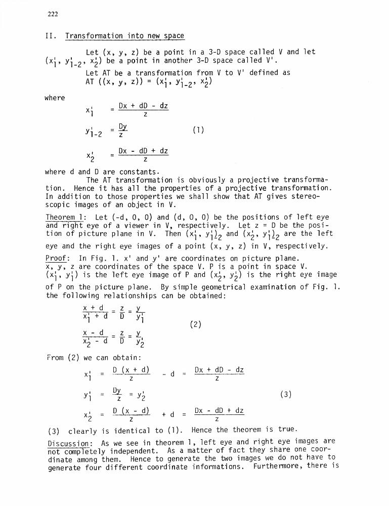
With equation (4) it ;s possible to define the boundaries of transformed stereo space and calculate the relative position of a point P(x,y,z) in V' space. (Refer to Fig. 3.) Since the eye-points are at infinity in V', the relative position of points, lines, planes and objects must be checked with respect to the picture plane. From (4) we can conclude that: (a) If Z = 0 X' - x' = 0 then x' = x'
2 1 2 1 In this case P(x,y,z) is on the picture plane and both images - right and left eye - are identical. Thus, the location of the picture plane is defined in V' as perpendicular to xl x2 plane, dividing the xl and
x2 axes by 45° angle and coinciding with Yl-2 axis.
(b) If z > 0 x' 2 - x' 1 > 0 then x' > x' 2 1
In this case P (x ,y ,z) is behind the picture plane.
( c) If z < 0 X I - X I 2 1 <
In this case p(x,y,z) is in
(d) If z = +00 X' 2 - x' 1
Thus, all vanishing points allel to picture plane and respectively.
0 then x2 < x' 1
front of picture plane.
= 2d then x' = 2 2d + xl'
in stereo space define a plane which is parcrosses the xl and x2 axes at -2d and 2d,
The stereo perspective depth calculation is applied to find out the relative position of a point P with respect to a plane PLo The calculation is as follows (Refer to Fig. 4.):
Given: the plane equation of PL
Ax ' 1 + BYl-2 + ex I
2 + 0 0
PL PL PL
and the point coo rd in a tes P(x ' I x2) . 1 ' Yl-2' P P P
Since parallel projection of P produces perspective images on plane PL at PRE and PLE, the only unknowns for PRE and PLE coordinates are ~ ~
and ~~
Substituting x2 for x' 2 and Yl-2 for y 1-2' then xl for xl and P PL P PL P PL
Yl-2 forYl_2 into (5) we solve for x' 1 and x2 ' respectively.
P PL RE LE

Ill. Hidden-line/surface problem applied to stereoscopic images
With stereo application, some of the monocular depth cues -elimination of hidden lines, exaggerated perspective and intensity
225
cues - become unnecessary in the case of wire-frame representation of objects. The artificial visual impression will be the perception of transparent objects in 3-D. However, to have the sensation of "opaque" objects, hidden-line problem (HLP) must be applied to stereoscopic images.
Binocular HLP: Almost all of the existing monocular HLP solutions applied to stereoscopic images in the stereo space, V', will require less than twice as much time as that of monocular image. For, AT transforms objects from E e Coordinate S stem (ECS) into Stereo Perspective Coordinate System SPCS and the following technlques, (a) and (b), can be applied [6] in it:
Technique (a): The same plane equation and line equation can be used in SPCS to find out which parts of the tested line, if any, is hidden for both right and left eye images.
Technique (b): Since SPCS generates perspective images by parallel projection, the same stereo screen window can be checked by stereo depth calculation if any object is visible within it.
In applying Warnock's algorithm to stereo space~ two perpendicular window boxes - are for each eye image - sharing the same stereo screen area can be checked by stereo depth calculation to find out if parts of objects are seen within them. (Refer to Fig. 5)
In the case of scan-line algorithm, the same horizontal linewindow of the stereo screen can be checked for parallel projections to find out relative positions of lines with respect to left and right eyepoints. (Refer to Fig. 6)
IV. Shading and shadowing in stereo space
After hidden-surfaces eliminated, shading must be applied to visible planes to make the object appear "textured" in a 3-D scene.
The light source can be assumed to be at any position. If it is not located at the same point as the eye, shadowing must be added to the 3-D scene.
The simplified brightness calculation of a surface as seen by the eye includes the distance from the surface to the light source, r, the angle between a normal to the surface and a vector to the light source, 8i, and the angle between the surface normal and a vector to the v i ewe r, 8v.
Since shading and shadowing involve perspective projections of surfaces from the eyepoint and light source, they become simply a stereo problem. The transformation of the eyepoint and light source to infinity in stereo space simplifies the calculation of intensity (8i, Sv) for shading, for light source beams and eye-ta-object connecting lines are always perpendicular to each other. The calculation of r and the orientation of the surface become trivial since stereo depth

informs the relative position of the surface in stereo space. more, a parallel projection from light source illuminates the surfaces with shades and shadows the rest, whereas a parallel tion from eyepoint eliminates the hidden surfaces .
Furthervisible projec-
With scan-line shading and shadowing application to stereo space, more accurate brightness of surfaces can be achieved since the relative position of lines or points comprising the lines are easily calculated by stereo depth.
In the case of multiple light source illumination, every single light source and the eyepoint can be considered as a stereo problem. Thus, shading and shadowing must be calculated in the transformed stereo space accumilatively. The resultant monocular perspective image at the end represents a 3-D scene where elimination of hidden-surfaces, shading and shadowing are applied to it.
For binocular scenes the shadow contours are the same as they are for monocular scenes. Since the distance between right and left eyes is very small, the brightness differences between monocular and binocular images can be ignored. This helps to perceive stable stereo scenes devoid of shining.
v. Ranking of planes in stereo space and its applications
Ranking of surface-planes in stereo space with respect to given eye-points is determined by the test of each ordered plane against the others. Applying the sign-test position evaluation technique [4] to all planes, we may determine the rank of each plane. Thus, if some part of an ordered plane is behind another plane, the former is classified one rank lower than the latter. If parts of an ordered plane are behind N number of planes, the ordered plane is classified as (N + l)-th rank. The highest rank planes are ones which carry number 1 classification and are not hidden by any other plane.
The sign-test position evaluation technique also determines the mode of each plane relationship - convex or concave - with respect to other planes. (Refer to Fig. 7)
If the mode of all the surface-plane relationships of an object is convex, then the object is a convex polyhedron. In this case binary ranking is applied to them. The highest ranked surface-planes are vis ible from the eye-point and the rest hidden, whereas the highest ranked surface-planes are illuminated from the light source and the rest shaded. There is no shadowing problem.
If at least one mode out of all surface-plane relationships of an object is concave, then the object is a concave polyhedron. In this case the object is specified as a number of convex polyhedra [7] for binary ranking. Thus, only the resultant highest ranked su rfaceplanes are reranked with respect to eye-point and light source for shadowing, for the rest is all hidden/shaded.
Shadowing is a similar process of hidden-surface elimination but from the light source. In both processes higher ranked planes are parallelly projected onto lower ones in stereo space to determine visible/hidden or illuminated/shadowed portions, if any.

227
VI. Conclusion
To produce an artificial impression of depth by stereo vision two stereoscopic images are generated - one appropriate to each eyeand presented to the two eyes separately. The disadvantage, however, has been the assumption of stereoscopic images being two completely independent pi ctures. [2]
A transformation, AT, has been shown sufficient to produce two stereoscopic images. Thus, obtaining binocular pictures does not require twice as much time as that of monocular picture.
AT transforms non-parallel lightbeams in V space into parallel lightbeams in stereo space. Hence it simplifies hidden line elimination, shading and shadowing for monocular and binocular 3-D scenes.
References
[1J Julesz, B. Foundations of Cyclopean Perception The University of Chigago Press, Chigago, (1971).
[2] Newma~, W.M. and Sproull, R.F . Principles of Interactive Computer Graphics. McGraw-Hill, in Computer Science Series, New York, (1973),240-24l.
[3] Gans, D. Transformations and Geometries . Appleton-Century-Croffs, in Mathematics Series, New York, (1969), 165-188.
[4] Andonian, K.S. Hidden-Line Elimination for Convex Polyhedra. M.A.Sc. Thesis, University of Waterloo, Ontario, (1973), Chapter I I 1.
[ 5 ] L 0 u t re 1, P. A sol uti on to the IIHi dden-Li ne ll Problem for Computer-Drawn Po lyhedra . New York Univers i ty, New York, (1967),8-22.
[6] Sutherland, I . E., Sproull , R.F., Schumaker, R.A. A Characterization of Ten Hidden-Surface Algorithms. Computi ng Surveys, Vo 1 6. , No . 1. , (March, 1974).
[7] Roberts, L.G. Machine Perception of 3-D Solids . Technical Report, No. 315, M.I.T., Lexington, Mass., (May 1963).
[8] Bouknight, J. and Kelley, K. An Algorithm for producing half-tone computer graphics presentations with shadows and movable light sources. University of Illinois, Urbana , Illinois, SJCC, (1970).

228
Figure - 1
Stereoscopic images of a point (x,y,z ) on the picture plane p-p in V space.
Fi gure - 2
The eyepoints are transformed to infinity in V' space.
Fi gure - 3
Boundaries of transformed stereo space are defined by planes aehd, efgh, fbcg, bijc and ijda. Points abed define the picture plane in V'. Plane efgh defines the vanishing points in V'.
P(x ,y,z )
y
___ _____ ---=too RE
4 a "":::;:==---+-~+E:~--+----'=~ b ~

Fi gure - 4
Perspective images of point P(x1, Yl-2' x2) on plane PL
are PRE (x2, Yl-2) and PLE
(xl' Yl-2) viewed from right and left eyepoints in stereo space.
LE
Fi gu re - 6
)(
I
wls ~r
The same horizontal linewindow checked for parallel projections in stereo space.
PL
Figure - 5
Two perpendicular window boxes, a and b, share the same screen area, c, in stereo space.
EP •
(A ) I
I
229
I E P " . I "
,,·'EP
EP •
I I
I
I
I I
I
EP •
I I
Fi gure - 7
cv Q.."
I I
EP •
(B)
Two different relationships in a three-plane pattern: (A) convex relationship (8) concave relationship.