Embed Size (px)
DESCRIPTION
A detailed tutorial in making a differential drive
Citation preview

www.robotix.in

Components of a Differential Drive
Power
SystemControl
BoxDrive
Mechanism
www.robotix.in

Power System
Power
Supply
(220v AC)
Transformer
Rectifier
Circuit
DC Out
www.robotix.in
Materials Required
www.robotix.in
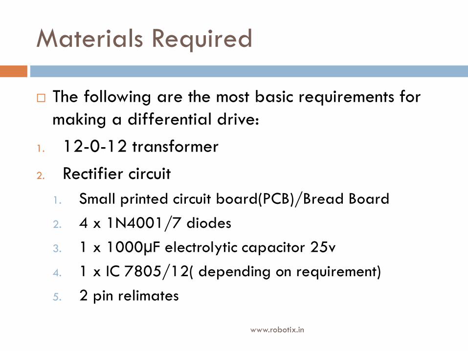
The following are the most basic requirements for
making a differential drive:
1. 12-0-12 transformer
2. Rectifier circuit
1. Small printed circuit board(PCB)/Bread Board
2. 4 x 1N4001/7 diodes
3. 1 x 1000µF electrolytic capacitor 25v
4. 1 x IC 7805/12( depending on requirement)
5. 2 pin relimates

Materials required (contd.)
www.robotix.in
3. Soldering Iron and wire( if using PCB)
4. DC motors
5. Switches
6. Multi /single strand wire
7. Multi-meter

Transformer( Recap)
A transformer is a device that transfers electrical
energy from one circuit to another through inductively
coupled conductors.
To make a simple differential drive, a simple
transformer with following specifications can be used:
1 Amp, C.T. ‐12 V.( it steps down a 220V AC to 12 V
AC.
www.robotix.in

Centre Tap Transformer
220 V AC
supply
12V
AC
-12V
AC
www.robotix.in

Rectifier Circuit
www.robotix.in
PCB
Line matrix PCB Dot matrix PCB

Rectifier Circuit
The top and bottom sections of the
bread board contains slots that are
horizontally shorted, while the
middle section contains slots that are
vertically shorted. www.robotix.in
Bread Board

Rectifier Circuit-Diodes
www.robotix.in
Diodes
The usually used rectifier diodes re the 1N4001
and the 1N4007. The only difference between them
is that they have different voltage and current
ratings.

Rectifier Circuit-Capacitor
www.robotix.in
Electrolytic Capacitor
Most electrolytic capacitors are polarized, i.e., they
have a positive and negative terminal. Connecting
them to wrong terminals of power supply can destroy
it. Adding to this, these capacitors are used only for
DC voltages.
Fig: A blown capacitor

Rectifier Circuit-Voltage Regulator
www.robotix.in
These ICs are voltage regulator integrated circuits.
The voltage regulator IC maintains the output
voltage at a constant value. The xx in 78xx
indicates the fixed output voltage it is designed to
provide. 7805 provides +5V regulated power
supply. Similarly there are several other ICs
available in this category like 7806, 7809, 7812,
7815.

www.robotix.in
Rectifier Circuit-Voltage Regulator
Another fact to note about this series of ICs is that
they have a voltage range in which they work. For
any voltage above that range the IC goes into a
thermal shutdown and will give you a very low
arbitrary voltage value. For example, the 7805 IC
has a range between 5V and 16V.
2 31
www.robotix.in
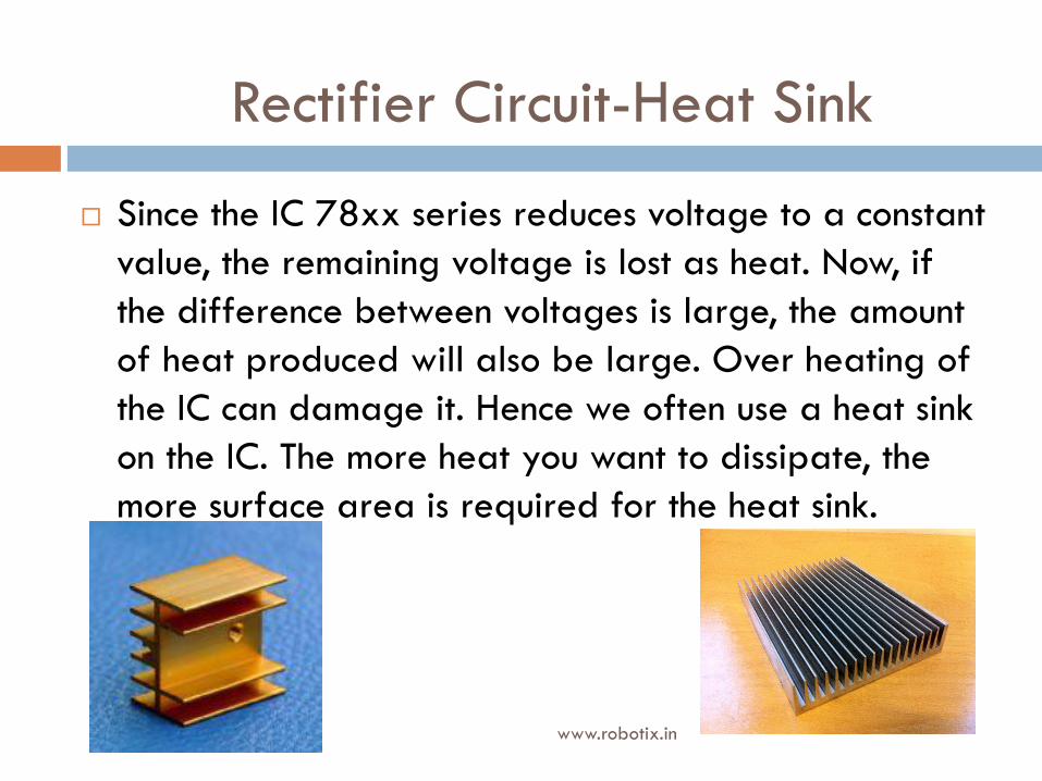
Since the IC 78xx series reduces voltage to a constant
value, the remaining voltage is lost as heat. Now, if
the difference between voltages is large, the amount
of heat produced will also be large. Over heating of
the IC can damage it. Hence we often use a heat sink
on the IC. The more heat you want to dissipate, the
more surface area is required for the heat sink.
Rectifier Circuit-Heat Sink

Rectifier Circuit-Relimates
www.robotix.in
A relimate is just a connector that can be soldered onto a PCB. It has a female and a male part. There are different kinds of relimates, 2 pin , 3 pin, 4 pin and so on to several pins.
Another point to add is that it is always good to follow the convention that the
black wire is connected to the
ground. This helps in debugging
faults at the end without much
difficulty.
Female
part
Male
part

Rectifier Circuit-Soldering
www.robotix.in
A soldering iron is used for melting the solder wire
onto the components. The solder wire is essentially
made up of solder and often it comes with a flux
coating. A flux is used to ensure that the solder does
not stick on the solder iron. The molten solder sticks to
the copper of the PCB when it comes in contact with it.
The practical aspects of soldering will be dealt with in
the hands-on classes of KRAIG.

DC Motors
www.robotix.in
DC motors come in different voltage ratings and
rpms. They have to be selected based on the
application. Where speed is necessary, we obviously
need to go for the higher rpm motors. Where torque
is more important, we need to go for low rpm geared
motors. For the purpose of simple DD making we
usually use either the 150 rpm 5V motor or the
100/60 rpm 12V motor. 5V motor
12V motor

Switches
www.robotix.in
For the purpose of controlling a differential drive,
the best kind of switch is the three way switch. It has
a central off position with two extreme positions for
two different polarities. Such switches are called
DPDT(Double pole double throw) Centre Off
switches.

www.robotix.in
DC power
To motor
Switches

Wires
www.robotix.in
There are two kinds of wires available. One is the
multi strand wire in which there are several strands
of copper wire within the plastic insulation. For using
wires to interconnect slots on the bread board, we
have to use the single strand wire. Whereas for
interconnecting wire, multi strand is the best as the
single strand wire may break on twisting.

Multi-meter
www.robotix.in
A multi meter is a device used to measure
parameters like voltage( AC/DC), resistance,
capacitance, test short etc. It is a very handy device
when debugging circuits or trying to understand
how a circuit works.
www.robotix.in
Rectifier Circuit
Rectifier Circuit
www.robotix.in
Let us first see how we can set up a rectifier circuit
on a bread board.(Remember though that this is not
the only way that it can be done).
http://www.youtube.com/watch?v=JEWKufHjAUU&
feature=plcp

www.robotix.in
Rectifier Circuit

Drive Mechanism
www.robotix.in
Now that we are done with the power system and
the control box we only have the chassis remaining
to assemble.
The chassis can be just about anything. For example
it could even be just a piece of cardboard with
motors attached to it. But then when we take into
consideration the strength of the chassis the best
material is wood or Perspex.
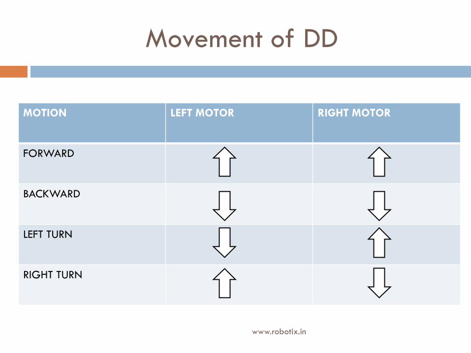
Movement of DD
www.robotix.in
MOTION LEFT MOTOR RIGHT MOTOR
FORWARD
BACKWARD
LEFT TURN
RIGHT TURN

Differential Drive Chassis
www.robotix.in

Shop Location
www.robotix.in
Electronics:
Choudhary Electronics(in Tech Market)
Carpentry:
Tech market
Outside Puri Gate
Prem Bazaar
Umesh Carpenter
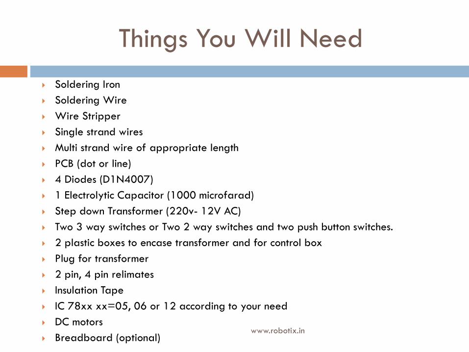
Things You Will Need
www.robotix.in
Soldering Iron
Soldering Wire
Wire Stripper
Single strand wires
Multi strand wire of appropriate length
PCB (dot or line)
4 Diodes (D1N4007)
1 Electrolytic Capacitor (1000 microfarad)
Step down Transformer (220v- 12V AC)
Two 3 way switches or Two 2 way switches and two push button switches.
2 plastic boxes to encase transformer and for control box
Plug for transformer
2 pin, 4 pin relimates
Insulation Tape
IC 78xx xx=05, 06 or 12 according to your need
DC motors
Breadboard (optional)

Things you will need
www.robotix.in
Link to Required materials: http://goo.gl/S8YDr


![PIANO CONCERTO IN F 2nd Movement for Clarinets · 102 102 102 102 102 102 102 102 102 102 102 10 44 [Title]](https://img.dokumen.tips/doc/110x75/5e3946b540eed0696e2e90d2/piano-concerto-in-f-2nd-movement-for-clarinets-102-102-102-102-102-102-102-102-102.jpg)