Embed Size (px)
DESCRIPTION
Â
Citation preview
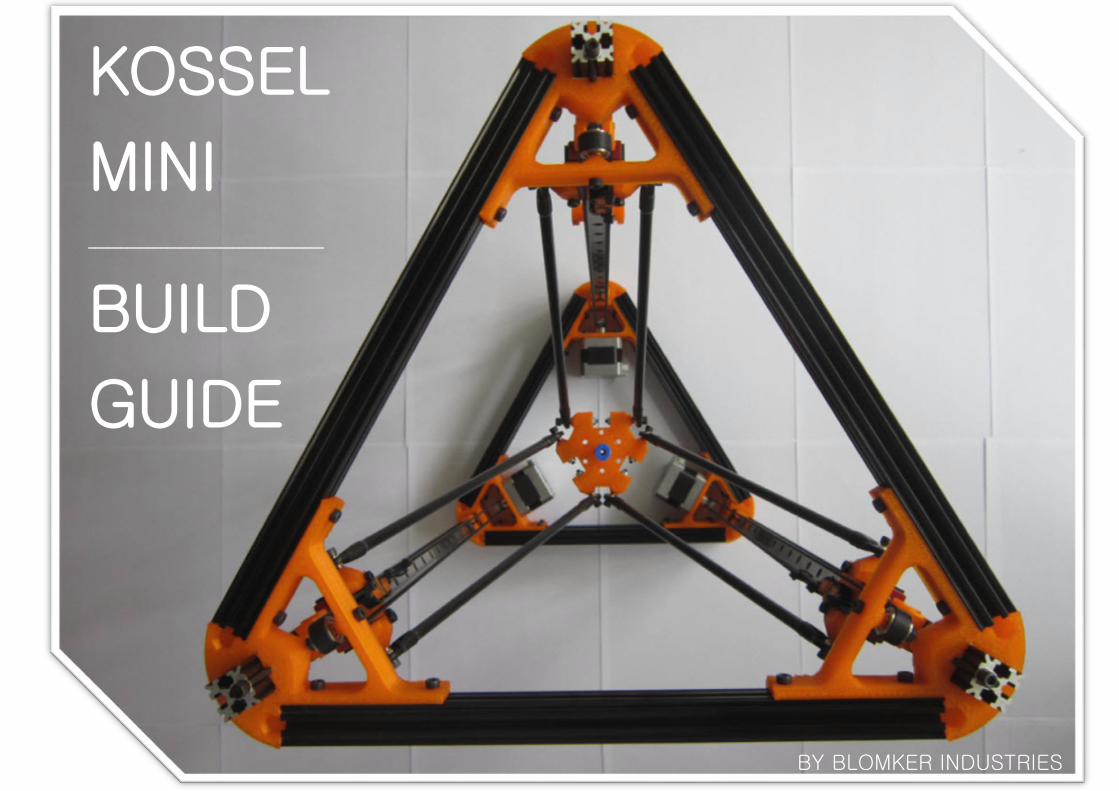
KOSSEL
MINI ____________________________________
BUILD
GUIDE
BY BLOMKER INDUSTRIES
a minimalist yet revolutionary delta robot 3d printer designed by Johann Rocholl [reprap.org/wiki/Kossel]
aim to provide easy to follow step-by-step instructions on assembly and
calibration of Kossel Mini kit supplied by Blomker Industries [blomker.com]
#Kossel Mini
#This Build Guide
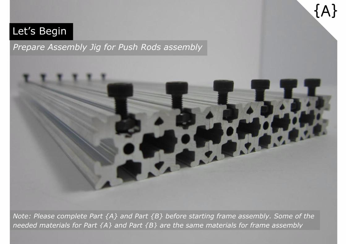
Let’s Begin
Prepare Assembly Jig for Push Rods assembly
Note: Please complete Part {A} and Part {B} before starting frame assembly. Some of the
needed materials for Part {A} and Part {B} are the same materials for frame assembly
{A}

M3 Nut = 2 pcs
M3 x 8mm Cap Screw = 2 pcs
OpenBeam 240mm = 1 pc
pc
{A01}
[Prepare Parts]
Parts required for Push Rod Assembly Jig as shown above

M3 x 8mm = 2 pc
{A02} [Tools]
M3 Allen Key
Insert M3 Nut into OpenBeam slot guide and fasten it with M3x8mm
Cap Screw. Repeat the same at the other end of OpenBeam.
[Assemble]
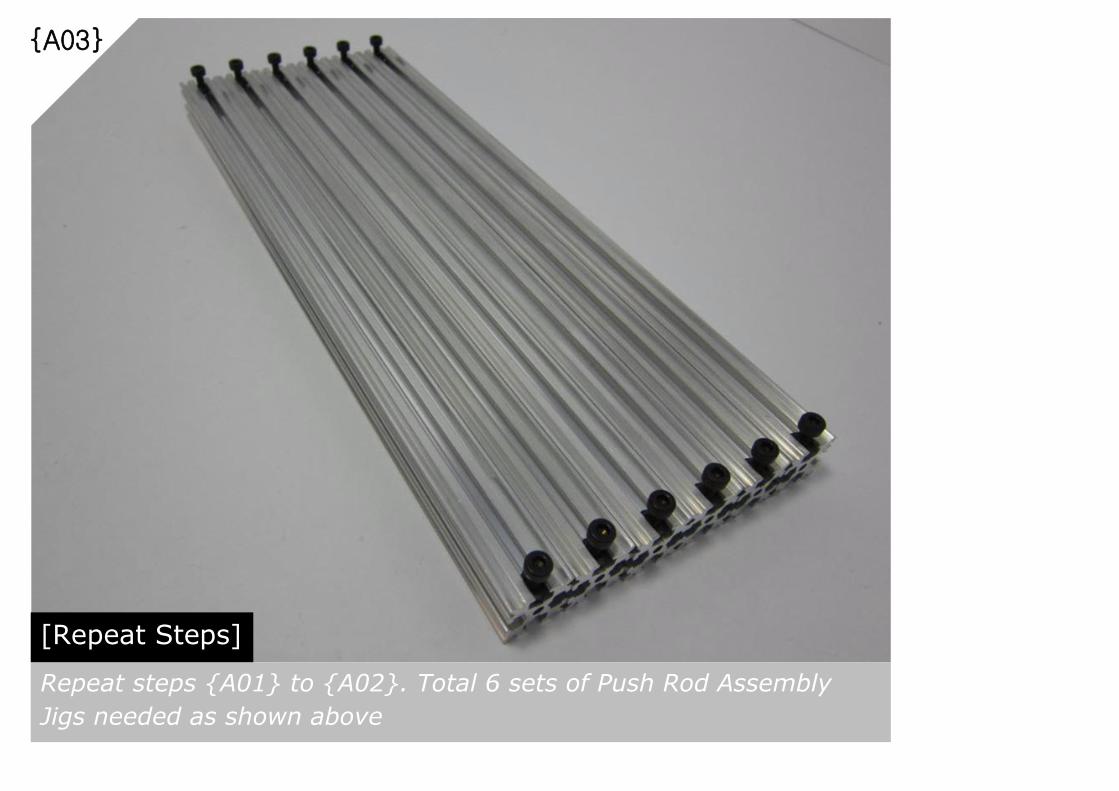
{A03}
[Repeat Steps]
Repeat steps {A01} to {A02}. Total 6 sets of Push Rod Assembly
Jigs needed as shown above

Let’s Push Forward
Assemble the Push Rods
Note: Push Rods assembly quality has direct impact on the final build quality of Kossel Mini.
Advisable to go thru and understands all the steps in Part {B} before proceed further
{B}

[Prepare Parts]
Parts required for Push Rod Rod End assembly
{B01}
M4 x 20mm Set Screw = 1pc
Traxxas Rod End = 1pc
Traxxas Ball Joint = 1pc
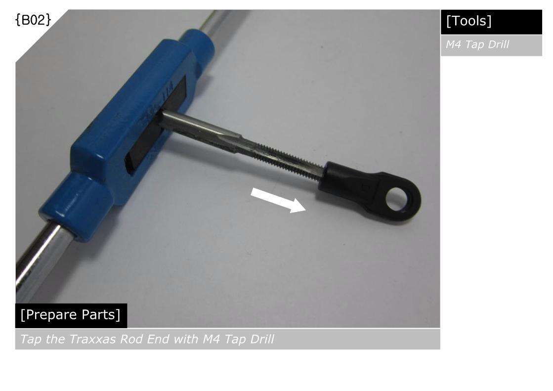
{B02}
[Prepare Parts]
Tap the Traxxas Rod End with M4 Tap Drill
[Tools]
M4 Tap Drill
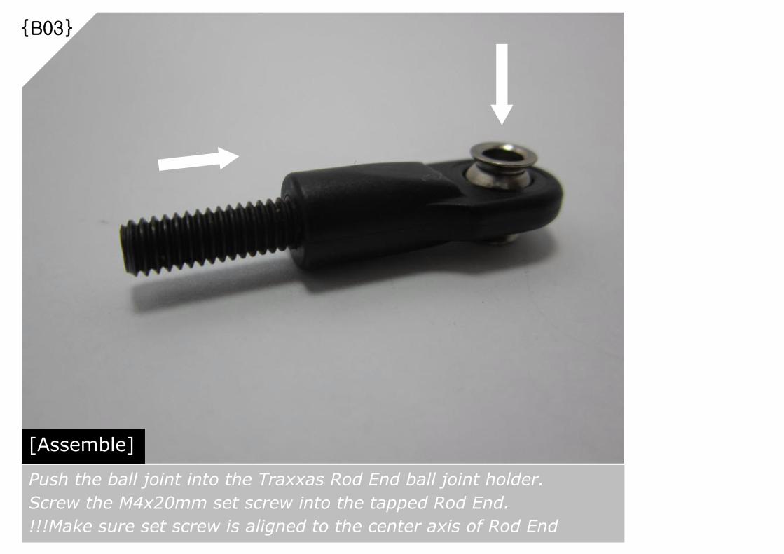
{B03}
[Assemble]
Push the ball joint into the Traxxas Rod End ball joint holder.
Screw the M4x20mm set screw into the tapped Rod End.
!!!Make sure set screw is aligned to the center axis of Rod End

{B04}
[Repeat Steps]
Repeat steps {B01} to {B03}. Total 12 sets of Push Rod Rod Ends
assembly needed as shown above

{B05}
[Prepare Parts]
Parts required for Push Rods full assembly
180mm Carbon Fiber Rod = 6 pcs
Assembled Rod End = 12 sets

[Prepare Parts]
Apply slow-setting epoxy glue on the set screw of Rod End
{B06} [Item]
Slow-Setting
Epoxy Glue

{B07}
[Assemble]
Slowly join the Carbon Fiber Rod and Rod End. Excess epoxy will be
dissipated at the wet joint area. Swiftly repeat steps {B06} to {B07}
for the other end of the Push Rod

{B08}
[Lay & Align]
Lay the assembled Push Rod on the Assembly Jig prepared in Part {A}.
!!! Align the flat side of both Rod Ends perpendicularly to the OpenBeam slot guide.
Also, make sure the center axis of all these parts aligned perfectly to each others.

[Assemble]
Push the Rod End against the tightened M3x8mm cap screw and
make sure the wet joint is firmly intact.
{B09}
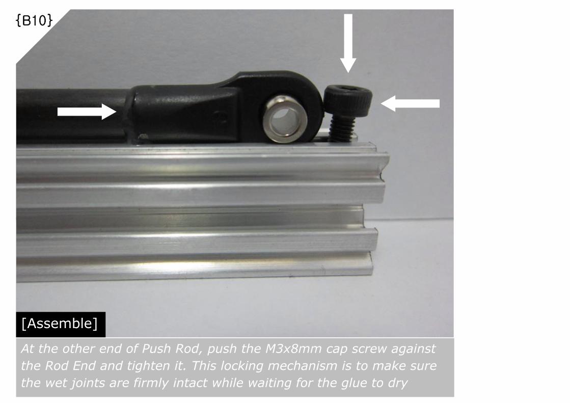
[Assemble]
At the other end of Push Rod, push the M3x8mm cap screw against
the Rod End and tighten it. This locking mechanism is to make sure
the wet joints are firmly intact while waiting for the glue to dry
{B10}
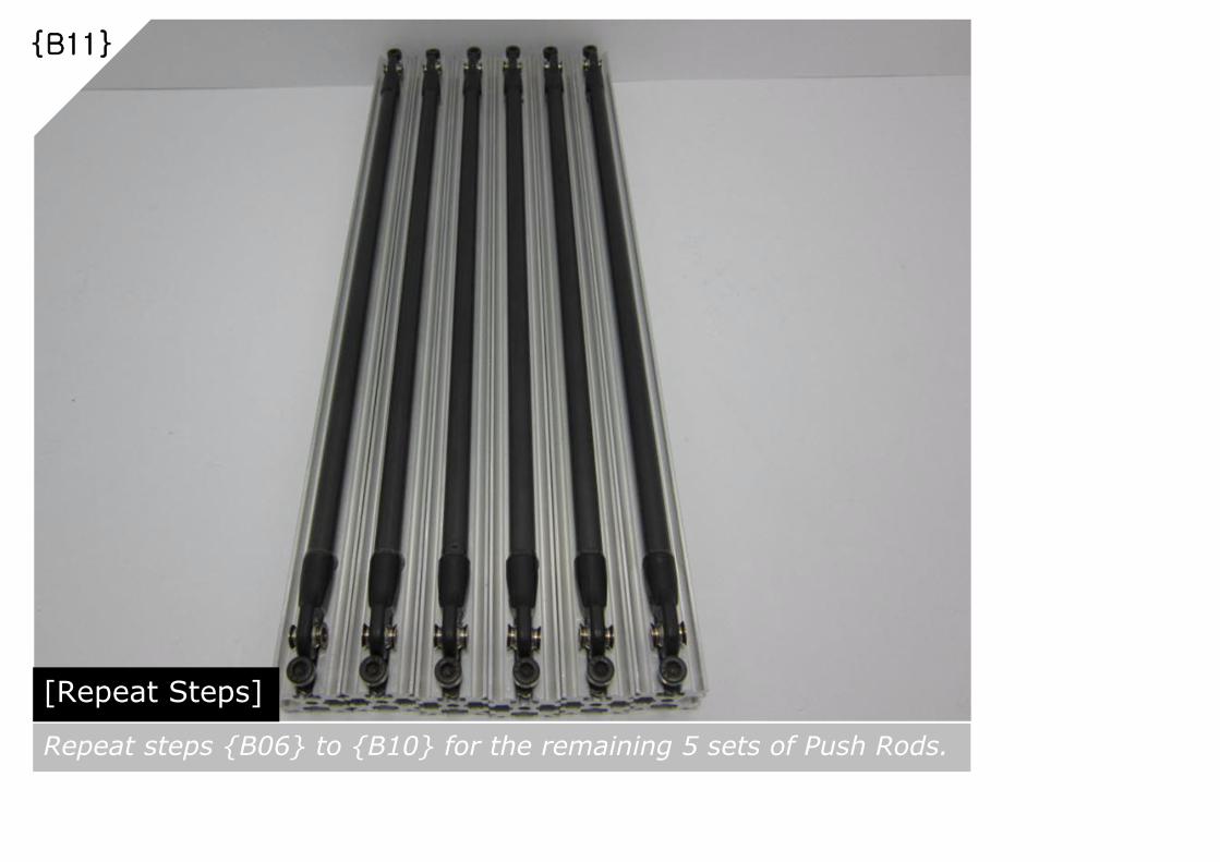
[Repeat Steps]
Repeat steps {B06} to {B10} for the remaining 5 sets of Push Rods.
{B11}

!!! The most important aspect of Push Rod assembly is to have all of
them assembled and aligned to the same length, end-to-end.
A simple verification method as shown above can help to isolate the
odd one out and readjust the wet joints before they are fully dried.
{B12}
[End-to-End Alignment]

{B13}
[Remove Push Rods from Assembly Jigs]
Once the glue dried up over night and solid bond has formed,
remove the assembled Push Rods from the Assembly Jigs. You
should expect the same end-to-end length for all the Push Rods

Let’s Frame It Up
Assemble the Main Body Frame
Note: Advisable to complete all the assembly related to the Vertical Frames before attaching
the Top Frame
{C}

{C01}
M3 Nut = 10 pcs
M3 x 8mm Cap Screw = 10 pcs
[Prepare Parts]
Parts required for a single Bottom Vertex assembly
Bottom Vertex = 1 pc
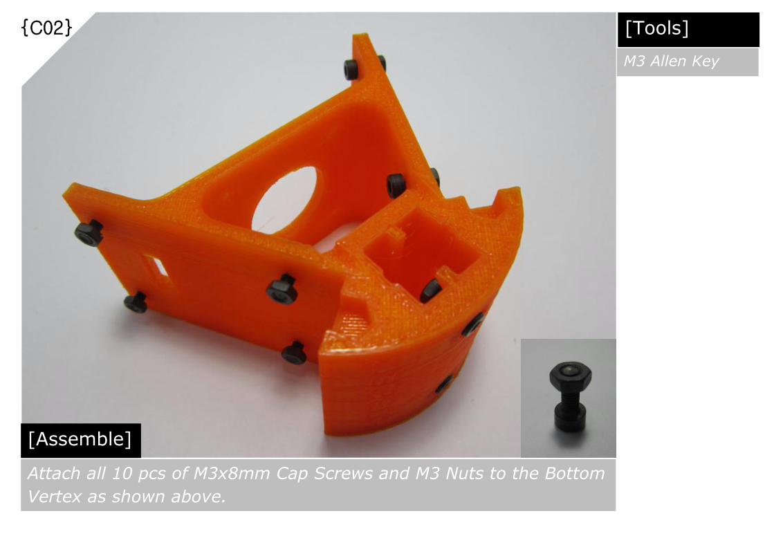
{C02}
[Assemble]
Attach all 10 pcs of M3x8mm Cap Screws and M3 Nuts to the Bottom
Vertex as shown above.
[Tools]
M3 Allen Key

{C03}
[Repeat Steps]
Repeat steps {C01} to {C02}. Total 3 sets of assembled Bottom
Vetexes needed as shown above.
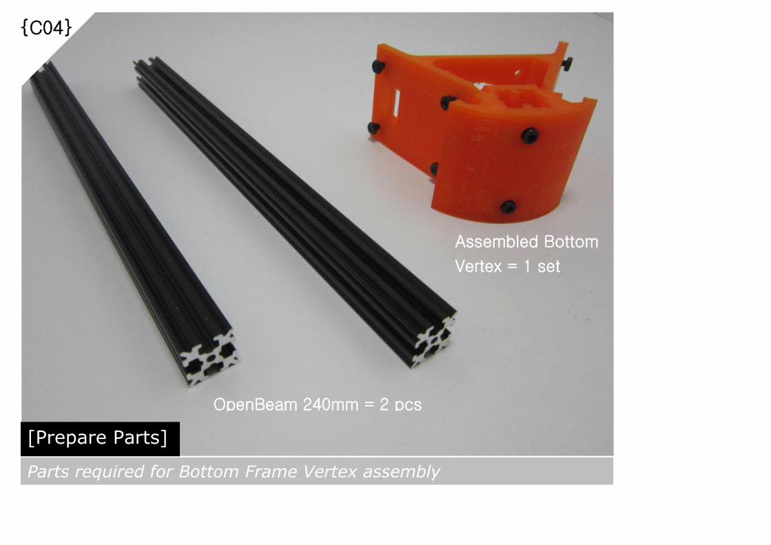
{C04}
[Prepare Parts]
Parts required for Bottom Frame Vertex assembly
OpenBeam 240mm = 2 pcs
Assembled Bottom
Vertex = 1 set

{C05}
[Align and Slot In]
Align the M3 Nuts at one side of the Bottom Vertex assembly to the
opening of OpenBeam slot guide and slot them in all the way to the
end.

{C06}
[Tighten the Screws]
Fasten both OpenBeams which are in correct position by tightening
the M3 Cap Screws as shown above.
[Tools]
M3 Allen Key
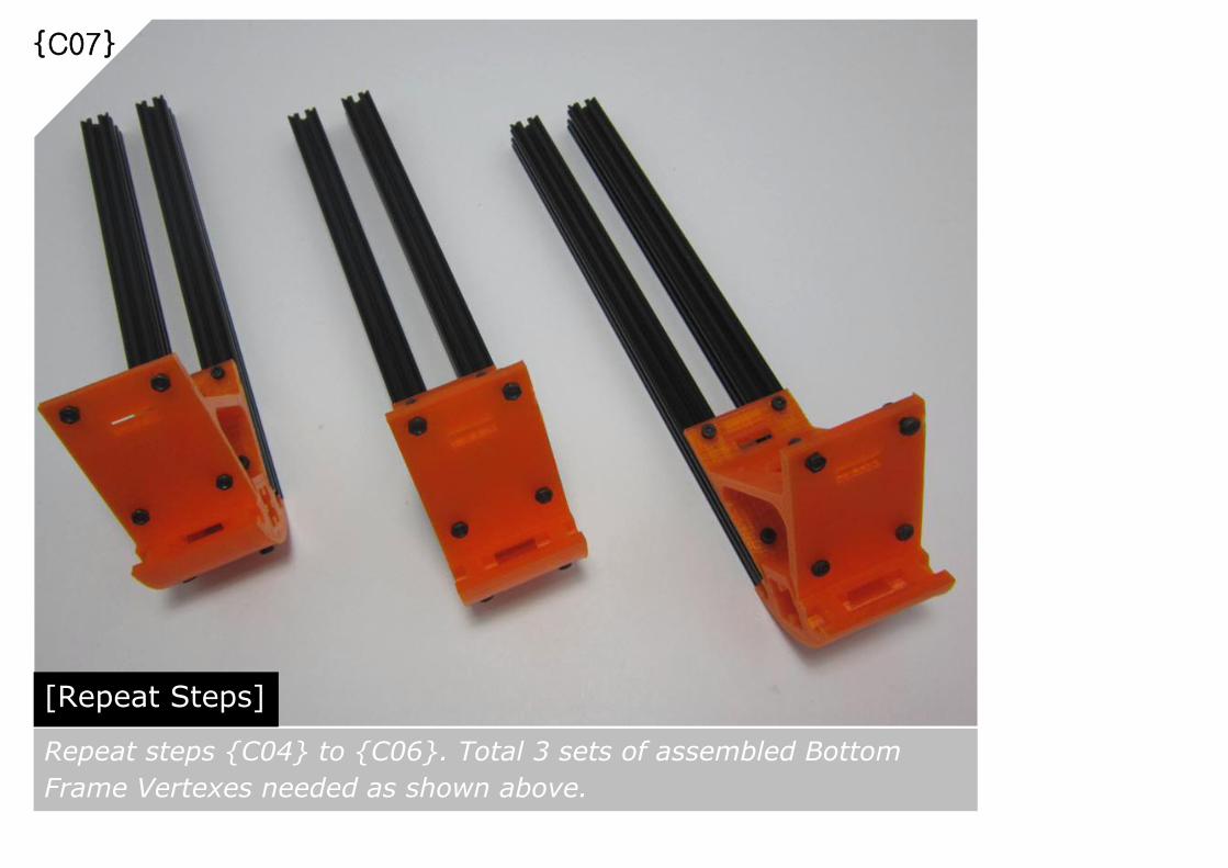
{C07}
[Repeat Steps]
Repeat steps {C04} to {C06}. Total 3 sets of assembled Bottom
Frame Vertexes needed as shown above.

{C08}
[Prepare Parts]
Parts required for Bottom Frame assembly
Assembled Bottom
Frame Vertex = 3 sets

{C09}
[Align and Slot In]
Align the M3 Nuts at the opened side of the assembled Bottom Frame
Vertexes to the opening of OpenBeam slot guide and slot them in all
the way to the end.

{C10}
[Tighten the Screws]
Fasten the newly slotted in OpenBeams which are in correct position
by tightening the M3 Cap Screws as shown above.
[Tools]
M3 Allen Key

{C11}
[Inspection]
Place the completed Bottom Frame on flat surface and make sure the
bottom part is perfectly even
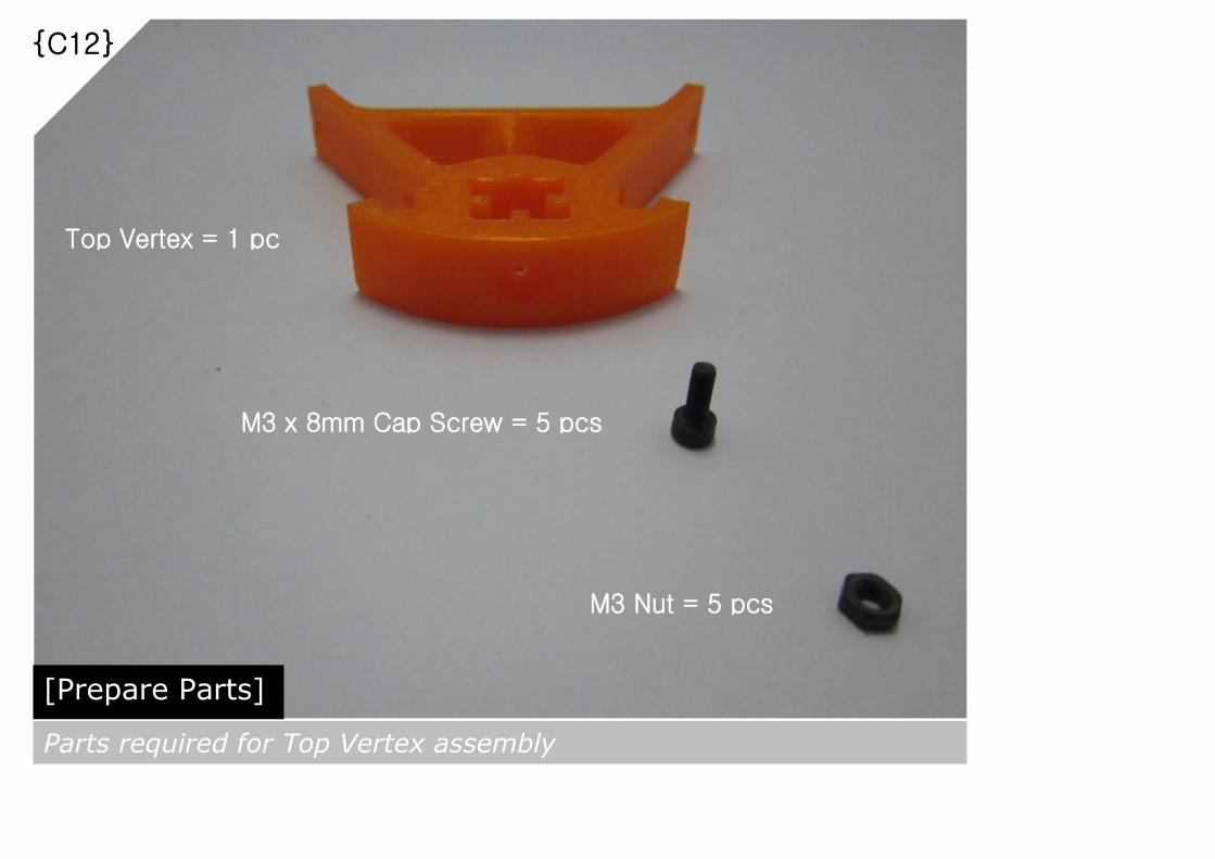
{C12}
[Prepare Parts]
Parts required for Top Vertex assembly
M3 Nut = 5 pcs
M3 x 8mm Cap Screw = 5 pcs
Top Vertex = 1 pc

{C13}
[Assemble]
Attach all 5 pcs of M3x8mm Cap Screws and M3 Nuts to the Top
Vertex as shown above.
[Tools]
M3 Allen Key
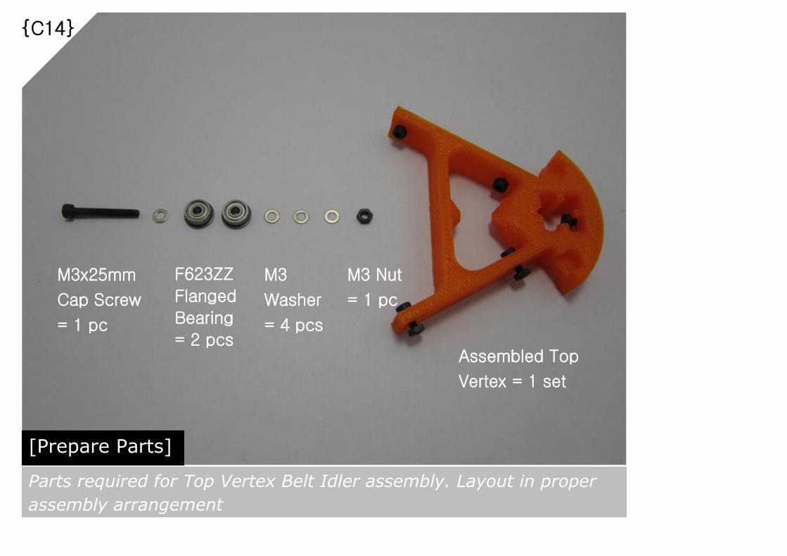
{C14}
[Prepare Parts]
Parts required for Top Vertex Belt Idler assembly. Layout in proper
assembly arrangement
Assembled Top
Vertex = 1 set
M3x25mm
Cap Screw
= 1 pc
F623ZZ
Flanged
Bearing
= 2 pcs
M3
Washer
= 4 pcs
M3 Nut
= 1 pc
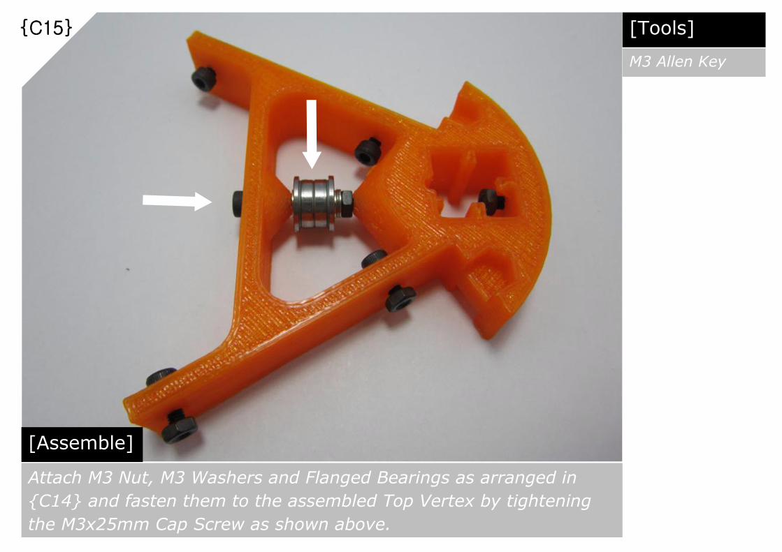
{C15}
[Assemble]
Attach M3 Nut, M3 Washers and Flanged Bearings as arranged in
{C14} and fasten them to the assembled Top Vertex by tightening
the M3x25mm Cap Screw as shown above.
[Tools]
M3 Allen Key

{C16}
[Repeat Steps]
Repeat steps {C12} to {C15}. Total 3 sets of assembled Top
Vertexes with Belt Idlers needed as shown above.

{C17}
[Prepare Parts]
Parts required for Top Frame Vertex assembly.
Assembled Top Vertex
with Belt Idler = 1 set OpenBeam 240mm = 1 pc
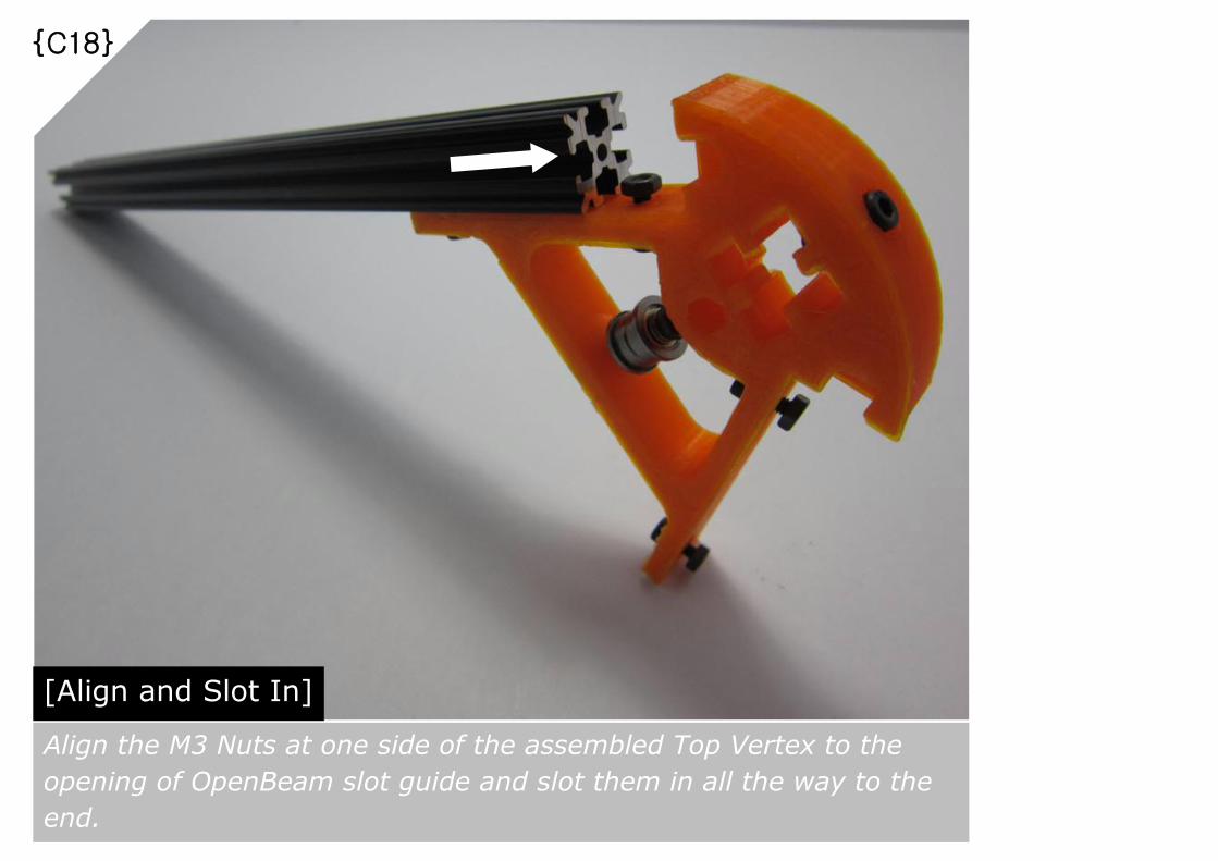
{C18}
[Align and Slot In]
Align the M3 Nuts at one side of the assembled Top Vertex to the
opening of OpenBeam slot guide and slot them in all the way to the
end.

{C19}
[Tighten the Screws]
Fasten both OpenBeams which are in correct position by tightening
the M3 Cap Screws as shown above.
[Tools]
M3 Allen Key

{C20}
[Repeat Steps]
Repeat steps {C17} to {C19}. Total 3 sets of assembled Top Frame
Vertexes needed as shown above.
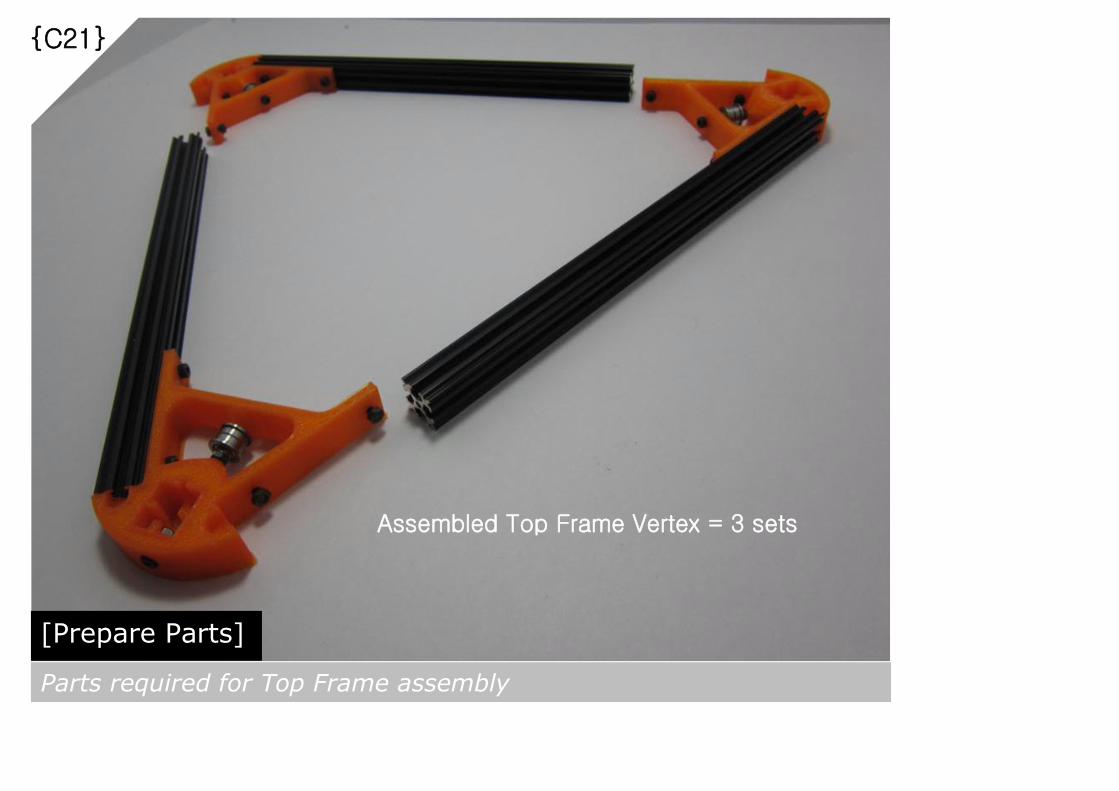
{C21}
[Prepare Parts]
Parts required for Top Frame assembly
Assembled Top Frame Vertex = 3 sets

{C22}
[Align and Slot In]
Align the M3 Nuts at the opened side of the assembled Top Frame
Vertexes to the opening of OpenBeam slot guide and slot them in all
the way to the end.
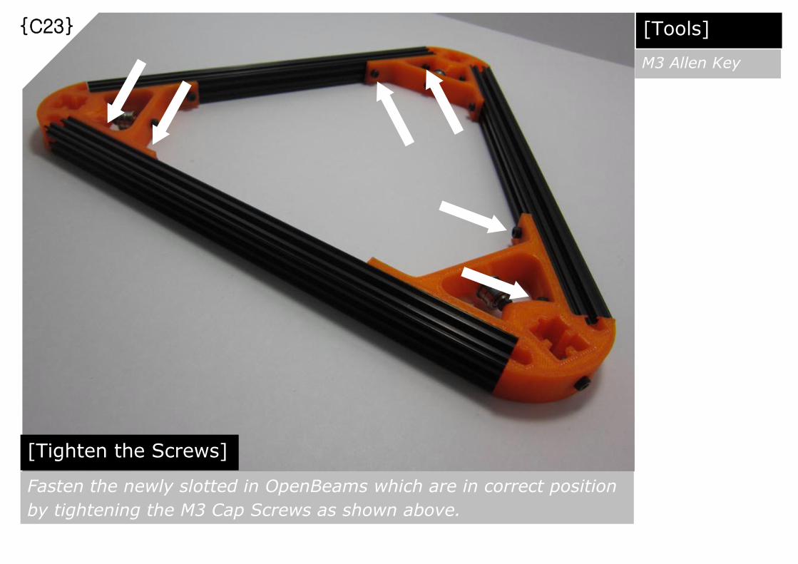
{C23}
[Tighten the Screws]
Fasten the newly slotted in OpenBeams which are in correct position
by tightening the M3 Cap Screws as shown above.
[Tools]
M3 Allen Key

{C24}
[Inspection]
Place the completed Top Frame on top of the Bottom Frame and
make sure they are perfectly aligned at the vertex points and as well
as the edges

{C25}
[Prepare Parts]
Parts required for Vertical Frame assembly
Assembled
Bottom
Frame = 1 pc
OpenBeam 600mm = 3 pcs

{C26}
[Align and Slot In]
Align the OpenBeam Vertical Frame slot guide to the M3 Nuts inside
one of the assembled Bottom Frame Vertex’s vertical frame opening
and slot it in all the way to the end.

{C27}
[Tighten the Screws]
Once the OpenBeam Vertical Frame fully slotted in, secure it by
tightening the M3 Cap Screws as shown above.
[Tools]
M3 Allen Key
View from below
Vertical Frame
fully slotted in
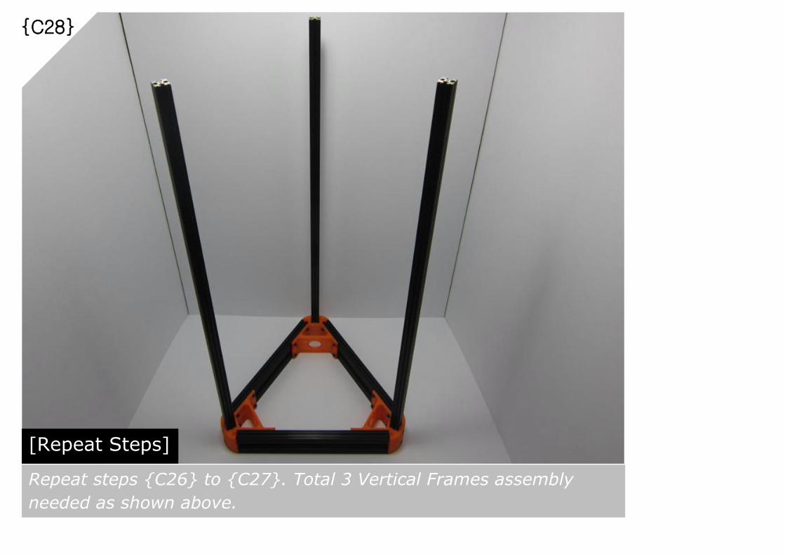
{C28}
[Repeat Steps]
Repeat steps {C26} to {C27}. Total 3 Vertical Frames assembly
needed as shown above.
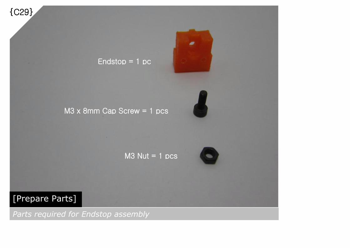
{C29}
[Prepare Parts]
Parts required for Endstop assembly
M3 Nut = 1 pcs
M3 x 8mm Cap Screw = 1 pcs
Endstop = 1 pc

{C30}
[Assemble]
Attach M3x8mm Cap Screws and M3 Nuts to the Endstop as shown
above.
[Tools]
M3 Allen Key

{C31}
[Repeat Steps]
Repeat steps {C29} to {C30}. Total 6 sets of Endstops assembly
needed as shown above.
[Tools]
M3 Allen Key

{C32}
Slot in 3pcs of Endstops assembly with flat side facing up as shown
above. Temporarily fasten the Endstops assembly to the Vertical
Frame. To be fully tightened after Linear Rail attachment completed.
[Tools]
M3 Allen Key
[Slot In and Position]

{C33}
[Prepare Parts]
Parts required for Linear Rail assembly
M3 Nut = 16 pcs
M3 x 8mm Cap Screw = 16 pcs
Linear Rail 400mm = 1 pc
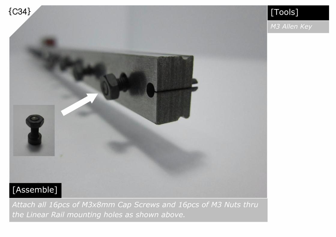
{C34}
[Assemble]
Attach all 16pcs of M3x8mm Cap Screws and 16pcs of M3 Nuts thru
the Linear Rail mounting holes as shown above.
[Tools]
M3 Allen Key

{C35}
[Repeat Steps]
Repeat steps {C33} to {C34}. Total 3 sets of Linear Rail assembly
needed as shown above.

{C36}
[Prepare Parts]
Parts required for Linear Rail to Vertical Frame assembly
Assembled Bottom
and Vertical Frame
= 1 set
Assembled Linear Rail 400mm = 3 sets

{C37}
Slot in the assembled 400mm Linear Rail set to the Vertical Frame as shown above.
The suggested positioning is based on the dimensions of moving parts supplied as
well as required linear motion space at lower end, eg. During auto bed leveling etc
[Slot In and Position]
Suggested distance
from Top of 400mm
Linear Rail to Top of
Vertical Frame = 70mm

{C38}
[Tighten the Screws]
!!!Once making sure that all 3 sets of Linear Rail having the same
positioning on the Vertical Frame, secure them by tightening all 48
pcs of M3x20mm Cap Screws.
[Tools]
M3 Allen Key
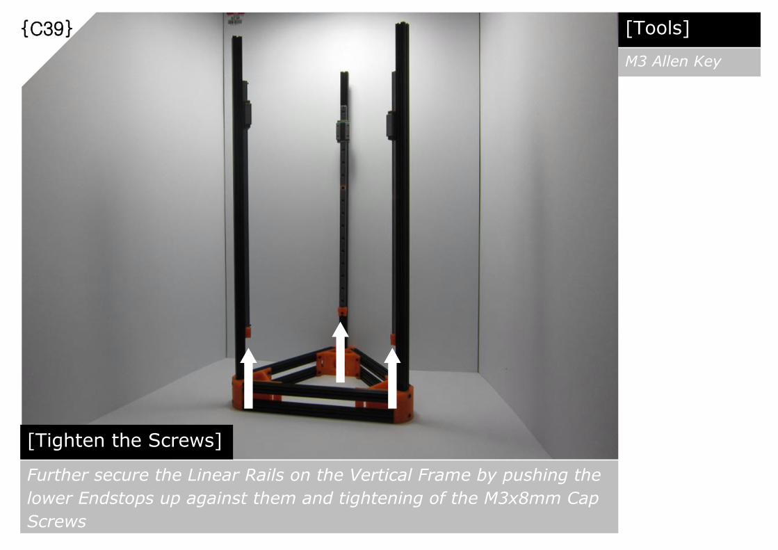
{C39}
[Tighten the Screws]
Further secure the Linear Rails on the Vertical Frame by pushing the
lower Endstops up against them and tightening of the M3x8mm Cap
Screws
[Tools]
M3 Allen Key

{C40}
[Prepare Parts]
Parts required for Upper Endstops attachment to Vertical Frame
Assembled Bottom
and Vertical Frame
with Linear Rails
Attached = 1 set
Assembled Endstops = 3 sets

{C41}
[Slot In and Tighten the Screws]
Slot in the upper Endstops with flat side facing down and push them
down against the Linear Rail. Tighten the M3x8mm Cap Screws
[Tools]
M3 Allen Key

{C42}
[Prepare Parts]
Parts required for Extruder Motor Holder assembly
M3 Nut = 2 pcs
M3 x 8mm Cap Screw = 2 pcs
Extruder Motor Holder = 1 pc

{C43}
[Assemble]
Attach all 2pcs of M3x8mm Cap Screws and 2pcs of M3 Nuts thru the
Extruder Motor Holder mounting holes as shown above.
[Tools]
M3 Allen Key
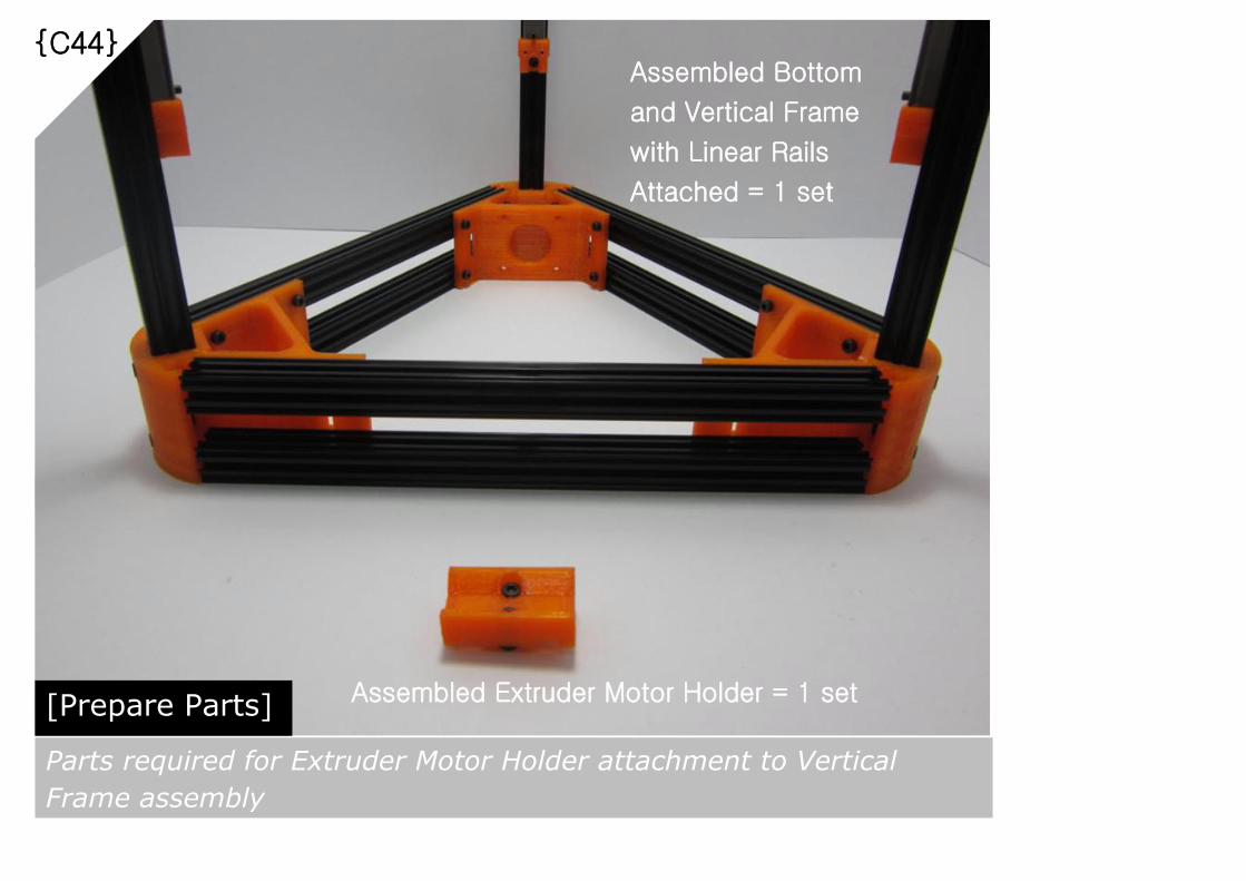
{C44}
[Prepare Parts]
Parts required for Extruder Motor Holder attachment to Vertical
Frame assembly
Assembled Bottom
and Vertical Frame
with Linear Rails
Attached = 1 set
Assembled Extruder Motor Holder = 1 set

{C45}
[Slot In and Position]
Slot in the assembled Extruder Motor Holder set into one of the
Vertical Frame as shown above. Position it at the mid-point of the
Vertical Frame. Tighten the M3x8mm Cap Screws
[Tools]
M3 Allen Key

{C46}
[Prepare Parts]
Parts required for Vertical Carriage assembly
M3 x 8mm Cap Screw = 2 pcs
Vertical Carriage = 1 pc
M3 x 16mm Cap Screw = 2 pcs

{C47}
[Assemble]
Insert 2pcs of M3x16mm Cap Screws into upper screw holes and
2pcs of M3x8mm Cap Screws into lower screw holes as shown above.

{C48}
[Repeat Steps]
Repeat steps {C46} to {C47}. Total 3 sets of Vertical Carriage
assembly needed as shown above.
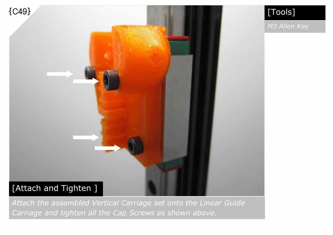
{C49}
[Attach and Tighten ]
Attach the assembled Vertical Carriage set onto the Linear Guide
Carriage and tighten all the Cap Screws as shown above.
[Tools]
M3 Allen Key
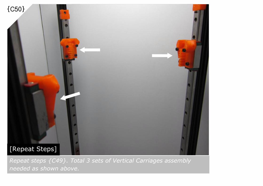
{C50}
[Repeat Steps]
Repeat steps {C49}. Total 3 sets of Vertical Carriages assembly
needed as shown above.

{C51}
[Prepare Parts]
Parts required for Vertical Carriage assembly
M3 Nylon
Lock Nuts
= 6 pcs

{C52}
[Insert Nylon Lock Nuts] Slot in 2pcs of Nylon Lock Nuts into Vertical Carriage as shown
above. Repeat the same for remaining Vertical Carriages.

{C53}
[Prepare Parts]
Parts required for Top Frame to Vertical Frame assembly
Assembled Bottom
and Vertical Frame
with Linear Rails
Attached = 1 set
Assembled
Top Frame
= 1 set

{C54}
[Slot In and Position]
Slot in the assembled Top Frame and position it 15mm below the Top
of Vertical Frame at each vertex as shown above. Gently tighten the
M3x8mm Cap Screws at each vertex once the Top Frame in position
15mm

{C55}
[Prepare Parts]
Parts required for Belt Tensioner assembly
M3 Nut
= 1 pc
M3x35mm
Cap Screw
= 1 pc
M3
Washer
= 1 pc

{C56}
[Slot In]
Slot in the assembled Belt Tensioner Screw as shown above.

{C57}
[Attach]
Attach M3 Nut to the Belt Tensioner Screw as shown above.
{C58}
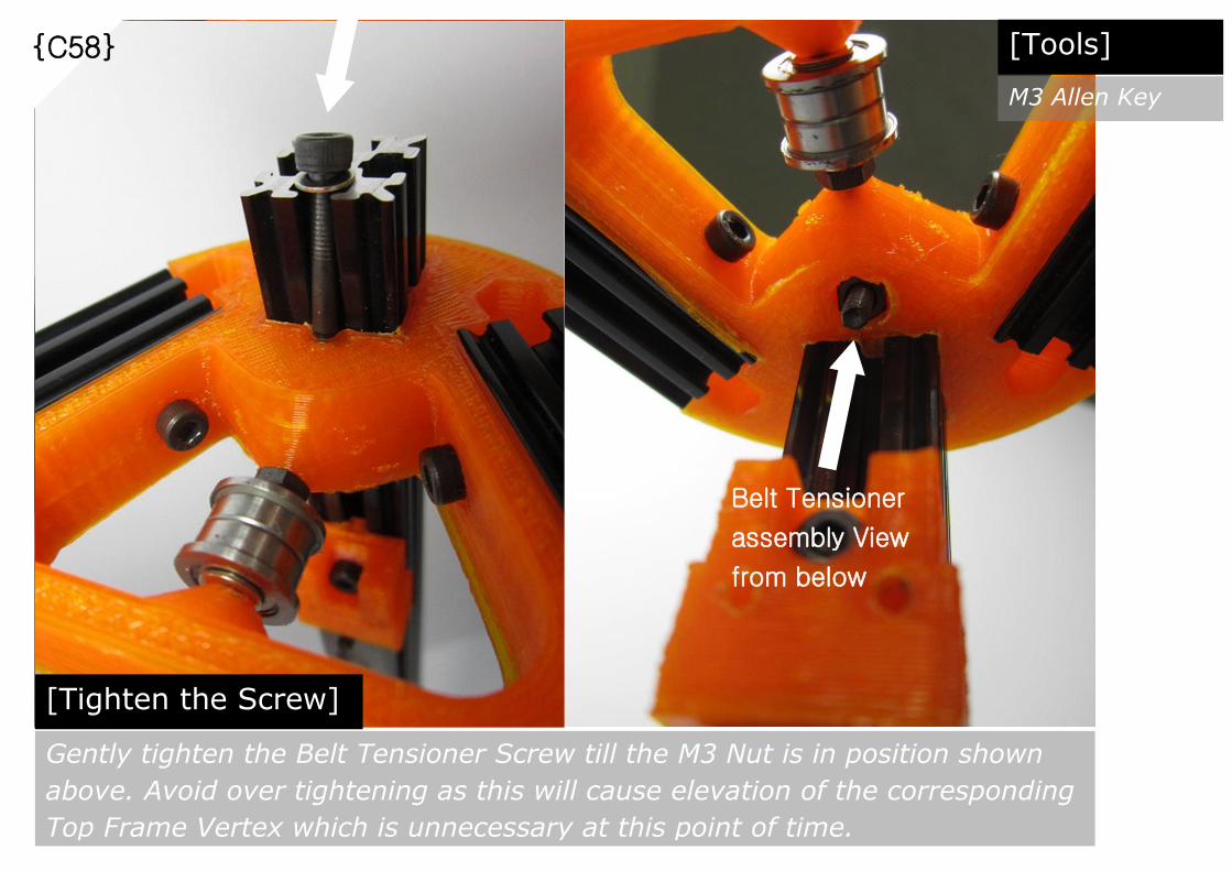
[Tighten the Screw]
Gently tighten the Belt Tensioner Screw till the M3 Nut is in position shown
above. Avoid over tightening as this will cause elevation of the corresponding
Top Frame Vertex which is unnecessary at this point of time.
Belt Tensioner
assembly View
from below
[Tools]
M3 Allen Key

{C59}
[Repeat Steps]
Repeat Steps {C55} to {C58} for the remaining 2 vertexes.
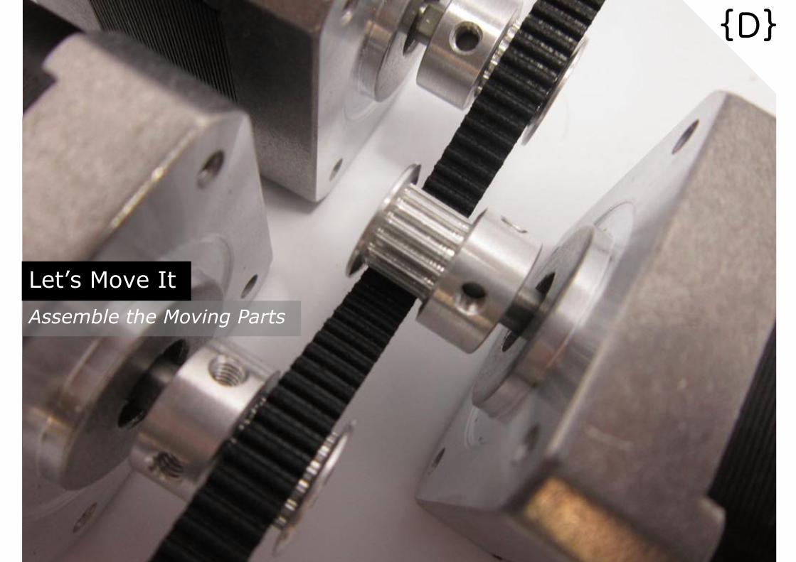
Let’s Move It
Assemble the Moving Parts
{D}

GT2 Aluminium 16 Teeth Pulley = 1 pc
NEMA17 Stepper Motor = 1 pc
Set Screw = 2 pcs
{D01}
[Prepare Parts]
Parts required for Stepper Motor Assembly
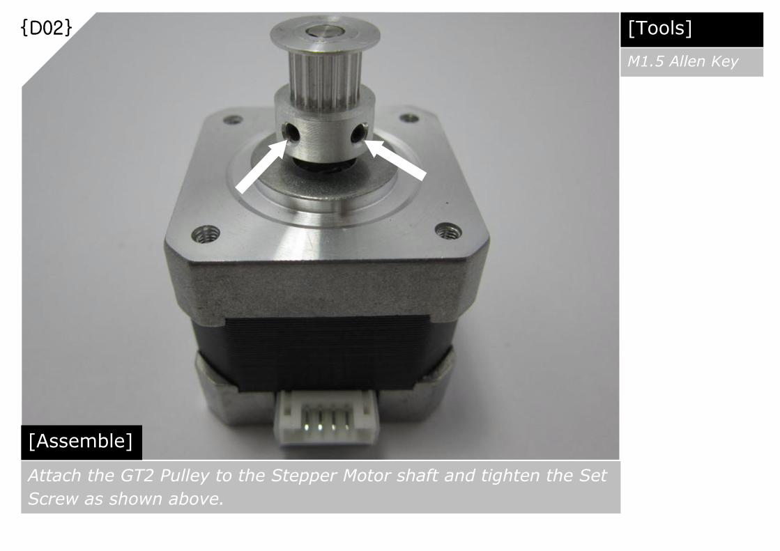
{D02}
[Assemble]
Attach the GT2 Pulley to the Stepper Motor shaft and tighten the Set
Screw as shown above.
[Tools]
M1.5 Allen Key
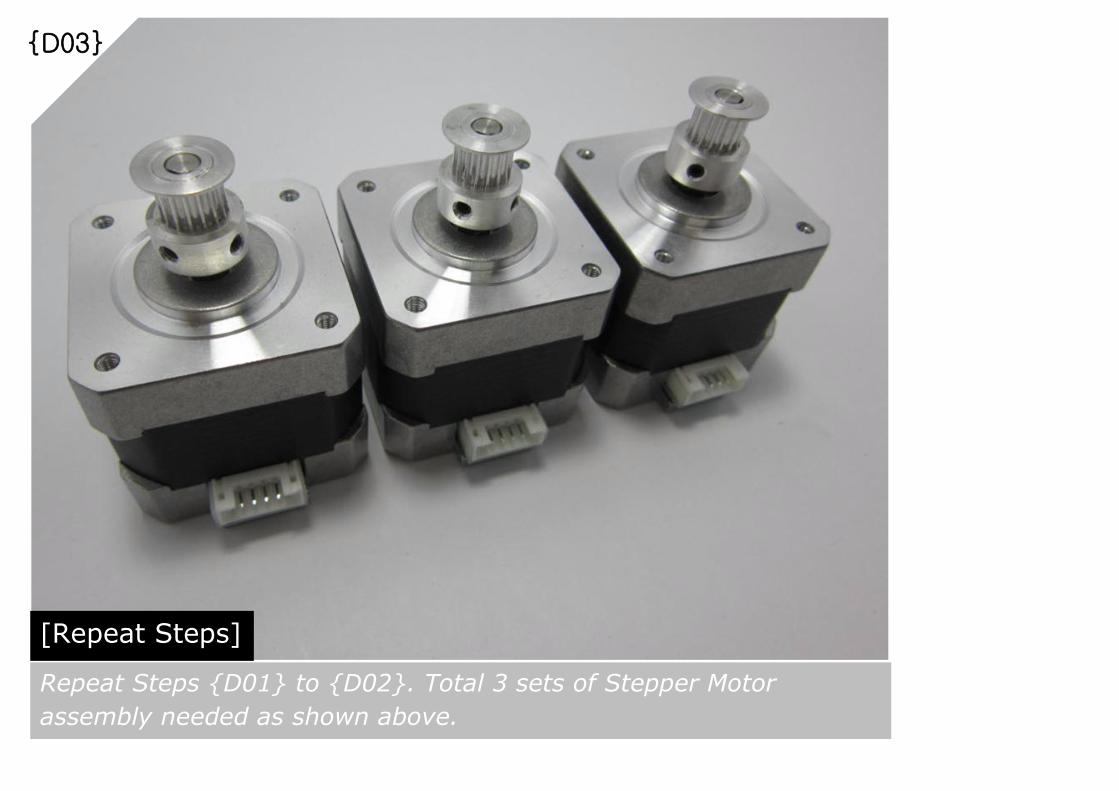
{D03}
[Repeat Steps]
Repeat Steps {D01} to {D02}. Total 3 sets of Stepper Motor
assembly needed as shown above.

{D04}
[Prepare Parts]
Parts required for Vertical Linear Motion Stepper Motor mounting to
the assembled Main Body Frame
M3x8mm
Cap Screw
= 12 pcs
Assembled
Stepper Motor
= 3 sets
Assembled
Main Body
Frame = 1 set
{D05}
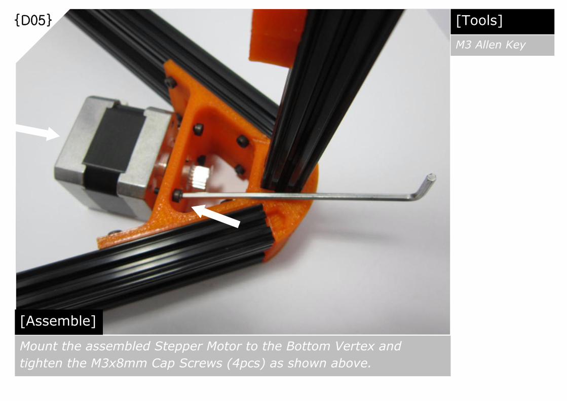
[Assemble]
Mount the assembled Stepper Motor to the Bottom Vertex and
tighten the M3x8mm Cap Screws (4pcs) as shown above.
[Tools]
M3 Allen Key

{D06}
[Repeat Steps]
Repeat Steps {D05}. Total 3 sets of Vertical Linear Motion Stepper
Motors needed as shown above.

{D07}
[Prepare Parts]
Parts required for Vertical Linear Motion Drive Belt assembly.
Note: 4000mm Open Ended GT2 Belt supplied in the kit. Cut it
into 3 pcs.
Open Ended GT2 Belt 1300mm = 1 pc

{D08}
[Assemble]
Position the Vertical Carriage at the top end of Linear Rail and guide
one end of the open ended GT2 belt into Vertical Carriage belt clamp
as shown above.
40mm
{D09}
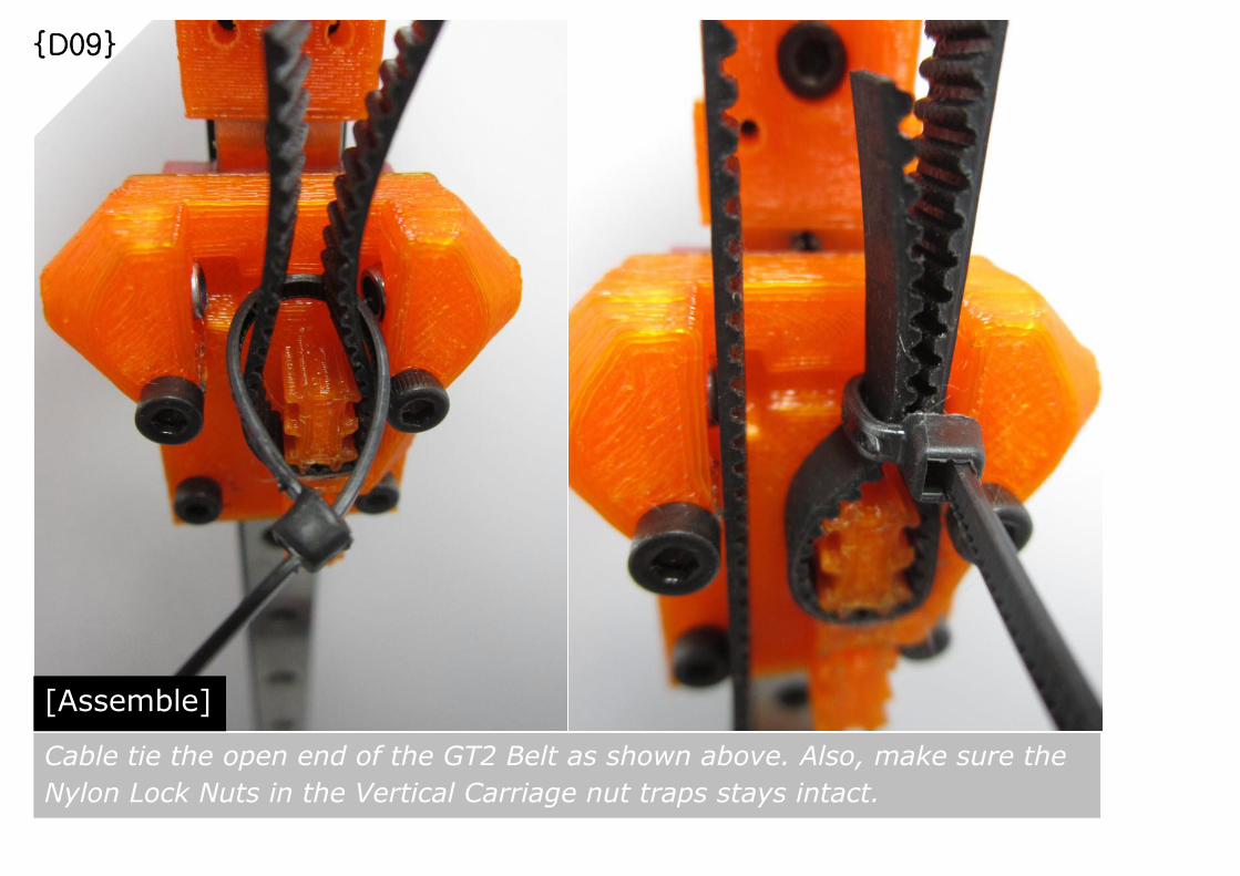
[Assemble]
Cable tie the open end of the GT2 Belt as shown above. Also, make sure the
Nylon Lock Nuts in the Vertical Carriage nut traps stays intact.

{D10}
[Assemble]
Loop the GT2 Belt over the Belt Idler’s Flanged Bearing, and pull it
downwards. Then loop it over the GT2 Pulley and pull it upward as shown
above. The Vertical Carriage should stays anchored during pulling actions
Pull
down
Pull
Up

{D11}
[Assemble]
Pull the GT2 Belt tight and guide it into the lower belt clamp of the Vertical
Carriage as shown above
Pull
Tight

{D12}
[Assemble]
Fasten the opened end of the GT2 Belt with cable tie as shown above. Trim
off excess length of GT2 Belt at both ends. Suggest to reserve around 40mm
of excess GT2 Belt length at lower end of Vertical Carriage. Secure it with
cable tie. This is just in case future modifications needed.
40mm

{D13}
[Repeat Steps]
Repeat Steps {D07} to {D12}. Total 3 sets of Vertical Linear Motion
Drive Belts assembly needed as shown above. Upon completion,
lubricate the Linear Rail to ensure smooth operation during printing

{D14}
[Inspections]
Gently tighten the M3x8mm Cap Screws at each Top Vertex. In case
GT2 Belt tension not ideal, tighten the Belt Tensioner Cap Screw for
better Belt Tension.
[Tools]
M3 Allen Key

M3 Nylon Lock Nuts = 6 pcs
Effector = 1 pc
{D15}
[Prepare Parts]
Parts required for Effector assembly

{D16}
[Assemble]
Thread the M3x25mm Cap Screw thru the ball joint mounting hole
and attach an M3 Nylon Lock Nut as shown above.
[Tools]
M3x25mm Cap
Screw
{D17}
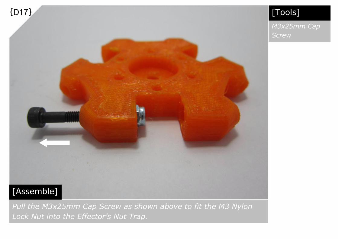
[Assemble]
Pull the M3x25mm Cap Screw as shown above to fit the M3 Nylon
Lock Nut into the Effector’s Nut Trap.
[Tools]
M3x25mm Cap
Screw

{D18}
[Repeat Steps]
Repeat Steps {D16} to {D17}. The completed Effector assembly is
as shown above.

{D19}
[Prepare Parts]
Parts required for Effector & Push Fit Connector assembly
Push Fit Connector = 1 pc
Assembled Effector = 1 set
[Tools]
M5 Tap Drill
{D20}
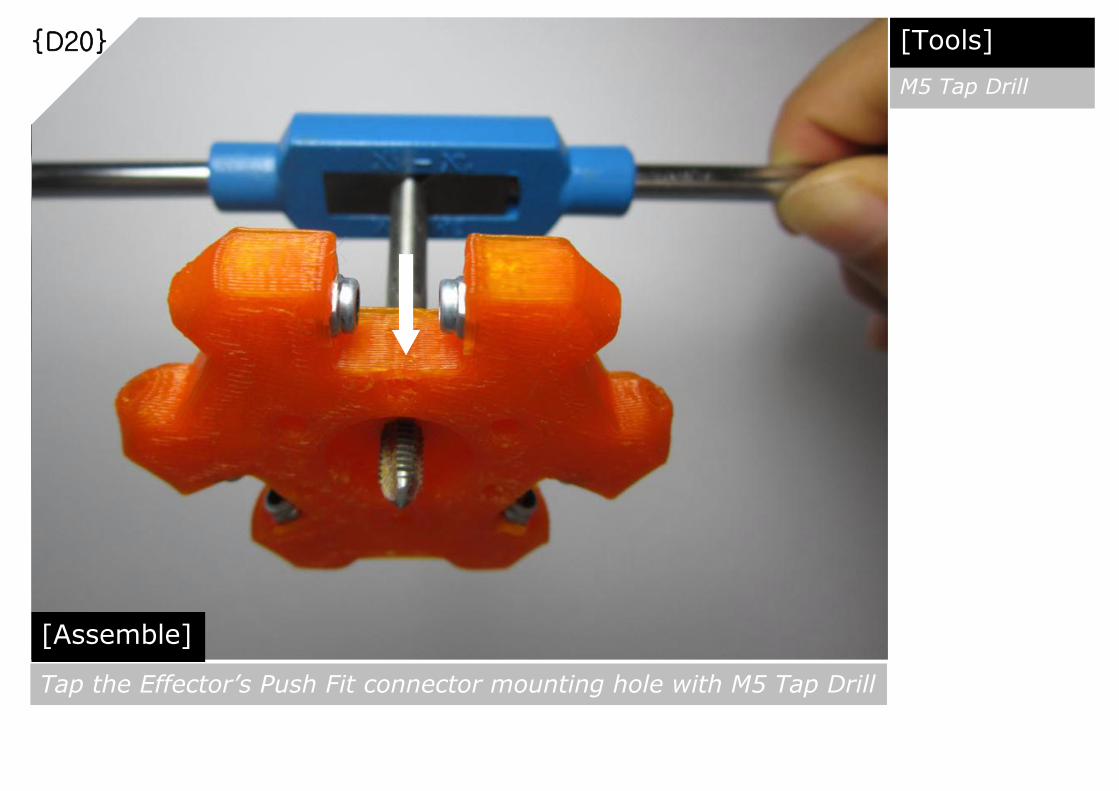
[Assemble]
Tap the Effector’s Push Fit connector mounting hole with M5 Tap Drill
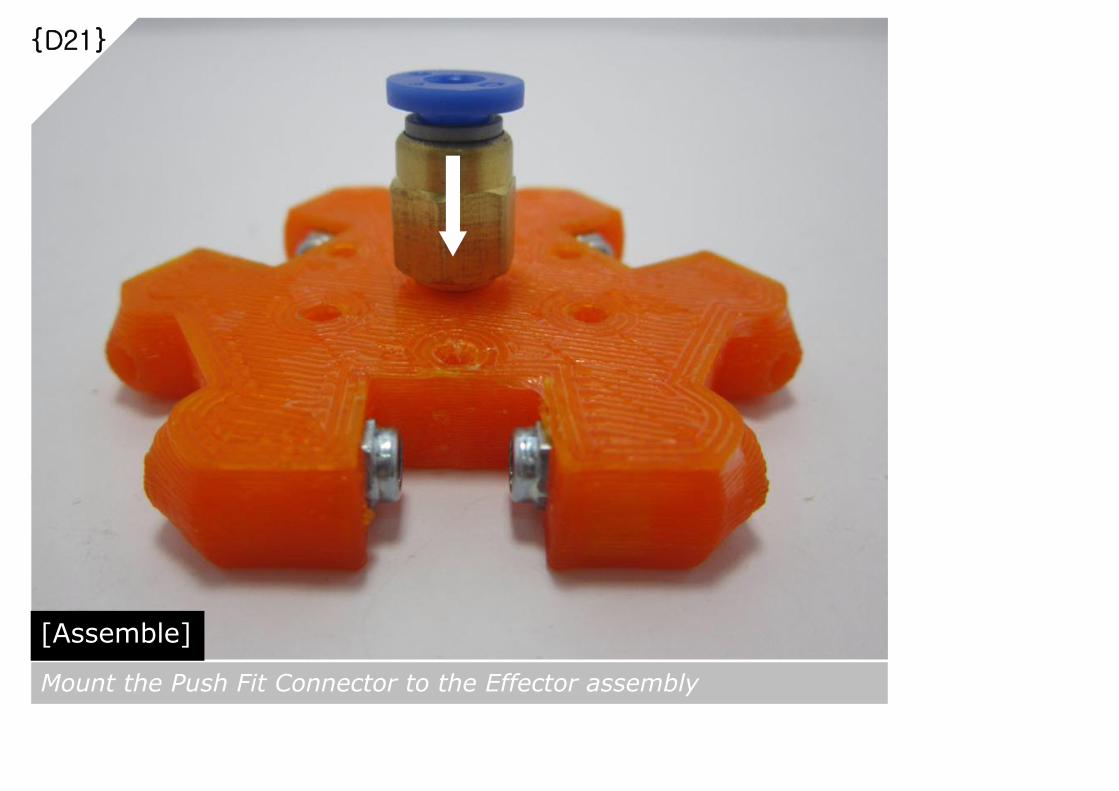
{D21}
[Assemble]
Mount the Push Fit Connector to the Effector assembly
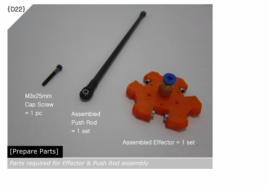
{D22}
[Prepare Parts]
Parts required for Effector & Push Rod assembly
Assembled Effector = 1 set
Assembled
Push Rod
= 1 set
M3x25mm
Cap Screw
= 1 pc

{D23}
[Assemble]
Thread the M3x25mm Cap Screw into the Push Rod Ball Joint as
shown above
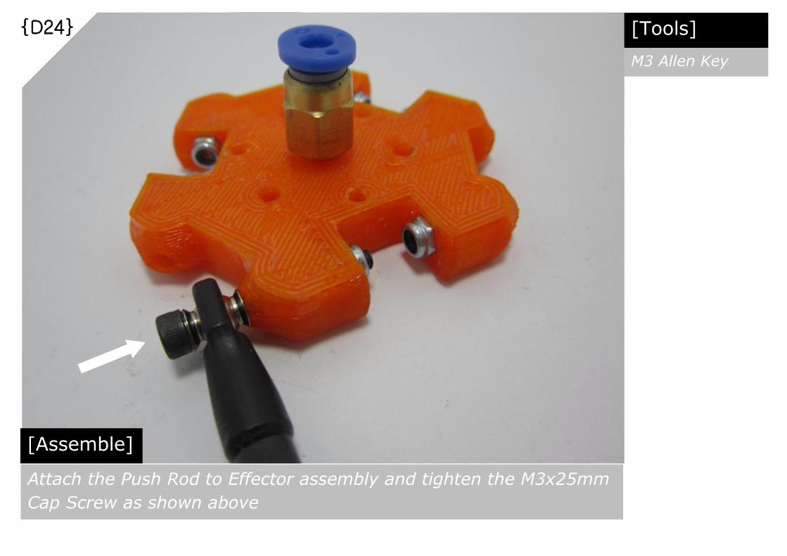
{D24}
[Assemble]
Attach the Push Rod to Effector assembly and tighten the M3x25mm
Cap Screw as shown above
[Tools]
M3 Allen Key

{D25}
[Repeat Steps]
Repeat Steps {D22} to {D24}. The completed assembly should have
all 6 sets of Push Rods attached to the Effector as shown above.

{D26}
[Prepare Parts]
Parts required for Push Rod to Vertical Carriage assembly
M3x20mm
Cap Screw
= 6 pcs

{D27}
[Assemble]
Attach the Push Rod Ball Joint to the Vertical Carriage’s ball joint
mount and tighten the M3x20mm Cap Screw as shown above.
[Tools]
M3 Allen Key

{D28}
[Repeat Steps]
Repeat Steps {D27} to attach remaining Push Rods to the rest of
Vertical Carriages as shown above.
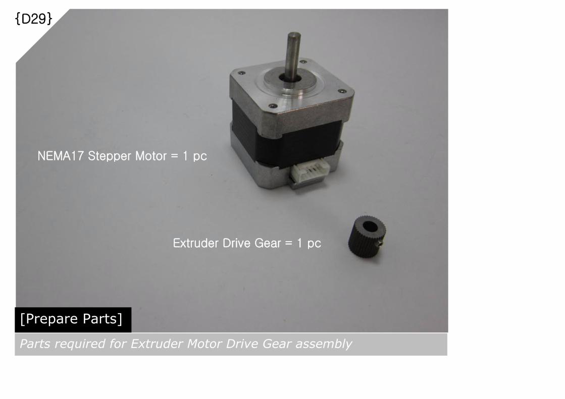
{D29}
[Prepare Parts]
Parts required for Extruder Motor Drive Gear assembly
NEMA17 Stepper Motor = 1 pc
Extruder Drive Gear = 1 pc
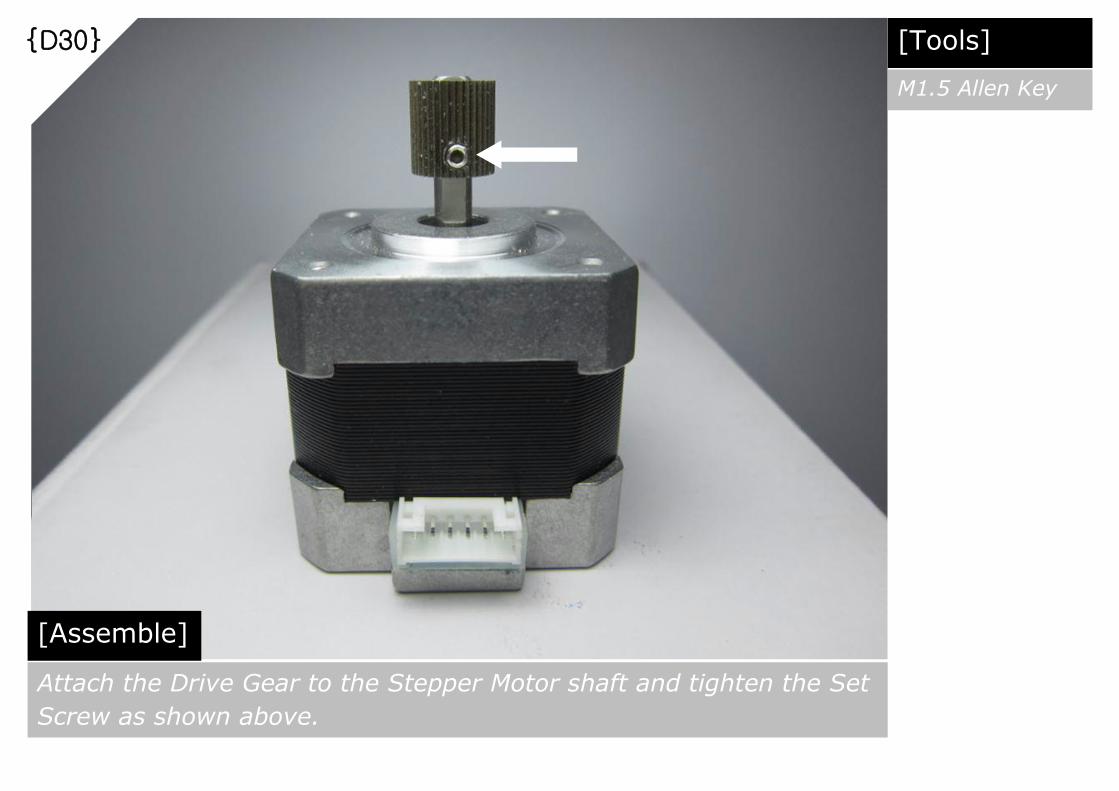
{D30}
[Assemble]
Attach the Drive Gear to the Stepper Motor shaft and tighten the Set
Screw as shown above.
[Tools]
M1.5 Allen Key

{D31}
[Prepare Parts]
Parts required for Extruder Motor Adaptor assembly
Extruder Motor Adaptor = 1 pc
625ZZ Bearing = 1 pc
M5 Nut = 1 pc
M5x20mm Cap Screw = 1 pc

{D32}
[Assemble]
Insert the M5 Nut into the nut trap as shown above.
[Tools]
M5 Allen Key

{D33}
[Assemble]
Insert the 625ZZ Bearing into the bearing mount and secure it with M5x20mm Cap
Screw as shown above. In case the 625ZZ Bearing not able to rotate freely,
reattempt this step after remove remaining support material from bearing mount
[Tools]
M5 Allen Key

{D34}
[Prepare Parts]
Parts required for Extruder Motor Adaptor Mount assembly
Assembled Extruder Motor = 1 set
Assembled Extruder Motor Adaptor = 1 set
M3x8mm Cap Screw = 3 pcs

{D35}
[Assemble]
Mount the Assembled Extruder Adaptor to the Stepper Motor and
secure it with M3x8mm Cap Screws as shown above.
[Tools]
M3 Allen Key

{D36}
Assembled Extruder Motor = 1 set
M3 Nut = 1 pc
M3x20mm Cap Screw = 1 pc
[Prepare Parts]
Parts required for Extruder Motor Adaptor Clamp assembly
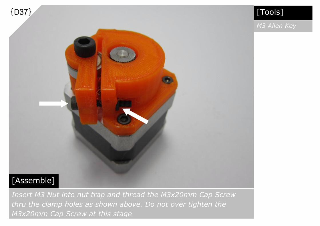
{D37}
[Assemble]
Insert M3 Nut into nut trap and thread the M3x20mm Cap Screw
thru the clamp holes as shown above. Do not over tighten the
M3x20mm Cap Screw at this stage
[Tools]
M3 Allen Key

{D38}
[Prepare Parts]
Parts required for Extruder Motor Adaptor Clamp assembly
Assembled Extruder Motor = 1 set
Push Fit Connector = 1 pc
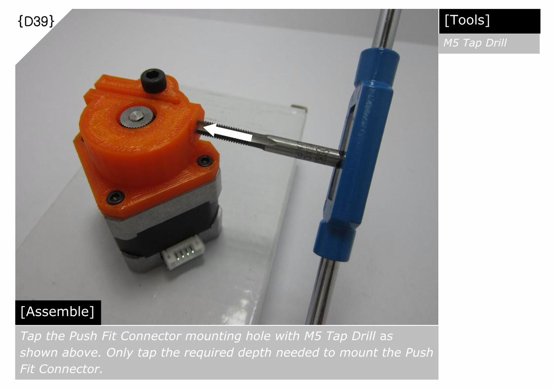
{D39}
[Assemble]
Tap the Push Fit Connector mounting hole with M5 Tap Drill as
shown above. Only tap the required depth needed to mount the Push
Fit Connector.
[Tools]
M5 Tap Drill

{D40}
[Assemble]
Mount the Push Fit Connector as shown above.

{D41}
[Assemble]
Mount the Assembled Extruder Motor to the holder prepared in Step
{C45}. Secure it with 4 pcs of cable ties as shown above.

{D42}
[Inspection]
Final Extruder Motor mounting to the Main Body Frame is as shown
above.

{D43}
[Prepare Parts]
Part required for Bowden Extruder assembly as shown above
Bowden Extruder PTFE Tube 550mm = 1 run

{D44}
[Assemble]
Insert both ends of the PTFE Tube into respective Push Fit
Connectors as shown above.

{D45}
[Inspection]
The Bowden Extruder design above aim to maintain the tube end in
vertical position during different print heights, hence ensure
smoother downward push of filament into the Hot End during prints.

{D46}
[Prepare Parts] Parts required for Hot End assembly
1.75mm Hot End Assembly = 1 pc
Aluminum Groove Mount = 1 pc

{D47}
[Assemble]
Slot the Hot End Groove Mount into the groove of Hot End assembly
as shown above.

{D48}
[Prepare Parts] Parts required for Fan Holder assembly
Paper Clip = 2 pcs
30mm Fan = 1 pc

{D49}
[Unwind] Unwind the Paper Clip as shown above
[Tools]
Long Nose Pliers

{D50}
[Repeat Step] Repeat Step {D49}. 2 pcs of unwinded Paper Clips needed as shown
above. Illustration of ruler is to indicate the size of Paper Clips used.

{D51}
[Assemble]
Thread the unwinded Paper Clips to the 30mm Fan screw holes as
shown above.

{D52}
[Assemble]
Using Long Nose Pliers, apply bending and compressing forces to
secure Fan as shown above.
[Tools]
Long Nose Pliers
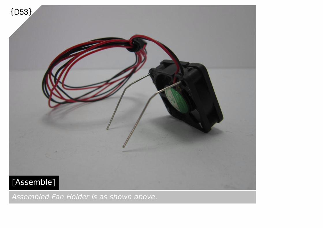
{D53}
[Assemble]
Assembled Fan Holder is as shown above.

{D54}
[Prepare Parts] Parts required for Full Effector assembly.
Assembled
Hot End
= 1 set
Assembled
Fan Holder
= 1 set
Auto Level
Probe Holder
= 1 pc
M3x20mm
Cap Screw
= 2 pcs
M3 Nut
= 4 pcs
M3x16mm
Cap Screw
= 2 pcs

{D55}
[Arrangements] From here onwards, this Build Guide will follow the above arrangements
for X-Y-Z Towers. In essence, X-Y-Z Towers are in counter-clockwise
arrangements, and the one with Extruder Motor will be the Z-Tower.
X -Tower Y -Tower
Z -Tower
X - Y
Y - Z X - Z

{D56}
[Orientate]
Orientate the Assembled Hot End below the Effector as shown
above. Z-Tower is the reference for the above orientation.

{D57}
[Assemble]
Mount the Assembled Hot End into the Effector’s Hot End mount as
shown above. Align the screw holes of the Groove Mount to
Effector’s screw holes.

{D58}
[Assemble]
Mount the Auto Level Probe Holder and thread 2 pcs of M3x20mm
Cap Screws thru the screw holes, and another 2pcs of M3x16mm
Cap Screws thru the Effector screw holes as shown above.
[Tools]
M3 Allen Key M3x20mm Cap Screw = 2 pcs
M3x16mm Cap Screw = 2 pcs
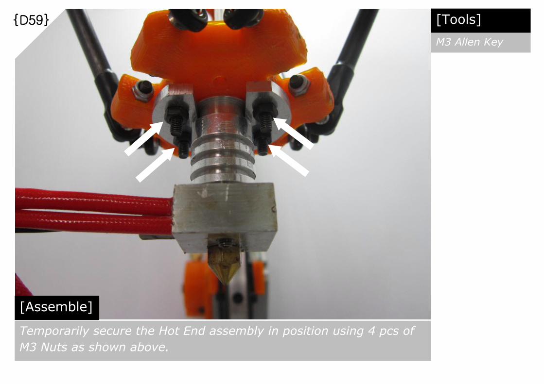
{D59}
[Assemble]
Temporarily secure the Hot End assembly in position using 4 pcs of
M3 Nuts as shown above.
[Tools]
M3 Allen Key
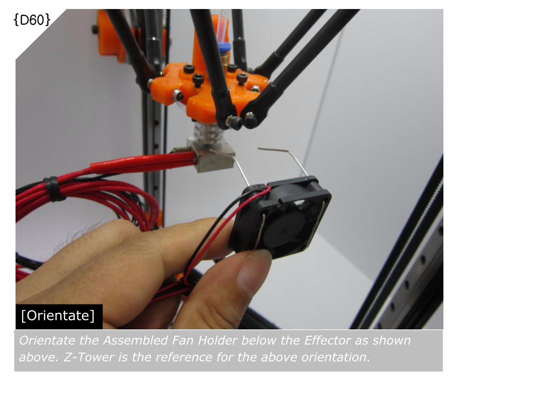
{D60}
[Orientate]
Orientate the Assembled Fan Holder below the Effector as shown
above. Z-Tower is the reference for the above orientation.

{D61}
[Assemble]
Slide the Fan Holder in between the Groove Mount and Effector. Once in position as
shown above, align the Hot End heat block and Fan parallel to the X-Y Edge shown in
Step {D55}. Tighten all the Cap Screws and Nuts and make sure the Hot End
assembly and Fan mount are firmly secured.
[Tools]
M3 Allen Key

{D62}
[Orientate]
Orientate the Fan such that air flows are directed towards the heat sink barrel and the
Aluminum Groove Mount only as shown above. Air flow towards the Heat Block should
be avoided and a safe gap between the Fan and heat block should be maintained.
[Tools]
Long Nose Pliers

{D63}
[Inspection]
Final Fan mount should be centered as shown above.

{D64}
[Prepare Parts] Parts required for Endstop Microswitch assembly.
Endstop Microswitch = 3 pcs
Endstop Wires = 3 pairs

{D65}
[Marking] Mark the same wire housed in socket with Pointer symbol, using eg.
Marker Pen as shown above.
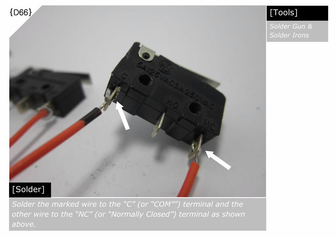
{D66}
[Solder] Solder the marked wire to the “C” (or “COM””) terminal and the
other wire to the “NC” (or “Normally Closed”) terminal as shown
above.
[Tools]
Solder Gun &
Solder Irons

{D67}
[Repeat Steps] Repeat Steps {D65} to {D66}. 3 sets of Endstop Microswitch
assembly needed as shown above.
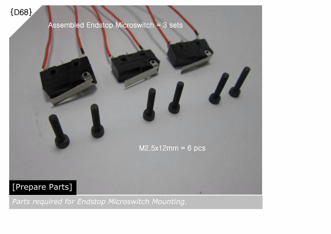
{D68}
[Prepare Parts] Parts required for Endstop Microswitch Mounting.
Assembled Endstop Microswitch = 3 sets
M2.5x12mm = 6 pcs

{D69}
[Assemble]
Fasten the Assembled Endstop Microswitch to the Upper Endstop
Holder by tightening the 2 pcs of M2.5x12mm Cap Screws as shown
above.
[Tools]
M2.5 Allen Key

{D70}
[Repeat Steps & Inspection] Repeat Step {D69} for remaining Endstop Microswitches as shown
above. Make sure Vertical Carriage for all Towers have good contact
with the respective Mircroswith Lever upon hitting the Endstop.

{D71}
[Prepare Parts] Parts required for Auto Level Probe Microswitch assembly.
Endstop Microswitch = 1 pc
Endstop Wires = 1 pair

{D72}
[Solder] Solder the marked wire to the “C” (or “COM””) terminal and the
other wire to the “NO” (or “Normally Opened”) terminal as shown
above.
[Tools]
Solder Gun &
Solder Irons

{D73}
[Preparations] Bend the Microswitch terminals using Long Nose Pliers as shown
above. Trim the Microswitch metal lever to 7mm using Metal Cutter
as shown above.
[Tools]
Long Nose Pliers
& Metal Cutter

{D74}
[Mount] Mount the prepared Auto Level Probe Microswitch to the Auto Level
Probe Holder and tighten the M2.5x12mm Cap Screws as shown
above.
[Tools]
M2.5 Allen Key
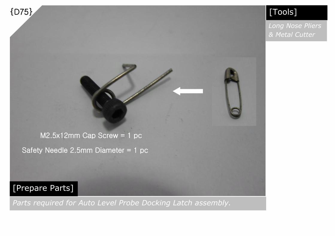
{D75}
[Prepare Parts] Parts required for Auto Level Probe Docking Latch assembly.
M2.5x12mm Cap Screw = 1 pc
Safety Needle 2.5mm Diameter = 1 pc
[Tools]
Long Nose Pliers
& Metal Cutter

{D76}
[Mount] Mount the Auto Level Probe Docking Latch assembly to the Auto
Level Probe Holder as shown above. Gently tighten the M2.5x12mm
Cap Screw just enough to hold the modified Safety Pin in position.
[Tools]
M2.5 Allen Key
7
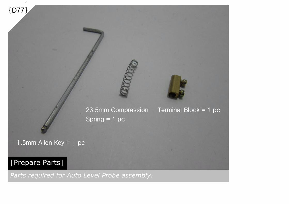
{D77}
[Prepare Parts] Parts required for Auto Level Probe assembly.
1.5mm Allen Key = 1 pc
23.5mm Compression
Spring = 1 pc
Terminal Block = 1 pc
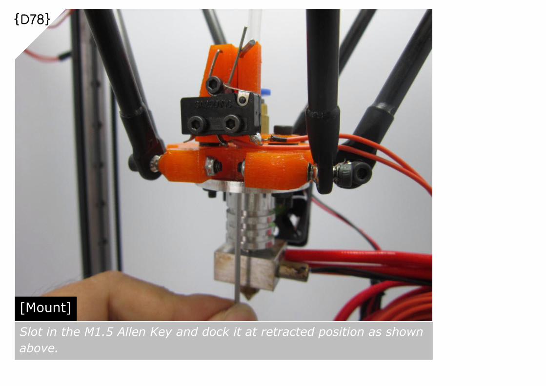
{D78}
[Mount] Slot in the M1.5 Allen Key and dock it at retracted position as shown
above.

{D79}
[Mount] Thread the M1.5 Allen Key thru the 23.5mm Compression Spring then
followed by the Terminal Block. Fully compress the spring and tighten
both screws in Terminal Block as shown above
[Tools]
Screw Driver

{D80}
[Inspections] Left: Auto Level Probe in deployed position. Probe tip must be lower than the
Hot End nozzle tip. Right: Auto Level Probe in Retracted position. Probe tip
must be higher than the Hot End nozzle tip.

{D81}
[Inspection] When Auto Level Probe in Retracted position, Probe tip must be
higher than the Hot End nozzle tip.
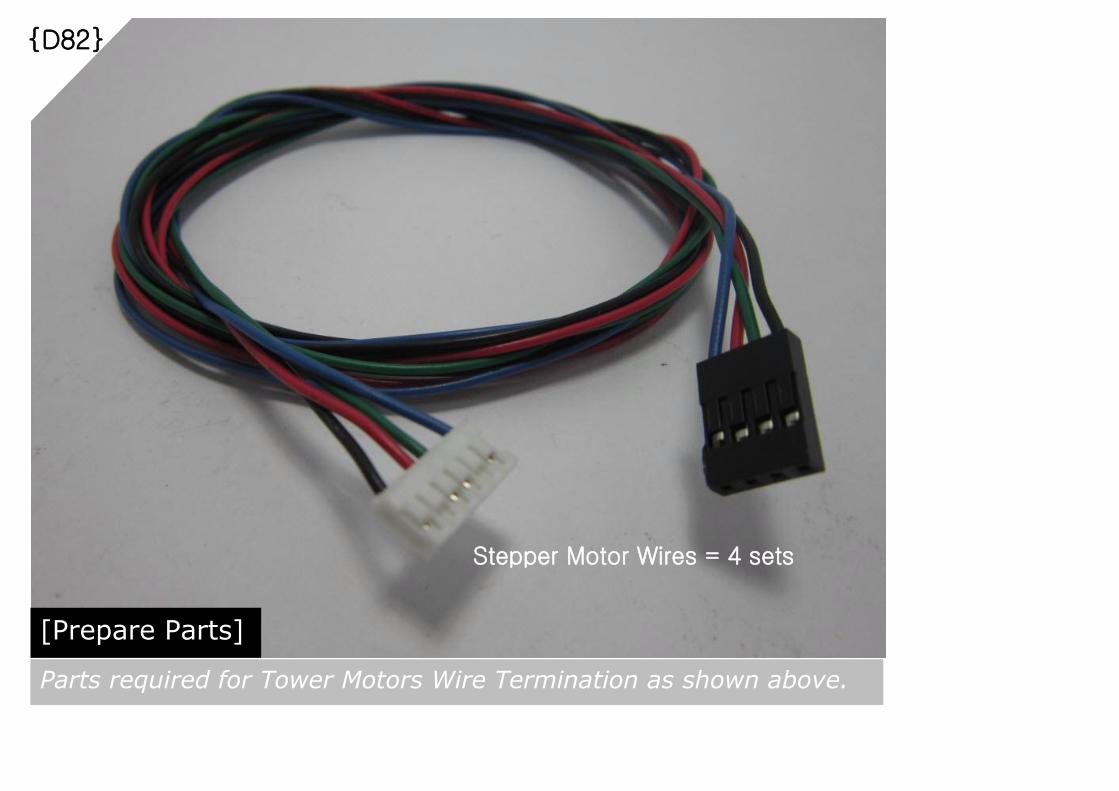
{D82}
[Prepare Parts] Parts required for Tower Motors Wire Termination as shown above.
Stepper Motor Wires = 4 sets
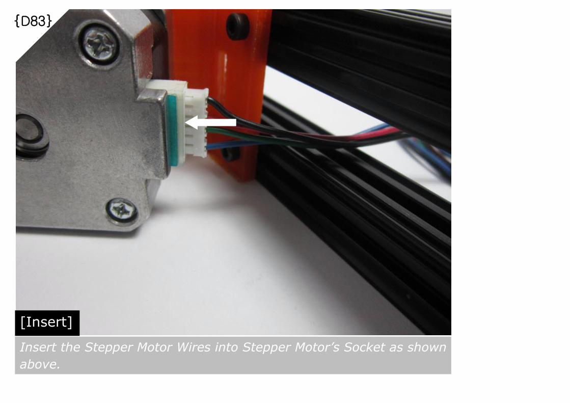
{D83}
[Insert] Insert the Stepper Motor Wires into Stepper Motor’s Socket as shown
above.
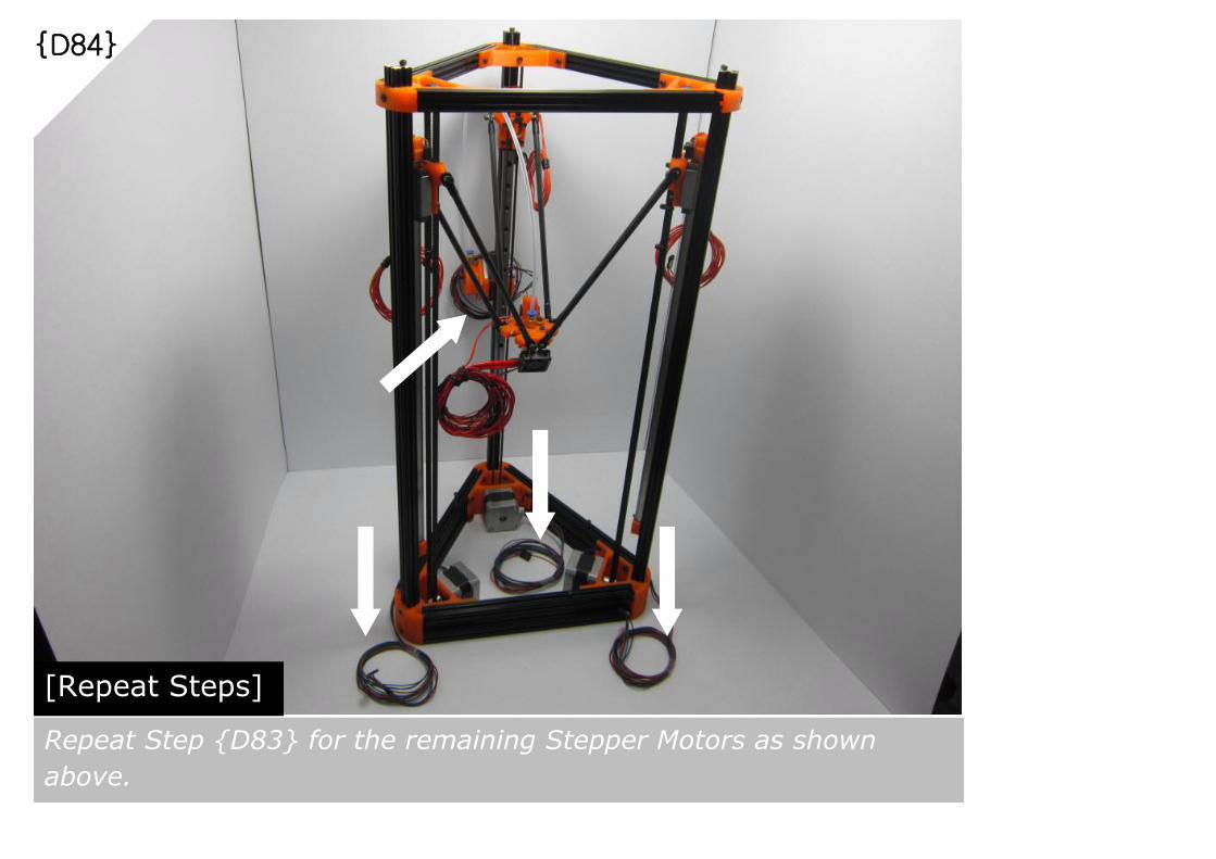
{D84}
[Repeat Steps] Repeat Step {D83} for the remaining Stepper Motors as shown
above.

{D85}
[Prepare Parts] Parts required for Print Bed Mount as shown above.
M3x8mm Cap Screw = 3 pcs
M3 Nut = 6 pcs
180mm Diameter
Glass Bed = 1 pc

{D86}
[Prepare] Apply Kapton Tape or any Heat Resistant Tape on the Glass Bed.
Prepare 3 sets of Glass Bed Fastener using M3x8mm Cap Screws
and M3 Nuts as shown above.
Glass Bed Fastener = 3 sets

{D87}
[Slot In] Slot in the Glass Bed Fastener into the OpenBeam rail guide as
shown above.

{D88}
[Position and Tighten] Lay the Glass Bed on top of the Bottom Frame. Tighten all 3 fasteners once the Glass
Bed is centered properly. Make sure Glass Bed is firmly secured before print.
[Tools]
M3 Allen Key

{D89}
[Prepare Parts] Parts required for Auto Level Probe Retractor as shown above.
M3x20mm Cap Screw = 1 pc
M3 Nut = 2 pcs

{D90}
[Slot In and Tighten] Slot the Auto Level Probe Retractor into the rail guide at X-Z Edge.
Tighten the M3x20mm Cap Screw once in position as shown above.
X-Z Edge
X-Y Edge
Y-Z Edge 80mm
[Tools]
M3 Allen Key
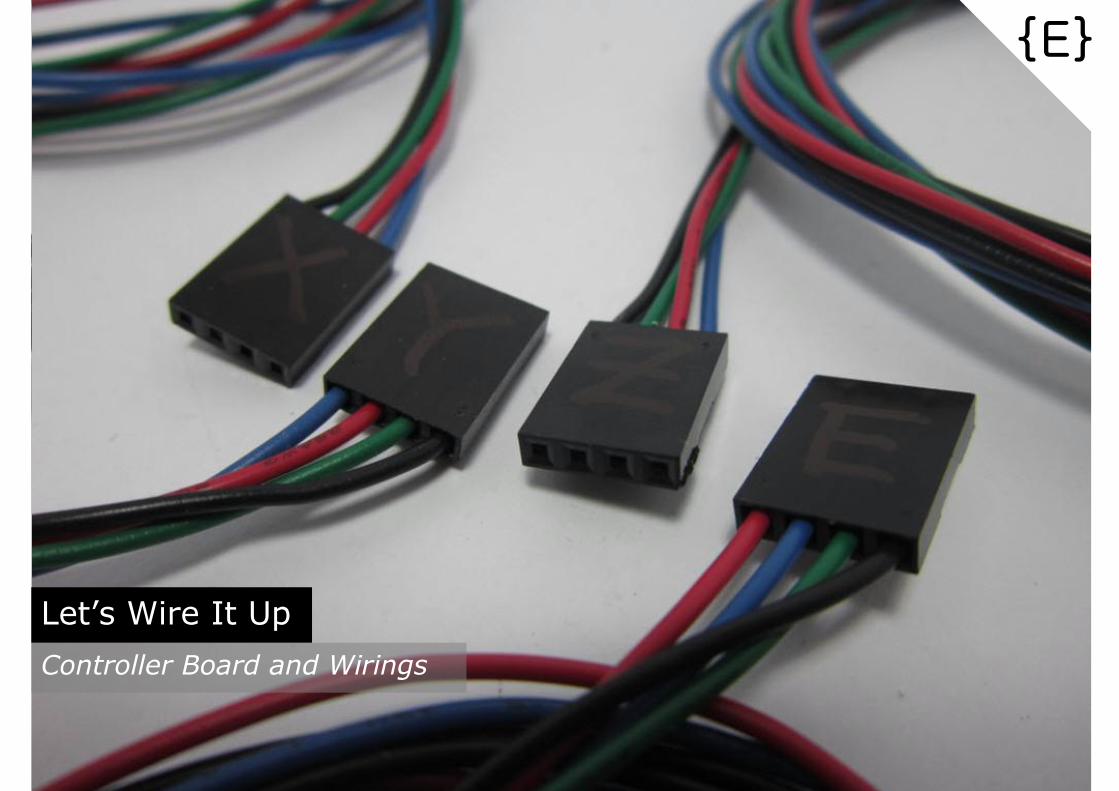
Let’s Wire It Up
Controller Board and Wirings
{E}

{E01}
[Prepare Parts] Parts required for Controller Board Assembly as shown above.
Arduino
Mega2560
= 1 pc
RAMPS 1.4
= 1 pc
Stepper
Driver
= 4 pcs
Jumper
= 12 pcs

{E02}
[Assemble] Fully slot in the RAMP1.4 board on top of the Arduino Mega2560
Controller Board as shown above.

{E03}
[Assemble] Slot in 3 pcs of Jumpers per Stepper Motor slot in RAMPS1.4 board
as shown above. Total 12 pcs of Jumpers needed

{E04}
[Assemble] Slot in 4 pcs of Stepper Driver to RAMPS1.4 board as shown above.

{E05}
[Prepare Parts] Parts required for Controller Board Mounting as shown above.
.
Assembled
Controller Board
= 1 set
M3x35mm Cap Screw = 2 pcs
M3 Nut = 4 pcs

{E06}
[Assemble] Thread M3x35mm Cap Screws thru the boards’ screw holes, then
follow by M3 Nuts as shown above.

{E07}
[Attach] Attach the assembled Controller Board at X-Z Edge of Top Frame
thru the OpenBeam slot guide opening, then tighten the 2 pcs of
M3x35mm Cap Screws as shown above.
[Tools]
M3 Allen Key
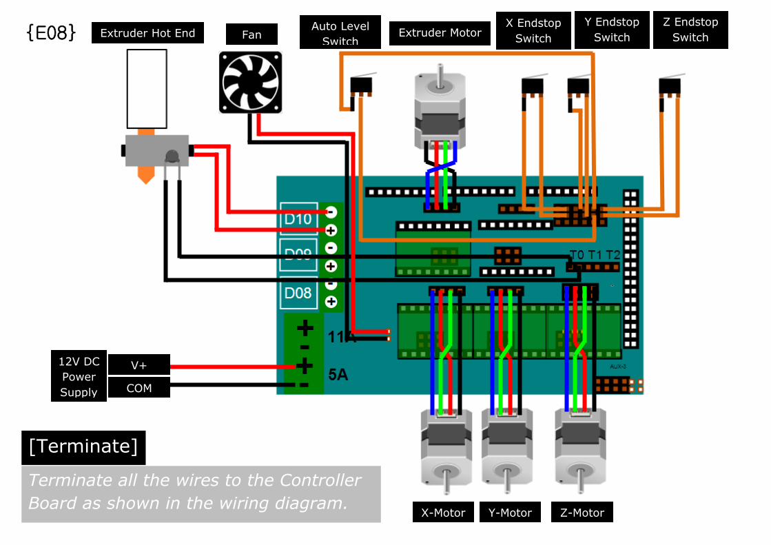
[Terminate]
X-Motor Y-Motor Z-Motor
Extruder Motor
COM
V+
Extruder Hot End Fan Auto Level
Switch
X Endstop
Switch
Y Endstop
Switch
Z Endstop
Switch
Terminate all the wires to the Controller
Board as shown in the wiring diagram.
{E08}
12V DC
Power
Supply

Let’s Power It Up
Power On and Connect to PC
{F}
Note: LCD Controller Board is for illustration purpose only. This Guide will use Computer
Software & USB Connection to operate the Kossel Mini.

{F01}
[Measure] Detach the power terminal from Controller Board and measure the DC Power Supply as
shown above. If terminated correctly, the voltage and polarity should be around +12V
!!!Wrong polarity will cause permanent damage to the Controller Board!!!
[Tools]
Digital
Multimeter
[Caution]
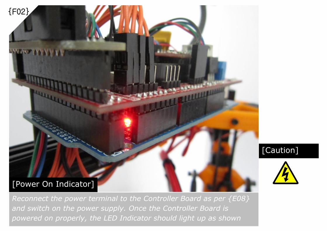
{F02}
[Power On Indicator] Reconnect the power terminal to the Controller Board as per {E08}
and switch on the power supply. Once the Controller Board is
powered on properly, the LED Indicator should light up as shown
above.
[Caution]

{F03}
[Fan Inspection] Make sure FAN is operating ALL THE TIME when Controller Board is powered on.
Also, verify that the FAN airflow is orientated correctly as shown in {D62}.
!!! Continuous cooling is essential to prevent Hotend Jamming or Effector meltdown!!!

{F04}
[Software & Firmware Package] This Guide will use the following Software & Firmware Package for Kossel Mini.
For Windows User [http://www.blomker.com/KosselMini_Windows.zip]
For Mac User [http://www.blomker.com/KosselMini_Mac.zip]
Alternatively, you can check for any latest updates in the future and download them
individually if needed:
Arduino [http://arduino.cc/en/main/software]
Printrun-Pronterface [http://koti.kapsi.fi/~kliment/printrun]
Slic3r [http://slic3r.org/download]
jcrocholl Marlin [https://github.com/jcrocholl/Marlin]
[Latest Updates]
[Download and Extract to Computer] Download the required Software and Firmware Package to the Computer and extract
the .zip file

[Computer]
[Kossel Mini]
[Arduino+RAMPS
Controller]
[Arduino
Software]
[Marlin
Firmware]
[Motors]
[Sensors]
[Hotend]
[Pronterface
Software]
[Slic3r
Software]
[.stl]
[Printed
Item]
[.gcode]
[Marlin
Firmware]
[USB]
[Printing
Material]
{F05}
[.gcode]
[Kossel Mini Firmware and Computer Software Operations Overview] This Guide will use Software and Firmware setup as shown above to
calibrate/fine-tune/operate the Kossel Mini and eventually, first test print.

{F06}
Install Arduino Software in the Computer by executing the .exe file. Once
completed, connect the Computer to Kossel Mini USB port. Verify the COM
Port Number assigned for Arduino Mega 2560 (eg. COM34) as shown above.
[Install and Connect]

{F07}
Run file [Blomker KM File/Marlin_delta2/Marlin_delta2.ino]. Go to Tools-
>Board, select Arduino Mega 2560 as shown above. In case you have been
following exactly our build instructions from Part {A} to {E}, this
Marlin_delta2 Sketch will instantly enable your Kossel Mini for Part {G}
verifications, and then followed by calibration and first test print.
[Open Marlin Firmware Sketch using Arduino Software]

{F08}
Go to Tools->Serial Port, select the COM Port as per assigned in Step {F06}.
[Select the COM Port]

{F09}
Click the “Upload” button to upload the Marlin_delta2 Firmware Sketch to
Kossel Mini Controller Board. Once upload successful, message “Done
Uploading” will be displayed.
[Upload Sketch to Kossel Mini]
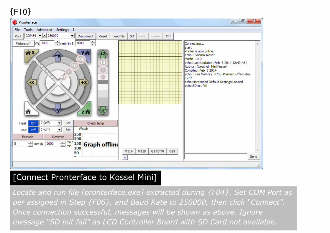
{F10}
Locate and run file [pronterface.exe] extracted during {F04}. Set COM Port as
per assigned in Step {F06}, and Baud Rate to 250000, then click “Connect”.
Once connection successful, messages will be shown as above. Ignore
message “SD init fail” as LCD Controller Board with SD Card not available.
[Connect Pronterface to Kossel Mini]

Let’s Check It Out
Verify Kossel Mini Setup using Pronterface
{G}
Note: Verifications needed to ensure Kossel Mini has no wiring or hardware issues.
Verification result is based on the Marlin_delta2 firmware uploaded to Kossel Mini during {F10}.

{G01}
[Verify Endstops & Auto Level Probe Status]
Carriage in contact with Endstop Switch => ”TRIGGERED”
Carriage NOT in contact with Endstop Switch => ”open”
Auto Level Probe in contact with Switch (Deployed) => “open”
Auto Level Probe NOT in contact with Switch (Retracted) =>”TRIGGERED”
[Observation: x_max, y_max, z_max]
[Observation: z_min]
[MCODE]
M119
[Sample Output]

{G02}
[Verify Nozzle/XYZ Carriages Homing]
[GCODE]
G28
[Observation: Nozzle/XYZ Carriages Movements] All XYZ Carriages will travel towards respective Endstops and slightly back
off after in contact with respective Endstop switch.
[GUI]
[Important Note] Nozzle/Carriage Homing also means to park the Nozzle tip at Cartesian
Coordinate [0,0, MANUAL_Z_HOME_POS]. In this case, [0,0,239]
After Power Cycle or Reset, Controller Board will lost track of Nozzle’s
Cartesian Coordinates/Carriages’ position. It is essential to send GCODE
[G28] or using GUI “HOME” button to update again current Nozzle
coordinates
or

{G03}
[Verify Current Coordinates/Position]
[MCODE]
M114
[Observation: X:0.00Y:0.00Z:239] Indicate the current Cartesian coordinates of Nozzle Tip when HOME.
“Z:239” corresponds to “#define MANUAL_Z_HOME_POS 239” in
[Configuration.h] of Marlin_delta2. This info will be referred during Calibration
stage
[Sample Output]
[Observation: Count X: 425.52Y:425.52Z:425.52] Indicate the current linear position of Carriages on their respective Towers
[Important Note] If output is “X:0.00Y:0.00Z:0.00E:0.00 Count X: 0.00Y:0.00Z:0.00”,
Controller Board have lost track of positions. Need to home all Axis again.

{G04}
[Verify Extruder Motor Extrude and Reverse Motion]
[MCODE]
M302
and
[GUI]
[Observation: Extruder Motor Drive Gear Rotation] After sending MCODE [M302], verify Extruder
Motor Drive Gear Rotation as below:
Extrude => Clockwise Rotation
Reverse => Counter Clockwise Rotation
[Important Note] “#define EXTRUDE_MINTEMP 170” will prevent Extruder Motor from any
motions when Nozzle temperature is below 170C. Hence, MCODE [M302]
needed to enable cold extrusion before this verification is possible
[Extrude]
[Reverse]

{G05}
[Verify Hotend Temperature]
[GUI]
[Observation: Hotend Target Temperature Sustainable] Select 185 (PLA) and click “Set”. Verify that temperature is sustainable (at
least 15mins) after reaching 185C. Then follow by similar verification for
230C. In case failed to attain target temperature after continuous heating:
1. Make sure the FAN airflow not directed to Hotend’s heat block {D62}
2. Make sure Heater and Thermistor wires terminated properly {E08}
[Important Note] Before proceed for Hotend Temperature verification, ensure step {F03}
already verified. At this stage, do not leave the Hotend unattended during
Temperature verifications, especially when heating above 185C. Click “Off”
to cancel heating of Hotend once Temperature verification completed.
[Observation: No Overheating at Effector] Continuous cooling by the FAN airflow should keep the Effector (PLA
material) below 100C.
and
[Caution]
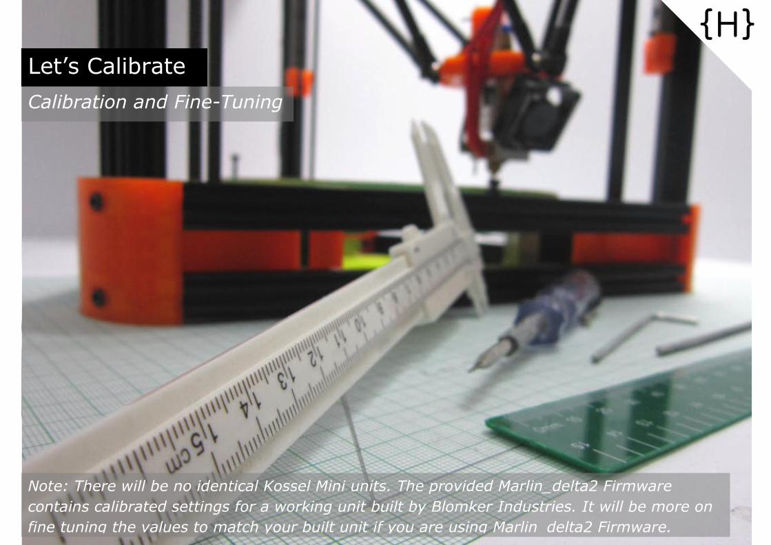
Let’s Calibrate
Calibration and Fine-Tuning
{H}
Note: There will be no identical Kossel Mini units. The provided Marlin_delta2 Firmware
contains calibrated settings for a working unit built by Blomker Industries. It will be more on
fine tuning the values to match your built unit if you are using Marlin_delta2 Firmware.

{H01}
[Differentiate XYZ Towers & XYZ Axes]
To calibrate a Delta Printer like Kossel Mini, it is essential to distinguish XYZ Axes from
XYZ Towers. In essence, Delta Printer makes coordinated movements of XYZ
Carriages on their respective Towers, which will translate to movement of Nozzle
(Print Head) in Cylindrical/Cartesian print space, consist of XYZ Axes and Coordinates.
X-Tower
Y-Tower
Z-Tower
Z-Axis
X-Axis
Y-Axis
Nozzle

Unit of XYZ Coordinates are in [mm].
Boundaries/Radius of the Cartesian print space are specified by Min & Max parameters
of XYZ Axes in [Configuration.h] of Marlin_delta2 Firmware.
Two key Coordinates needed during Calibrations are the HOME Coordinate [0,0,Zmax]
and Center of Bed [0,0,0].
[XYZ Axes and Coordinates]
{H02}
Xmax
Xmin
Ymin
Ymax
Zmax
HOME : [0,0,Zmax]
BED CENTER : [0,0,0]
Nozzle
Zmin
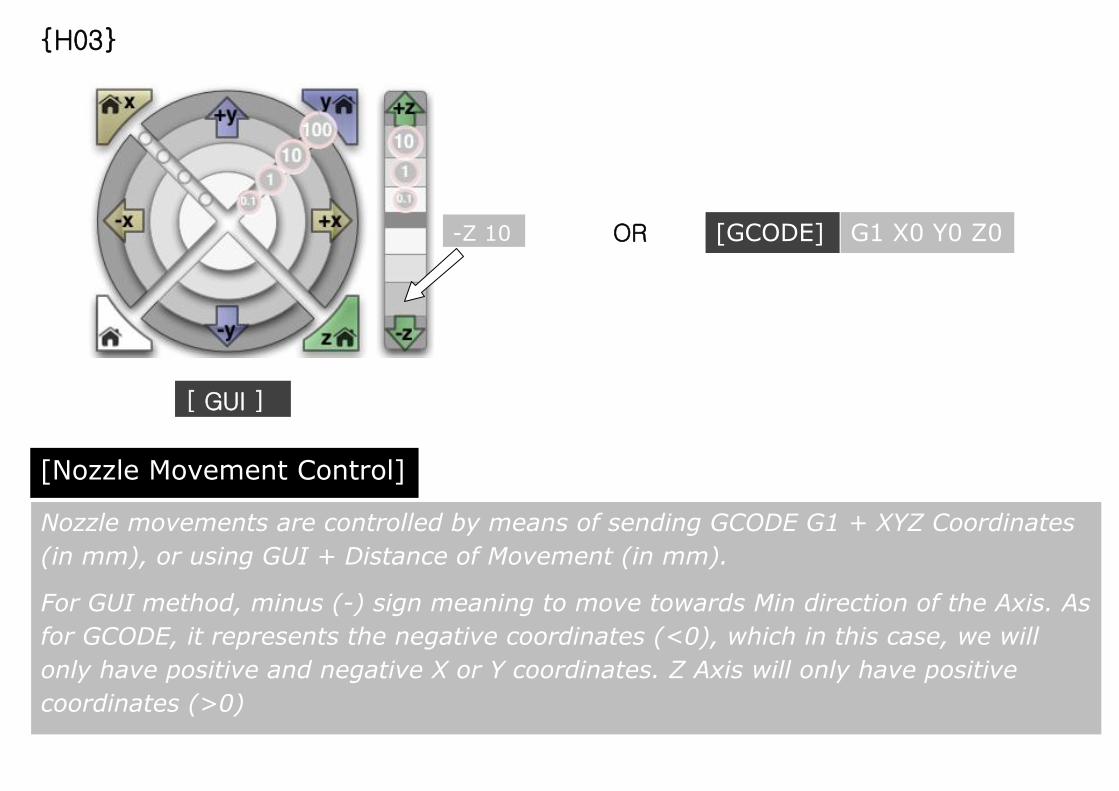
Nozzle movements are controlled by means of sending GCODE G1 + XYZ Coordinates
(in mm), or using GUI + Distance of Movement (in mm).
For GUI method, minus (-) sign meaning to move towards Min direction of the Axis. As
for GCODE, it represents the negative coordinates (<0), which in this case, we will
only have positive and negative X or Y coordinates. Z Axis will only have positive
coordinates (>0)
OR
[ GUI ]
[Nozzle Movement Control]
{H03}
-Z 10 [GCODE]
G1 X0 Y0 Z0

If initial position of Nozzle is at HOME position, illustrations above demonstrate the
difference between movement by GUI + Distance of Movement and GCODE +
Coordinates. Good understanding and combo usage of both methods can help to
shorten calibration time, especially during Z-Axis and Bed Auto Leveling Calibration
{H04}
[Relative vs Absolute Movement]
-Z 10 [GCODE]
G1 Z10
[0,0,229]
[0,0,10]
[Relative Movement] [Absolute Movement]
[0,0,239] [0,0,239]
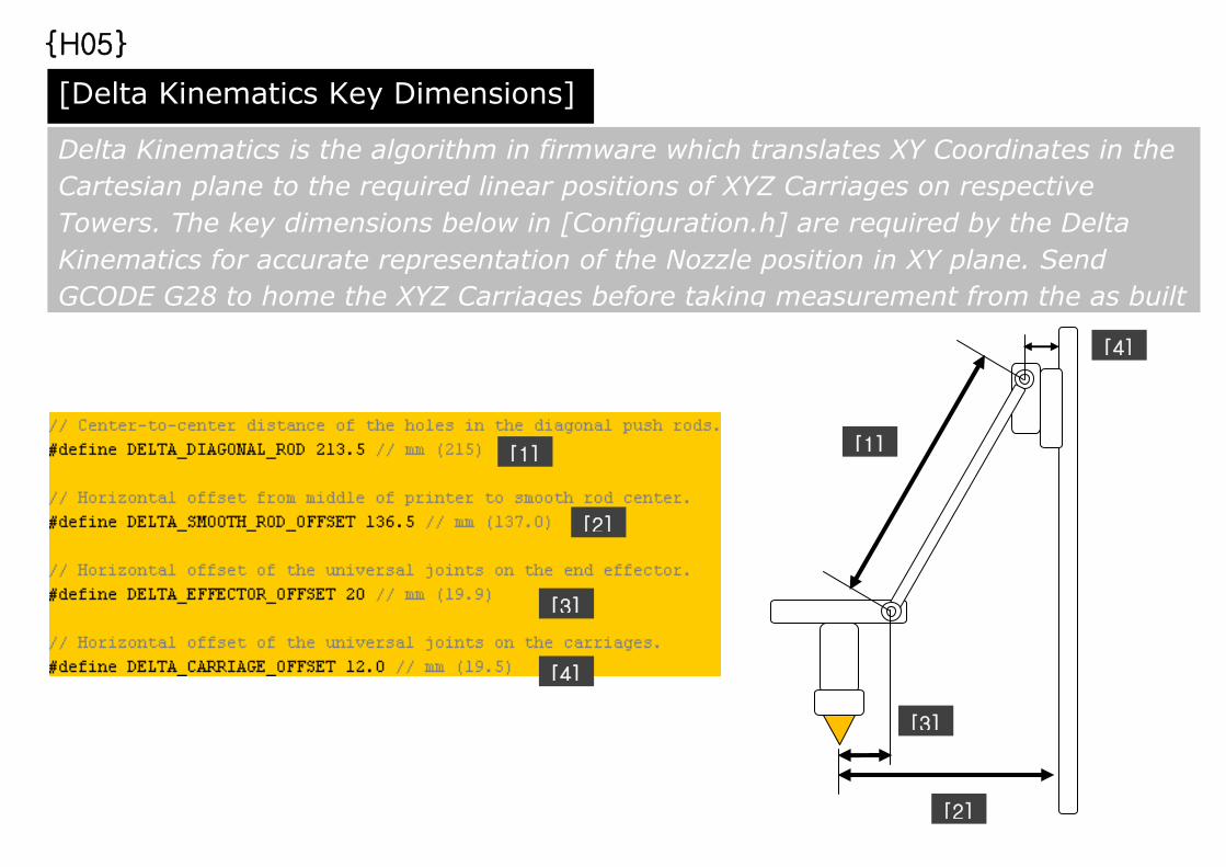
Delta Kinematics is the algorithm in firmware which translates XY Coordinates in the
Cartesian plane to the required linear positions of XYZ Carriages on respective
Towers. The key dimensions below in [Configuration.h] are required by the Delta
Kinematics for accurate representation of the Nozzle position in XY plane. Send
GCODE G28 to home the XYZ Carriages before taking measurement from the as built
unit.
{H05}
[Delta Kinematics Key Dimensions]
[1]
[2]
[3]
[4]
[1]
[2]
[3]
[4]
[1]

Conversions from number of steps to distances travelled in mm are defined in
[Configuration.h] as shown above.
For more info, kindly refer to the wonderful RepRap Calculator tool shared by Josef
Prusa [http://calculator.josefprusa.cz]
Please note that Extruder Motor is using a different Drive Gear than XYZ Motors
{H06}
[XYZ & E Stepper Motor Steps Per mm]
#define DEFAULT_AXIS_STEPS_PER_UNIT {100, 100, 100, 95}
[X] [Y] [Z] [E]

Print Height/Print Bed Centre Calibration procedures using Pronterface are as below:
1. Send GCODE G28 to home the Nozzle
2. Send MCODE M114 to check Z Height at HOME position. Z:239 corresponds to
MANUAL_Z_HOME_POS 239 in [Configuration.h]
3. Send GCODE G1 Z10 to move the Nozzle close to the Print Bed
4. Use GUI to move nozzle 1mm towards Print Bed
5. Repeat 4 till gap between Nozzle and Print Bed less than 1mm
6. Repeat 4 but move 0.1mm towards Print Bed
7. Repeat 6 till Nozzle is 0.1mm above Print Bed. This Nozzle position will be
defined as Print Bed Centre [0,0,0]
8. Send GCODE M114 to check the current Z value.
9. New MANUAL_Z_HOME_POS value = Old MANUAL_Z_HOME_POS value –
current Z value. This new value will defined the Max Print Height.
10. Update #define MANUAL_Z_HOME_POS __?__ with the new value. Then
reupload the updated Marlin_delta2 firmware using step {F09}
11. If 7 is not possible, software Endstop limit reached. Update value in
[Configuration.h] #define min_software_endstops false and repeat Step
{F09}. Kindly disconnect Pronterface before attempting Step {F09}
12. Repeat 1 to 7. Once completed, then Repeat 11 with value true.
[Max Print Height/Print Bed Center Calibration Procedures]
{H07}

GCODE G29 consist a set of continuous procedures which eventually align Nozzle to
move at uniform Z Height above a flat Print Bed.
After sending GCODE G29, 3 procedures as below will be automatically executed:
1. Deploy Z Probe
2. Probe Print Bed (at 37 Locations)
3. Retract Z Probe
Below is the snapshot of G29 main codes found in [Marlin_main.cpp]:
[G29 Bed Auto Leveling]
{H06}
{H08}

The default Z Probe deployment mechanism is by pushing the horizontal portion of Z
Probe against the GT2 belt of Z-Tower. The XYZ coordinates shown below is where
the pushing of Z Probe (in –X direction) against GT2 belt will begin from.
Our recommendation is to deploy the Z Probe manually by hand, then follow by
sending GCODE G28 before sending GCODE G29. This will eliminate the need to
extend the horizontal portion of the Z Probe (using extra materials), and also reduce
the risk of accidental deployment of Z Probe during printing at certain locations.
Manual Z Probe deployment by hand will not affect the Probing and Retraction of Z
Probe in later stage of GCODE G29 procedures.
In case the auto Z Probe deployment method is preferred, make sure the XYZ
coordinates is suitable for your built and horizontal portion of Z Probe is extended.
[G29: Deploy Z Probe]
{H09}
[Important Notes]

By default, the deployed Z Probe will probe the Print Bed at 37 locations. The exact
probe locations are determined by 2 parameters in [Configuration.h]:
This parameter indicates the
Distance between autolevel Z
probing points, and should be
less than print surface radius/3.
In Marlin_delta2 firmware,
value 26 is chosen due to:
1.Print Radius (Xmax, Xmin,
Ymax, Ymin POS) defined is
85mm.
2. Considering that value higher
than 26 might cause collision of
Effector platform/Fan with X & Y
Towers’ GT2 Belt during probing
stage.
{H10}
[G29: Probe Print Bed (at 37 Locations)]
26mm
26mm Xmax Xmin
Ymin
Ymax
[#define AUTOLEVEL_GRID 26]
1st Probe Point:
[26, 78, 0] Print Radius:
85mm
Last Probe Point:
[-26,-78, 0]

This parameter indicates Distance between Nozzle and the deployed Z Probe’s tip. By
placing Z Probe Holder as per {D58}, the X-Offset value is always “0”. The X and Y
Offset values will be used by firmware to direct the Z Probe tip (using GCODE G1) to
the 37 probing locations. As for Z Offset, repeat fine-tuning needed to make sure
Nozzle position at [0,0,0] is the same before and after GCODE G29 procedures.
{H11}
[#define Z_PROBE_OFFSET {0, 14, -6.7, 0}]
Xmax Xmin
Ymin
Ymax
Y Offset: 14mm Z Offset: -6.7mm
Actual GCODE for
1st Probe Point:
G1 X26 Y64
Actual GCODE for
Last Probe Point:
G1 -X26 –Y82
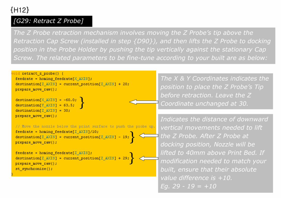
Indicates the distance of downward
vertical movements needed to lift
the Z Probe. After Z Probe at
docking position, Nozzle will be
lifted to 40mm above Print Bed. If
modification needed to match your
built, ensure that their absolute
value difference is +10.
Eg. 29 - 19 = +10
The Z Probe retraction mechanism involves moving the Z Probe’s tip above the
Retraction Cap Screw (installed in step {D90}), and then lifts the Z Probe to docking
position in the Probe Holder by pushing the tip vertically against the stationary Cap
Screw. The related parameters to be fine-tune according to your built are as below:
The X & Y Coordinates indicates the
position to place the Z Probe’s Tip
before retraction. Leave the Z
Coordinate unchanged at 30. }
}
}
{H12}
[G29: Retract Z Probe]

G29 or Auto Bed Leveling Calibration procedures using Pronterface are as below:
1. Deploy Z Probe manually by hand. Send MCODE M119 to verify “Z_min: open”
2. Send GCODE G28 to nullify any position errors introduced by 1.
3. Send GCODE G29 to start the Auto Bed Leveling procedures.
4. Once completed probing at the Last Probing Point (shown in {H10}), Z Probe
retraction procedure will begin by moving to coordinates specified in {H12}
5. In case Z Probe’s tip not position above the Retraction Cap Screw, quickly use
your fingertip as a support to allow lifting of Z Probe to docking position.
6. Once G29 procedures completed (idling), redeploy the Z Probe manually by
hand again.
7. Use Pronterface GUI to move the Z Probe’s tip right above the Cap Screw.
Once in position, send MCODE 114 and record down the X & Y coordinates.
8. Use Pronterface GUI to move Z Probe vertically downward in 1mm steps till the
Z Probe being lifted back into docking position. Send MCODE 114 and record
down the Z coordinate.
9. If needed, updates X and Y coordinates in {H12} as per value obtained in 7.
10. If needed, updates value “19” to New Value1 using equation as follow
New Value1 = 30 - Value obtained in 8
{H13}
[G29 Calibration Procedures]

11. If New Value1 updated in step 10, updates value “29” to New Value2 as follow
New Value2 = New Value1 + 10.
12. If values in 9 to 11 are updated in Marlin_delta2 firmware, reupload the
firmware using step {F10}. Remember to disconnect Pronterface before {F10}
13. Once upload is successful, Controller Board will be reset automatically and the
Print Bed interpolation/offset data stored during last GCODE G29 procedures
will be cleared.
14. Repeat 1 to 13 until Z Probe is retracted properly without user intervention.
15. Send MCODE M114 to verify that Z Coordinate is 40 (40mm above Print Bed)
16. Send GCODE G1 X0 Y0 to center the Nozzle.
17. Use GUI to move Nozzle gradually towards center of Print Bed [0,0,0], same as
the Nozzle position determined during {H06} Step 7.
18. Send MCODE M114 to verify if Z value is zero (“0”). If yes, G29 Calibration
completed.
19. If step 17 is not achievable, or Z Value obtained in step 18 greater than “0”,
reduce the Z Value in [#define Z_PROBE_OFFSET {0, 14, -6.7, 0}, eg, to -6.9,
or vice versa, then follow by reupload of firmware as per step {F10}
20. Repeat 1 to 19 till Nozzle position at [0,0,0] is the same before & after G29
procedures.
[Assemble]
{H14}
[G29 Calibration Procedures Continue]
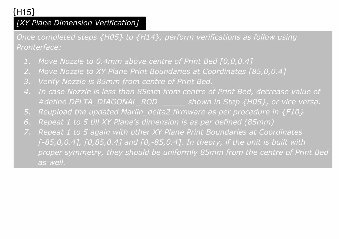
Once completed steps {H05} to {H14}, perform verifications as follow using
Pronterface:
1. Move Nozzle to 0.4mm above centre of Print Bed [0,0,0.4]
2. Move Nozzle to XY Plane Print Boundaries at Coordinates [85,0,0.4]
3. Verify Nozzle is 85mm from centre of Print Bed.
4. In case Nozzle is less than 85mm from centre of Print Bed, decrease value of
#define DELTA_DIAGONAL_ROD _____ shown in Step {H05}, or vice versa.
5. Reupload the updated Marlin_delta2 firmware as per procedure in {F10}
6. Repeat 1 to 5 till XY Plane’s dimension is as per defined (85mm)
7. Repeat 1 to 5 again with other XY Plane Print Boundaries at Coordinates
[-85,0,0.4], [0,85,0.4] and [0,-85,0.4]. In theory, if the unit is built with
proper symmetry, they should be uniformly 85mm from the centre of Print Bed
as well.
{H15}
[XY Plane Dimension Verification]
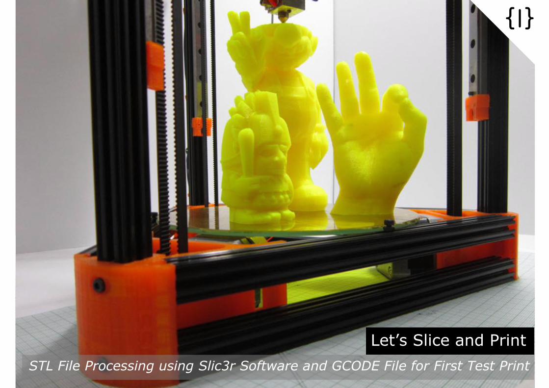
Let’s Slice and Print
STL File Processing using Slic3r Software and GCODE File for First Test Print
Pronterface
{I}

{I01}
Locate and run file [slic3r.exe] extracted during {F04}. In case Blomker KM
Default not loaded as shown above, go to File-> Load Config… and load the
file [Blomker KM Default Slic3r.ini] available in the extracted folder [Blomker
KM Files]. This Config File is only meant to enable first test print for your
Kossel Mini. Further tweaking needed if you have other printing requirements.
[Run Slic3r Software]

{I02}
Locate file [10mm Calibration Cube.STL] in the extracted folder [Blomker KM
Files]. Load the .STL file simply by drag and drop to Slic3r Print Plater.
Dimension and Size info of the object are as shown above. Generate .GCODE
file for test print by clicking “Export G-code” button.
[Load .STL file and Generate .GCODE for First Test Print]
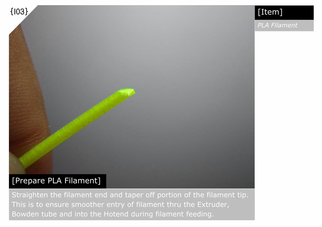
{I03}
[Prepare PLA Filament] Straighten the filament end and taper off portion of the filament tip.
This is to ensure smoother entry of filament thru the Extruder,
Bowden tube and into the Hotend during filament feeding.
[Item]
PLA Filament
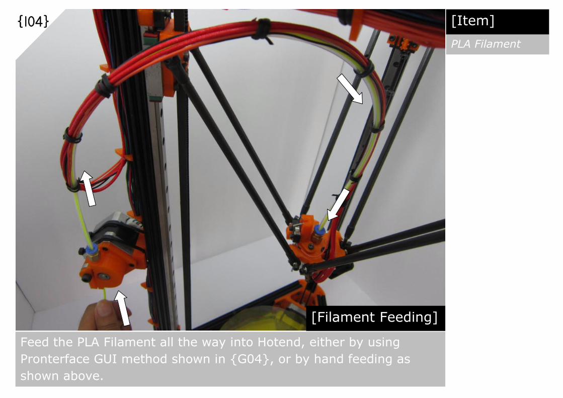
{I04}
[Filament Feeding] Feed the PLA Filament all the way into Hotend, either by using
Pronterface GUI method shown in {G04}, or by hand feeding as
shown above.
[Item]
PLA Filament
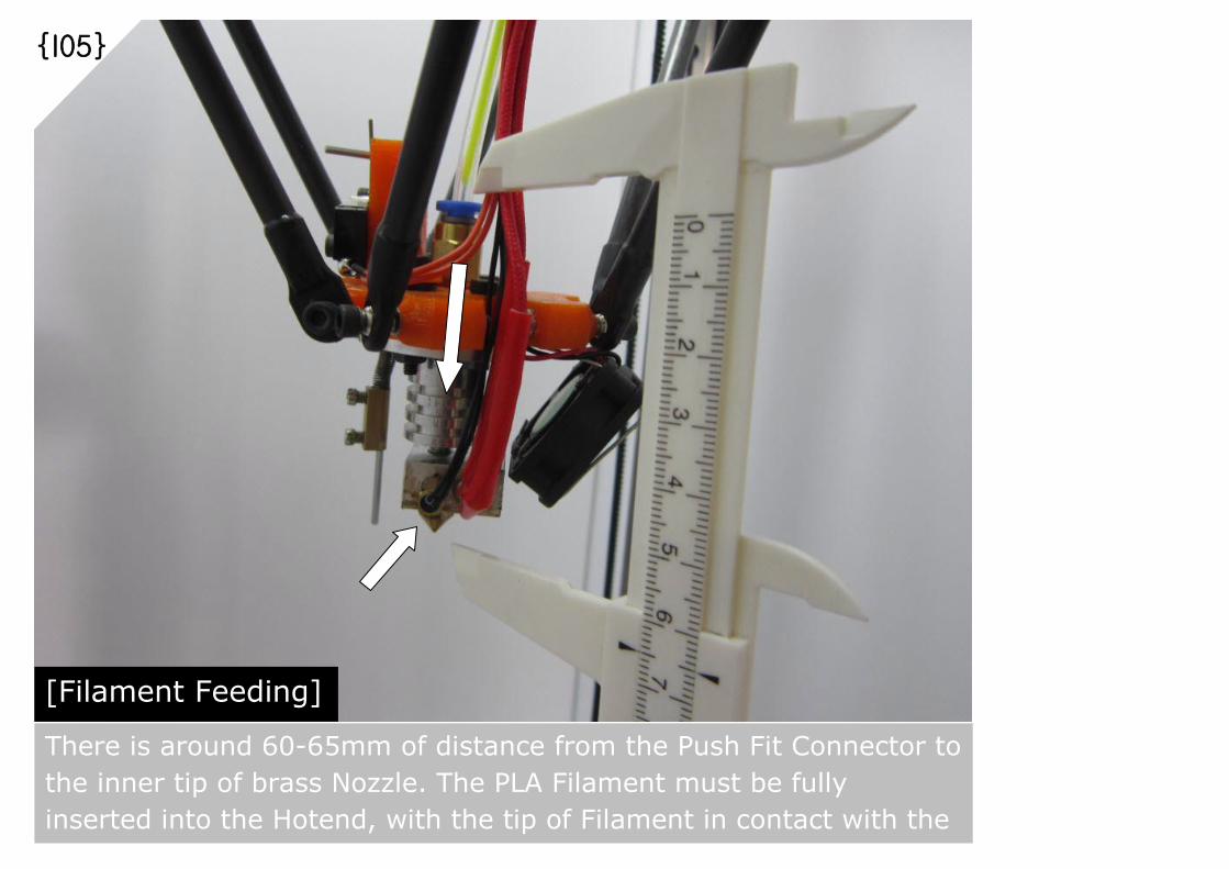
{I05}
[Filament Feeding] There is around 60-65mm of distance from the Push Fit Connector to
the inner tip of brass Nozzle. The PLA Filament must be fully
inserted into the Hotend, with the tip of Filament in contact with the
Nozzle.
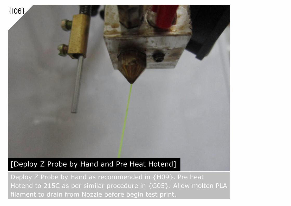
{I06}
[Deploy Z Probe by Hand and Pre Heat Hotend] Deploy Z Probe by Hand as recommended in {H09}. Pre heat
Hotend to 215C as per similar procedure in {G05}. Allow molten PLA
filament to drain from Nozzle before begin test print.
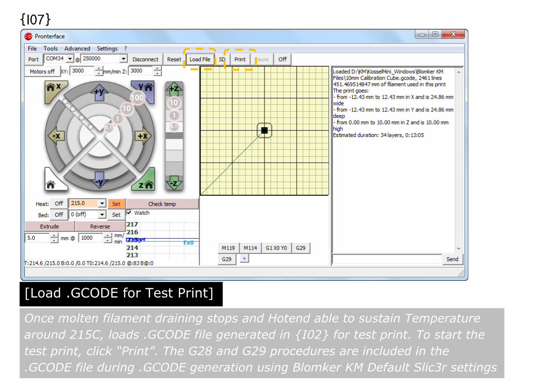
{I07}
Once molten filament draining stops and Hotend able to sustain Temperature
around 215C, loads .GCODE file generated in {I02} for test print. To start the
test print, click “Print”. The G28 and G29 procedures are included in the
.GCODE file during .GCODE generation using Blomker KM Default Slic3r settings
[Load .GCODE for Test Print]

{I08}
[Printing In Progress] 10mm Calibration Cube printing in progress

{I09}
[Measure and Fine Tune] In case dimensions of printed Calibration Cube are not accurate, refer to {H15}
for dimension fine tuning procedures. In case fine-tuning of Steps per mm
needed, it is recommended to recalibrate again from {H05} to {H15}.