Embed Size (px)
Citation preview

KOMMANDER™ — BUILDERCONFIGURATION GUIDE FOR RED ALERT™
KMN-BUILD-A
KMN-BUILD-A

1 REVISIONDescription Author Revision Date
First publication Stéphanie Legros 1.0 January 31, 2019Translation to English 1.1 May 31, 2019
New features (SVG, keyboardcommands, etc.)
Stéphanie Legros 1.2 September 11, 2019
New features (groups, helpdialogs)
Stéphanie Legros 1.3 November 6, 2019
1© All rights reserved for Cyberkar® Systems. 2020

2 COPYRIGHT© Cyberkar® Systems, 2020
No part of the documentation materials accompanying this Cyberkar® Systems software product may bereproduced, transmitted, transcribed, stored in a retrieval system, sold, exploited commercially ortranslated into any language or computer language, in any form or by any means, including, but notlimited to, electronic, magnetic, optical, chemical, manual, or otherwise without prior written permissionof Cyberkar® Systems.
The contents of this documentation are protected by applicable copyright laws and will be distributedwith a software that includes an end user license agreement.
The information contained herein is provided for informational purposes only and is subject to changewithout notice. Cyberkar® Systems assumes no responsibility or liability for any errors or inaccuraciesthat may appear in the informational content contained in this document.
Cyberkar® Systems, Cyberkar® and Kommander™ logos are trademarks of Cyberkar® Systems in theUnited States and Canada. Other trademarks used in this document may be trademarks of themanufacturers or vendors of the respective products.
Cyberkar® Systems
3026 rue Anderson, suite 202
Terrebonne, Québec, Canada
J6Y 1W1
Phone: 450-951-3080
Fax: 450-823-0192
http://www.cyberkar.com
2© All rights reserved for Cyberkar® Systems. 2020

3 CONTENTS1 Revision................................................................................................................................................1
2 Copyright..............................................................................................................................................2
3 Contents...............................................................................................................................................3
4 Description...........................................................................................................................................6
5 Steps.....................................................................................................................................................7
5.1 Plan...............................................................................................................................................7
5.2 Create...........................................................................................................................................8
5.3 Test...............................................................................................................................................8
5.4 Document.....................................................................................................................................9
5.5 Deploy..........................................................................................................................................9
6 Login...................................................................................................................................................10
7 General...............................................................................................................................................10
7.1 File menu....................................................................................................................................10
7.1.1 New....................................................................................................................................11
7.1.2 Open...................................................................................................................................12
7.1.3 Open Red Alert (Config.vmod)............................................................................................12
7.1.4 Download...........................................................................................................................12
7.1.5 Create documentation........................................................................................................13
7.1.6 Delete.................................................................................................................................13
7.1.7 Rename...............................................................................................................................13
7.1.8 Quit.....................................................................................................................................13
7.1.9 About..................................................................................................................................14
7.1.10 Preferences.........................................................................................................................14
7.2 Save............................................................................................................................................15
7.3 Red Alert Local/Remote..............................................................................................................15
7.4 Validate......................................................................................................................................15
7.5 Notification.................................................................................................................................16
8 Tabs....................................................................................................................................................16
8.1 Info.............................................................................................................................................16
3© All rights reserved for Cyberkar® Systems. 2020

8.2 Pages..........................................................................................................................................16
8.2.1 General...............................................................................................................................17
8.2.2 Navigation...........................................................................................................................18
8.2.3 Page setup..........................................................................................................................19
8.2.4 Groups................................................................................................................................21
8.2.5 Items...................................................................................................................................24
8.2.6 Templates...........................................................................................................................31
8.2.7 Figure..................................................................................................................................31
8.3 Applications................................................................................................................................32
8.3.1 Application Search..............................................................................................................33
8.3.2 Calibration..........................................................................................................................34
8.3.3 Notepad..............................................................................................................................34
8.3.4 Red Border..........................................................................................................................34
8.4 Commands..................................................................................................................................36
8.4.1 Page....................................................................................................................................36
8.4.2 Application..........................................................................................................................39
8.4.3 Browser..............................................................................................................................41
8.4.4 System................................................................................................................................42
8.4.5 Volume...............................................................................................................................44
8.5 Timers.........................................................................................................................................46
8.6 Monitors.....................................................................................................................................46
8.6.1 Monitors.............................................................................................................................46
8.6.2 Reactor...............................................................................................................................58
8.6.3 Conditions...........................................................................................................................59
8.6.4 Commands..........................................................................................................................61
8.7 NetMotion® Monitors................................................................................................................73
8.8 Ports management.....................................................................................................................73
8.8.1 Config Validation.................................................................................................................73
8.8.2 CAN Port.............................................................................................................................73
8.8.3 Property..............................................................................................................................74
8.8.4 UDP Port.............................................................................................................................74
8.8.5 Serial port...........................................................................................................................75
4© All rights reserved for Cyberkar® Systems. 2020

8.8.6 NetMotion®........................................................................................................................75
9 Step-by-step guide.............................................................................................................................76
9.1 Customize the Fixed page...........................................................................................................76
10 Technical Assistance.......................................................................................................................77
5© All rights reserved for Cyberkar® Systems. 2020
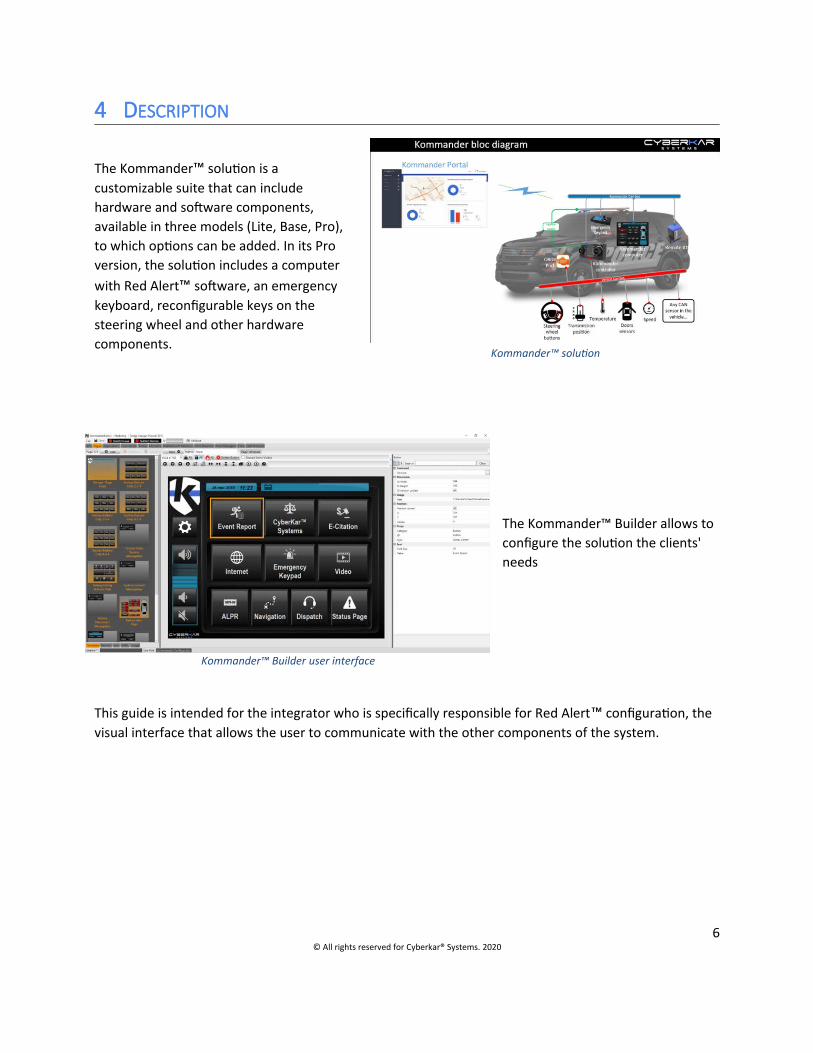
Kommander™ solution
Kommander™ Builder user interface
4 DESCRIPTION
The Kommander™ solution is acustomizable suite that can includehardware and software components,available in three models (Lite, Base, Pro),to which options can be added. In its Proversion, the solution includes a computerwith Red Alert™ software, an emergencykeyboard, reconfigurable keys on thesteering wheel and other hardwarecomponents.
The Kommander™ Builder allows to configure the solution the clients' needs
This guide is intended for the integrator who is specifically responsible for Red Alert™ configuration, the visual interface that allows the user to communicate with the other components of the system.
6© All rights reserved for Cyberkar® Systems. 2020

5 STEPS
5.1 PlanEven before opening the Kommander™ Builder, the configurator has the information to do its job, to know what the client wants to get out of Red Alert™.
These few facts can guide the person who will identify the clients’ needs in developing the match plan:
Does the client want to present their logo in the interface? Can the client supply it?
What applications does the client want to be able to open? What are the paths associated with the applications?
Which websites does the clientwant to access? Which are theassociated URLs?
Does the client want to view a PDFfile? What is the link to thisfolder?
Does the client want a page onrevolving lights?
With the collection of this information, amodel presenting the main pages of theconfiguration can be designed andpresented to the client for approval.
Key Function Parameters1 Notepad Open the Notepad App C:\Windows\System32\Notepad.exe2
Google Maps
Open a browser tab in the Google
Maps site (tab shown again by
pressing again)
https://www.google.com/maps
3Documentation Open the PDF folder C:\Mes_apps\Documents
…
7© All rights reserved for Cyberkar® Systems. 2020
Red Alert™ Layout template

Global configuration mockups forKommander™ solution are available forsupported vehicles. For more details, askyour trainer.
5.2 Create
The tools offered by the Red Alert™ configurator allow you to create a multitude of pages to meet the needs of the client. All graphic and functional possibilities are detailed in the Tabs section.
If the configuration requires advanced controls (e.g., activation of revolving lights or sirens), contact an integrated certified Controller Configurator to process this part of the configuration.
5.3 Test
Before deployment, we recommend testing the configuration in two steps:
with the Kommander™ Builder validation tools (Validation, Red Alert Local and Remote keys) integrated with other system components, in the target environment, with or without
Explorer.
8© All rights reserved for Cyberkar® Systems. 2020
Mockup examples
5.4 Document
Creating documentation for the user is recommended.
See Documentation.
Similarly, we suggest that the configurator to note, on the Info tab, the changes made to the client’s configuration over time, to facilitate tracking.
5.5 Deploy
The configuration is deployed from the portal. For more details, see the User Guide Portal (coming soon).
9© All rights reserved for Cyberkar® Systems. 2020
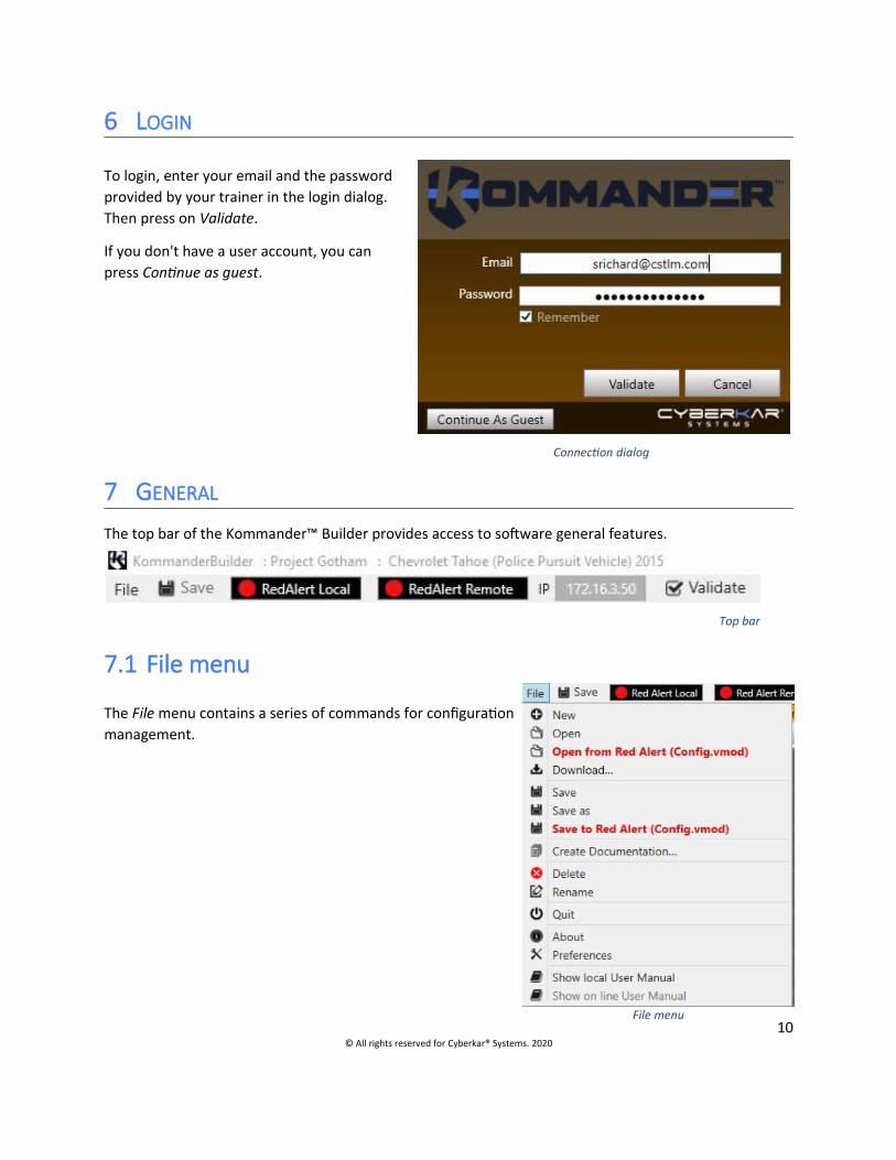
Connection dialog
Top bar
File menu
6 LOGIN
To login, enter your email and the passwordprovided by your trainer in the login dialog.Then press on Validate.
If you don't have a user account, you canpress Continue as guest.
7 GENERAL
The top bar of the Kommander™ Builder provides access to software general features.
7.1 File menu
The File menu contains a series of commands for configurationmanagement.
10© All rights reserved for Cyberkar® Systems. 2020

7.1.1 New
The New command helps the user to create a new configuration and offers to read this user manual, to select a configuration template (see Download... section) or create a new configuration from scratch.
When you opt to create a new configuration, adialogue proposes to name the configuration andto choose the type of vehicle concerned. Note thatit is important to make sure to choose the correctvehicle year, as this may affect the properoperation of the configuration.
11© All rights reserved for Cyberkar® Systems. 2020
Create a new configuration dialog
New configuration dialog

Document Download dialog
7.1.2 Open
The Open command opens an already existingconfiguration. A selector shows theconfigurations created or downloaded to thestation.
7.1.3 Open Red Alert (Config.vmod)
The Red Alert Open (Config.vmod) command opens the current Red Alert™ configuration. Some aspects of the configuration can then be reviewed and revised to meet the client's needs.
7.1.4 Download...
Examples of configurations and templatesare available in the File menu, sub-menu Download...
The configurator can start a newconfiguration using sample configurations,which is recommended, or use them tocreate an original configuration.
Downloadable page templates are goodstarting points for creating ergonomic andaesthetic interfaces.
12© All rights reserved for Cyberkar® Systems. 2020
Configuratiom Selector dialog

Delete Configuration dialog
Rename Configuration dialog
7.1.5 Create documentation...
The Create Documentation… command is used to generate a .docx document associated with the configuration. This document provides an overview of the current configuration.
7.1.6 Delete
The Delete command is used to delete aconfiguration. A selector shows thesettings so that the user can select theone to delete.
7.1.7 Rename
The Rename command is used torename a configuration.
7.1.8 Quit
The Quit command allows you to log out of the application after a work session.
13© All rights reserved for Cyberkar® Systems. 2020

7.1.9 About
The About command allows you to viewthe current version of our configuratorand check if updates are available withthe Check New Version button… Readthe release notes with Notes... button.
The Download Red Alert… button offersto download the latest version of RedAlert™.
To contact Cyberkar® support team,press the Write to Cyberkar®... button.
The End User License Agreement isdisplayed.
7.1.10 Preferences
The Preferences command allows you to adjust several interface components:
the application interface language(French/English);
the display of explanatory tooltips whenhovering over certain fields
spacing, in pixels, the virtual grid used whencreating the pages, to facilitate alignment;
the position of Red Alert™ Local (usefulespecially in the presence of several screens);
the creation of placeholder when an element is deleted.
14© All rights reserved for Cyberkar® Systems. 2020
About dialog
Tooltip
Preferences dialog

7.2 Save
The new configuration can be saved from the Save button or from the Filemenu (saving to the current location or another location). Note that a configuration with validation errors can be saved; however, it cannot be deployed in Red Alert™ Local or Remote.
7.3 Red Alert Local/Remote
The Red Alert Local and Red Alert Remote buttons allow you to view the configuration created in Red Alert™ locally or remotely on another computer whose IP address will be specified in the field adjacent to the Red Alert Remote button.
If Red Alert™ is started locally, its position in the screen can be adjusted from the preferences.
7.4 Validate
The Validate button verifies the integrity ofthe configuration by ensuring that allcredentials are unique. If this is not the case, areport is displayed showing the points to becorrected in order to have a validconfiguration.
7.5 Notification
An indication appears in the upper-right corner when anew version of Kommander™ Builder is available. Seerelease notes with Info... button. Take advantage of newfeatures as soon as possible!
15© All rights reserved for Cyberkar® Systems. 2020
Validation dialog
New Version Available Dialog

Info tab view
Page tab view
8 TABS
8.1 Info
Configuration information isavailable in the Info tab.
1. Type of vehicle2. Date created3. Date of modification4. Description5. Modification notes
The Add Separator and Add Date buttons allow you to sequencechanges made in the configuration.
8.2 Pages
Red Alert™ UI elements can beconfigured in Kommander™ Builder.The visual elements (keys, text, images)of the pages can be adapted accordingto the needs of the client.
16© All rights reserved for Cyberkar® Systems. 2020

Restart request modal dialog
8.2.1 General
The Red Alert™ pages correspond to what will be seen on the vehicle screen. Red Alert™ allows regular pages or modal dialogues to be displayed. The elements of the Fixed page are superimposed on regular pages.
8.2.1.1 Fixed Page
The Fixed page allows to set the elements to be reproduced onall regular pages (e.g. date, logo, time, etc.).
A check box allows to choose whether Fixed page elements willbe reproduced on regular pages for editing.
8.2.1.2 Regular page
Regular pages usually have a series of interface elements to perform commands.
8.2.1.3 Modal dialog
Modal dialogs usually present a question tothe user, who then has to choose betweentwo options, either to proceed with theaction (e.g. restart the system) or to cancelit (then return to the previous page with theShowPage command with the Backparameter). They are displayed in thecentre of the screen, above the previouspage.
The ID of a modal dialogue must startwith messagebox for it to be displayed in this (centred) format.
8.2.2 Navigation
The navigation bar allows you to add, remove and navigate between pages. It also offers template management.
17© All rights reserved for Cyberkar® Systems. 2020
Fixed page view

Page Navigation Status
Add page to configuration
Delete configuration page
Go to the previous page
Go to the next page
A unique name assigned to a regular page or a modal dialog page; by default, they are numbered (e.g. 1, 2, 3…)
Menu to save ordelete pagetemplates.
8.2.2.1 Add a new page
To add a new page, choose its name and its type in thedialog:
Full Screen Page: regular page
Information Dialog: modal window to informthe user (e. g. low battery)
Confirmation Dialog: modal window to informthe user before a command execution (e. g.restart computer)
Text input Dialog: modal window to enter text(e. g. tet to send to a third party)
Password input: modal window to enter apassword
18© All rights reserved for Cyberkar® Systems. 2020
Page Template Menu
Add new page dialog

Layout bar
8.2.3 Page setup
Layout is facilitated by features that allow you to move between selections, move items, lock items, and highlight or background items.
Adjust the resolution of thescreen targeted by theconfiguration
Unlock page items (position and size)
Lock page items (position and size)
Delete all the items on the page
Delete the selected item
Show/hide Fixed page items
Move left
Move right
Move up
Move down
Move upwards of one level (in case of superimposed items)
Move down of one level (in case of overlapping items)
Expand item
Reduce item width
19© All rights reserved for Cyberkar® Systems. 2020
Increase item height
Decrease item height
Duplicate item
Select previous item
Select next item
Access Button Behaviour dialog
Access Help (shortcuts)
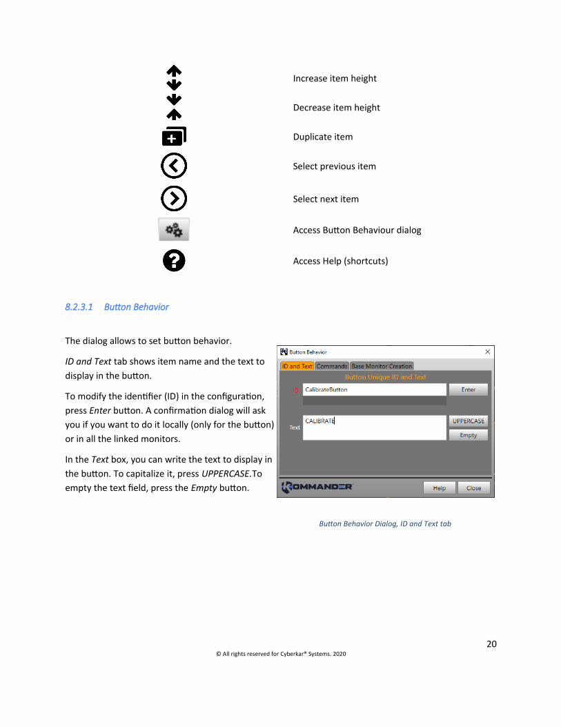
8.2.3.1 Button Behavior
The dialog allows to set button behavior.
ID and Text tab shows item name and the text todisplay in the button.
To modify the identifier (ID) in the configuration,press Enter button. A confirmation dialog will askyou if you want to do it locally (only for the button)or in all the linked monitors.
In the Text box, you can write the text to display inthe button. To capitalize it, press UPPERCASE.Toempty the text field, press the Empty button.
20© All rights reserved for Cyberkar® Systems. 2020
Button Behavior Dialog, ID and Text tab

In the Commands tab, double-click on a commandor select it and press Add Command to associatethe command to your button. You can also removethe command by double-click or with the RemoveCommand button.
The Base Monitor Creation tab allows to createadvanced controls, as an application buttonmanaged by the VPN status.
8.2.4 Groups
The feature groups allow user to create visual elements andall necessary resources to do their job in Red AlertTM. Wherenecessary, user can choose interface language in a dialog.
21© All rights reserved for Cyberkar® Systems. 2020
Choice of language dialog
Button Behavior Dialog, Base Monitor Creation tab
Button Behavior Dialog, Commands tab

8.2.4.1 Volume control
The volume control group allows to add regular buttons for increase and decrease thecomputer’s main volume, toggle button to switch between mute mode activation anddeactivation, and a volume meter to represent volume state. A volume monitor makesthese components functional, and each click on a button is accompanied by an audiblealert.
8.2.4.2 CRPQ Launcher
The CRPQ Launcher group allows to add a toggle button to show CRPQapplication. A dialog helps to fill the application parameters. Anapplication monitor represents the state of the application: the buttonis pushed down when the application is started.
8.2.4.3 Files Browser
The Files Browser group allows to add a button to go to a file dialog(PDF, PNG and JPEG) and then display the documents in the RedAlert™ browser. The monitor linked make these componentsfunctional. Only one files browser can be added in a configuration.
22© All rights reserved for Cyberkar® Systems. 2020
Volumecontrol group
CRPQ Button
Button for File Dialog
Dialog to fill CRPQ application parameters

It will open a dialog to choosebutton’s text, add/deletedirectories (folders) and assign aname (category) to them. UseJPEG and PNG checkboxes toshow or hide images in thebrowser.
8.2.4.4 WEB Browser
The WEB Browser group allows to add a button to go a Web pagein Red Alert™ browser. The commands and monitors linked makethese components functional.
It will open a dialog to choosebutton’s text, the URL (webpage) and give a name to thebrowser tab.
23© All rights reserved for Cyberkar® Systems. 2020
Button for Web Browser
Dialog to add an URL
PDF and images browser

8.2.4.5 Settings page
The Settings page group allows to add the buttons tomanage Cyberkar® screen brightness (day brightness,night brightness, increase and decrease brightness),to calibrate Cyberkar® screen, to log off, to shut downthe computer and to restart it. The commands andmonitors linked make these components functional.
8.2.4.6 VPN
The Mult-IP VPN Connect Status and NetMotion™ VPNConnect Status allow to display connection status(Connected/Disconnected) in a text on a page followingthe VPN in the system (Mult-IP or NetMotion™). TheVPN are mutually exclusive. The text to display can beset in the dialog.
8.2.5 Items
8.2.5.1 Properties
Items share some general properties and aredistinguished by specific properties. Theconfigurator will adjust the properties as needed.
A properties editor is used to adjust the values.Descriptions of the general properties are set outbelow; the specific properties are presented in theelement-specific sections.
24© All rights reserved for Cyberkar® Systems. 2020
Settings page group
Dialog to choose connection status terms
Properties editor
General properties
ID: A unique name assigned to an item, which will be used as a reference throughout the configurator. Recommendations: Name your interface items with meaningful names (e.g. dates, car, Police).
X, Y: Position of the item on the screen, relative to the upper left corner.
A) Width, B) Height: Item size.
Group ID: if applicable, group from which the item was created
Description: short free-text for documentation
Path: For images, path to the image (.png or .xaml), normally in the Media folder. Note Images must also be added to Red Alert™ itself.
Zindex: Item overlay order. (e.g., an item with a zindex of 50 will be above a zindex item of 10).
8.2.5.2 Graphic
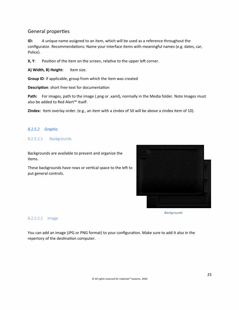
8.2.5.2.1 Backgrounds
Backgrounds are available to present and organize theitems.
These backgrounds have rows or vertical space to the left toput general controls.
8.2.5.2.2 Image
You can add an image (JPG or PNG format) to your configuration. Make sure to add it also in the repertory of the destination computer.
25© All rights reserved for Cyberkar® Systems. 2020
Backgrounds

Volume Meter element
Rectangle element
Button element
8.2.5.2.3 Volume Meter
The volume indicator provides a visual indication of the system volume.
Specific properties
Value: default value (e.g. 50)
8.2.5.2.4 Rectangle
The rectangle allows you to visually frame other items (buttons,text, etc.). The colour and opacity of the rectangle can beadjusted to achieve the desired aesthetic appearance.
8.2.5.3 Button
Several types of buttons can be used in Red Alert™: regularbutton, toggle button, repeat button, round button, and imagebutton.
Specific properties
On Click: A command from the Commands tab can be linked directly to the button; if the command is more complex, a monitor must be added with a message of type OnGUIELEMENTNAME_Click .
Focus Tab Index: determines, for buttons that can take the focus (Focusable), the navigation order
Focusable: determines if the button can focus
Background: Button colour; this property is only available if the Flex style is chosen.
Foreground: Button text and icon colour; this property is only available if Flex style is chosen.
Highlight: The colour of the sidebar displayed when a button is pressed, or, for a toggle button, when it ispressed; this property is only available if the Flex style is chosen.
26© All rights reserved for Cyberkar® Systems. 2020

Repeat button element
Luminosity: Button brightness (levels 0 to 100). By default, the brightness is 20. This property is only available if the Flex style is chosen.
Shape: Button shape (CaretHex, CaretLeft, CaretRight, Round, Star, Rectangle); shape is only available if Flex style is chosen.
Style: Button style (Text [for regular button only], Center, Red_Center, Glossy_Center, Flex). The Flex style must be chosen to modulate Shape, Background, Foreground, Highlight and Luminosity properties.
Automatic Text Wrap: determines if, when a line of text is full, the excess text will be rolled back to the next line
Font Size: Font size used in the button
Value: text to add to button
8.2.5.3.1 Toggle Button
The toggle button has the peculiarity of having a pressed state and anon pressed state. It therefore represents the status of certainbinary features (e.g. emergency light on, application started, mutemode on, etc.). Status can be monitored using a CheckedChanged orTouchChanged message.
8.2.5.3.2 Repeat Button
The repeat button repeats a command after a certain delay at achosen interval. The message is therefore sent several times ifthe button is held.
Specific properties
Delay: time in milliseconds before starting repetitions.
Interval: time in milliseconds between each repetition
27© All rights reserved for Cyberkar® Systems. 2020
Toggle button element

Textbox element in a password dialog
8.2.5.4 Text
8.2.5.4.1 Textbox
The Textbox allows the user to enter text,which can be evaluated by the service with amessage of type OnTextBoxID_TextChanged.In the display, the characters entered can bereplaced by asterisks (*) (check Passwordoption to activate this mode). Typically, thisfeature is used in a password entry dialogue.
8.2.5.4.2 Date-Time
The Date-Time item allows to add the date or time to apage. Typically, two items of this type, with differentformats, are added to the Fixed page so that they arereproduced on all pages.
Specific properties
Font Size: font size.
Foreground: font colour.
Date/time format: Date and time format (e.g. d MMM yyyy for date and H:mm: ss for time); the information display language follows the language of the system.
Horizontal Alignment: text alignment (left [Left], centre [Center], right [Right], extended [Stretch]).
8.2.5.4.3 Basic Text
Text may be used in the interface to present data.
Specific properties
Background: background colour
28© All rights reserved for Cyberkar® Systems. 2020
Text element
Date-time element

Font Colour: font colour.
Font Size: font size.
Text: title text
Horizontal Alignment: text alignment (left [Left], centre [Center], right [Right], extended [Stretch]).
8.2.5.4.4 Group title
A group title can be used to create groupings,subtitles to mark the logical association betweenelements. The title text is surrounded by thinlines.
Specific properties
Background: background colour
Font Colour: font colour.
Font Size: font size.
Text: title text
8.2.5.5 Browser
8.2.5.5.1 Browser
The Browser element allows to browse websitesor PDF documents. A single browser can beadded to a regular configuration and itsidentifier is then by convention Browser. If aconfiguration requires more than one browser,please consult your Cyberkar® adviser.
Specific properties
Button Stripe : Indicate if the button stripe isvertical (left side), horizontal (bottom) or hide(fullscreen)Print Visible: determines if the option to print is present when viewing PDF.
Search Visible: determines if the search option is present.
Select Disabled: determines if the ability to select is disabled.
29© All rights reserved for Cyberkar® Systems. 2020
Group title
Browser element

Zoom Level: determines the default zoom level (e.g. 100, 150)
Visible Zoom: determines whether the zoom options are displayed to the user.
Mode: Indicate if the browser is used to display URL (web) or files (PDF, images, etc.)
Font Size: font size.
8.2.5.5.2 FileDialog
The FileDialog item allows to access one or more folders with PDFdocuments or images.
When you add the item to a page, a note says Click here to enterthe information…
Pressing this will open a dialogue toadd/delete directories (folders) andassign a name (category) to them. UseJPEG and PNG checkboxes to show orhide images in the browser.
8.2.5.6 Varia
8.2.5.6.1 Placeholder
The placeholder reserve a space for future use. Even if it is in place, it is invisible in Red Alert™. Thoses placeholders can be substitued by others interface items by drag and drop: lthe item take the position and size of the placeholder. To create a placeholder when an item is deleted, just check the option in the preferences.
8.2.5.6.2 Camera
The Camera item is only available on GD4010 tablets. It makes it possible to view the recoil camera usingthe commands specifically intended for this element.
30© All rights reserved for Cyberkar® Systems. 2020
Repertory Selector
FileDialog element

Button with rising sun icon
8.2.6 Templates
Page templates are presented to facilitate the creation of thepages used in Red Alert™. These templates allow you to quicklyadd generic button pages, headers and dialogues, amongothers. New templates can be added from the Download tab.
8.2.7 Figure
8.2.7.1 Icons/XAML
Icons can be added to the buttons. A library of icons isavailable on the Icons and XAML sub-tabs to do this. Simplydrag and drop the selected icon on the target button to see itaugmented by it.
8.2.7.2 SVG
The SVG images could be helpful to represent vehicle state.
8.2.7.3 Images
Images can be added to the pages to customize the configuration pages. Theseimages can be added using the Add Image… button on the Images sub tab.
31© All rights reserved for Cyberkar® Systems. 2020
Add image button
Button with rising sun icon
Template
SVG Images for vehicles
Template

8.3 Applications
The Applications tab allows to add all third-party applications to be used in the configuration. Some applications are available directly in the interface: Calibration, Notepad and Red Border. Client-specific applications can also be added with the Application item.
Any application that is planned to be linked to a command (e.g. start an application [regular or UWP], show an application, show the next application; kill an application) must be explained in the Applicationstab.
FieldsID: Unique identifier that represents the application; this identifier will then be used as a parameter of a command involving a third party application.
Executable: Path to the file to be executed.
Parameters: Arguments to send during execution.
Working directory: path to where the executable is executed.
Partial title: Indicates whether the title varies (e.g. to show that a given document is open)
Always start: Some applications do not respond well to the display command; in this case, this check boxmust be checked to force the system to start the application. When checked, the application is placed in front of others. However, for some applications, it will have the effect of suddenly launching another process.
Exclude from rotation: The application is excluded from the rotation of the Show Next Application command. The RedBorder application is an example of an application that is excluded by default from this rotation. When multiple applications are presented in the configuration, this option allows you to select the most relevant to rotate.
Title: The name of the application window; the title is used when it is difficult to bring the application back to the foreground (e.g. ESChatDispatch). It can be used when the process name is difficult to access.If the title of the application is not stable (e.g. it varies depending on the file opened in the application), the title can only be used with the Partial Title check box.
32© All rights reserved for Cyberkar® Systems. 2020
Application instance view

Title (French): The name of the application window used in a Windows with user interface in French. To use when the configuration is run either on a French and English system.
Process name: The name of the process associated with the application (e.g. iexplore.exe, SecurityDesk.exe, ClientCRPQ). This is the name associated with the process in the task manager.
Child Process Name: The name of the associated child process (hook), on which Red Alert™ must base in certain specific cases.
Wait after launch (ms): The time, in milliseconds, that Red Alert™ must wait for the process.
Hook time (s.): The time, in seconds, that the Red Alert™ must wait for the child process.
Max Wait Time (s.): Maximum time in seconds, during which Red Alert™ will wait for the child process.
8.3.1 Application Search
With the “+” button , you can search an application by its name or with its path in the file dialog (“Open…” button). With the “Start” button and the double-click , test the application launch. At the end, press “Select” button to fill automatically the required fields.
33© All rights reserved for Cyberkar® Systems. 2020
Application Search Dialog

8.3.2 Calibration
The application to calibrate the rugged computer can be called from Red Alert™. To do this, add the application to the configuration.
Then, add command to start the application. This command can be added from the Commands tab by dragging and dropping commands regarding the applications (Start
Application), or by dragging and dropping Application type commands in the Command sub-tab of the monitors on the Monitors or NetMotion Monitors, for more complex actions.
8.3.3 Notepad
The Notepad application can be called from Red Alert™. To do this, add the application to the configuration.
Then, add command to start the application. This command can be added from the Commands tab by dragging and dropping command regarding the application (Start Application), or by dragging and dropping Application type commands in the Command sub-tab of the monitors on the Monitors or NetMotion Monitors, for more complex actions.
8.3.4 Red Border
The Red Border application is external to Red Alert™. It must be started and killed when requested by Red Alert™. In this sense, the configurator allows the Red Border App to be added from the left column. The path to the executable and the process name are added right away, and the application is excluded from the Show Next Application command.
Using Red Border involves adding commands to show the Red Border App and kill it. These additions are normally done on a specific monitor, adding the Application type commands, going to the tab Monitors or NetMotion® Monitors, and then to the Command sub-tab.
34© All rights reserved for Cyberkar® Systems. 2020

8.4 Commands
Simple commands are defined in the Commands tab. Commands have fields, mandatory or not. Some commands require the addition of parameters; these are specified in the description for each command.
Command instance view
Fields
ID: Unique identifier that represents the command; this identifier will then be used as a parameter of button of a page.
Type: Command type (automatically generated by Kommander™ Builder; matches the item in the left column)
After: Command to be executed before the current.
Delay (ms): Expected time to execute the command.
Keyboard shortcuts: Keyboard shortcuts used to launch the command.
Command sequence: When the command is executed (starting Red Alert™, user action, closing Red Alert™).
8.4.1 Page
8.4.1.1 Page display
Commands to show pages are available.
8.4.1.1.1 Show Home Page
The Show Home Page command displays the home page.
The command can be associated with a regular button or a shortcut (often the LWin key). No parametersare required.
8.4.1.1.2 Show Page
The Show Page command displays a page chosen by its identifier or the page displayed just before the current page. Combining a shortcut with the command can be helpful.
35© All rights reserved for Cyberkar® Systems. 2020

Parameters
ID/Back: ID of the page to display (e.g. 1, 2) or Back to go to the page displayed just before the current page.
8.4.1.2 Set and Force Command
These two commands make it possible to modify properties by the user interface. Set Command triggers the event associated with the property; Force Command does not trigger it.
ParametersID: Identifier of the target item (e.g. ButtonLogOut, FordExplorer)
Property: property of the item you want to influence (e.g. Enabled, Text, RotationAngle)
Value: value to be given to the property, depending on the type of property (e.g. true/false, Success!, 15)
Examples
ButtonLogout,Text,Success!
ButtonProcedure,Enabled,false
FordExplorer,RotationAngle,-15
8.4.1.3 Keyboard
Some keyboard features can be controlled from Red Alert™.
8.4.1.3.1 Write to Textbox
The Write To TextBox command is used to write specific text in the keypad text box or to clear or erase a character in the text box content.
Parameters
Text box ID: identifier of the text box where the command will be used (e. g. KeypadTextBox)
Key: key to add to text box or commands to erase all the characters (clear) or only one (backspace) preceded by an underscore (e. g. _clear, _backspace)
36© All rights reserved for Cyberkar® Systems. 2020

8.4.1.4 Give Focus
The Give Focus command allow to set keyboard focus in the target text box or button which will grab keyboard inputs.
Parameters
Text box or button ID: identifier of the target text box or button (e. g. KeypadTextBox, ButtonOK)
8.4.1.5 SVG Images
The SVG images follow a standard enabling the possibility to contain all parts (door, handles,etc.) of an element (car) in their various forms (open, close, etc.) It can be managed in Red Alert™ to represent car state (e.g. front lights on, door opened, etc.). For image rotation, seeSet Command.
8.4.1.5.1 Add image parts modifications
The Add Image Style Override command allows to modify the image parts.
Parameters
Image ID: Identifier of the image where the command will be used (e. g. FordExplorer)
Target part: part of the image where the modification will be done (e. g. LightbarLightsOn); by opening the SVG file, the different parts, their ID and parameters with initial values can be located.
Property: element property and value to be attributed (e. g. visibility:visible, fill:#4d56ff)
Note. It is possible to target multiple parameters and parts of the same image. Just add it following the others without ID repeat.
Examples
FordExplorer,LightbarLightsOn,visibility:visible
FordExplorer,LightbarLightsOn,fill:#4d56ff,visibility:visible
37© All rights reserved for Cyberkar® Systems. 2020

8.4.1.5.2 Remove image parts modification
The Remove Image Style Override command allows to remove a modification to an image.
ParametersImage ID: Identifier of the image where the command will be used (e. g. FordExplorer)
Target part: part of the image where the modification will be done (e. g. LightbarLightsOn); by opening the SVG file, the different parts, their ID and parameters with initial values can be located.
Property: element property (e. g. visibility, fill)
Note. It is possible to target multiple parameters and parts of the same image. Just add it following the others without ID repeat.
Examples
FordExplorer,LightbarLightsOn,visibility
FordExplorer,LightbarLightsOn,fill
8.4.1.5.3 Remove all image parts modifications
The Clear Image Style Override command allows to remove all image modifications to reset it.
Parameters
Image ID: Identifier of the image where the command will be used (e. g. FordExplorer)
8.4.2 Application
Application controls take as parameter the ID of the App concerned (except for Show Next Application: no parameter).
Parameters
ID: Identifier of the application to start, show or kill (e.g. Notepad1, InternetExplorer2)
Tip. The suspension points allow you to see the Apps on which you can apply the control.
38© All rights reserved for Cyberkar® Systems. 2020

8.4.2.1 Start Application
The Start Application control is used to start the Apps shown in the parameters. Several occurrences of the same App can be started (e.g. Notepad1, Notepad2).
For Universal Applications (UWP), tick the Always start and Is options a ticked universal app; a single universal application can be set as a parameter. To specify the following options:
launch the UWP app to add go to Task Manager, Details tab replicate the process name (e.g. Calculator.exe, PaintStudio.View.exe) in the Process Namefield right-click the process in the task manager press Open file location In the open file browser, right-click AppxManifest.xml Open the file in an editor (e.g. Notepad++) Search uap: Protocol in folder Copy and paste the given name into the tag (e.g. calculator, ms-paint) in the Kommander™
Builder Executable field
8.4.2.2 Show Application
The Show Application control puts an application in the foreground; it starts the application if it is closed.
8.4.2.3 Kill Application
The Kill Application control allows you to kill an application specified in parameters.
8.4.2.4 Show Next Application
The Show Next Application control can be added and associated with a shortcut (e.g. Tab) to allow navigation between open applications. No parameters are required.
39© All rights reserved for Cyberkar® Systems. 2020
8.4.3 Browser
8.4.3.1 Tab opening
Three controls open browser tabs (the Browser Open New Tab control opens a new tab each time while the Browser Show URL Tab control reopens the same tab, if existing). Three parameters are required to use them.
Parameters
Browser ID: Identifier of the browser where the command will be used (e.g. Browser, BrowserPDF)
Tab ID: Identifier to be given to the browser tab, without space or accent (will be used by the processed OnTabExited_NAME message); this name is not displayed to the user.
URL: Website to open in the browser (e.g. www.google.com)
Zoom: (optional) zoom factor, where 0 is 100% (e. g. -1.2)
Examples
Browser, TabGoogleMaps, www.google.com/maps
Browser, TabOutlook, www.outlook.com, 1.1
8.4.3.1.1 Browser Open New Tab
Browser Open New Tab controls the opening of a new tab on the page specified for multiple opening of the same page.
8.4.3.1.2 Browser Show URL Tab
Browser Show URL Tab command to open a URL with a title, for the single opening of the page, with backon the right tab if it is already opened.
8.4.3.1.3 Browser Open URL
Browser Open URL command to open a URL with a title, for the single opening of the page, with back on the right tab if it is already opened.
8.4.3.2 Browser Open File
The Browser Open File command allows to open PDF files in a browser. It is immediately included in the core for the browser named Browser (configuration with a single browser).
40© All rights reserved for Cyberkar® Systems. 2020
Parameters
Browser ID: Identifier of the browser where the command will be used (e.g. Browser, BrowserPDF)
Path: path to open the document to display (e.g. C:\Documentation\Guide.pdf)
Zoom : (optional) zoom factor, where 0 is 100% (e. g. -1.2)
Examples
BrowserPDF, C:\Documentation\Guide.pdf
Browser,C:\Documentation\Todo.pdf,1.2
8.4.3.3 Browser Goto Home Dir
The Browser Goto Home Dir command allows to return to the root directory of a FileDialog of PDF files. This command is usually added to a FileDialog button to facilitate directory navigation.
8.4.4 System
Some system features can be controlled from Red Alert™.
8.4.4.1 Computer Log Off
The Computer Log Off control allows you to log out of the current session. The order requires a delay (e.g. 5,000 ms) to allow the user to become aware of it. No parameters are required.
8.4.4.2 Computer Lock, Restart, Shut Down, Suspend and Turn Off Screen
The Computer Lock, Computer Restart, Computer Shut Down, Computer Suspend, and Computer Turn OffScreen controls respectively lock the computer session, restart, shut down, sleep, and shut down the screen.
8.4.4.3 TouchEnable
The Computer Touch Enabled control enables or disables Red Alert™ touch controls for a specified time. Keyboard shortcuts can still use deactivated keys.
41© All rights reserved for Cyberkar® Systems. 2020

Parameters
true/false: enable/disable touch controls
time before reactivation: time during which controls are deactivated, in milliseconds.
8.4.4.4 Kill keys
The Keyboard Add Suppress Keys and Keyboard Remove Suppress Keys controls respectively add or remove keys (or key combinations) to the list of killer keys. Note that these keys can still be used as shortcuts. Also, adding the Control+Alt+Delete and Control+Shift+ Escape key combinations will not slow down the display of the associated screen, but will remove the task manager from the list.
It is recommended to disable some buttons when starting Red Alert™, to slow down the possibility of a user unexpectedly coming out, and to reactivate these buttons when closing the application: left and right Windows buttons, F4.
Parameters
Keys: list of keys and key combinations to be added or subtracted from the list of killer keys (combinations are made using the + symbol; the different keys/combinations must be separated by commas)
Examples
F4
Control+Shift+Escape
LWin, RWin, Control+Alt+Delete, Tab
8.4.4.5 Client and Service
8.4.4.5.1 Enable Client
The connection to the service is governed automatically at start-up. To modulate it by user action, the EnableClient command must be used.
8.4.4.5.2 Service Send Message
The Service Send Message command allows the client to send a message to the service. Thelatter will be able to monitor the data received and modulate the behaviour to be adopted from a BaseMonitor with a comparison condition.
42© All rights reserved for Cyberkar® Systems. 2020

Parameters
text: textual data to be sent (e.g. testing)
8.4.4.6 Password
The Validate Password command is used to validate the password and trigger appropriate actions following user types (administrator, user X). The parameters are divided by a vertical bar (|).
Parameters
Textbox ID: identifier of the targeted (e.g. KeypadTextBox)
Commands on valid password (with user) : commands to execute if the password is valid; if desired, a targeted user can be specified before the command and followed by a number sign (e. g. Tech#ShowMessageBox4)
Commands on invalid password: commands to execute if the password is invalid
Examples
NumericKeypadTextBox|ShowMessageBack,Admin#ShowMessageBox3,Tech#ShowMessageBox4|ShowMessageBox2
8.4.4.7 Camera
Note The Camera item is only available on GD4010 tablets.
Two commands are associated with this item, Start Camera Capture and Stop Camera Capture. They benefit from being associated with key commands and do not require parameters.
8.4.5 Volume
System volume and some audio effects can be controlled from Red Alert™.
43© All rights reserved for Cyberkar® Systems. 2020

8.4.5.1 Master Volume Up and Master Volume Down
The Master Volume Up and Master Volume Down controls respectively increase and decrease the computer's main volume. They do not require any parameters.
8.4.5.2 Master Volume Mute, Master Volume Mute On and Master Volume Mute Off
The Master Volume Mute On and Master Volume Mute Off controls enable and disable mute mode for the main computer volume, respectively. The Master Volume Mute controls combines these two commands, allowing to toggle between mute mode activation and deactivation. All three commands do not require any parameters.
8.4.5.3 Volume Play Sound
The Volume Play Sound control allows you to play a sound using a .wav file whose relative path is given as a parameter.
Parameters
path: Relative path to the .wav file (e.g. C:\Cyberkar\KommanderBuilder\ding.wav)
44© All rights reserved for Cyberkar® Systems. 2020

8.5 Timers
The clocks make it possible to send a message, at regular intervals, with delay and repetition, if desired, to the service. A monitor can then listen to this message and operate certain commands.
Fields
ID: unique identifier that represents the clock; this identifier will then be used as Message Handled of a monitor.
Interval: time between sending two messages to service, in milliseconds (e.g. 2000, 7000)
Start Delay: time expected before sending the first message, in milliseconds (e.g. 2000, 3000)
Repeat: the message will be repeated according to the chosen interval.
Note In some cases, the TimeCondition will be more interesting.
8.6 Monitors
The monitoring system makes it possible to follow parameters by considering conditions leading to the execution of commands.
Monitor Manager updates monitors at each cycle. A monitor refers to precise parameters, which are updated according to the messages and events they receive. Each monitor contains a series of reactors describing the various ways of reacting according to the state of the system. Upon receipt of a message or at an interval determined by a clock, the reactor evaluates all conditions and, if they are fulfilled, the corresponding commands are then executed. Conditions and controls must refer to monitor values. For example, a monitor may be interested in speed; the speed will be updated by processing a message containing the current speed (Message Handled). Thus, if it is desired to act differently as a function of speed, we can define reactors adapted to each context, by evaluating conditions making it possible to define the situation and by asking the system to apply commands. Thus, if we have a speed lower than 2,we can order the system to put Red Alert™ (client) in an inactive state. Another reactor could examine a speed greater than 10 and order certain interactions with the user to be deactivated.
45© All rights reserved for Cyberkar® Systems. 2020
Timer instance view
8.6.1 Monitors
A monitor is a data model defining different states to be monitored. Status is obtained using messages tobe processed (Messages Handled) of interest to the monitor. The parameter values are updated by the monitor when the message is received. When the message is processed by the monitor, the associated parameters are available to the evaluation conditions with a view to the application of commands. A particular type of monitor may be used to process data received from a serial port or a CAN port.
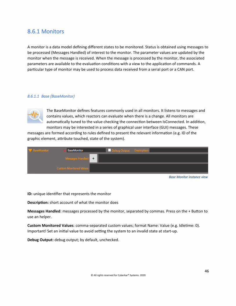
8.6.1.1 Base (BaseMonitor)
The BaseMonitor defines features commonly used in all monitors. It listens to messages and contains values, which reactors can evaluate when there is a change. All monitors are automatically tuned to the value checking the connection between IsConnected. In addition, monitors may be interested in a series of graphical user interface (GUI) messages. These
messages are formed according to rules defined to present the relevant information (e.g. ID of the graphic element, attribute touched, state of the system).
Fields
ID: unique identifier that represents the monitor
Description: short account of what the monitor does
Messages Handled: messages processed by the monitor, separated by commas. Press on the + Button to use an helper.
Custom Monitored Values: comma-separated custom values; format Name: Value (e.g. Idletime: 0). Important! Set an initial value to avoid setting the system to an invalid state at start-up.
Debug Output: debug output; by default, unchecked.
46© All rights reserved for Cyberkar® Systems. 2020
Base Monitor instance viewBase Monitor instance view

8.6.1.1.1 Messages Handled
To choose the message to handle in the monitor, ufor the right system componente, use the Message Handled dialog.
You can filter the liste with the Search field.
To add or remove a message, double-click or press the Add or Remove buttons, respectively.
Use the A-Z and Z-A buttons to list alphabetically or reverse the Message handled list.
8.6.1.1.1.1 OnGUIELEMENTNAME_ATTRIBUTEChanged
Description: The message OnGUIELEMENTNAME_ATTRIBUTEChanged allows to detect a change made to an attribute of a graphical interface item. The message consists of the prefix On, the ID of the interface element, a bottom dash, the attribute touched and Changed (e.g. OnButtonSRI_TextChanged). Affected attributes can be text, checked pressed toggle button status, etc.
Monitored value: ATTRIBUTEChanged (e.g. TextChanged, CheckedChanged)
Conditions: Conditions examining the value of the reviewed attribute may be applied (e.g. condition comparing the values M:ButtonVolumeMute_CheckedChanged and true to indicate what to do if ButtonVolumeMute is pressed). Another reactor could compare with the false value, to indicate what must be done when the button is not. In the case of a text comparison, M:TextChanged is compared with a text of choice (e.g. Mute), without specifying the ID of the user interface item.
47© All rights reserved for Cyberkar® Systems. 2020
Dialogue des messages traités

8.6.1.1.1.2 OnGUIELEMENTNAME_Click
Description: The OnGUIELEMENTNAME_Click message detects a pressure operated on a button or on atoggle button of the graphical interface. The message consists of the prefix On, the ID of the interface item, a bottom dash and Click (e.g. OnButtonVolumeDown_Click).
Monitored value: GUIELEMENTNAME_Click (press the button, the value is true ; after passing through the monitor, it is reset to false)
Conditions: Conditions examining the value true/false of the targeted button may be applied (e.g. condition comparing the values M:ButtonVolumeDown_Click and true). If there is no ambiguity between several buttons examined, we can simply compare M:Click with true/false.
8.6.1.1.1.3 OnGUIELEMENTNAME_TouchChanged
Description: The OnGUIELEMENTNAME_TouchChanged message detects a change in pressure operated (hold) on a button or on a toggle button of the graphical interface. The message consists of the Onprefix, the Interface Item ID, a bottom underline, and TouchChanged (e.g. OnStatusButton_TouchChanged).
Monitored value: GUIELEMENTNAME_TouchChanged
Conditions: Conditions comparing the M:GUIELEMENTNAME_TouchChanged value of the target buttonwith Up or Down can be applied (e.g. condition for comparison between the M:StatusButton_TouchChanged and Up values).
8.6.1.1.1.4 OnAppExited_APPID
Description: The OnAppExited_APPID message detects the closure of an application included in the configurator’s applications tab. APPID is replaced by the ID of the targeted application.
Monitored value: status of the targeted application.
Conditions: Conditions examining the status of the application may be applied (e.g. condition for comparison between M:Camera and Exited values).
8.6.1.1.1.5 OnAppStarted_APPID
Description: The OnAppStart_APPID message detects the start or display of an application included in the configurator’s applications tab. APPID is replaced by the ID of the targeted application.
Monitored value: status of the targeted application
Conditions: Conditions examining the status of the application may be applied (e.g. condition for comparison between M:Camera and Started values).
48© All rights reserved for Cyberkar® Systems. 2020

8.6.1.1.1.6 OnAppChildLinked_APPID
Description: The OnAppChildLinked_APPID message detects the start or display of the child process of an application included in the configurator’s applications tab. APPID is replaced by the ID of the targeted application.
Monitored value: status of the link to the child process
Conditions: Conditions examining the status of the link to child process may be applied (e.g. condition for comparison between M:VideoPlayer and ChildLinked).
8.6.1.1.1.7 OnAppChildWait_APPID
Description: The OnAppChildWait_APPID message detects the waiting status before the start of the child process of an application included in the configurator’s applications tab. APPID is replaced by the ID of the targeted application.
Monitored value: status of the link to the child process
Conditions: Conditions examining the status of the link to child process may be applied (e.g. condition for comparison between M:VideoPlayer and ChildWait).
8.6.1.1.1.8 OnAppChildLinkFailed_APPID
Description: The OnAppChildLinkFailed_APPID message detects the failure to link to the child process of an application included in the configurator’s applications tab. APPID is replaced by the ID of the targeted application.
Monitored value: status of the link to the child process
Conditions: Conditions examining the status of the link to child process may be applied (e.g. condition for comparison between M:VideoPlayer and ChildLinkFailed).
8.6.1.1.1.9 OnTabExited_NAME
Description: The OnTabExited_NAME message detects when a browser tab with a known name (NAME) is closed. NAME is the first parameter of the OpenURL and ShowURLTab commands.
Monitored value: status of the specified tab.
Conditions: Conditions examining the status of the application may be applied (e.g. condition for comparison between Google and Exited values).
49© All rights reserved for Cyberkar® Systems. 2020

8.6.1.1.1.10 Startup
Description: The Startup message detects the start of the Red Alert™ service and can be used to execute certain initialization commands.
Monitored value: status of the Red Alert™ service
Conditions: no associated conditions
8.6.1.1.1.11 ShutDownRequest
Description: The ShutDownRequest message detects a request to close the computer triggered by Red Alert™ (client).
Monitored value: system request
Conditions: no associated conditions
8.6.1.1.1.12 RestartRequest
Description: The RestartRequest message detects a request to restart the computer triggered by Red Alert™ (client).
Monitored value: system restart request
Conditions: no associated conditions
8.6.1.1.1.13 Custom
Description: The Custom message is triggered when the client sends a SendServiceMessage command. The parameter value of the command is transferred to a monitored value named Data.
Monitored value: Data
Conditions: Conditions examining the received text data may be applied (e.g. condition for comparison between M:Data and text values).
8.6.1.1.1.14 DataReceivedOn_PORTNUMBER
Description: The DataReceivedOn_PortNumber message is triggered when data is received on the specified port (e. g. CAN ou Serial port), including outdoor temperature and certain statuses. The PORTNUMBER goes after the underscore (e. g. DataReceivedOn_Can1, DataReceivedOn_COM4).
Monitored value: hexadecimal value (for CAN port) or alphanumeric text
50© All rights reserved for Cyberkar® Systems. 2020

Conditions: Conditions examining the values received may be applied (e.g. condition for comparison between X:MaskedValue and 0x00 values for CAN message).
8.6.1.1.1.15 UDPDataReceivedOn_PORTNUMBER
Description: The UDPDataReceivedOn_PORTNUMBER message is triggered when data is received on the specified port. The PORTNUMBER goes after the underscore (e. g. UDPDataReceivedOn_9094). The parameter value of the command is transferred to the values specified in the following format message: Monitoredvaluename1:value1;Monitoredvaluename2:value2;Monitoredvaluename3:value3
Monitored value: values specified in the message
Conditions: Conditions examining the values received may be applied (e.g. condition for comparison between values M:Monitoredvaluename1 and text).
8.6.1.1.1.16 OnPingResponse_PingServerCommandID
Description: The OnPingResponse_PINGSERVERCOMMANDID message is triggered when data is received after a Ping survey. The PINGSERVERCOMMANDID is the ID of the corresponding Ping Server command.
Monitored value: true/false boolean corresponding to the Ping survey response; the value is named as the command ID (e.g. PingLocal)
Conditions: Conditions examining the values received may be applied (e.g. condition for comparison between values M:PingLocal and true).
8.6.1.1.1.17 OnPortResponse_ScanPortCommandID
Description: The OnPingResponse_SCANPORTCOMMANDID message is triggered when data is receivedafter port verification. The SCANPORTCOMMANDID is the ID of the corresponding Scan port.
Monitored value: true/false Boolean corresponding to the verified Port response; the value is named as the command ID (p. ex. PortLocal80)
Conditions: Conditions examining the values received may be applied (e.g. condition for comparison between values M:PortLocal80 and true).
8.6.1.1.1.18 On_NetMotionState
Description: The On_NetMotionState message is triggered when the NetMotion® status changes. A custom monitored value must be added and initialized, NetMotionState:NOTINITIALIZED.
Monitored value: NetMotion® status (e.g. NOTINITIALIZED, DS_CONNECTING, DS_DISCONNECTED, DS_UNREACHABLE, DS_PASSTHRU)
51© All rights reserved for Cyberkar® Systems. 2020
Conditions: Conditions examining the values received may be applied (e.g. condition for comparison between values M:NetMotionState and DS_DISCONNECTED).
8.6.1.1.1.19 OnMultIPStatus_PropertyChanged
Description: The OnMultIPStatus_PropertyChanged message is triggered when the Mult-IP® status changes.
Monitored property: Mult-IP® status (e. g. ready, not responding)
Conditions: Conditions examining the values received may be applied (e.g. condition for comparison between values P:MultIPStatus and ready).
8.6.1.1.1.20 OnMultIPIP_PropertyChanged
Description: The OnMultIPIP_PropertyChanged is triggered when the Mult-IP® responding IP changes.
Monitored property: Mult-IP® responding IP
Conditions : Conditions examining the values received may be applied (e.g. condition for comparison between values P:MultIPIP and 24.37.205.166).
8.6.1.1.1.21 OnMultIPInterfaceName_PropertyChanged
Description: The OnMultIPInterfaceName_PropertyChanged is triggered when Mult-IP® responding network changes.
Monitored property: Mult-IP® responding network
Conditions: Conditions examining the values received may be applied (e.g. condition for comparison between values P:MultIPInterfaceName and LTE).
8.6.1.1.1.22 TimerTimeOut
Description: The TimerTimeOut message is used to trigger the monitor at the chosen frequency in the clock. The Timer is replaced by the ID of the clock and followed by TimeOut.
Monitored value: value with the same name (e.g. Timer1sTimeOut)
Conditions: Conditions examining the values received may be applied (e.g. condition for comparison between values M: Timer1sTimeOut and true).
52© All rights reserved for Cyberkar® Systems. 2020

8.6.1.2 With regular expressions (RegExMonitor)
The RegExMonitor uses a mask with a regular expression and the group of values resulting from the regular expression is accessible under the conditions and commands. It is useful when several values need to be analyzed by the monitor and when the value to be extracted does not have a fixed position (e.g. GPS data).
Fields
Regular Expression: a regular expression using standard language (see Microsoft website for more details about the language ; Wikipedia for common wildcards [e.g. replace < with <]). Example: ([asdf]*)(?<Speed>[\d.]*)([asdf]*).
Identify: The identifier is used to target a specific sequence. The monitor will then only be interested in the corresponding sequences. The identifier is automatically extracted from the data coming from the CAN port manager. The identifier must correspond to the first bytes of the sequence (e.g. $GPRMC).
Messages Handled: messages processed by the monitor (see those detailed in the basic monitor), separated by commas.
8.6.1.2.1 Regular Expression Dictionary (Regex)
The Regular Expression Dictionary provides the formulas most frequently used in the system, as the onesfor the GPS devices.
53© All rights reserved for Cyberkar® Systems. 2020
Regular Expression Dictionary (Regex)

8.6.1.3 Volume (VolumeMonitor)
The volume monitor is used to control the audio system. It automatically adjusts the volume level and manages the mute mode; the reactors can then be used at a certain interval (e.g. adjusting the level to 222 ms and the mute mode to 250 ms) so that the user interface accurately reflects the current state of the volume. The monitor is updated by receiving
system data and is independent of the interface.
Monitored value: VolumeLevel, VolumeMuted
Custom Monitored Values: Old-VolumeMuted:asdf (the value is instantiated after the first pass through the monitor)
Commonly associated interface items: VolumeMeter, ButtonVolumeMute
Typical volume monitor
8.6.1.4 Status Monitor
The Status Monitor allows you to group the vehicular computer statuses under the same monitor, to make it easier to locate in the configuration. In addition to the functionality of thebasic monitor, various statuses are tracked.
54© All rights reserved for Cyberkar® Systems. 2020

Status Monitor instance view
FieldsStatus: statuses that can be monitored; the monitored status is placed in a monitored value of the same name, for comparison in a reactor. Several statuses can be monitored at the same time, they are then separated by commas.
Statuses Description Possible valuesUNIT_SERIAL_NUMBER_READ_IX Serial number of the deviceFIRMWARE_RELEASE_DATE_IX Firmware Delivery DateCHARGING_STATUS Charging status NOT_CHARGING 0
WARMING_UP 1 MAINT_CHARGE 2 STANDARD_RATE 3 FAST_RATE 4 DISCHARGING 5
TELEMATIC_BOARD_VERSION_IX Telematic board versionTELEMATIC_BOARD_TYPE_IX Type of telematic boardWIRELESS_BOARD_ID Wireless board IDSMC_API_VERSION_IX SMC API versionFAN_ROUND_PERIOD_SECONDS Fan periodFAN_ROUND_ADJUST_FREQ_HZ Fan frequency (rpm)BATT_TEMP Battery temperatureBATT_VOLTAGE Battery voltageDIG_IN_CURRENT_STATE_D Current status of the digital
inputDIG_OUT_CURRENT_STATE_D Digital Output Current StatusSTC_RAW_ADC_VPWR Computer voltage powerSTC_RAW_ADC_BATT_PWR Computer battery powerSTC_RAW_ADC_GSM_PWR_INFO GSM Signal Level STC_RAW_ADC_BATT_TEMP Computer battery temperatureSTC_RAW_ADC_HDD_TEMP Computer hard drive
temperatureSTC_RAW_ADC_DVD_TEMP Computer DVD TemperatureBATT_PWR_MILLIVOLTS Battery power in millivolts TEMP_CELSIUS_CPU CPU temperatureTEMP_CELSIUS_HDD HDD temperatureTEMP_CELSIUS_CHARGER Charger temperatureTEMP_CELSIUS_MAINBOARD Motherboard temperature
55© All rights reserved for Cyberkar® Systems. 2020

Messages Handled: messages processed by the monitor (see those detailed in the basic monitor), separated by commas.
8.6.1.5 Brightness
The brightness monitor allows you to group the brightness controls under the same monitor, to make it easier to locate them in the configuration. This monitor sets the Cyberkar® screen current brightness value to a monitored Brightness value.
8.6.1.6 Digital
The Digital monitor allows you to group the digital input/output commands under the same monitor. To the functionalities of the basic monitor, the monitoring of various statuses of digital inputs and outputs, are added.
The various values that can be used in status correspond to the values of the Classic and Flex models (seeGet Digital IO for precise values).
Digital Monitor instance view
8.6.1.7 Model
8.6.1.7.1 Status Component
The Status Component Monitor Template automatically creates a series of monitors examining GPS data, vehicle speed, versions of Red Alert™ and configuration and allowing logs to be created for transmission to a remote database.
56© All rights reserved for Cyberkar® Systems. 2020
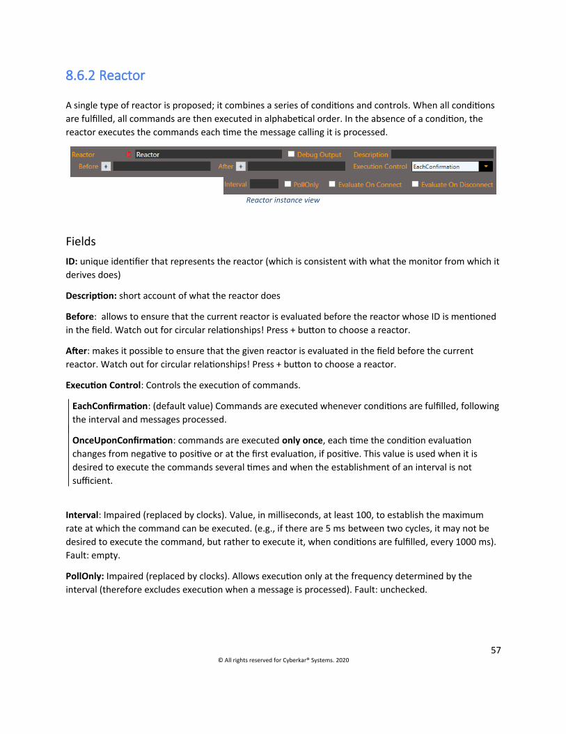
8.6.2 Reactor A single type of reactor is proposed; it combines a series of conditions and controls. When all conditions are fulfilled, all commands are then executed in alphabetical order. In the absence of a condition, the reactor executes the commands each time the message calling it is processed.
FieldsID: unique identifier that represents the reactor (which is consistent with what the monitor from which itderives does)
Description: short account of what the reactor does
Before: allows to ensure that the current reactor is evaluated before the reactor whose ID is mentioned in the field. Watch out for circular relationships! Press + button to choose a reactor.
After: makes it possible to ensure that the given reactor is evaluated in the field before the current reactor. Watch out for circular relationships! Press + button to choose a reactor.
Execution Control: Controls the execution of commands.
EachConfirmation: (default value) Commands are executed whenever conditions are fulfilled, followingthe interval and messages processed.
OnceUponConfirmation: commands are executed only once, each time the condition evaluation changes from negative to positive or at the first evaluation, if positive. This value is used when it is desired to execute the commands several times and when the establishment of an interval is not sufficient.
Interval: Impaired (replaced by clocks). Value, in milliseconds, at least 100, to establish the maximum rate at which the command can be executed. (e.g., if there are 5 ms between two cycles, it may not be desired to execute the command, but rather to execute it, when conditions are fulfilled, every 1000 ms). Fault: empty.
PollOnly: Impaired (replaced by clocks). Allows execution only at the frequency determined by the interval (therefore excludes execution when a message is processed). Fault: unchecked.
57© All rights reserved for Cyberkar® Systems. 2020
Reactor instance view

Evaluate On Connect: evaluation of the connection between the Red Alert™ client and their service. When the box is checked, the condition evaluation and the execution of commands are carried out only if the connection is established. Fault: unchecked.
Evaluate On Connect: Assessed when the Red Alert™ client is closed. Fault: unchecked.
Debug Output: debug output that also covers conditions and commands; by default, unchecked.
8.6.3 Conditions The conditions allow comparison of parameters monitored by the current monitor or other fixed values. These conditions may in particular be mathematical comparisons and expressions.
Condition instance view
Fields
ID: unique identifier that represents the comparison carried out.
8.6.3.1 Comparison
Comparison condition view
The comparison condition evaluates the value against a Boolean value (true/false), a numerical value (e.g. vehicle speed), a hexadecimal value, a text string (e.g. user group [administrator, guest]) or a monitored value.
Fields
Left Value: Left value in the comparison (usually the monitored value)
Right Value: Right value in comparison
Operator: Operator to be used in comparison (Equal, NotEqual, Smaller, SmallerOrEqual or GreaterOrEqual).
Note The string « M: » is placed in front of the monitored value. « X: » is placed in front of a hexadecimal value.
8.6.3.2 Bit Comparison
The Bit Comparison makes it possible to oppose two values by evaluating each of their bits.
58© All rights reserved for Cyberkar® Systems. 2020

Fields
Left Value: hexadecimal value to which you want to apply a mask (e.g. X:MaskedValue).
Right Value: mask to be applied to the left value. [0.1 or x to skip a bit] (e.g. xx001x01). A bit editor makes it possible to establish the mask to be used.
Operator: operator to be used in comparison (Equal, NotEqual).
The « X: » is placed in front of the monitored hexadecimal value.
8.6.3.3 MathExpression
The condition with mathematical expression works similarly to the comparison condition except that the left value is a mathematical expression. Semicolons (;) are used before and after the monitored values and hexadecimal values and after the operators (e.g. +;). Semicolons are not required at the beginning and end of the string. The condition can be used to convert velocity values to be compared: M:Speed;*1.60934 Smaller 2. In the left expression, you can use brackets (e.g. ="(3+;M:Speed;)*5-;M:Test) or hexadecimal values (e.g. X:MaskedValue;*;0x0a;+;1)
8.6.3.4 Time Condition
A Time Condition controls the minimum time that must elapse before a command is repeated. It is a question of determining the maximum rate of execution and not of a method of interrogation (clocks have this function). The time interval can be specified by two methods:
HH:MM:SS (e.g.: 0:0:10 corresponds to 10 seconds; 11:3:0 or 11:3 to 11 hours and 3 minutes) Time in milliseconds (e.g. 250 for 250 milliseconds; 2500 for 2.5 seconds).
8.6.4 Commands Commands are used to change the state of the client, service or system as well as to send data on a port.
Fields
ID: unique identifier that represents the command carried out.
59© All rights reserved for Cyberkar® Systems. 2020

8.6.4.1 General
8.6.4.1.1 Client Command Launch
The Client Command Launch is used to trigger a command entered in the Command tab. The concerned command is placed as a parameter using the button...
Client command view
Fields
Command: unique identifier that represents the targeted command.
8.6.4.1.2 Client Cancel Command
The Client Cancel Command allows you to cancel an order that has a lead time (e.g. 2000 ms). The order to be cancelled is set as a parameter using the … button.
Client Cancel command view
Fields
Command: unique identifier that represents the targeted command.
8.6.4.1.3 Manage Application
Manage Application commands can be used to start (StartApp), kill (KillApp), show (ShowApp) or close an application (CloseApp). The ID of the targeted application is presented as a parameter.
Application command view
Fields
ID: unique identifier that represents the targeted application.
8.6.4.1.4 Page Element Operation (GUI)
GUI commands allow to modify attributes of a targeted interface item.
60© All rights reserved for Cyberkar® Systems. 2020
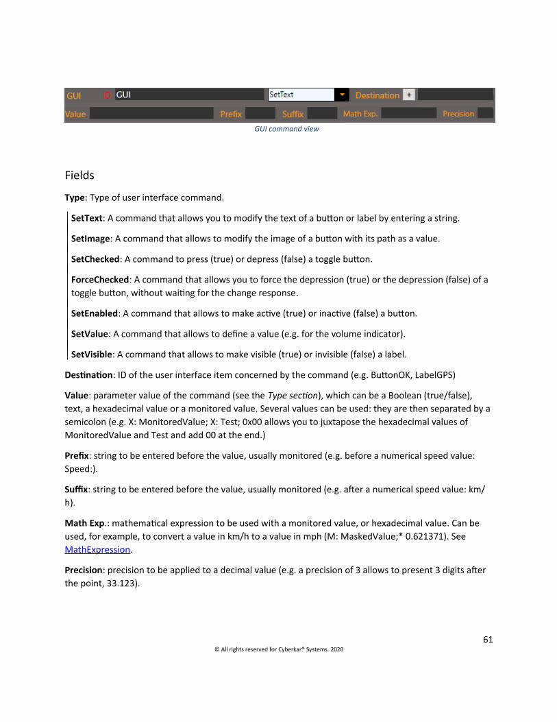
GUI command view
Fields
Type: Type of user interface command.
SetText: A command that allows you to modify the text of a button or label by entering a string.
SetImage: A command that allows to modify the image of a button with its path as a value.
SetChecked: A command to press (true) or depress (false) a toggle button.
ForceChecked: A command that allows you to force the depression (true) or the depression (false) of a toggle button, without waiting for the change response.
SetEnabled: A command that allows to make active (true) or inactive (false) a button.
SetValue: A command that allows to define a value (e.g. for the volume indicator).
SetVisible: A command that allows to make visible (true) or invisible (false) a label.
Destination: ID of the user interface item concerned by the command (e.g. ButtonOK, LabelGPS)
Value: parameter value of the command (see the Type section), which can be a Boolean (true/false), text, a hexadecimal value or a monitored value. Several values can be used: they are then separated by asemicolon (e.g. X: MonitoredValue; X: Test; 0x00 allows you to juxtapose the hexadecimal values of MonitoredValue and Test and add 00 at the end.)
Prefix: string to be entered before the value, usually monitored (e.g. before a numerical speed value: Speed:).
Suffix: string to be entered before the value, usually monitored (e.g. after a numerical speed value: km/h).
Math Exp.: mathematical expression to be used with a monitored value, or hexadecimal value. Can be used, for example, to convert a value in km/h to a value in mph (M: MaskedValue;* 0.621371). See MathExpression.
Precision: precision to be applied to a decimal value (e.g. a precision of 3 allows to present 3 digits after the point, 33.123).
61© All rights reserved for Cyberkar® Systems. 2020

8.6.4.1.5 Set Monitored Value
The Set Monitored Value command allows to adjust a value monitored by the current monitor, without triggering anything afterwards. It can make it possible to synchronize reactors and to write down their operating conditions.
Set Monitored Value command view
FieldsName: name of the monitored value to be adjusted, which will then be available to the conditions and commands.
Value: value to be given to the monitored value; several values can be specified by separating them by semicolons (;) (e.g. X:MonitoredValue;X:Test;0x00 will make it possible to correct the MonitoredValue and Test values and to add, at the end, 00).
Math Exp: mathematical expression used to generate the value (e.g. M:ExecutionCount;+; 1)
Bit Mask: mask of bits to be applied to the mathematical value or expression.
X: marks that value is of no interest
0: forces the value 0 to this position.
1: forces the value 1 to this position.
?: does not change the value at this position
Bit Order: allows to extract and reorders bits using the bit mask (Bit Mask) in correspondence with the order of the bits (Bit Order). In this case, the bit mask is composed of letters, and each letter identifies a bit. The identified bits are extracted from the data and placed in the order determined by the order of the bits (Bit Order), composed of the same letters. For example, with a bit mask of xxABCD and an order of bits of DCBA, the first two characters are skipped using x; the next 4 are reordered in reverse order. If the data were FFA, the result will be 5 (A is 1010 in binary; the reordering therefore gives 0101, which corresponds to 5).
8.6.4.1.6 Set Property Value
The Set Property Value command allows to modify property value for use it all around the configuration (and not only in the current monitor). The Property Manager will then manage this new property.
62© All rights reserved for Cyberkar® Systems. 2020
Set Property Value command view

HTTP Send command view
Champs
Name: property name(e. g. altitude)
Value: value to be given to the property, depending on the type of property
8.6.4.2 Communication
8.6.4.2.1 Config Report
The Config Report command is used to upload a configuration of Red Alert™ to the portal when the local version is different from the one mentioned in the portal, in order to quarantine the device.
8.6.4.2.2 HTTP Send
The HTTP Send command allows sending a JSON format file to an existing REST API using HTTPS protocol.
The JSON message sent to the selected server (e.g. portal) is dynamically constructed using the parameters of the command.
Fields
Code: a string specifying the code of the message (e.g. Telemetry, SoftwareVersion, SoftwareLogs), used to categorize messages in the database. Custom codes can also be defined.
DataType: a string specifying the type of data contained in the message (e.g. GPS), used to categorize thedata in the database.
Description: a description of the data sent in the message.
JSONReferences: list of data identifiers (tokens), with which a specific value or a monitored value is associated, separated by commas (e.g. gpsdate = February 12, 2018, latitude =M: latitude, longitude =M: longitude)
63© All rights reserved for Cyberkar® Systems. 2020
Config Report command view

8.6.4.2.3 Ping Server The Ping Server command allows Ping to survey an IP address or URL, which will respond with a Boolean (true/false) and transfer the value into a monitored value (this value, identical to the command ID must be added in the Custom Monitored Value; e.g. PingLocal).
A processed message (Message Handled) in another monitor in OnPingResponse_IDCommandPing format (e.g. OnPingResponse_PingLocal) will then allow actions to be performed, using conditions for comparison between M:PingLocal and true/false. See the format in the OnPingResponse_PingServerCommandID message.
Ping Server command view
Fields
Address: URL or ID address you want to ping.
8.6.4.2.4 Scan Port The Scan Port command checks whether a port is open; the Boolean result (true/false) is transferred intoa monitored value, which can be used by a tuned monitor.
The Message Handled in another monitor in OnPortResponse_IDCommandScan format (e.g. OnPortResponse_PortLocal80.) will then allow actions to be performed, using conditions for comparison between M:PortLocal80 and true/false. See the format in the OnPortResponse_ScanPortCommandID.
Scan Port command view
Fields
Address: URL or ID address you want to survey.
Port: port targeted by the audit (e.g. 80).
8.6.4.2.5 Send Message 112
The Send Message 112 command allows to build a binary message compatible with binary message received from NMEA monitors ($GPGGA $GPRMC). Message data comes from properties set in a RegEx monitor for GPS.
64© All rights reserved for Cyberkar® Systems. 2020

Serial command view
Champs
Type: type of the message to send in Red AlertTM (e. g., to send on port UDP 9999, SendUDPData_9999 )
Identifier: modem identifier (e. g. modem1)
8.6.4.2.6 Serial The Serial command allows you to write a message to send to a serial port using a reference value or a mathematical expression.
Fields
Type: SendSerialData_PORTNAME form command, where PORTNAME is replaced by the port identifier (e.g. Can2).
Value: Reference value to send when no mathematical expression is needed. Several values can be sent: they are then separated by a semicolon (;) (e.g. X:MonitoredValue;X:Test;0x00 will make it possible to correct the MonitoredValue and Test values and to add, at the end, 00).
Prefix: value added as a prefix (before) the command.
Suffix: value added in suffix (after) the order.
Math. Exp.: mathematical expression used to generate the command.
CRCType: algorithm used to process the (currently of type GD_CRC).
identifier: CAN identifier of the message to be sent (only for CAN ports).
BitMask: mask to be applied to the mathematical value or expression, composed of x, 0, 1 and ?.
X: marks that value is of no interest
0: forces the value 0 to this position.
1: forces the value 1 to this position.
?: does not change the value at this position
For example, with the mask xxxxxxx??10 applied to the value 0x080000;X:MaskedValue;0x000000000 ", we will skip the first 7, that is 080000, and the first of MaskedValue; the string ??10 will therefore be
65© All rights reserved for Cyberkar® Systems. 2020

UDP command view
effective for the second character of MaskedValue. Characters set to? will be kept as is and 1 will be forced on the third byte, and 0 on the fourth. The remainder will remain unchanged.
8.6.4.2.7 UDP The UDP command allows you to write a UDP message, using a reference value or the mathematical expressions, if desired.
Fields
Command: SendUDPData_PORTNUMBER type command, where the port number must be specified.
Value: reference value to send when no mathematical expression is needed (e.g. 080103). Several valuescan be sent: they are then separated by a semicolon (;) (e.g. X:MonitoredValue;X:Test;0x00 will make it possible to correct the MonitoredValue and Test values and to add, at the end, 00).
Prefix: value to be added before the command.
Suffix: value to be added after the command.
Math Exp.: mathematical expression to be used to format the data to be sent (e.g. GPS data).
8.6.4.3 VPN
8.6.4.3.1 NetMotion®
NetMotion® commands manage the connection with NetMotion® and report its status. They can be usedto connect (Connect), disconnect (Disconnect), communicate (PassThru) and to set the connection status(UpdateStatus) to a monitored value. Often, the connection is made from a toggle button and a monitor examines its change in order to update the status.
NetMotion® command view
Fields
Command: Type of NetMotion® command (Connect, Disconnect, PassThru, UpdateStatus).
66© All rights reserved for Cyberkar® Systems. 2020

Get Device Status command view
8.6.4.3.2 Mult-IP
The Mult-IP commands manage Mult-IP connection and report its status. Use it to connect (Connect), disconnect (Disconnect), or to get connection status (Status).
Fields
Command: type of Mult-IP command (Connect, Disconnect, Status).
8.6.4.4 System
8.6.4.4.1 Framework
The Framework command allows you to perform actions related to the framework (e.g. open all serial and CAN ports; close them). In Red Alert™, you can use Command ID OpenPorts and ClosePorts to do this.
Framework command view
Fields
Command: unique identifier that represents the control of the targeted framework.
8.6.4.4.2 Get Device Status
The Get Device Status command reports the connection status of a device.
8.6.4.4.3 Get Log
The Get Log command retrieves the customer, service or launcher log from Red Alert™ and places it in the corresponding monitored value (LogClient, LogService or LogLauncher)
67© All rights reserved for Cyberkar® Systems. 2020
Mult-IP® command view

Get Log command view
Fields
Log Origin: unique identifier that represents the targeted log (Client, Service ou Launcher).
8.6.4.4.4 Get Machine Name
The Get Machine Name command provides the name of the device (computer). This information can be displayed in an area, in the same way as the date and time, in the Fixed page.
Get Machine Name command view
8.6.4.4.5 Get Version
The Get Version command provides the Red Alert™ software version (e.g. 1.4.22), configuration (e.g. 1.4.26), and configuration GUID (e.g. 04556dcf-ee3c-4e3c-94d8-171d24d2d79b). Three custom monitored values must be instantiated to do this: RedAlertVersion, RedAlertConfigVersion and RedAlertConfigGUID.
Get Version command view
8.6.4.4.6 Restart The Restart command allows you to restart the computer (turn off and restart).
Restart command view
8.6.4.4.7 Shutdown The Shutdown command turns off the computer.
Shutdown command view
68© All rights reserved for Cyberkar® Systems. 2020

8.6.4.5 Cyberkar CPU
8.6.4.5.1 Get Digital IO
The Get Digital IO command allows to access the value of the digital inputs/outputs. The command sets the obtained value to a monitored value of the same name.
Get Digital IO command view
Fields
Value: targeted digital input/output (e.g. SMC_DIG_IN_1)
CLASSIC MODEL
SMC_DIG_IN_NONE
SMC_DIG_IN_1
SMC_DIG_IN_2
SMC_DIG_OUT_1
SMC_DIG_OUT_2
SMC_DIG_IN_3
SMC_DIG_IN_4
SMC_DIG_IN_5
SMC_DIG_IN_IGN
SMC_DIG_OUT_3
SMC_DIG_OUT_ALL
SMC_DIG_IN_ALL
SMC_DIG_OUT_NONE
SMC_DIG_OUT_ALL
FLEX MODEL
STC_DIG_IN_NONE
STC_DIG_IN_1
STC_DIG_IN_2
STC_DIG_IN_3
STC_DIG_IN_4_DIR
STC_DIG_IN_5_SPEED
STC_DIG_IN_IGN
STC_DIG_IN_6_ALARM
STC_DIG_IN_ALL
STC_DIG_OUT_NONE
STC_DIG_OUT_1
STC_DIG_OUT_2
STC_DIG_OUT_3
STC_DIG_OUT_4
STC_DIG_OUT_ALL
8.6.4.5.2 Set Brightness
Brightness command controls the brightness of the Cyberkar® screen. It is generally used in a settings page, with buttons to decrease the brightness, to increase it, to adjust in day or night mode. Start-up or shut-down commands for Red Alert™ can also be useful for multiple users on different shifts.
Brightness command view
FieldsValue: brightness value (can be -1 to decrease by one notch).
69© All rights reserved for Cyberkar® Systems. 2020

Set Digital IO command view
Min: minimum brightness value
Max: maximum brightness value
8.6.4.5.3 Set Digital IO
The Set Digital IO command allows you to adjust digital inputs/outputs.
FieldsIdentify: digital input/output identifier (e.g. SMC_DIG_IN_5)
Value: numerical value to be given for a SetValue command (e.g. 4, 10) or to be added for an Increment command (e.g. 1, -1)
Type: type of command, either to adjust the value (SetValue) or increment or decrement it (Increment).
Min: minimum input/output value
Max: maximum input/output value
8.6.4.5.4 Turn Off/On Screen
The Turn Off Screen and Turn On Screen commands turn off and turn on the Cyberkar® screen, respectively.
Turn Off Screen command view
Turn On Screen command view
70© All rights reserved for Cyberkar® Systems. 2020

8.7 NetMotion® Monitors
NetMotion® monitors operate in accordance with general monitors. See the Monitors section for details.
8.8 Ports management
8.8.1 Config Validation
The Config Validation Manager allows the Red Alert™ service to realize that a configuration change has taken place and to close automatically. The service can then restart with the new configuration. This manager is essential if the Launcher is used without administrator rights.
Config Validation Manager view
8.8.2 CAN Port
The computer's CAN port configuration allows data to be received and sent. The data received is monitored by processed messages of the DataReceivedOn_CanPortNumber type;data can be sent with a Serial.
Fields
RequiredService: validates that the specified service has started successfully. If the service has not, the check is repeated every 5 seconds to initiate data collection. (e.g. StcLinkSvc)
Can Extended Frame Format: determines if the CAN frame is in extended format. By default, the standard format is used.
Filter Can1: addresses of targeted CAN messages (e.g. 0x185, 0x703, 0x704)
Filter Can2: addresses of targeted CAN messages (e.g. 0x703, 0x704)
71© All rights reserved for Cyberkar® Systems. 2020
CAN port manager view

Bit Rate Can1: Can1 rate
CLASSIC (24 Mhz source clock)
CAN_CLK_24MHZ_125KBS_SP12PER16_MAXDLY4500NS CAN_CLK_24MHZ_250KBS_SP16PER24_MAXDLY1830NS CAN_CLK_24MHZ_500KBS_SP16PER24_MAXDLY917NS
FLEX (4MHz source clock)
CAN_CLK_4MHZ_125KBS_SP12PER16_MAXDLY4500NS
CAN_CLK_4MHZ_250KBS_SP12PER16_MAXDLY2250NS
CAN_CLK_4MHZ_500KBS_SP5PER8_MAXDLY750NS
Bit Rate Can2: Can2 rate. See Classic and Flex rates.
Use Can1: determines if Can1 is used.
Use Can2: determines if Can2 is used.
8.8.3 Property
The Property Manager allows to watch some global component in Red Alert™ across all monitors. The properties are settled with the Set Property Value command.
8.8.4 UDP Port
The computer's UPD port configuration allows data to be received and sent. The datareceived is monitored by processed messages of the UDPDataReceivedOn_PortNumbertype (where the port number corresponds to the specified Receiving Port and where themessage has the following form: Monitoredvaluename1:value1;
Monitoredvaluename2:value2;Monitoredvaluename3:value3); data can be sent with a UDP command(where the port number corresponds to the Sending Port).
UDP Manager view
72© All rights reserved for Cyberkar® Systems. 2020

Fields
Host: destination IP address of the computer you want to communicate with (e.g. 127.0.0.1)
Sending Port: port to which you want to send UDP data (e.g. 9999)
Receiving Port: tuned port, on which you want to receive UDP data (e.g. 9998)
8.8.5 Serial port
The configuration of the computer's serial data ports on a port. The port can for example be used to receive GPS data.
Serial Port manager view
Fields
Port: port of the computer where the data is sent (e.g. COM3)
BaudRate: speed of transmission (e.g. 9600)
Start Sequence: sequence marking the beginning of the data (e.g. $)
End Sequence: sequence marking the end of the data (e.g. \r\n)
8.8.6 NetMotion®
The NetMotion® manager reports the connection status with NetMotion®. In the monitors, the On_NetMotionState processed message allows to track the status of the service. By default, a NetMotion® monitor is added to a new configuration.
NetMotion® manager view
73© All rights reserved for Cyberkar® Systems. 2020

9 STEP-BY-STEP GUIDE
9.1 Customize the Fixed page
The Fixed page is created immediately when creating a new configuration; it cannot be deleted. This page can be easily customized by adding the client logo.
1. See the Pages tab.
2. If applicable, navigate to the Fixed page, the first page.
3. In the left column, select the Templates subtab.4. Scroll to Factory Template - Fixed Page5. Drag and drop this template to
the centre panel.
6. Go to the Image subtab.
7. Press Add Image...
8. Add the client logo.9. Press the Kommander™ logo (the image will then be framed in orange).10. Delete the logo.
11. Drag and drop the client logo where the Kommander™ logo was.
12. Adjust the image size as needed in the property editor.
74© All rights reserved for Cyberkar® Systems. 2020

10 TECHNICAL ASSISTANCECyberkar® Systems
3026 rue Anderson, suite 202
Terrebonne, Québec, Canada
J6Y 1W1
Phone: 450-951-3080
Fax: 450-823-0192
http://www.cyberkar.com
75© All rights reserved for Cyberkar® Systems. 2020


![BODY BUILDER™S DRAWINGS AND SUPPORTING … · BODY BUILDER™S DRAWINGS AND ... 6.2 Power source for electrical equipment of the body ... 12 {5.9 - 8.8} [N•m {ft.lbs}]](https://img.dokumen.tips/doc/110x75/5bc2578109d3f291178be722/body-builders-drawings-and-supporting-body-builders-drawings-and-62.jpg)