Embed Size (px)
Citation preview

KLM Technology
Group
Practical Engineering Guidelines for Processing
Plant Solutions
Solutions, Standards and Software
Page : 1 of 59
Rev: 01
Rev 01 – May 2015
KLM Technology Group #03-12 Block Aronia, Jalan Sri Perkasa 2 Taman Tampoi Utama 81200 Johor Bahru. Malaysia
Kolmetz Handbook Of Process Equipment Design
Plate Heat Exchanger Selection and Sizing
(ENGINEERING DESIGN GUIDELINE)
Co Authors
Rev 01 – Mela Widiawati
Author / Editor
Karl Kolmetz
TABLE OF CONTENT INTRODUCTION Scope 5 General Design Consideration 7 DEFINITION 21 NOMENCLATURE 23 THEORY
Heat Exchanger 24
KLM Technology Group has developed; 1) Process Engineering Equipment Design
Guidelines, 2) Equipment Design Software, 3) Project Engineering Standards and
Specifications, and 4) Unit Operations Manuals. Each has many hours of
engineering development.
KLM is providing the introduction to this guideline for free on the internet. Please
go to our website to order the complete document.
www.klmtechgroup.com

KLM Technology Group
Practical Engineering
Guidelines for Processing Plant Solutions
Kolmetz Handbook Of Process Equipment Design
Plate Heat Exchanger Selection and Sizing
(ENGINEERING DESIGN GUIDELINE)
Page 2 of 59
Rev: 01
Rev 01 – May 2015
These design guideline are believed to be as accurate as possible, but are very general and not for specific design cases. They were designed for engineers to do preliminary designs and process specification sheets. The final design must always be guaranteed for the service selected by the manufacturing vendor, but these guidelines will greatly reduce the amount of up front engineering hours that are required to develop the final design. The guidelines are a training tool for young engineers or a resource for engineers with experience. This document is entrusted to the recipient personally, but the copyright remains with us. It must not be copied, reproduced or in any way communicated or made accessible to third parties without our written consent.
Classification of Heat Exchanger by Flow Configuration 25 Classification of Heat Exchanger by Construction 28 Indirect Heat Exchanger 29 Plate Construction 39 Gasket Material 40 Flow Arrangement 40 Estimation of the Temperature Correction Factor 41 Heat Exchanger Coefficient 43 Overall Heat Transfer Coefficient 45 LMTD Method 46 Pressure Drop 46 Material of Construction 47 Maximum Pressure and Temperature Rating 48 Size Limitations 48 Fouling Factors 48 Condensing 49 Gas cooling 50 Evaporating 50 Laminar Flow 50 Comparing Plate and Tubular 52

KLM Technology Group
Practical Engineering
Guidelines for Processing Plant Solutions
Kolmetz Handbook Of Process Equipment Design
Plate Heat Exchanger Selection and Sizing
(ENGINEERING DESIGN GUIDELINE)
Page 3 of 59
Rev: 01
Rev 01 – May 2015
These design guideline are believed to be as accurate as possible, but are very general and not for specific design cases. They were designed for engineers to do preliminary designs and process specification sheets. The final design must always be guaranteed for the service selected by the manufacturing vendor, but these guidelines will greatly reduce the amount of up front engineering hours that are required to develop the final design. The guidelines are a training tool for young engineers or a resource for engineers with experience. This document is entrusted to the recipient personally, but the copyright remains with us. It must not be copied, reproduced or in any way communicated or made accessible to third parties without our written consent.
APPLICATION Example 1 : Investigate the use of a gasketed plate heat exchanger 53 REFERENCES LIST OF TABLE Table 1: Typical Fouling Factors for PHEs 13 Table 2: Characteristics of Some Gaskets Materials 15 Table 3: Typical Gasket Materials for Plate Heat Exchangers 37 Table 4: Typical Values of Fouling Coefficient and Resistances 51 LIST OF FIGURE Figure 1: Plate Heat Exchanger 9
Figure 2: Two Sections with Connector Plate 10
Figure 3: Plate and Frame Heat Exchanger 12
Figure 4: The Process and Service Fluid Flow Countercurrently
Between The Plates 13
Figure 5: Double Gasketing Prevent Fluids Mixing 15
Figure 6 : Countercurrent Flow 25 Figure 7 : Cocurrent Flow 26 Figure 8: Cross Flow 27 Figure 9 : Hybrids 28

KLM Technology Group
Practical Engineering
Guidelines for Processing Plant Solutions
Kolmetz Handbook Of Process Equipment Design
Plate Heat Exchanger Selection and Sizing
(ENGINEERING DESIGN GUIDELINE)
Page 4 of 59
Rev: 01
Rev 01 – May 2015
These design guideline are believed to be as accurate as possible, but are very general and not for specific design cases. They were designed for engineers to do preliminary designs and process specification sheets. The final design must always be guaranteed for the service selected by the manufacturing vendor, but these guidelines will greatly reduce the amount of up front engineering hours that are required to develop the final design. The guidelines are a training tool for young engineers or a resource for engineers with experience. This document is entrusted to the recipient personally, but the copyright remains with us. It must not be copied, reproduced or in any way communicated or made accessible to third parties without our written consent.
Figure 10 : Heat Exchanger Classifications 29 Figure 11 : Plate Exchanger Classification 31 Figure 12 : Plate Fin Heat Exchanger 32 Figure 13 : Spiral Heat Exchanger 33 Figure 14 : Shell and Tube Exchanger 39 Figure 15 : Plate and Frame Exchanger 39 Figure 16 : Plate Heat Exchanger Flow Arrangements 42 Figure 17 : Log Mean Temperature Correction Factor for Plate Heat
Exchangers 43 Figure 18 : Effect of Velocity and Turbulence 49

KLM Technology Group
Practical Engineering
Guidelines for Processing Plant Solutions
Kolmetz Handbook Of Process Equipment Design
Plate Heat Exchanger Selection and Sizing
(ENGINEERING DESIGN GUIDELINE)
Page 5 of 59
Rev: 01
Rev 01 – May 2015
These design guideline are believed to be as accurate as possible, but are very general and not for specific design cases. They were designed for engineers to do preliminary designs and process specification sheets. The final design must always be guaranteed for the service selected by the manufacturing vendor, but these guidelines will greatly reduce the amount of up front engineering hours that are required to develop the final design. The guidelines are a training tool for young engineers or a resource for engineers with experience. This document is entrusted to the recipient personally, but the copyright remains with us. It must not be copied, reproduced or in any way communicated or made accessible to third parties without our written consent.
INTRODUCTION Scope This design guideline covers the selection and sizing method for plate heat exchangers which are commonly used in typical industrial processes. It helps engineers, operations and maintenance personnel to understand the basic design of different types of heat exchangers, and increases their knowledge in selection and sizing. A heat exchanger is a device for heat transfer from one medium to another. The personnel needs to understand the terminology of the heat transfer equipment in order to properly design, specify, evaluate bids, and check drawings for this equipment. Heat transfer is one of the most important, as well as the most applied process, in chemical and petrochemical plants. Economics of plant operation often are controlled by the effectiveness of the use and recovery of heat or cold (refrigeration). The service functions of steam, power, refrigeration supply, and the like are dictated by how these service or utilities are used within the process to produce an efficient conversion and recovery of heat.
The basic plate heat exchanger consist of a series of thin, corrugated plates that are gasketed or welded together (or any combination of these) depending on the liquids passing through and on whether it is practical to be able to subsequently separates the plates, for whatever reason. The plates are then compressed together in a rigid frame to create an arrangement of parallel flow channels. One fluid travels in the odd numbered channels, the other in the even channels. All plate heat exchangers look similar from the outside. The differences lie inside, in the details of plate design and the sealing technologies used.
The basic concept of a heat exchanger is based on the promise that the loss of heat on the high temperature side is exactly the same as the heat gained in the low temperature side after the heat and mass flows through the heat exchanger. Heat exchanger simply exchanges the heat between those two sides; as a result, it is decreasing the temperature of higher temperature side and increasing the temperature of lower temperature side. But designing heat exchanger might be a challenge; it needs iteration for manual calculation. Hence, a guideline to properly select and sizing is needed.

KLM Technology Group
Practical Engineering
Guidelines for Processing Plant Solutions
Kolmetz Handbook Of Process Equipment Design
Plate Heat Exchanger Selection and Sizing
(ENGINEERING DESIGN GUIDELINE)
Page 6 of 59
Rev: 01
Rev 01 – May 2015
These design guideline are believed to be as accurate as possible, but are very general and not for specific design cases. They were designed for engineers to do preliminary designs and process specification sheets. The final design must always be guaranteed for the service selected by the manufacturing vendor, but these guidelines will greatly reduce the amount of up front engineering hours that are required to develop the final design. The guidelines are a training tool for young engineers or a resource for engineers with experience. This document is entrusted to the recipient personally, but the copyright remains with us. It must not be copied, reproduced or in any way communicated or made accessible to third parties without our written consent.
An innovative type of heat exchanger that has found widespread use is the plate and frame (or just plate) heat exchanger, which consists of a series of plates with corrugated flat flow passages. The hot and cold fluids flow in alternate passages, and thus each cold fluid stream is surrounded by two hot fluid streams, resulting in very effective heat transfer. Also, plate heat exchangers can grow with increasing demand for heat transfer by simply mounting more plates. They are well suited for liquid to liquid heat exchange applications, provided that the hot and cold fluid streams are at about the same pressure. General Consideration Plate type heat exchangers (PHE) consist of a number of parallel flow channels, formed by adjacent metal plates that are either welded or separated by gasket material around the perimeter of each plate. The plates can be formed from a variety of metals, but typically are made of stainless steel. The manufacturing process presses the plates into a corrugated shape that is different for each plate type and is proprietary to each manufacturer. The corrugations (sometimes called ribs or chevrons) both increase the mixing of the flow stream and add strength and support to the plate. The flow channel width between adjacent plates ranges from 0.05 to 0.25 in. (1.27 to 6.35 mm) and the ribs of adjacent plates have contact point with each other at regular intervals. PHEs can be designed for true counter flow because the hot and cold flow streams pass through adjacent channels over the entire length of the exchanger. This design allows closer approach temperatures than are possible with conventional shell and tube exchangers. The assembly of PHE facilities mechanical cleaning and allows the additional or removal of plates to increase or decrease the heat transfer surface area of the exchanger. The main advantages of PHE are their compact size and high heat transfer effectiveness that allow reduced number of units, smaller spaces and, for offshore platforms, and reduced weight. They are especially attractive in cost when the equivalent shell and tube exchanger would require in alloy shell or tubes. The minimum recommended construction material for all types of PHEs and welded PHEs is type 304 stainless steel. PHEs are presently operating in such liquid-liquid services as heat recovery loops, chemical process coolers and heaters, oil platform applications, and seawater cooling. Partially welded PHEs make good applications in product coolers using cooling water.

KLM Technology Group
Practical Engineering
Guidelines for Processing Plant Solutions
Kolmetz Handbook Of Process Equipment Design
Plate Heat Exchanger Selection and Sizing
(ENGINEERING DESIGN GUIDELINE)
Page 7 of 59
Rev: 01
Rev 01 – May 2015
These design guideline are believed to be as accurate as possible, but are very general and not for specific design cases. They were designed for engineers to do preliminary designs and process specification sheets. The final design must always be guaranteed for the service selected by the manufacturing vendor, but these guidelines will greatly reduce the amount of up front engineering hours that are required to develop the final design. The guidelines are a training tool for young engineers or a resource for engineers with experience. This document is entrusted to the recipient personally, but the copyright remains with us. It must not be copied, reproduced or in any way communicated or made accessible to third parties without our written consent.
The plate and frame heat exchanger is not specifically considered, because steady state design follows standard contraflow or parallel flow procedures. It is only necessary to source sets of heat transfer and flow friction correlations before proceeding. Plate and frame designs can be similar in flow arrangement to plate fin designs, but there is restriction on the piping manifold geometry. Optimization may proceed in a similar way as for compact plate fin heat exchangers, but is likely to be less comprehensive until universal correlations for the best plate panel corrugations become available. Significant features are composed of metal formed thin plates separated by gaskets. Compact, easy to clean. Application best suited are viscous fluids, corrosive fluids, slurries, high heat transfer. Limitation are not well suited for boiling or condensing; limit 35-500oF by gaskets. Used for liquid-liquid only; not gas-gas. Approximate relative cost in carbon steel construction 0.8 – 1.5. Inlet and return headering for plate and frame designs, and the same arrangement for plate fin designs, may add a phase shift to the outlet transient response following and inlet disturbance. Plate type exchangers consist of a number of parallel flow channels, formed by adjacent metal plates that are either welded or separated by gasket material around the perimeter of each plate. The plates can be formed from a variety of metals, but typically are made of stainless steel. The manufacturing process presses the plates into a corrugated shape that is different for each plate type and is proprietary to each manufacturer. The corrugation (sometimes called ribs or chevrons) both increase the mixing of the flow stream and add strength and support to the plate. The Frame The plate heat exchanger, as shown in Figure 1, consists of a stationary head and end support connected by a top carrying bar and bottom guide rail. These form a rigid frame, which supports the plates and moveable follower. In most units, plates are securely compressed between the head and follower by means of tie bars on either side of the exchanger. In a few models, central tightening spindles working against a reinforced end support are used for compression. When PHEs are opened, the follower moves easily along the top bar with the aid of a bearing supported roller, to allow full access to each individual plate. With the expectation of some sanitary models, which are clad with stainless steel, PHE frames are fabricated of carbon steel and finished in chemical resistant epoxy paint. Frame ports accept bushings of stainless steel or alternative metals, which with various

KLM Technology Group
Practical Engineering
Guidelines for Processing Plant Solutions
Kolmetz Handbook Of Process Equipment Design
Plate Heat Exchanger Selection and Sizing
(ENGINEERING DESIGN GUIDELINE)
Page 8 of 59
Rev: 01
Rev 01 – May 2015
These design guideline are believed to be as accurate as possible, but are very general and not for specific design cases. They were designed for engineers to do preliminary designs and process specification sheets. The final design must always be guaranteed for the service selected by the manufacturing vendor, but these guidelines will greatly reduce the amount of up front engineering hours that are required to develop the final design. The guidelines are a training tool for young engineers or a resource for engineers with experience. This document is entrusted to the recipient personally, but the copyright remains with us. It must not be copied, reproduced or in any way communicated or made accessible to third parties without our written consent.
types of flanged or sanitary connections, from the inlet and outlet nozzles. By using intermediate connector plates as shown in Figure 2, units can be divided into separate sections to accommodate multiple duties within a single frame.
Figure 1. Plate Heat Exchanger

KLM Technology Group
Practical Engineering
Guidelines for Processing Plant Solutions
Kolmetz Handbook Of Process Equipment Design
Plate Heat Exchanger Selection and Sizing
(ENGINEERING DESIGN GUIDELINE)
Page 9 of 59
Rev: 01
Rev 01 – May 2015
These design guideline are believed to be as accurate as possible, but are very general and not for specific design cases. They were designed for engineers to do preliminary designs and process specification sheets. The final design must always be guaranteed for the service selected by the manufacturing vendor, but these guidelines will greatly reduce the amount of up front engineering hours that are required to develop the final design. The guidelines are a training tool for young engineers or a resource for engineers with experience. This document is entrusted to the recipient personally, but the copyright remains with us. It must not be copied, reproduced or in any way communicated or made accessible to third parties without our written consent.
The Plates The closely spaced metal heat transfer plates have through or corrugations, which induced turbulence to the liquids flowing as a thin stream between the plates. The plates have corner ports, which in the complete plate pack from a manifold for even fluid distribution to the individual plate passage.
Figure 2. Two Section PHE with Connector Plate
The Gaskets The seal between the plates is established by a peripheral gasket which also separates the thru port and flow areas with a double barrier. The interspace is vented to atmosphere to prevent cross-contamination in the event of leakage. Gasketed plate and frame exchanger, in this type the plates are sandwiched together by an outside frame with tie rods that provide uniform sealing of the plate gaskets. The plates are 0.02 to 0.04 in (0.6 to 1 mm) thick. The size of the individual plates ranges from a minimum of approximately 0.5 ft x 1.5 ft (0.15 m x 0.46 m) to as large as 4 ft x 10 ft (1.220 m x 3.05 m). Plate and frame exchangers have heat transfer surface areas ranging from 5 to 13,000 ft2 (0.5 to 1210 m2).

KLM Technology Group
Practical Engineering
Guidelines for Processing Plant Solutions
Kolmetz Handbook Of Process Equipment Design
Plate Heat Exchanger Selection and Sizing
(ENGINEERING DESIGN GUIDELINE)
Page 10 of 59
Rev: 01
Rev 01 – May 2015
These design guideline are believed to be as accurate as possible, but are very general and not for specific design cases. They were designed for engineers to do preliminary designs and process specification sheets. The final design must always be guaranteed for the service selected by the manufacturing vendor, but these guidelines will greatly reduce the amount of up front engineering hours that are required to develop the final design. The guidelines are a training tool for young engineers or a resource for engineers with experience. This document is entrusted to the recipient personally, but the copyright remains with us. It must not be copied, reproduced or in any way communicated or made accessible to third parties without our written consent.
The maximum temperature and pressure limits on a gasketed PHE are approximately 450oF and 350 psia [230oC and 2400 kPa(a)]. Profile and Structure A typical plate and frame heat exchanger (sometimes referred to as a gasketed plate heat
exchanger) is shown in an exploded view in Figure 3. The PHE consist of an arrangement
of gasketed pressed metal plates (heat transfer surface), aligned on two carrying bars,
secured between two cover by compression bolts. Inlet and outlet ports for both hot and
cold fluids are stamped into the corners of each plate. The ports are lined up to form
distribution headers through the plate pack.
All four fluid connection are usually located in the fixed and cover. This permits opening
the exchanger without disconnecting any piping. Plates can be added and removes in the
field should service requirements change. The plates are pressed into one of a number
of available patterns and may be constructed of any material which can be cold formed
to the desired pattern. The welding characteristics of the plate material are not prime
importance since very little or no welding is involved in plate construction.

KLM Technology Group
Practical Engineering
Guidelines for Processing Plant Solutions
Kolmetz Handbook Of Process Equipment Design
Plate Heat Exchanger Selection and Sizing
(ENGINEERING DESIGN GUIDELINE)
Page 11 of 59
Rev: 01
Rev 01 – May 2015
These design guideline are believed to be as accurate as possible, but are very general and not for specific design cases. They were designed for engineers to do preliminary designs and process specification sheets. The final design must always be guaranteed for the service selected by the manufacturing vendor, but these guidelines will greatly reduce the amount of up front engineering hours that are required to develop the final design. The guidelines are a training tool for young engineers or a resource for engineers with experience. This document is entrusted to the recipient personally, but the copyright remains with us. It must not be copied, reproduced or in any way communicated or made accessible to third parties without our written consent.
1. Carrying bar 2. Connections 3. Fixed frame 4. Tightening bolt 5. End plate with 4 holes 6. Channel plates with 4 holes 7. End plate with all 4 ports blind 8. Pressure plate
Figure 3. Plate and Frame Heat Exchanger
1
2
3
4
5 6
7
8
KLM Technology Group
Practical Engineering
Guidelines for Processing Plant Solutions
Kolmetz Handbook Of Process Equipment Design
Plate Heat Exchanger Selection and Sizing
(ENGINEERING DESIGN GUIDELINE)
Page 12 of 59
Rev: 01
Rev 01 – May 2015
These design guideline are believed to be as accurate as possible, but are very general and not for specific design cases. They were designed for engineers to do preliminary designs and process specification sheets. The final design must always be guaranteed for the service selected by the manufacturing vendor, but these guidelines will greatly reduce the amount of up front engineering hours that are required to develop the final design. The guidelines are a training tool for young engineers or a resource for engineers with experience. This document is entrusted to the recipient personally, but the copyright remains with us. It must not be copied, reproduced or in any way communicated or made accessible to third parties without our written consent.
Gasket grooves are pressed into the plates as they are formed. The gaskets are generally
made of elastomers such as natural rubber, nitrile, butyl, neoprene, etc. the gasket
material chosen depends on the temperature, pressure, and chemical characteristics of
the fluid to which it will be exposed. The gasket cross section varies with different plate
designs and sizes. Rectangular, trapezoidal, or oval cross section are the most common.
The width is generally 5-15 mm, depending on spacing.
The height of the gasket before it compressed is 15 to 50% higher than the spacing,
depending on material, cross section of gasket, gasket track, and gasket hardness. When
the plate stack is compressed, the exposed surface of the gasket is very small. The gasket
are generally arranged in such a way that the through pass portal is sealed independently
of the boundary gasket. Leaks from one fluid to the other cannot take place unless a plate
develops a hole. Any leakage from the gaskets is to the outside of the exchanger where
it is easily detected.
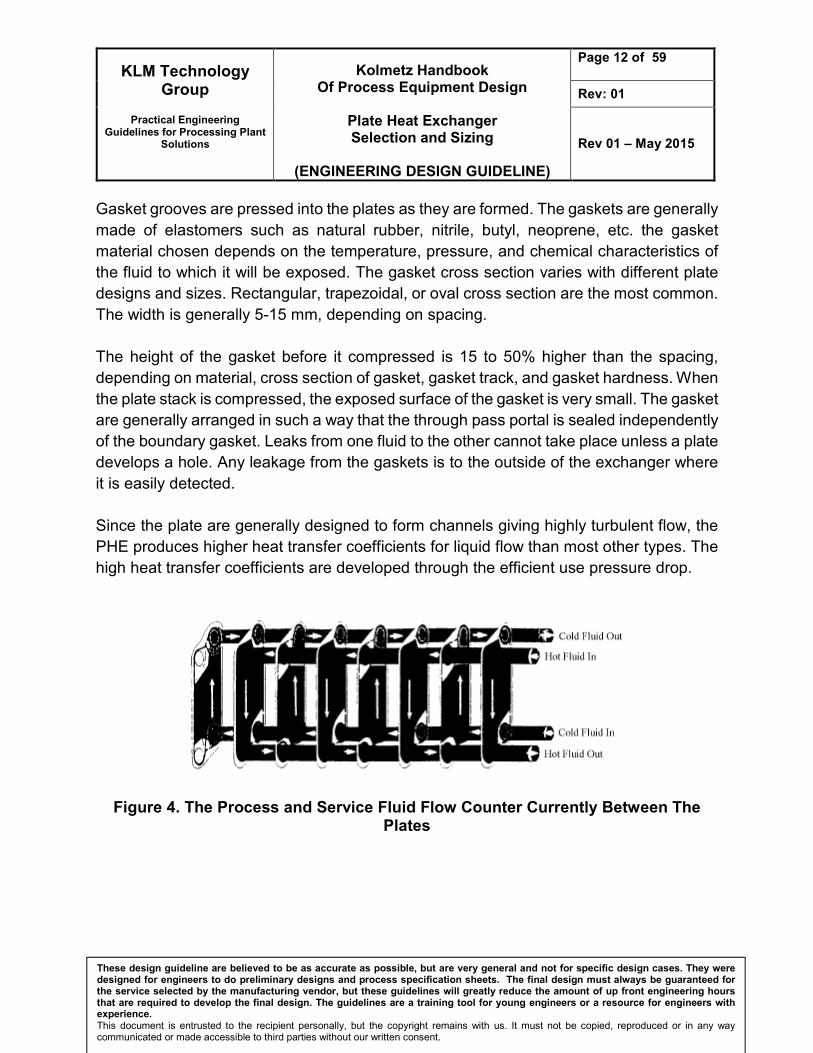
Since the plate are generally designed to form channels giving highly turbulent flow, the
PHE produces higher heat transfer coefficients for liquid flow than most other types. The
high heat transfer coefficients are developed through the efficient use pressure drop.
Figure 4. The Process and Service Fluid Flow Counter Currently Between The Plates

KLM Technology Group
Practical Engineering
Guidelines for Processing Plant Solutions
Kolmetz Handbook Of Process Equipment Design
Plate Heat Exchanger Selection and Sizing
(ENGINEERING DESIGN GUIDELINE)
Page 13 of 59
Rev: 01
Rev 01 – May 2015
These design guideline are believed to be as accurate as possible, but are very general and not for specific design cases. They were designed for engineers to do preliminary designs and process specification sheets. The final design must always be guaranteed for the service selected by the manufacturing vendor, but these guidelines will greatly reduce the amount of up front engineering hours that are required to develop the final design. The guidelines are a training tool for young engineers or a resource for engineers with experience. This document is entrusted to the recipient personally, but the copyright remains with us. It must not be copied, reproduced or in any way communicated or made accessible to third parties without our written consent.
By means of gaskets, the two fluids can be arranged in countercurrent flow, and flow volumes can be divided into a number of parallel streams. Gaskets seal the plates at their outer edges and around the ports, which are designed so that the inlet port can be at the top or bottom. Gaskets provide a double seal between the liquid streams. The interspace between the seals is vented to atmosphere, giving a visual indication of leakage and an escape path for the fluid. Some of the possible flow patterns in plate exchangers are illustrated in Figure 5. : (a) series flow, in which a continuous stream changes direction after each vertical path; (b) parallel flow, in which the stream divides and then re-converges; (c) a loop system, in which both streams flow in parallel; (d) and (e) other complex flow patterns. The number of parallel passages is mainly determined by the allowable pressure drop. Of course, the larger the number of parallel passages, the lower the pressure drop. The number of series passages is determined by plate efficiency and heat exchange requirements. If a liquid is cooled into viscous flow, the number of passages can be reduced to increase velocity.

KLM Technology Group
Practical Engineering
Guidelines for Processing Plant Solutions
Kolmetz Handbook Of Process Equipment Design
Plate Heat Exchanger Selection and Sizing
(ENGINEERING DESIGN GUIDELINE)
Page 14 of 59
Rev: 01
Rev 01 – May 2015
These design guideline are believed to be as accurate as possible, but are very general and not for specific design cases. They were designed for engineers to do preliminary designs and process specification sheets. The final design must always be guaranteed for the service selected by the manufacturing vendor, but these guidelines will greatly reduce the amount of up front engineering hours that are required to develop the final design. The guidelines are a training tool for young engineers or a resource for engineers with experience. This document is entrusted to the recipient personally, but the copyright remains with us. It must not be copied, reproduced or in any way communicated or made accessible to third parties without our written consent.
Figure 5. Double Gasketed Prevent Fluids Mixing The advantages and disadvantages of gasketed plate heat exchangers, compared with conventional shell and tube exchangers are listed below : Advantages
1. It can be easily be dissembled for cleaning.
2. The plates can be rearranged, added to, or removed from the plate rack for
difference service conditions.
3. The fluid residence time is short (low fluid volume to surface area ratio).
4. No hot or cold spots exist which could damage temperature sensitive fluids.
5. Fluid leakage between streams cannot occur unless plate material fails.
6. Fluid package due to a defective or damaged gasket is external and easily
detected.
7. Low fouling is encountered due to the high turbulence created by the plates.
8. A very small plot area is required relative to a shell and tube type heat exchanger
for the same service.

KLM Technology Group
Practical Engineering
Guidelines for Processing Plant Solutions
Kolmetz Handbook Of Process Equipment Design
Plate Heat Exchanger Selection and Sizing
(ENGINEERING DESIGN GUIDELINE)
Page 15 of 59
Rev: 01
Rev 01 – May 2015
These design guideline are believed to be as accurate as possible, but are very general and not for specific design cases. They were designed for engineers to do preliminary designs and process specification sheets. The final design must always be guaranteed for the service selected by the manufacturing vendor, but these guidelines will greatly reduce the amount of up front engineering hours that are required to develop the final design. The guidelines are a training tool for young engineers or a resource for engineers with experience. This document is entrusted to the recipient personally, but the copyright remains with us. It must not be copied, reproduced or in any way communicated or made accessible to third parties without our written consent.
9. The maintenance service area required is within the frame size of the exchanger.
Table 1. Typical Fouling Factors for PHEs
Fluid Fouling Factor (m2.h. oC/Kcal)
Water
Determineralized or distilled 0.000002
Municipal supply (soft) 0.000004
Municipal supply (hard) 0.00001
Cooling tower (treated) 0.000008
Sea (coastal) or estuary 0.00001
Sea (ocean) 0.000006
River, canal, borehole, etc. 0.00001
Engine jacket 0.000012
Oils, lubricant 0.000004 to 0.00001
Solvents, organic 0.000002 to 0.000006
Steam 0.000002
Process fluids, general 0.000002 to 0.000012
Disadvantages
1. Care must be taken by maintenance personnel to prevent damage to the gaskets
during disassembly, cleaning, and reassembly.
2. A relatively low upper design temperature limitation exists.
3. A relatively low upper design pressure limitation exists.
4. Gaskets materials are not compatible with all fluids.
KLM Technology Group
Practical Engineering
Guidelines for Processing Plant Solutions
Kolmetz Handbook Of Process Equipment Design
Plate Heat Exchanger Selection and Sizing
(ENGINEERING DESIGN GUIDELINE)
Page 16 of 59
Rev: 01
Rev 01 – May 2015
These design guideline are believed to be as accurate as possible, but are very general and not for specific design cases. They were designed for engineers to do preliminary designs and process specification sheets. The final design must always be guaranteed for the service selected by the manufacturing vendor, but these guidelines will greatly reduce the amount of up front engineering hours that are required to develop the final design. The guidelines are a training tool for young engineers or a resource for engineers with experience. This document is entrusted to the recipient personally, but the copyright remains with us. It must not be copied, reproduced or in any way communicated or made accessible to third parties without our written consent.
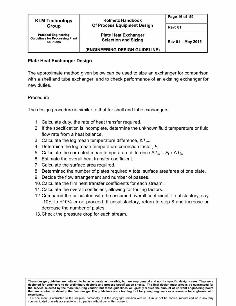
Plate Heat Exchanger Design
The approximate method given below can be used to size an exchanger for comparison
with a shell and tube exchanger, and to check performance of an existing exchanger for
new duties.
Procedure
The design procedure is similar to that for shell and tube exchangers.
1. Calculate duty, the rate of heat transfer required.
2. If the specification is incomplete, determine the unknown fluid temperature or fluid
flow rate from a heat balance.
3. Calculate the log mean temperature difference, ΔTlm.
4. Determine the log mean temperature correction factor, Ft.
5. Calculate the corrected mean temperature difference ΔTm = Ft x ΔTlm.
6. Estimate the overall heat transfer coefficient.
7. Calculate the surface area required.
8. Determined the number of plates required = total surface area/area of one plate.
9. Decide the flow arrangement and number of passes.
10. Calculate the film heat transfer coefficients for each stream.
11. Calculate the overall coefficient, allowing for fouling factors.
12. Compared the calculated with the assumed overall coefficient. If satisfactory, say
-10% to +10% error, proceed. If unsatisfactory, return to step 8 and increase or
decrease the number of plates.
13. Check the pressure drop for each stream.

KLM Technology Group
Practical Engineering
Guidelines for Processing Plant Solutions
Kolmetz Handbook Of Process Equipment Design
Plate Heat Exchanger Selection and Sizing
(ENGINEERING DESIGN GUIDELINE)
Page 17 of 59
Rev: 01
Rev 01 – May 2015
These design guideline are believed to be as accurate as possible, but are very general and not for specific design cases. They were designed for engineers to do preliminary designs and process specification sheets. The final design must always be guaranteed for the service selected by the manufacturing vendor, but these guidelines will greatly reduce the amount of up front engineering hours that are required to develop the final design. The guidelines are a training tool for young engineers or a resource for engineers with experience. This document is entrusted to the recipient personally, but the copyright remains with us. It must not be copied, reproduced or in any way communicated or made accessible to third parties without our written consent.
Table 2. Characteristics of Some Gaskets Materials
Gasket material Temperature (oC)
Service Remarks
Styrene-butadiene rubber
To 85 General-purpose for aqueous systems
Acrylonitrile butadiene rubber
To 140 Excellent resistance to aqueous systems fats and aliphatic hydrocarbons
Ethylene-propylene co-polymer
To 150 High-temperature resistance for a wide range of chemicals
Resin-cured butyl rubber
To 150 Excellent resistance to wide range of chemical, including acids, alkalis, ketones and amines
Poor, resistance to fats
Silicon rubber Low Limited to sodium hypochlorite and low temperatures generally
Fluoro-elastomer Above 150 Excellent for oils Use limited by high cost
Compressed asbestos fiber
To 250 Resistant to organic chemical mixture
Plates and frames must be stronger because of poor elasticity
Klingerlte To 250

KLM Technology Group
Practical Engineering
Guidelines for Processing Plant Solutions
Kolmetz Handbook Of Process Equipment Design
Plate Heat Exchanger Selection and Sizing
(ENGINEERING DESIGN GUIDELINE)
Page 18 of 59
Rev: 01
Rev 01 – May 2015
These design guideline are believed to be as accurate as possible, but are very general and not for specific design cases. They were designed for engineers to do preliminary designs and process specification sheets. The final design must always be guaranteed for the service selected by the manufacturing vendor, but these guidelines will greatly reduce the amount of up front engineering hours that are required to develop the final design. The guidelines are a training tool for young engineers or a resource for engineers with experience. This document is entrusted to the recipient personally, but the copyright remains with us. It must not be copied, reproduced or in any way communicated or made accessible to third parties without our written consent.
Plate Heat Exchanger Construction
A plate heat exchanger consist of a number of heat transfer plates which are held in place
between a fixed plate and a loose pressure plate to form a complete unit. Each heat
transfer plate has a gasket arrangement which provides two separate channel systems.
The arrangement of the gaskets (field and ring gaskets) results in through flow in single
channels, so that the primary and secondary media are in counter-current flow. The media
cannot be mixed because of the gasket design.
The plates are corrugated, which creates turbulence in the fluids as they flow through the
unit. This turbulence, in association with the ratio of the volume of the media to the size
of heat exchanger, gives an effective heat transfer coefficient.
Plate heat exchanger components
The components consist of a fixed end plate, connections and a loose pressure plate,
with carrier bars mounted between them. The plates are hung from the top carrier bar.
The carriers bar also serve to position the heat transfer plates. The single plates are pulled
together to form a plate pack by means of tightening bolts.
Gasketed plate heat exchangers are available in standard sizes or can be individually
prepared.
Gaskets
Material available
Nitrile rubber General purpose, oil resistant
EPDM General purpose, elevated temperatures
Heat Seal For high temperatures, specially heating by steam
KLM Technology Group
Practical Engineering
Guidelines for Processing Plant Solutions
Kolmetz Handbook Of Process Equipment Design
Plate Heat Exchanger Selection and Sizing
(ENGINEERING DESIGN GUIDELINE)
Page 19 of 59
Rev: 01
Rev 01 – May 2015
These design guideline are believed to be as accurate as possible, but are very general and not for specific design cases. They were designed for engineers to do preliminary designs and process specification sheets. The final design must always be guaranteed for the service selected by the manufacturing vendor, but these guidelines will greatly reduce the amount of up front engineering hours that are required to develop the final design. The guidelines are a training tool for young engineers or a resource for engineers with experience. This document is entrusted to the recipient personally, but the copyright remains with us. It must not be copied, reproduced or in any way communicated or made accessible to third parties without our written consent.
Brazed plate heat exchangers
A brazed plate heat exchanger is small, light and compact. It does not need gaskets.
Instead, it is brazed together using cooper to give a strong, compact construction.
This heat exchanger is especially suitable for pressure up to 50 bar and temperatures
from -196oC to +550oC.
Working Principle Channels are formed between the plates and the corner ports are arranged so that two media flow through alternate channels. The heat is transferred through the plate between the channels, and complete counter-current flow is created for highest possible efficiency. The corrugation of the plates provides the passage between the plates, supports each plate against the adjacent one and enhances the turbulence, resulting in efficient heat transfer. Evaluating plate heat exchangers All plate heat exchangers look similar on the outside. The difference lies on the inside, in the details of the plate design and the sealing technologies used. Hence, when evaluating a plate heat exchanger, it is very important not only to explore the details of the product being supplied, but also to analyze the level of research and development carried out by the manufacturer and the post commissioning service and spare parts availability. An important aspect to take into account when evaluating a heat exchanger are the forms of corrugation within the heat exchanger. There are two types: intermating and chevron corrugations. In general, greater heat transfer enhancement is produce from chevrons for a given increase in pressure drop and are more commonly used than intermating corrugation. Flow distribution and heat transfer equation Design calculations of a plate heat exchanger include flow distribution and pressure drop and heat transfer. The former is an issue of flow distribution in manifolds. A layout configuration of plate heat exchanger can be usually simplified into a manifold system with two manifold headers for dividing and combining fluids, which can be categorized into U-type and Z-type arrangement according to flow direction in the headers, as shown in manifold arrangement.

KLM Technology Group
Practical Engineering
Guidelines for Processing Plant Solutions
Kolmetz Handbook Of Process Equipment Design
Plate Heat Exchanger Selection and Sizing
(ENGINEERING DESIGN GUIDELINE)
Page 20 of 59
Rev: 01
Rev 01 – May 2015
These design guideline are believed to be as accurate as possible, but are very general and not for specific design cases. They were designed for engineers to do preliminary designs and process specification sheets. The final design must always be guaranteed for the service selected by the manufacturing vendor, but these guidelines will greatly reduce the amount of up front engineering hours that are required to develop the final design. The guidelines are a training tool for young engineers or a resource for engineers with experience. This document is entrusted to the recipient personally, but the copyright remains with us. It must not be copied, reproduced or in any way communicated or made accessible to third parties without our written consent.
DEFINITION Brazing – is a metal joining process whereby a filler metal is heated above melting point and distribute between two or more close fitting parts by capillary action. The filler metal is brought slightly above its melting temperature while protected by a suitable atmosphere, usually a flux. It then flows over the base metal (known as wetting) and is then cooled to join the workpieces together. It is similar to soldering, except the temperatures used to melt the filler metal are higher for brazing. Condensing – is the change of the physical state of matter from gas phase into liquid phase, and is the reverse of evaporation. Evaporation – is a type of vaporization of a liquid that occurs from the surface of a liquid into a gaseous phase that is not saturated with the evaporating substance. Fouling - The increased resistance to both heat transfer and fluid flow caused by deposits
on a heat transfer surface. Fouling works as an insulating layer on the heat transfer
surface, reducing heat transfer efficiency (reduced duty) or decreasing available flow area
(reduced throughput). The increased resistance to heat transfer is represented by a
quantity referred to as the fouling thermal resistance, which is added to the total thermal
resistance. The values of fouling thermal resistance have generally been observed to
increase with time. To account for the effect of fouling on pressure drop requires an
estimate of the fouling layer thickness.
Furnace – is a device used for high temperature heating.
Gasket is a mechanical seal which fills the space between two or more mating surfaces,
generally to prevent leakage from or into the joined objects while under compression.
Heater -A heater is any object that emits heat or causes another body to achieve a higher
temperature. In a household or domestic setting, heaters are commonly used to generate
heating
Pressure Drop – is defined as the difference in pressure between two points of a fluid
carrying network. Pressure drop occurs when frictional forces, caused by resistance to
flow, act on a fluid as it flows through the tube.
Superheater- is a device in a steam engine that heats the steam generated by the boiler again, increasing its thermal energy and decreasing the likelihood that it will condense

KLM Technology Group
Practical Engineering
Guidelines for Processing Plant Solutions
Kolmetz Handbook Of Process Equipment Design
Plate Heat Exchanger Selection and Sizing
(ENGINEERING DESIGN GUIDELINE)
Page 21 of 59
Rev: 01
Rev 01 – May 2015
These design guideline are believed to be as accurate as possible, but are very general and not for specific design cases. They were designed for engineers to do preliminary designs and process specification sheets. The final design must always be guaranteed for the service selected by the manufacturing vendor, but these guidelines will greatly reduce the amount of up front engineering hours that are required to develop the final design. The guidelines are a training tool for young engineers or a resource for engineers with experience. This document is entrusted to the recipient personally, but the copyright remains with us. It must not be copied, reproduced or in any way communicated or made accessible to third parties without our written consent.
inside the engine. Superheaters increase the efficiency of the steam engine, and were widely adopted. Steam which has been superheated is logically known as superheated steam; non-superheated steam is called saturated steam or wet steam. Superheaters were applied to steam locomotives in quantity from the early 20th century, to most steam vehicles, and to stationary steam engines including power stations.
Turbulence – is a flow regime characterized by chaotic property changes. This includes low momentum diffusion, high momentum convection, and rapid variation of pressure and flow velocity in space ad time.
Welding – is a fabrication or sculptural process that joins materials, usually metals or
thermoplastics, by causing coalescence.

KLM Technology Group
Practical Engineering
Guidelines for Processing Plant Solutions
Kolmetz Handbook Of Process Equipment Design
Plate Heat Exchanger Selection and Sizing
(ENGINEERING DESIGN GUIDELINE)
Page 22 of 59
Rev: 01
Rev 01 – May 2015
These design guideline are believed to be as accurate as possible, but are very general and not for specific design cases. They were designed for engineers to do preliminary designs and process specification sheets. The final design must always be guaranteed for the service selected by the manufacturing vendor, but these guidelines will greatly reduce the amount of up front engineering hours that are required to develop the final design. The guidelines are a training tool for young engineers or a resource for engineers with experience. This document is entrusted to the recipient personally, but the copyright remains with us. It must not be copied, reproduced or in any way communicated or made accessible to third parties without our written consent.
NOMENCLATURE A = area, (ft2) Cp = specific heat, (Btu/lb.oF) Cmax = maximum heat capacity (W/K) Cmin = minimum heat capacity (W/K) D = diameter, (in) F = LMTD correction factor f = friction factor G = mass velocity, (lb/ft2.s) H = height, (in) Hc = average heat transfer coefficient of cold fluid (W/m2K) Hh = average heat transfer coefficient of hot fluid (W/m2K) h = specific enthalpy (J/kg) k = thermal conductivity, (Btu/h.ft2.oF) L = length, (in) LMTD = Log Mean Temperature Difference, oF ṁ = mass flowrate, (lb/h) n = number constant N = number of exchangers Np = number of passes Nu = nusselt number NTU = number of heat transfer units ΔP = pressure drop, (lb/in2) P = pressure, (lb/in2) Pr = Prandtl number p = temperature efficiency PHE = plate and frame heat exchanger Q = heat transferred, (Btu/h) R = heat capacity rate ratio Re = Reynolds number T = temperature, (oF) t = temperature, (oF) U = overall heat transfer coefficient, (Btu/h.ft2. oF) W = width, (in) μ = viscosity, (centipoise) ρ = density,