Embed Size (px)
Citation preview

2015
KOHTECT qb701
LASER SHAFT ALIGNMENT SYSTEM
USER’S MANUAL

qb701 User’s Manual
2
CONTENT
General .................................................................................................................. 4
Safety Precautions ................................................................................................ 4
Laser Safety Precautions ........................................................................................ 4
EC Declaration of conformity .................................................................................. 5
Technical Description ................................................................................................ 6
Designation .......................................................................................................... 6
Misalignment Parameters ....................................................................................... 7
Specification and Features ...................................................................................... 8
System Package .................................................................................................... 9
System overview ................................................................................................... 9
Mounting Transducers .......................................................................................... 10
Laser Beam Adjustment ....................................................................................... 11
Getting Started ...................................................................................................... 12
Common control keys consideration ...................................................................... 12
Auto save ........................................................................................................... 12
Device setup....................................................................................................... 12
setup Menu Items ............................................................................................... 13
Horizontal Machine Alignment .................................................................................. 15
Short Explanation ................................................................................................ 15
Transducer’s Positions Conventions ....................................................................... 15
Parameters ......................................................................................................... 16
Taking Measurements. Clock Mode ........................................................................ 18
Taking Measurements. Multipoint Mode .................................................................. 20
Result Screen ..................................................................................................... 21

qb701 User’s Manual
3
Movable machine Adjustment ............................................................................... 21
Save Report ....................................................................................................... 23
Charging batteries ............................................................................................... 24
Firmware Upgrade ............................................................................................... 25
Firmware Upgrade Using Windows Mobile Device Center .......................................... 27
Standard Tolerances of Shaft Misalignment ............................................................... 29
Delivery Set .......................................................................................................... 30

qb701 User’s Manual
4
GENERAL
SAFETY PRECAUTIONS
Be sure the machines to be measured, cannot be started unintentionally as this can cause
injuries. For this purpose, before the mounting of equipment, either block the power switch
in the “Off” position or remove the safety fuses. These precautionary rules must be
followed until the measuring system is dismantled from the measured machine.
LASER SAFETY PRECAUTIONS
The KOHTECT qb701 alignment system is the class II laser device at typical wavelength of
670nm, delivered output power of less than 1 mW and maximum radiant energy per pulse
of 0.1 mJ. The Class II laser comply with requirement outlined by USA’s FDA as well as
international ANSI, BS 4803 and IEC 825 standard. Be sure to follow the following safety
precautions to avoid personal injuries and damage to the system
Do not look directly into the laser beam at any time!
Do not direct laser beam on to the people’s eyes!
ATTENTION!
Do not expose qb701 parts to heavy impacts, high humidity and extreme temperature.
Do not try open / dismantle measuring units and the display unit – this can damage the
system, and your after-sales service warranty will come void.
INJURY RESPONSIBILITY DISCLAIMER
Neither the NPP KOHTECT enterprise nor our authorized dealers are liable for the damages
caused to machinery or equipment by use of the qb701 system. We carefully check text of
this manual to eliminate errors, nonetheless there may be mistakes or inaccuracy involved.
We will be grateful for your reporting to us about any error, and we will be able to correct
them in the subsequent editions of the manual.

qb701 User’s Manual
5
EC DECLARATION OF CONFORMITY
We, NPP KOHTECT, 124A, Kosmonavtov str., Nikolaev, Ukraine herewith declare
that the following product:
Shaft Alignment Tool qb701
has been designed and manufactured in accordance with: EMC DIRECTIVE
2004/108/EC as outlined in the harmonized norm for EN 61326-1:2013 Electrical
equipment for measurement, control and laboratory use –
Part 1: General Requirements,
EN 55011: 2009 +A1:2010, EN 61000-4-2: 2009, EN 61000-4-3: 2006 +A1:2008
+A2:2010, EN 61000-4-4: 2004 +A1:2010, EN 61000-4-5: 2006, EN 61000-4-6:
2009, EN 61000-4-11: 2004
EUROPEAN ROHS DIRECTIVE 2011/65/EU
The laser is classified in accordance with the EN 60825-1:2007. The laser complies
with 21 CFR 1040.10 and 1040.11 except for deviations pursuant to Laser Notice
No. 50, dated June 24, 2007.
The enclosed device complies with Part 15 of the FCC Rules.
47CFR: 2011 Part 15 Sub Part B Unintentional Radiators. Contains FCC ID: QOQWT11IA,
contains IC: 5123A-BGTWT11IA. Manufacturer’s Name, Trade Name or Brand Name:
Bluegiga. Model Name: WT11i.
Kiev, Ukraine, Dec 17, 2015
Oleg Ivanov, Head of Product Development

qb701 User’s Manual
6
TECHNICAL DESCRIPTION
DESIGNATION
qb701 alignment system (further as System) is designed for measurement of shaft axis
misalignment of coupled machines, and calculation of movable machine adjustment
required to eliminate misalignment that exceeds permissible tolerances;
The machine alignment means adjustment of the relative position of two coupled machines
(e.g. motor and pump) so that the center line of the axis will be concentric when the
machines are running under normal working conditions.
S transducer
installed on the
shaft of Stationary
machine
M transducer
installed on the
shaft of the
machine to be moved

qb701 User’s Manual
7
S – stationary machine M – moveable machine
Shaft Angular (Gap)
value
Shaft Parallel (Offset)
value
Vertical adjustment values
S M
MISALIGNMENT PARAMETERS
Misalignment of any rotating machine is expressed in parallel (Offset) and angular (Gap) of
the shafts. Most frequently in practice, both of them are present simultaneously. Different
kinds of misalignment of axes are shown in Fig. 2.
The parallel (Offset) and angular (Gap) misalignment of axes is determined in two
mutually perpendicular planes. For the purpose of elimination of the parallel and angular
misalignment of axes, in each of the planes a correction of position of the movable
machine (M) will be done.
For the horizontal mounted machine – the movable machine (M) position is adjusted in the
horizontal and vertical planes.
For the vertical mounted machine, operator determines arrangement of the correction
planes, basing on considerations of the convenience and technological effectiveness of
moving of the movable (M) machine.
Stationary machine (S) - in the process of eliminating of the axes misalignment the
position of this machine stay static, i.e. it does not move.
Movable machine (M) – the machine, which position is adjusted for eliminating of the
parallel and angular misalignment of axes.
The measurement system calculates the values of the angular and parallel misalignment of
axes in the plane of the coupling (in two mutually perpendicular planes), and the
adjustment values for the machine feet on the movable (M) machine, that is necessary for
elimination of this misalignment of axes. Fig. 3 shows misalignment of axes and the values
for its correction just for vertical plane.
Parallel misalignment of axes – Offset (displacement)
Angular misalignment of axes – Gap
Parallel and angular misalignment of axes – (Offset + Gap)
Fig 2

qb701 User’s Manual
8
SPECIFICATION AND FEATURES
- Separation distance between measuring transducer units, up to 3 m
- Display control operating temperature range, -10..+55 degree C
- Measurement accuracy, 1%+0.01
- Laser type: Visible red 635-670 nm, <1 mW
- Detector type: Positional-sensitive photodiodes, length 24 mm
- Display resolution, 0.01 or 0.001 mm, (1 or 0.1 mil )
- Measuring resolution, 0.001mm
- Electronic inclinometer resolution, 0.1 degree
- Power supply: Rechargeable LiPo battery
- Gross weight, incl. carry case, 4.5 kg
- Built-in application programs and options:
o horizontal shaft alignment at any shaft position, from 60°, up to 360º, up to 36
readings can be measured; auto sweep mode can be used;
o vertical (flange machine) shaft alignment;
o editable misalignment tolerances;
o setup options;
o soft foot;
o thermal growth;
o shimming simulator to calculate for expected residual misalignment;

qb701 User’s Manual
9
3
1
4
2
5
8
SYSTEM PACKAGE
The System includes (Fig. 1):
1- AVV-711 display unit
2- two measuring transducer units – S, M
3- universal chain brackets for mounting of
measuring units S, M
4- measuring tape
5- 120…240 Volts AC charger
6- USB PC communication cable
7- Operating instructions manual and ConSpect
freeware on the internal drive of display unit
8- Carrying case with form-inserted
SYSTEM OVERVIEW
Locking
thumb nut
Mini USB
charger
connector
Detector
window
Laser
aperture
Power
button

qb701 User’s Manual
10
4
1
3
2
5
1
MOUNTING TRANSDUCERS
Firmly tighten rods 1 into the shaft brackets 2.
Put thumb nut 3 into the bracket 2, then hook the chain 5 on the stud 4.
Firmly tighten the thumb nut 3. Shaft brackets with rods must be mounted at the
same angular position.
Mount transducers on the rods. Always try to mount transducers at minimal
possible radial height. Make sure that transducers are not touching brackets or
machine parts.
S, M transducers to be
installed at the same
height with labels faced up
Datum lines for measuring
of dimension input
Locking
thumb nut
M transducer
installed on
the machine
to be moved
S transducer
installed on
the stationary machine

qb701 User’s Manual
11
LASER BEAM ADJUSTMENT
Loosen thumb nut and horizontally adjust transducer so the middle of the laser line
is at the transducer’s window.
Slightly tighten thumb nut then vertically adjust laser line to the center of the
transducer’s window.
Firmly tighten the thumb nut.
Adjust second transducer in the same way.
Use an angular adjustment only. Do not change transducers installation height!
Locking
thumb nut

qb701 User’s Manual
12
GETTING STARTED
COMMON CONTROL KEYS CONSIDERATION
To turn ON/OFF display unit and transducers – press and hold the power button for
~2 sec.
In case the system hangs and device did not respond to any keys - press and hold the
power button for ~10 sec, the system will be reset.
To close any currently active window, without saving, except main menu of the device,
press button (it serves as escape key).
The button in most cases causes applying(saving) changes (invoke selection) and exit
(from edit box; or from current window, except such windows as collect data, aligning, soft
foot and so on where it not applicable).
To invoke menu item – move cursor to this item and press key, or just press the
shortcut key regardless of the cursor position. In most cases the shortcut key is depicted
left to the menu item.
AUTO SAVE
All procedures are designed with auto save. For temporarily shut down your current work
press until program exits to main menu of the device. Data saved now and device can
be turned off.
DEVICE SETUP
To invoke Setup menu – move cursor to Setup
icon and press button, or press key.

qb701 User’s Manual
13
Serial
number
+ Function
enabled,
valid till
01.01.2099
Number of
transducers to
be connected
SETUP MENU ITEMS
– to setup date and time
– to set device auto off delay in seconds. When set
to 0 – auto off is disabled.
– to install license file which enables
measurement functions. Press 9, browse
to the license file, press Enter to open
and install licenses.
– to switch between wireless/cable transducers
connection. For wireless connection – press 1 or 2 to
enter number of transducers to be connected

qb701 User’s Manual
14
– to choose user interface language
Use keys to choose language, then press
– to switch qb701 into USB mass
storage device mode. By default device can be
connected to the PC via Microsoft Windows Mobile
Device Center. USB mass storage device mode can
be used as alternative.
– to adjust the display backlight brightness

qb701 User’s Manual
15
HORIZONTAL MACHINE ALIGNMENT
SHORT EXPLANATION
o Mount transducers on shafts
o Run Horizontal program
o Enter dimensions
o Set parameters. E.g. Measurement mode – clock type (9-12-3 o’clock positions)
o Turn shafts with transducers at first position 9 o’clock (90°). Press Start to take
readings
o Turn shafts with transducers at second position 12 o’clock (180°). Press Start to
take readings
o Turn shafts with transducers at last position 3 o’clock (270°). Press Start to take
readings
o After that device will calculate misalignment and displays required corrections for
Movable machine
TRANSDUCER’S POSITIONS CONVENTIONS
While taking measurements, it is necessary to
follow conventions for transducers positions on
the shafts with the S and M measuring
transducers with regard to the relative position of
the S and M machines as depicted on the figure.
Angular positions in degrees adopted in the
device are as follows:
6 o’clock - 0°
9 o’clock - 90°
12 o’clock - 180°
3 o’clock - 270°
9
3
12
S M
6
qb701 User’s Manual
16
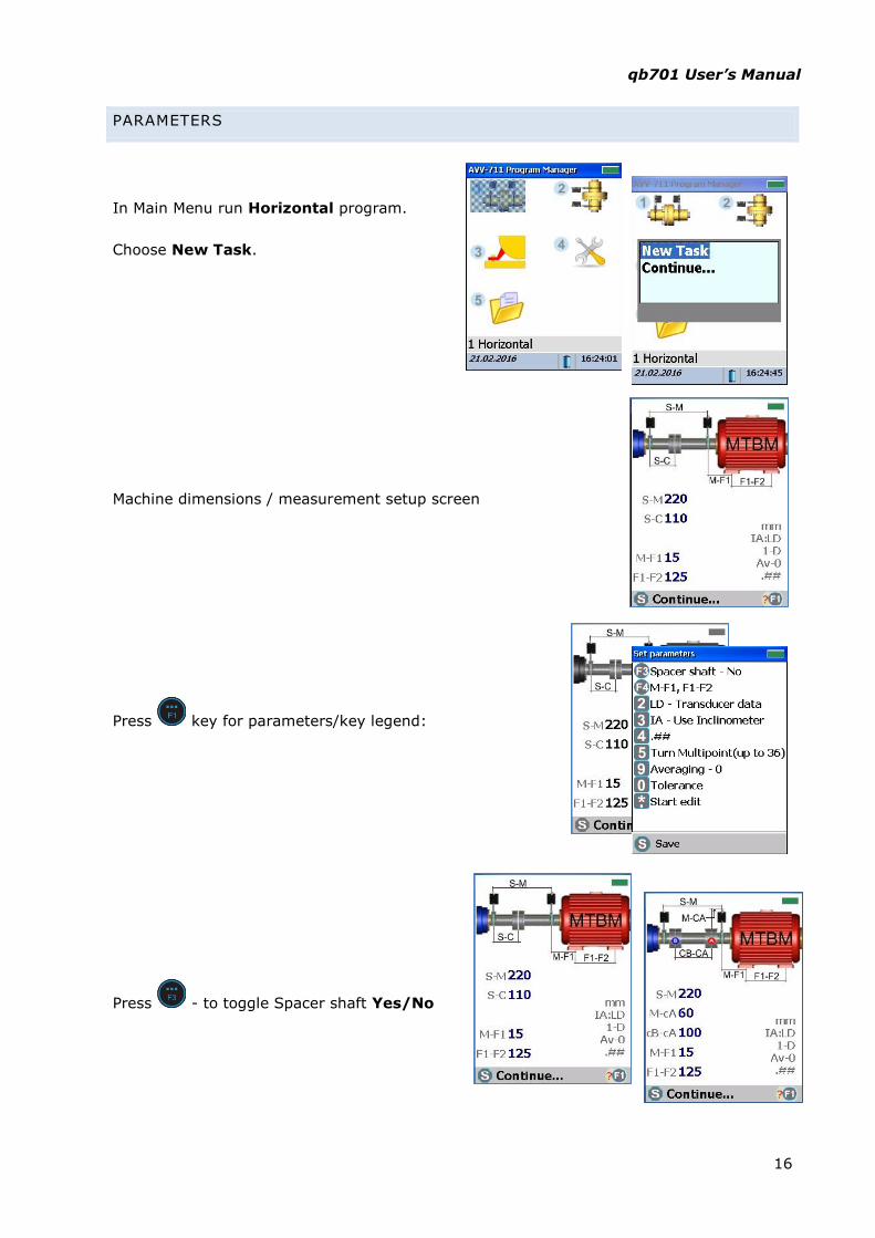
PARAMETERS
In Main Menu run Horizontal program.
Choose New Task.
Machine dimensions / measurement setup screen
Press key for parameters/key legend:
Press - to toggle Spacer shaft Yes/No

qb701 User’s Manual
17
Press - to toggle dimensions input
M-F1, M-F2 / S-F1, S-F2
Press - to toggle data input – LD transducer’s data / MD – manual data
Press - to toggle angle input – IA use inclinometer / MA manual angle. Manual angle
input used for vertical machines, when electronic inclinometer cannot be used.
Press - to toggle displayed precision – 2 or 3 digit.
Press - to toggle measurement mode: Clock
mode 9-12-3 o’clock – readings to be taken at
three predefined shaft positions – 9 o’clock, then
12 o’clock, then 3 o’clock. After that device itself
will proceed to the result screen.
Multipoint mode – measurements may be taken
at any minimum 3 up to 36 positions. After taking
enough readings one should press to proceed to the result screen.
Press to enter tolerance setup menu.
Press to use predefined RPM/tolerance table
Press to enter user defined tolerance values
Press to save changes, to discard changes.
9
3
12
S M

qb701 User’s Manual
18
TAKING MEASUREMENTS. CLOCK MODE
Press to edit dimensions.
Set parameters and enter dimensions then press key to
proceed.
Turn shafts to first position – 9 o’clock (90°)
Press to take first reading.
Turn shafts to second position – 12 o’clock (180°)
First
measurement
3 – clock mode
* – multipoint S
M
12
S M

qb701 User’s Manual
19
Press to take second reading.
Turn shafts to third/last position – 3 o’clock (270°)
Press to take third reading.
When three reading are taken device will proceed to the result
screen.
S
M

qb701 User’s Manual
20
TAKING MEASUREMENTS. MULTIPOINT MODE
In multipoit mode readings can be collected at any shafts position minimum 3 up to 36
positions.
qb701 is able to calculate misalignment after collecting at least 3 points within as little as
70 degree range. However always try to cover as wide shaft turn angle as possible.
Press to take reading, and then turn
shafts to next position.
Yellow clock face means that point is already
collected and shafts should be turned to next
position.
When enough readings are collected – press to proceed to the
result screen.

qb701 User’s Manual
21
RESULT SCREEN
On the result screen device displays parallel and angular misalignment at the coupling and
values of the required corrections in horizontal and vertical directions for movable
machine. Blue arrows clearly displays directions in which movable machine must be moved
to eliminate misalignment.
MOVABLE MACHINE ADJUSTMENT
To make adjustment in vertical direction
transducers must be turned to 6 or 12 o’clock (0°
or 180°) position.
To make adjustment in horizontal direction
transducers must be turned to 9 or 3 o’clock (90°
or 270°) position.
Horizontal adjustment:
Top view at the
Movable machine
Vertical adjustment:
Side view at the Movable machine
Values and directions
of adjustment for Front and Rear feet
Parallel and angular
misalignment at the coupling
S
M
12
S M

qb701 User’s Manual
22
Device may reduce number of available transducers positions for machine adjustment.
Permissible transducer positions are indicated at the clock face. Only permissible
transducer positions can be used for machine adjustment.
Permissible transducer
positions –
12, 6 – for V direction 3 – for H direction
Transducers now at
3 o’clock (270°) live data for H direction
Data for V direction are
frozen (display shaded)
until transducers are not turned to 12 or 6 o’clock

qb701 User’s Manual
23
SAVE REPORT
To save report – press key in the result screen
To save report at current location – press or
key. To browse to different location – press
, choose folder, then press key.

qb701 User’s Manual
24
USB type
charger
connector
CHARGING BATTERIES
The battery can be charged by means
of USB type AC charger or via
PC/laptop USB port.
Immediately after connecting charger
to the display unit there are few
seconds to change charge current -
press and hold ON button for ~2sec
until LED changes flash rate.
Low flash rate – normal
charge, high rate – fast
charge. Keep in mind that
PC/laptop USB port can
only provide normal
charge.
The LED will turns off
when battery is fully
charged.
USB type
charger
connector
USB type
charger
connector

qb701 User’s Manual
25
FIRMWARE UPGRADE
Make sure that device battery is fully charged!
1. Insert USB thumb drive into PC/Laptop port. In the root
directory of USB thumb drive – create the folder
AvvUpd.ate
2. Copy firmware file Avv711Intall.cab to this folder
3. Remove USB thumb drive from PC/Laptop port and insert it to the qb701 USB host
port. Press and hold key for ~2 sec to turn qb701 on.
4. Invoke firmware updater by pressing keys
simultaneously.
5. Press to conform search for USB
6. Press to confirm start of firmware upgrade.

qb701 User’s Manual
26
7. Press key then to confirm
replace of all existing files
8. Press key to choose NO, then
press
9. Firmware upgrade will run. Once
finished press to turn device
OFF

qb701 User’s Manual
27
FIRMWARE UPGRADE USING WINDOWS MOBILE DEVICE CENTER
Make sure that device battery is fully charged!
1. Connect AVV-711 to PC via USB cable. Press and hold key for ~2 sec to turn
qb701 on. Windows Mobile Device center will
launch. Connect to qb701 and browse to the
folder
“Storage Card/LaserAlignment/AvvUpd.ate/”
and paste there the firmware file
Avv711Install.cab
2. Wait until file copied.
3. Invoke firmware updater by pressing keys
simultaneously.
4. Press to confirm start of firmware upgrade.

qb701 User’s Manual
28
5. Press key then to confirm
replace of all existing files
6. Press key to choose NO, then
press
7. Firmware upgrade will run. Once
finished press to turn device
OFF

qb701 User’s Manual
29
STANDARD TOLERANCES OF SHAFT MISALIGNMENT
This chapter provides the standards alignment tolerance of misalignment for standard
industrial machinery with flexible coupling that can be used under condition only if existing
in-house standards or the machine or coupling OEM have not given any blinding values,
and must not be exceeded.
Speed, rpm Good Acceptable
Offset Angular (Gap) Offset Angular (Gap)
Up to 1000 0,08 0,07 0,12 0,10
Up to 2000 0,06 0,05 0,10 0,08
Up to 3000 0,04 0,04 0,07 0,07
Up to 4000 0,03 0,03 0,05 0,05
More than 4000 0,02 0,02 0,04 0,04

qb701 User’s Manual
30
DELIVERY SET
№ Description Qty Note
1. Control Display Unit 1
2. Measuring Transducer Units S, M 2
3. Brackets Frame 2
4. Chains assembly 2
5. Supporting Rods 4
6. AC Charger, 120-240Volts 1
7. Tape Measure 2m 1
8. Carrying Case 1
9. Operating Instructions Manual 1
10. ConSpect Software 1
11. USB PC Communication Cable 1