Embed Size (px)
Citation preview

Clarinox Technologies Pty. Ltd.
ABN 89 062 954 170 28 / 296 Bay Rd
Cheltenham VIC 3192 Tel (613) 9095 8088
www.clarinox.com
Koala EVM
Software Applications Manual The information contained herein shall not be disclosed to unauthorized persons. This document remains the
property of Clarinox Technologies Pty Ltd. It contains proprietary and confidential information and is considered to be a trade secret by Clarinox Technologies Pty Ltd. No information contained herein is to be shared, copied, disclosed, or otherwise compromised in any way without the written consent of Clarinox Technologies Pty Ltd. The contents of this document are subject to change without notice. Clarinox Technologies Pty Ltd reserves
the right to make changes in this document as progress in planning, development, engineering or manufacturing warrants. All Rights Reserved, Copyright Clarinox Technologies Pty Ltd © 2001-2014 Revision History
Edit Date Design Approval Description
01 13 Feb 2014 JZ GT Initial draft
02 17 July 2014 JZ GT Update formatting, additional descriptions
03 22 Jan 2015 RM JZ Additional wireless applications, included flow diagrams

Software Guide
Page 2
Table of Contents 1 Introduction ...................................................................................................................................................... 3
1.1 Purpose ...................................................................................................................................................... 3
2 Peripheral Applications .................................................................................................................................... 4
2.1 WLAN Application ...................................................................................................................................... 4
2.2 BLE GATT Application ............................................................................................................................... 8
2.3 SPP Application ....................................................................................................................................... 11
2.4 USART printf Demo ................................................................................................................................. 14
2.5 LCD Demo ............................................................................................................................................... 14
2.6 LCD Touch Screen .................................................................................................................................. 15
2.7 Camera Demo (DCMI) ............................................................................................................................. 15
2.8 CAN Bus Demo ........................................................................................................................................ 16
2.9 Ethernet and Stack .................................................................................................................................. 18
2.10 USB Host and Device .......................................................................................................................... 20
3 WMI Debugging Applications ......................................................................................................................... 21
3.1 USART Bridge ......................................................................................................................................... 21
3.2 Ethernet to USART .................................................................................................................................. 21
4 Additional Information .................................................................................................................................... 22
4.1 Compiling ................................................................................................................................................. 22
4.2 Application Specific Notes ........................................................................................................................ 22
4.2.1 Data Speeds ................................................................................................................................... 22
4.2.2 USB ................................................................................................................................................. 22
4.2.3 Camera ........................................................................................................................................... 22
4.2.4 Ethernet ........................................................................................................................................... 22
4.2.5 CAN Bus ......................................................................................................................................... 22
4.2.6 UART Bridge ................................................................................................................................... 22
4.3 Memory Requirements ............................................................................................................................. 22
List of Tables
Table 1: USART Project Directory ......................................................................................................................... 14 Table 2: Memory and flash requirements of each application ............................................................................... 22

Software Guide
Page 3
1 Introduction This document conveys software procedures required for the demonstration applications provided with the Clarinox Koala EVM. These applications are designed to be used in conjunction with board peripherals attached to the STM32F407IGT6/ STM32F429IGT6 microcontroller.
1.1 Purpose The purpose of this document is to provide detailed specifications for software implementation required to use the Koala EVM with on board peripherals. This is achieved by providing step by step instructions that are necessary for the optimum functionality of the Koala EVM and on board peripherals.

Software Guide
Page 4
2 Peripheral Applications
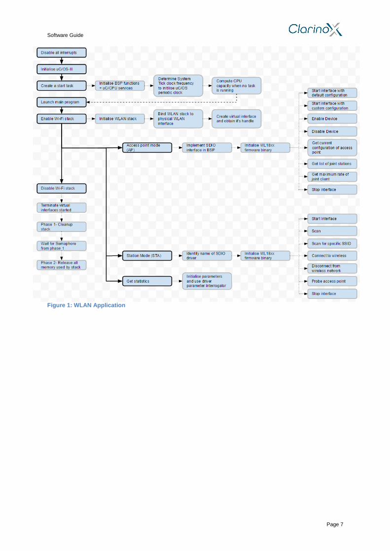
2.1 WLAN Application
The following project demonstrates basic Wi-Fi functionality with the option of acting as an access point or a station
1. Disable all interrupts 2. Initialise uC/OS-III 3. Create a start task with the following properties-
Initialises Board Support Package (BSP) functions
Initialises uC/CPU services
Determines System tick clock frequency
Determine number of System tick increments required and initialise uC/OS periodic clock using this information
Initialise LCD
Setup GPIO pins for SRAM data lines
Setup GPIO pins for LCD control pins
Setup GPIO pins for FSMC interface (FSMC configuration– memory type: SRAM, data width: 16bit, write operation: enable, extended mode: enable, asynchronous wait: disable)
Write values to LCD registers and Clear the LCD to prepare for image
Compute CPU capacity with no task running if required
Launch main program 4. Main program responsibilities-
Create a stack object
Board Support Package (BSP) initialisation
Initialise LwIP stack
Initialise dynamic memory heap
Initialise memory pools
Set IP, Netmask and GW address as 0 if using DHCP. Set desired IP, Netmask and GW otherwise (Setup network parameters such as IP address, MAC address, Netmask and GW address in “main.h” file).
Add network interface to the LwIP stack
Register default network interface
Initialise console UI engine with option tree to allow user to interact with program 5. Main Program capabilities-
Enable Wi-Fi stack
Initialise WLAN stack
Bind WLAN stack to physical WLAN interface
Create a single virtual interface and get an handle that will start, stop and control the interface
Option to activate Access point feature
Initialise parent list object that holds all other configuration objects
Implement SDIO interface in the Board Support Package (BSP)
Initialise WL18xx firmware binary
Determine maximum transmission power used by WL18xx hardware (in dB)
Set frames to be captured as all frames except for beacons
Access point options- 1. Start interface with default configuration- initialise configuration array objects
of supported data rates, establish SSID and start virtual interface operation that provides service using given WLAN interface. Display MAC address if virtual interface has successfully started. Default configuration-
a. Frequency Bandwidth: 2.4 GHz b. Channel: 6 c. Hidden SSID: 0 d. Channel Type: No_HT e. Beacon Interval: 300 f. Maximum number of stations: 8 g. Encryption passkey: Secure string determined by user
h. Encryption Protocol: Temporal key integrity protocol i. Inactivity timeout: 300 (seconds)

Software Guide
Page 5
2. Start interface with custom configuration- Provide option to alter the following parameters with appropriate UI (start virtual interface operation after configuring following parameters)-
a. Supported rates: choice of IEEE 802.11abg, IEEE 802.11n, IEEE 802.11b or IEEE 802.11g
b. Authentication: Open system authentication (OSA), WEP, TKIP, CCMP or TKIP+CCMP
c. Channel d. SSID broadcast: option to disable/enable SSID broadcast
3. Enable Device- configure and set client inactivity timeout (3000 seconds) and then start WLAN role associated with the respective interface (RF transceiver powered on and stack informs network interface about activation of the link) .
4. Disable Device- Stop WLAN role associated with the respective interface by removing all client stations connected, powering off RF transceiver and informing network interface that the link is down
5. Get current configuration of Access point- list SSID, passkey, hidden/broadcast SSID, channel and encryption protocol
6. Get list of joint stations- provide a list of joint stations along with the respective MAC addresses
7. Get Maximum rate for a joint client 8. Stop interface
Option to activate Station Mode
Initialise parent list object that holds all other configuration objects
Recommended values by driver- 1. Maximum transmitter power: 15 dB 2. Maximum size of MAC frames: 2352 3. Request to send (RTS)/ Clear to send (CTS) threshold: 2353 4. Wireless protected setup: Disable
Set frames to be captured as all frames except for beacons
Initialise configuration array object to hold list of supported data rates
Identify name of SDIO driver
Initialise WL18xx firmware binary
Station mode features- 1. Start interface-
a. Enable WL18xx hardware first b. Initiate bus driver and prepare for communication with WLAN
controller c. Boot controller d. Load firmware onto controller e. Set initial configuration parameters f. Enable request role in controller g. Acknowledge successful setup of virtual interface by printing MAC
address onto LCD screen h. Determine and list firmware version of WL18xx controller i. Initialise channels for scan procedures (ensure local regulatory
domain is adhered to) j. Send list of channels to WLAN stack
2. Scan- a. Scan for Access Points (AP) and repeat this process based on user
preference (recommended repetitions: 1). Scan for all available networks in the area (that are operating on the specified channels) rather than specific SSID
b. Provide the list of networks found (Basic Service Sets) 3. Scan for a specific SSID-
a. Request for specific SSID b. Perform WLAN scan for all available Basic Service Sets (BSS) c. Match SSID with list of BSS and output result
4. Connect to wireless network a. Request for SSID to connect to b. Connection mode: Associate (no prior connection with BSS is
assumed) c. Authentication type: Pre-shared master key d. Provide options for encryption protocols: No encryption, WPA or
WPA2 e. Pass encryption protocol to security credential of wireless network f. Encryption related parameters initialisation value: 0

Software Guide
Page 6
g. Request encryption passkey/master key h. Connect to network based on connection profile provided (and print
result) 5. Disconnect from wireless network- by sending de-authentication and de-
association frames to access point 6. Probe the access point-
a. Destination of probe request: broadcast address b. Maximum number of probe request: 5 c. Time interval between consecutive probe requests: 1 beacon
interval d. Print BSS information if successful
7. Stop interface- terminate virtual interface and disable WL18xx hardware
Option to activate P2P mode1
Option to provide statistics
Initialise parameters (Maximum transmission rate, maximum kink transmission rate and current transmission rate) to the value 0.
Retrieve and print parameter results using driver parameter interrogator
Option to disable Wi-Fi stack
Virtual interfaces that have been started must first be stopped before disabling Wi-Fi stack
1. Terminate virtual interface 2. Disable WL18xx hardware 3. Close service handle 4. Empty joint station list
Terminate WLAN stack- 1. Phase 1-
a. clean up stack by disconnecting from remote services and dismiss internal tasks and state machines
b. Provide indication of successful clean up to allow process to proceed to phase 2 (i.e. release semaphore as function has access to shared resource)
c. Release semaphore 2. Phase 2-
a. Wait for semaphore from Phase 1 b. Delete objects, threads and timers c. Release all memory used by the stack
3. Print result
1 Coming soon
Software Guide
Page 7
Figure 1: WLAN Application
Software Guide
Page 8
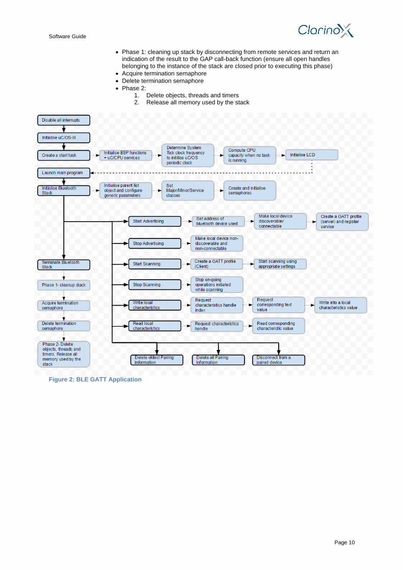
2.2 BLE GATT Application
The subsequent application demonstrates basic Bluetooth Low Energy functionality using the General Attribute Profile (GATT)
1. Disable all interrupts 2. Initialise uC/OS-III 3. Create a start task with the following properties-
Initialises Board Support Package (BSP) functions
Initialises uC/CPU services
Determines System tick clock frequency
Determine number of System tick increments required and initialise uC/OS periodic clock using this information
Initialise LCD
Setup GPIO pins for SRAM data lines
Setup GPIO pins for LCD control pins
Setup GPIO pins for FSMC interface (FSMC configuration– memory type: SRAM, data width: 16bit, write operation: enable, extended mode: enable, asynchronous wait: disable)
Write values to LCD registers and Clear the LCD to prepare for image
Compute CPU capacity with no task running if required
Launch main program 4. Main Program responsibilities-
Initialise BSP at applications level2
Assign user printf and scanf functions for overloading
Setup call-back function that is called during the initialisation of Bluetooth stack. This function is used to reset Bluetooth controller and download the firmware onto the controller using vendor specific HCI commands.
Initialise user interface engine and start menu to perform required operations based on user input
Determine input keyboard buffer size (recommended- 128) 5. Main program capabilities-
Initialise Bluetooth stack with parameters, event call-back functions, stack message handler and user exception handlers
Initialise parent list object that holds all other configuration objects 1. Transport type: UART (H4) 2. COM Port name: BLUETOOTH_PORT 3. COM Port Speed: 115200 4. Maximum number of paired devices: 4 5. Logic Link Control and Adaptation (L2CAP) outgoing buffer size: 512 6. L2CAP incoming buffer size: 512 7. L2CAP signal channel input container size: 256 8. L2CAP signal channel output container size: 256 9. L2CAP Maximum number of stack wide L2CAP connections: 8 10. L2CAP Signal channel Maximum Transmission Unit (MTU): 190 11. ATT channel Input container size: 512 12. ATT channel Output container size: 512 13. ATT channel maximum MTU: 300 14. ATT channel queued writes container size: 1024 15. HCI Driver incoming buffer size: 4096 16. HCI maximum number of outgoing commands in queue:5 17. RFCOMM incoming queue size: 512 18. RFCOMM outgoing queue size: 512 19. RFCOMM maximum number of L2CAP connections: 2 20. RFCOMM incoming MTU: 380 21. RFCOMM maximum outgoing data size: 380 22. SDP maximum number of L2CAP connections: 4 23. SDP incoming MTU: 48
Configure generic parameters 1. Support secure simple pairing: True 2. Enable link level authentication: False 3. I/O capabilities: Local device capable of displaying 6-digit decimal number
and allows user to provide YES/NO response to request 4. Link request timeout: 1600
2 Investigate

Software Guide
Page 9
5. Major class of device: Headset, Speaker, Stereo, Video display and VCR 6. Minor class of device: Car audio 7. Service classes-
a. Limited discoverable mode b. Positioning: location identification c. Networking: LAN, ad hoc d. Rendering: printing and speaker e. Capturing: scanner and microphone f. Object transfer: v_Inbox and v_Folder g. Audio: Speaker, microphone and headset service h. Telephone: Cordless telephony, modem and headset service i. Information: WEB server and WAP server
Initiates Bluetooth stack based on parameters defined and output result of operation
Release configuration parameters
Create a semaphores and initialise it (initial value: 0)
Start advertising
Set address of Bluetooth device used (type: Public- universally unique)
Make local device discoverable/connectable (start advertising) with the following settings-
1. Minimum advertising interval: 3000 2. Maximum advertising interval: 4000 3. Advertising type: connectable by anyone 4. Address Type: Public (universally unique) 5. Direct address (previously defined) 6. Advertising Filter policy: Scan and advertise connectable by anyone 7. Advertising data length: 32 8. Advertising data byte: length of assigned name + 2 9. Block type: False
Create a GATT profile with the following parameters: 1. Server: True 2. Create handle to instance of GATT profile used on server device with device
appearance set as generic display and stack message handler provided 3. Register a local service for the given Bluetooth Low energy GATT server
Stop Advertising- make device non-discoverable and non-connectable (block type: false)
Start scanning
Create a GATT profile with the following parameters: 1. Server: False 2. Create handle to instance of GATT profile used on the client device with
device appearance set as unknown and stack message handler provided
Start scanning with the following settings: 1. BLE scan type: Passive 2. BLE scan interval time between scans:100 3. BLE scan window duration: 80 4. Use whitelist: False 5. Block Type: False
Stop Scanning- by stopping any ongoing operation initiated when user requested device to start scanning (block type: False)
Write Local Characteristics- available to clients of this service when client notification/indication feature is set
Request characteristics handle index from user
Request text value for characteristic index
Initialise value of characteristic handle index by writing into a local characteristics value (block mode: True)
Read Local Characteristics- application reads characteristics value with writeable attribute
Request characteristics handle from user
Read from local characteristics value corresponding to user input
Print message
Delete oldest pairing information- delete pairing information of a specific paired remote device including bonded device (block mode: True).
Delete all pairing information- delete pairing information of all paired remote devices including bonded devices (block mode: True).
Disconnect from paired device
Terminate Bluetooth stack
Software Guide
Page 10
Phase 1: cleaning up stack by disconnecting from remote services and return an indication of the result to the GAP call-back function (ensure all open handles belonging to the instance of the stack are closed prior to executing this phase)
Acquire termination semaphore
Delete termination semaphore
Phase 2: 1. Delete objects, threads and timers 2. Release all memory used by the stack
Figure 2: BLE GATT Application

Software Guide
Page 11
2.3 SPP Application
The succeeding application presents basic Bluetooth classic functionality using the Serial Port Profile (SPP)
1. Disable all interrupts 2. Initialise uC/OS-III 3. Create a start task with the following properties-
Initialises Board Support Package (BSP) functions
Initialises uC/CPU services
Determines System tick clock frequency
Determine number of System tick increments required and initialise uC/OS periodic clock using this information
Initialise LCD
Setup GPIO pins for SRAM data lines
Setup GPIO pins for LCD control pins
Setup GPIO pins for FSMC interface (FSMC configuration– memory type: SRAM, data width: 16bit, write operation: enable, extended mode: enable, asynchronous wait: disable)
Write values to LCD registers and Clear the LCD to prepare for image
Compute CPU capacity with no task running if required
Launch main program 4. Main Program responsibilities-
Initialise BSP at applications level
Assign user printf and scanf functions for overloading
Setup call-back function that is called during the initialisation of Bluetooth stack. This function is used to reset Bluetooth controller and download the firmware onto the controller using vendor specific HCI commands.
Set device parameters used for advertising during an inquiry process
Major class of device: Desktop, Notebook, PDA and Organisers
Minor class of device: Desktop workstation
Service classes: v_Inbox and v_Folder
Enable link level authentication: False
I/O capabilities: Local device capable of displaying 6-digit decimal number and allows user to provide YES/NO response to request
Support secure simple pairing: True
Link request (paging) timeout: 60000
Initialise user interface engine and start menu to perform required operations based on user input
5. Main Program capabilities-
Initialise Bluetooth stack with parameters event call-back functions, stack message handler and the exception handler
Call-back in user thread- False
Block type: True
Create semaphores for connection and termination with initial value= 0 for both
Print result
Make device discoverable
Set device into discoverable mode (block mode: True)
Set device into connectable mode (block mode: True)
Print result
Make device non-discoverable
Set device into non-discoverable mode (block mode: False)
Print result
Search for devices in proximity and pair with selected device
Create SPP profile 1. Role: Client 2. Create a SPP handle with the following characteristics:
a. Universal unique identifier: NULL (standard Bluetooth SPP identifier)
b. Security requirement: Medium c. Provide a call-back function pointer
Start Inquiry process 1. Filtering: no filtering performed 2. Mode: General Inquiry mode 3. Start Inquiry from local device
a. Search for Bluetooth devices in vicinity

Software Guide
Page 12
b. Send indication through the call-back function if a Bluetooth device in the vicinity is found
c. Perform name request for each new device not already on the pairing list
4. Wait until a given number of devices are discovered or until a user prompt is entered
5. Stop inquiry to ensure Bluetooth radio is fully available for data transmission 6. List name of devices found along with universally unique Bluetooth address,
application assigned device ID, combination of generic services supported by device, major/minor class of device and RSSI value obtained by remote device during device discovery process
Pair devices 1. Request user for device to pair with for the list 2. Initiate bonding procedure with remote device 3. Ensure both local and remote devices are in bondable mode 4. Perform pairing by storing pairing information in a local storage area
Wait for incoming connection request
Create SPP profile 1. Role: Server 2. Create a SPP handle with the following characteristics:
a. Universal unique identifier: NULL (standard Bluetooth SPP identifier)
b. Security requirement: Medium c. Provide a call-back function pointer
Set Device into discoverable mode (block mode: True)
Wait for connection (by acquiring a connection semaphore)
Connect to a paired Device
Create SPP profile 1. Role: Client 2. Create a SPP handle with the following characteristics:
a. Universal unique identifier: NULL (standard Bluetooth SPP identifier)
b. Security requirement: Medium c. Provide a call-back function pointer
Print a list of paired devices along with their details
Request the user for the device to connect to
Connected device options- 1. Connect to SPP1
a. Discover COM ports on the remote device b. Connect to a port if a suitable SDP port is found using parameters
retrieved via SDP operation. Set device into non-connectible and non-discoverable mode
c. Start receiving data from remote client (receiver buffer size:333 2. Send Text
a. Request user for data to transmit b. Write data onto a buffer c. Start sending data to remote server
3. Disconnect from SPP1 (disconnect from remote virtual serial connection) 4. Hard Reset- perform procedure from “Wait for incoming connection request”
in main function
Delete oldest pairing information- delete pairing information of a specific paired remote device including bonded device information from persistent storage (block mode: True).
Delete all pairing information- delete pairing information of all paired remote devices including bonded devices information from persistent storage (block mode: True).
Terminate Bluetooth stack
Delete SPP profile handle as there is no user for this profile any longer (close SPP handle)
Phase 1: cleaning up stack by disconnecting from remote services and return an indication of the result to the GAP call-back function (ensure all open handles belonging to the instance of the stack are closed prior to executing this phase)
Acquire termination semaphore
Delete termination semaphore
Delete connection semaphore
Phase 2: 1. Delete objects, threads and timers 2. Release all memory used by the stack

Software Guide
Page 13
Figure 3: SPP Application

Software Guide
Page 14
2.4 USART printf Demo
This application achieves Serial communication over the USART to USB Bridge
1. Configure the USART
Setup GPIO pins to connect USART to USB bridge
Enable GPIO Clock
Setup USART peripheral (typical settings: 921600 baud, 8 Bits, One Stop Bit, No parity, No flow control receive and transmit enabled)
Enable USART 2. Print a message to the terminal to confirm setup
Redirect printf output to USART transmit
Write each character of the message to the USART
Wait until transmission finishes 3. Check if a character is received; If no character is received, keep
checking until a character is received 4. When a character is received, read the character and repeat step 5 to
display the character back on terminal 5. Return to step 3
Table 1: USART Project Directory
Type File Description
Source Files system_stm32f4xx.c STM32F4xx System clock configuration file
stm32f4xx_it.c Interrupt handlers main.c Main program
Header Files stm32f4xx_conf.h Library configuration file stm32f4xx_it.h Interrupt handlers header file main.h Main program header file
2.5 LCD Demo
This application displays a Clarinox logo on the LCD screen
1. Initialise System Tick timer and the corresponding interrupt 2. Initialise LCD
Setup GPIO pins SRAM data lines
Setup GPIO pins for LCD control pins
Setup GPIO pins for FSMC interface (FSMC configuration– memory type: SRAM, data width: 16bit, write operation: enable, extended mode: enable, asynchronous wait: disable)
3. Write values to LCD registers and Clear the LCD to prepare for image 4. Set LCD screen window and resolution along with text settings (font and
colour) 5. Write main content onto LCD (BMP image data constituting the Clarinox
logo) along with header and footer
Figure 4- USART printf
Figure 5: LCD Demo

Software Guide
Page 15
2.6 LCD Touch Screen
Precise coordinates of contact on LCD touch screen are determined and displayed back on the LCD screen by the following application
1. Initialise System Tick timer and corresponding interrupt 2. Initialise LCD
Setup GPIO pins for SRAM data lines
Setup GPIO pins for LCD control pins
Setup GPIO pins for FSMC interface (FSMC configuration– memory type: SRAM, data width: 16bit, write operation: enable, extended mode: enable, asynchronous wait: disable)
Write values to LCD registers and Clear the LCD to prepare for image
3. Configure SPI, to read from touch sensor 4. Calibrate touch screen
1. Ask user to touch 3 points with known coordinates 2. Record read values 3. Generate calibration matrix
5. Wait until touch detected 1. Read coordinates in samples of 20 and take
average, apply calibration matrix 2. Draw dot to represent coordinates point of contact
2.7 Camera Demo (DCMI)
This example demonstrates interfacing an OV9655 camera over the DCMI and using it to capture images which are displayed on an LCD 1. Camera Clock Setup
Configure phase lock loop (PLL) clock by disabling default clock configuration
Set up GPIO pin for MCO1
Use PLL to generate output clock to this pin
Re-enable system clock using PLL 2. Initialise System Tick timer and corresponding interrupt 3. Initialise LCD
Set up GPIO pins for LCD control pins
Set up GPIO pins for FSMC interface (FSMC configuration– memory type: SRAM, data width: 16bit, write operation: enable, extended mode: enable, asynchronous wait: disable)
Write values to LCD registers and Clear the LCD to prepare for image 4. Camera configuration
Initialize DCMI interface using GPIO pins for I2C
Read manufacturers ID from camera using I2C
Select image format (e.g. QVGA, JPEG, etc.)
Configure DCMI- capture mode: continuous, Synchronisation mode: hardware, PCK polarity: high, HS/VS polarity: high, capture rate: capture all frames, data width: 8bit)
Configure DMA2 to transfer data from DCMI
Enable DMA2 clock
Stream:1, Channel:1
Peripheral base address: DCMI address
Memory base address: Image buffer address (FMSC)
Data transfer: Peripheral to memory
Figure 6: LCD Touch

Software Guide
Page 16
Buffer size: 9600 for formats other than JPEG (3000 for JPEG)
Incrementing peripheral address memory: Disable
Incrementing memory address register: Enable
Peripheral data width: word, Memory data width: half word
DMA mode: circular
FIFO- enabled, threshold: full
Memory burst: single, Peripheral burst: Single
Configure DMA 2 interrupt request (IRQ) channel
Enable DMA2 stream 1 and DCMI interface passed on image format
Enable and configure interrupts relating to DCMI: end of frame, overflow and error interrupts
Write camera registers for selected image format using I2C
This Example used BMP_QQVGA (160x120 rgb565)
Enable the DCMI 5. Capture images
DCMI capture enable
Set LCD screen window and resolution
Wait for image buffer array to fill from DMA
Scan through each element of array and write value to LCD at designated pixel
Draw each row until image is complete using LCD coordinates
Each pixel is displayed on four adjacent pictures on LCD screen to fill screen
Clear DMA and DCMI flags and wait for next frame
2.8 CAN Bus Demo
This application demonstrates transmitting a character over CAN and receiving it on another board
1. Set up interrupts for CAN received (NVIC configuration) 2. CAN Configuration
Set up CAN RX and TX GPIO pins
Set up CAN parameters
Enable CAN clock
Initialise CAN register
Trigger communication mode: Disable
Automatic bus-off management: Disable
Automatic wake up mode: Disable
Non-automatic retransmission mode: Disable
Receive FIFO locked mode: Disable
Transmit FIFO priority: Disable
CAN operating mode: Normal
Length of time quantum: 15
Time quanta allowed: 1
Time quanta in bit segment 1: 13
Time quanta in bit segment 2: 2
Initialise CAN structure using 125KHz baud
Initialise Can Filter
Mode: ID mask
Scale: 32 bit
High: 0x0000, Low: 0x0000
Figure 7: Camera Demo

Software Guide
Page 17
Mask ID High: 0x0000, Mask ID Low: 0x0000
FIFO assignment: 0
Filter activation: Enable
Prepare Transmit structure
Standard Identifier: 0x321
Extended Identifier: 0x01
Identifier message: Standard
Message frame: Data
Frame Length: 1
Enable message pending interrupt 3. Initialise LCD
Set up GPIO pins for LCD control pins
Set up GPIO pins for FSMC interface (FSMC configuration– memory type: SRAM, data width: 16bit, write operation: enable, extended mode: enable, asynchronous wait: disable)
Write values to LCD registers and Clear the LCD to prepare for image 4. Transmit a message to the bus if Sender (e.g. message- CAN) 5. Interrupt Service Routine when a message is received
Check message ID and put into a buffer
Read message from buffer and display message on the LCD
Send an arbitrary reply acknowledging message (e.g. Reply)
Figure 8: CAN Bus Demo
Software Guide
Page 18
2.9 Ethernet and Stack
This example is based on the IAP example from STMicroelectronics, but has been configured to run on the EVM board. This program demonstrates connection to an Ethernet network and running TCP/IP using the LWIP protocol stack. 1. Initialise LCD
Set up GPIO pins for LCD control pins
Set up GPIO pins for FSMC interface (FSMC configuration– memory type: SRAM, data width: 16bit, write operation: enable, extended mode: enable, asynchronous wait: disable)
Write values to LCD registers and Clear the LCD to prepare for image 2. Configure Ethernet using board support package (BSP)
Configure network settings (e.g. IP address, MAC, Gateway, etc.) in the “main.h” file if required
Configure GPIO ports for Ethernet pins
Configure Ethernet MAC/DMA
Enable Ethernet clock
Reset Ethernet on AHB bus and perform a software reset
Ethernet parameters (MAC): 1. Auto Negotiation: Disable 2. Speed: 10M 3. Mode: Full Duplex 4. Loopback mode: Disable 5. Retry transmission: Disable 6. Automatic MAC Pad/CRC stripping: Disable 7. Receive all: Disable 8. Broadcast frame reception: Enable 9. Promiscuous mode: Disable 10. Multicast frames filter: Perfect 11. Unicast frames filter: Perfect 12. Checksum Offload: Enabled if checksum by hardware is true
Ethernet parameters (DMA): 1. Drop TCP/IP checksum error frame: Enable 2. Receive, store and forward mode: Enable 3. Transmit, store and forward mode: Enable 4. Forward error frames: Disable 5. Forward undersized good frames: Disable 6. Second frame operate: Enable 7. Address aligned beats : Enable 8. Fixed burst: Enable 9. Receiver DMA burst length: 32 beats 10. Transmitter DMA burst length: 32 beats 11. DMA arbitration: Round robin receiver/transmitter 2-1
3
Configure Physical Layer to generate an interrupt on change of link status
Read MICR register
Enable output interrupt events to signal
Read MISR register
Enable interrupt on change of link status
Configure EXTI4 for Ethernet link status
Enable INT clock
Configure INT pin as a GPIO input pint
Connect EXTI line to INT pin
Configure EXTI line 1. Line: Enable 2. Mode: Interrupt 3. Trigger: Falling 4. Line command: Enable
Enable and set the EXTI interrupt as the highest priority
Configure system clock source as HCLK (processor clock)
Setup System tick to provide interrupt every 10 millisecond 3. Initialise LwIP stack
Initialise dynamic memory heap
Initialise memory pools
3 Check for precise definition of rxtx_1_2
4 Check for full forms of EXTI and INT

Software Guide
Page 19
Set IP, Netmask and Gateway address as 0 if using DHCP. Set desired IP, Netmask and Gateway otherwise.
Add network interface to the LwIP stack
Register default network interface
Activate the interface, allowing it to be available for processing traffic 4. If using HTTP, initialise web server module. If using TFTP server, initialise TFTP server
5
Web server module initialisation
Create new protocol control block (PCB)
Bind HTTP traffic to PCB
Start listening on PCB port (port 80)
Define call-back function for TCP connection setup 5. Check if any packet received (in a polling loop)
If the process received an Ethernet packet, read the received packet from the Ethernet buffers and send it to the LwIP packet handler
Determine type of packet and forward it to the appropriate function to process it 6. Periodic tasks (if no packet, run these tasks)
Run TCP timer after a discrete interval
Run ARP update after a discrete interval
Run DHCP process after a discrete interval
Run DHCP coarse process after a discrete interval
5 No reference for this present in code
Figure 9: Ethernet and Stack

Software Guide
Page 20
2.10 USB Host and Device
USB Device program simulates a Human interface device (HID) mouse and moves the cursor on a computer screen in response to detection of touch on LCD screen.
1. Initialise System Tick timer and corresponding interrupt 2. Initialise LCD
Set up GPIO pins for LCD control pins
Set up GPIO pins for FSMC interface (FSMC configuration– memory type: SRAM, data width: 16bit, write operation: enable, extended mode: enable, asynchronous wait: disable)
Write values to LCD registers and Clear the LCD to prepare for image
Display instructions on screen 3. Initialise device stack and load the class driver
Initialise hardware
USB OTG is used in Full Speed (FS) mode
Setup GPIO pins 1. Speed: 100MHz 2. Mode: Alternate function mode 3. Operating output type: push/pull 4. Operating pull-up/ pull down: no
Enable OTG peripheral clock
Initialise delay unit using a separate timer interrupt
Re-initialise device library
Register class and user call-backs
Setup USB OTG core parameters
Initialise core register addresses
Initialise core
Force mode to Device Mode
Initialise device
Enable USB global interrupt
After initialisation, call user call-back
Configure USB global interrupt 4. Wait for touch input and perform interrupt service routine
Figure 10: USB Host and Device
Software Guide
Page 21
3 WMI Debugging Applications Since separate WMI modules include their own microcontroller, they can be programmed independently and the EVM board can be configured as a bridge between the module and external devices. This would allow access to serial (USART) information from the WMI module over USB or Ethernet.
3.1 USART Bridge
This application sends characters from the WMI module to the STM32F429/ STM32F407 for retransmission to the USB serial port.
1. The software procedures for this project are similar to USART printf demo application with the exception of characters received from USART3/USART2 will be sent to USART1 and vice versa
2. The application is available in two modes:
Interrupt mode
DMA modes
3.2 Ethernet to USART
The following program listens for data received over the Ethernet socket and writes it on to the USART peripheral in single characters. In addition it can send characters form the WMI module to the network interface to make them available to read on another device
1. Configure USART 2. The remaining software procedures for this project are similar to Ethernet and stack demo application
with the exception of HTTP server and LCD interface being absent

Software Guide
Page 22
4 Additional Information
4.1 Compiling
When compiling the provided applications with Keil MDK, the “--c99” flag must be set in compiler options.
For stability and performance reasons, IAR is recommended over Keil MDK
Each application has configurations for both variants of the Koala EVM (STM32F407IG and STM32F429II); this can be selected in the project file before building.
4.2 Application Specific Notes
4.2.1 Data Speeds Baud rate generation may depend on system clock configuration
For application stability, It is recommended not to exceed specified data transfer rates
4.2.2 USB USB application may sometimes require full erase of microcontroller chip before programming. This can
be achieved through the STM32 ST-Link Utility
Due to differences in formats of binary flash files, it is best to confirm operation of the USB Host with a USB analyser
USB micro adapter may be required for some devices when using USB host mode
4.2.3 Camera Large resolution image capture may not be possible due to memory constraint and lack of compression
in supported camera OV9655
Some camera variants require a clock signal (XCLK). The microcontroller’s PLL and MCO can be used for this purpose. In addition, a 24MHz clock has been provided for this purpose aswell.
4.2.4 Ethernet By default the application is configured with a static IP address. DHCP and network settings can be
configured in the “main.h” header file.
4.2.5 CAN Bus High and low signal lines must be matched on each device and connected via on board screw terminals
Line termination is required for high speed or long distance operation.
4.2.6 UART Bridge PC may require a software driver for the USB-UART peripheral
Observe jumper configuration if using USART2 for WMI modules. See readme files of each application for further details.
4.3 Memory Requirements
The table below provides approximate memory and flash usage of the applications
Name Binary (KB) Memory (bytes)
LCD 23 24308
CAN (receive) 17 19104
CAN (send) 14 15436
DCMI 24 64873
LCD Touch 25 27160
USART printf 6 7681
Ethernet stack 41 64769
USB device 12 14689
USB HOST (FW demo) 19 64815
USART bridge* 4 4294
USART to Eth* 34 68881
Table 2: Memory and flash requirements of each application
*Details current as of 10/2/2014, actual requirements may change.


![Chapter 7 Input and Outputoz.nthu.edu.tw/~d947207/chap7.pdf · Formatted output – printf [1] ... Formatted input – scanf int scanf ( char *fmt, ... ) int fscanf ( FILE* stream,](https://img.dokumen.tips/doc/110x75/5ec75aeb1ef01d61b2538660/chapter-7-input-and-d947207chap7pdf-formatted-output-a-printf-1-formatted.jpg)