Embed Size (px)
Citation preview

Knowledge Projection System System Design Specification
Document
Version 3.0
7/5/2005 8:42:00 AM Purdue University
Knowledge Project System
SDSD Page 2 of 58 5/16/2006
Approvals Stakeholder Name Organization & Role Signature Date
David Bartlett Crane – Project Manager
Mark Boike Crane – Deputy Project Manager
William Brenner EG&G – Project Manager
Lisa Sturgeon EG&G - Technical Integrator
Rick McMullen IU – Project Manager
Chris Clifton Purdue – Project Manager Document Change Control Revision Number Date of Issue Author(s) Brief Description of Change 12/15/2004 Mourad Ouzzani and Anne C.
Catlin Second version of the system design specification document

Knowledge Project System
SDSD Page 3 of 58 5/16/2006
Table of Contents
Introduction..................................................................................................................................... 6 1. Document Overview ............................................................................................................... 6
1.1. Document Purpose .......................................................................................................... 6 1.2. Document Scope ............................................................................................................. 6 1.3. References....................................................................................................................... 6 1.4. Software Design Specification Document Development Guidance ............................... 6 1.5. Terminology.................................................................................................................... 6
2. KPS Architecture Overview ................................................................................................... 6 3. Knowledge base schema......................................................................................................... 7
3.1. XML Schemas ................................................................................................................ 7 3.1.1. Process (Process.xsd).............................................................................................. 8 3.1.2. Document (Document.xsd) ................................................................................... 14 3.1.3. Figures (Figure.xsd).............................................................................................. 15 3.1.4. Smart Tables (TableDef.xsd, TableInst.xsd, TableRow.xsd) ............................... 17 3.1.5. Smart Images (smartImage.xsd) ........................................................................... 21 3.1.6. Sessions (FaultSession.xsd) .................................................................................. 24 3.1.7. SchemaLib.xsd...................................................................................................... 27 3.1.8. Supporting Data (Link.xsd) .................................................................................. 28
3.2. XML Tables .................................................................................................................. 28 3.2.1. Summary XML Schemas, Documents, and Tables .............................................. 28
3.3. Relational Tables .......................................................................................................... 29 3.3.1. Dynamic Maintenance .......................................................................................... 29
3.3.1.1. Table Load_SourceSRA ............................................................................... 30 3.3.1.2. Table EventLinks .......................................................................................... 30 3.3.1.3. Table NextEvent ........................................................................................... 31 3.3.1.4. Table SystemStartScenario ........................................................................... 31 3.3.1.5. Table SystemNextScenario........................................................................... 31 3.3.1.6. Table DatabaseCalls...................................................................................... 31 3.3.1.7. Table DatabaseCallParameters ..................................................................... 32 3.3.1.8. Table Notes ................................................................................................... 32 3.3.1.9. Table EventsAfterNotes................................................................................ 32 3.3.1.10. Table Warnings............................................................................................. 33 3.3.1.11. Table SpecialProcedures............................................................................... 33 3.3.1.12. Table GeneralNotes ...................................................................................... 33 3.3.1.13. Table Synchronization .................................................................................. 33
3.3.2. Data Mining .......................................................................................................... 34 3.3.2.1. Table FaultSession ........................................................................................ 35 3.3.2.2. Table Action.................................................................................................. 35 3.3.2.3. Table Action_Parameter ............................................................................... 35 3.3.2.4. Table Action_Link ........................................................................................ 35 3.3.2.5. Table Event_Node ........................................................................................ 35 3.3.2.6. Table Node_Link .......................................................................................... 35 3.3.2.7. Table Current_Node...................................................................................... 35 3.3.2.8. Table Part ...................................................................................................... 35 3.3.2.9. Table Part_Ship............................................................................................. 35 3.3.2.10. Table Part_Fault_Ship .................................................................................. 35

Knowledge Project System
SDSD Page 4 of 58 5/16/2006
3.3.2.11. Table Ship_Class .......................................................................................... 35 3.3.2.12. Table Ship ..................................................................................................... 35 3.3.2.13. Table Part_Fault............................................................................................ 35 3.3.2.14. Table Fault .................................................................................................... 35 3.3.2.15. Table Part_Log_Ship .................................................................................... 35
3.4. XML document transformation and presentation ......................................................... 35 3.5. Dynamic Maintenance Functions and Procedures........................................................ 35
3.5.1. Supporting PL/SQL Functions.............................................................................. 35 3.5.2. Parse Process PL/SQL Functions.......................................................................... 35 3.5.3. Session PL/SQL Functions ................................................................................... 35
3.6. Data Mining Functions and Procedures........................................................................ 35 3.6.1. Supporting PL/SQL Functions.............................................................................. 35 3.6.2. Java Stored Procedures ......................................................................................... 35
4. Application Infrastructure..................................................................................................... 35 4.1. Knowledge Projection Portal ........................................................................................ 35
4.1.1. ShipLogin.jsp ........................................................................................................ 35 4.1.2. SoreLogin.jsp ........................................................................................................ 35 4.1.3. MainMenu.jsp ....................................................................................................... 35 4.1.4. TSSControl.jsp...................................................................................................... 35 4.1.5. StartTSS.jsp .......................................................................................................... 35 4.1.6. Maintainer.jsp ....................................................................................................... 35
4.1.6.1. Execute.jsp .................................................................................................... 35 4.1.6.2. flowchart.jsp.................................................................................................. 35 4.1.6.3. bottom.jsp...................................................................................................... 35
4.1.7. TextSession.jsp: .................................................................................................... 35 4.2. Client Side..................................................................................................................... 35
4.2.1. CraneQuery.java ................................................................................................... 35 4.2.2. StoredProcedureCall.java...................................................................................... 35 4.2.3. Action.java, Chart.java ......................................................................................... 35 4.2.4. SaveTextSession.java............................................................................................ 35 4.2.5. TextSessionSupport.java:...................................................................................... 35
4.3. Troubleshooting Processing.......................................................................................... 35 4.3.1. Knowledge Projection Control ............................................................................. 35 4.3.2. Trouble Shooting Session Processing................................................................... 35 4.3.3. Parse Process......................................................................................................... 35 4.3.4. Fault Session Capture ........................................................................................... 35 4.3.5. SaveTextSession.java............................................................................................ 35
4.4. Data Mining Processing................................................................................................ 35 5. System Features .................................................................................................................... 35
5.1. Login ............................................................................................................................. 35 5.2. The Fault Session component ....................................................................................... 35 5.3. Text Session component ............................................................................................... 35 5.4. TSS Status control component...................................................................................... 35 5.5. Ship Side Linkage Infrastructure Ship Side Linkage Infrastructure for Maintainer Submitted Files ......................................................................................................................... 35 5.6. Ship Side Linkage Infrastructure for SME Submitted Files ......................................... 35 5.7. Shore Side Linkage Infrastructure for both SME and Maintainer Submitted Files...... 35 5.8. Ship Side Linkage Infrastructure for SME Submitted File Get New files Component 35

Knowledge Project System
SDSD Page 5 of 58 5/16/2006
5.9. Parse Process................................................................................................................. 35 5.10. SaveSession............................................................................................................... 35 5.11. Text Block Enhancement to TSS Sessions ............................................................... 35 5.12. User Interface Improvement for Session Viewer...................................................... 35 5.13. Data Mining .............................................................................................................. 35 5.14. Troubleshooting Session........................................................................................... 35
5.14.1. TSS Start Component ........................................................................................... 35 5.14.2. TSS Append Component ...................................................................................... 35 5.14.3. TSS Submit to Ship KPS Component................................................................... 35 5.14.4. TSS Send to Shore Component............................................................................. 35 5.14.5. TSS Receive All Files on Ship Component.......................................................... 35 5.14.6. TSS Receive All Files on Shore Component........................................................ 35
5.15. Scenario Viewer........................................................................................................ 35 5.16. Troubleshooting Session Viewer .............................................................................. 35
Table of Figures
Figure 1 KPS Infrastructure: Data & Code..................................................................................... 7 Figure 2 Technical Manual Process Specification for SLQ-32 HVS Subtest 1 TDFD.................. 8 Figure 3 Process XSD with the Scenario element. ....................................................................... 10 Figure 4 Action Block................................................................................................................... 11 Figure 5 Condition Block.............................................................................................................. 12 Figure 6 Document XSD .............................................................................................................. 14 Figure 7 The Figure XSD ............................................................................................................. 16 Figure 8 The Table Definition XSD ............................................................................................. 17 Figure 9 The tableInstance XSD................................................................................................... 19 Figure 10 The TableRow XSD ..................................................................................................... 20 Figure 11 The smartImage XSD................................................................................................... 22 Figure 12 Shape block (smartImage XSD): Supports the “Use Map” web browser concept....... 22 Figure 13 The FaultSession XSD ................................................................................................. 25 Figure 14 KPS Data Flow and Control ......................................................................................... 35 Figure 15 Online Trouble Shooting .............................................................................................. 35

Knowledge Project System
SDSD Page 6 of 58 5/16/2006
Introduction The Knowledge Projection System (KPS) project is an applied research project aimed at developing technologies for improving the use of systems knowledge to efficiently provide a more cost-effective approach for maintenance operations on Navy vessels. The KPS is to provide the fleet with web-based troubleshooting capabilities, access to mined data from traditional and non-traditional data sources, case based reasoning to subject matter experts, recommendations for maintenance process improvements in the areas of technical manuals, training, test direction flow, or logistics.
1. Document Overview 1.1. Document Purpose Define how the application or system should work, including the proposed components and what they will do. This also includes database design for relational and XML data.
1.2. Document Scope This document describes the detailed architectural design for the system. It specifies all known components needed to deliver the complete Knowledge Projection System.
1.3. References • CBR Design Specification Document • HPKB Design Specification Document • Data Mining Design Specification Document • Non-Traditional Data Design Specification Document • HMI Design Specification Document • System Integration Design Specification Document
1.4. Software Design Specification Document Development Guidance • IEEE Std. 1016-1998 IEEE Recommended Practice for Software Design Descriptions
1.5. Terminology
2. KPS Architecture Overview Figure 1 KPS Infrastructure: Data & Codeis a high level description of the Knowledge Projection System. The infrastructure’s major component is the Oracle XML Knowledge Base. This knowledge base hosts all the data and most of the code of the infrastructure.

Knowledge Project System
SDSD Page 7 of 58 5/16/2006
Figure 1 KPS Infrastructure: Data & Code
3. Knowledge base schema The Purdue XML knowledge base supports scenario-based knowledge projection for dynamic shipboard troubleshooting. In this section, we detail the different metadata components that make up the knowledge base.
3.1. XML Schemas The XML Knowledge Base supports scenario-based knowledge projection for dynamic shipboard troubleshooting. The objective is to give the sailor who is troubleshooting a system fault report “all the information he needs, exactly when he needs it.”
We have defined a number of fault-specific troubleshooting scenarios for the SLQ-32 High Voltage Sequencer Unit and Display Control Console. The XML information to support these scenarios includes:
• TDFD/TDD process • Associated documents and figures • Required table and component information.
In the XML KB, smartTables and smartImages are represented as non-traditional data types, with content-specific storage, access, search and presentation. Other non-traditional types, such as email, chat room and SME hotline support, are being added as we progress in the project.
All troubleshooting information is represented as XML documents in the Knowledge Base. In this section, we detail the different XML schemas upon which these documents are built. The following XML schemas are the core schemas required to support dynamic troubleshooting:
(1) Process (including internal process support structures for dynamic event processing) (2) Documents (3) Figures
Oracle 9i XML Knowledge Base
KPS Application Server Oracle 9i AS J2EE oc4j for web-based client interface
JSP Applet Java
• JDBC connection • XML message communication • SQL data query
from client to Oracle 9i database
• XML/XSL or HTML for client display • XML message communication • SQL data retrieval
from Oracle 9i database to client
XSD, XML, XSL
Supporting Relational Tables
PL/SQL Functions and Scripts
Java Stored Procedures
Data Layers
Code Layers

Knowledge Project System
SDSD Page 8 of 58 5/16/2006
(4) smartTables (5) smartImages (6) FaultSession (7) Supporting data structure
XML schema design adheres to the following general guidelines and standards:
• Schema representations include a block of keyword elements for indexing and searching.
• There is a standard format for linking related elements that is used across all schema representations. For example, events in the Process schema (describing the process event flow) will contain links to elements in Documents, Figures, smartTables, and smartImages, as needed to fully support the given step in the troubleshooting process.
• All schema representations identify the technical manual and revision from which the information (for tables, figures, images, components, etc.) was extracted.
To represent the knowledge required for our scenario-based troubleshooting KB, we define eight XMLType database tables with their associated XSDs. At least one XSL is needed for each schema to support Web browser display and operation. The schema also includes other supporting data structures that will be accessed during the dynamic maintenance process, session generation and off line data mining for retrieving further information.
3.1.1. Process (Process.xsd) The Process XML schema identifies all possible activity paths through the TDFD/TDD as a series of events. It is designed based on technical manual process specification as depicted in Figure 2.
Figure 2 Technical Manual Process Specification for SLQ-32 HVS Subtest 1 TDFD
Process XML Schema (Figure 3) is the fundamental unit for the XML representation of troubleshooting procedures. It has the following properties:
(1) Allows to present an online interface to troubleshooting procedures through the use of XSL transformations
(2) Follows codified procedures step-by-step

Knowledge Project System
SDSD Page 9 of 58 5/16/2006
(3) Handles any form of special procedures by incorporating them directly into the standard flow
(4) Automatically retrieves technical manuals, diagrams, tables at each step from clickable links
(5) Presents information links in order of usefulness and supports search of knowledge base (6) Visualizes diagnostic flow path as dynamically constructed flowchart
The Event Links block allows external content to be attached to the Event step. The Links to be associated with a given step are determined by a database call. Each event is defined as being one of the following items:
1. An action which identifies either a specific next event or information gathered from a process. Information gathering may require input from the sailor or extraction of data from supporting internal data structures.
2. A condition with a Boolean evaluation that is based either on the execution of a database function or input from the sailor.
The Process XML schema is responsible for generating session data, including capture of measurements and other relevant information. The Process will also access data mining knowledge associated with the current event. The corresponding XSL is used to display the Process XML dynamically in a Web browser, with all necessary linkage to content required for active decision-making. Our linked content consists of Documents, Figures, smartTables, smartImages and Components.
There is a single XMLType database table and validating XSD for the Process. There are five kinds of XML documents that comply with the Process XML schema:
1. General Scenario for High Voltage and Relay Control: This is the troubleshooting scenario start up to initiate fault specific scenarios (contained in ScenarioS0.xml)
2. High Voltage and Relay Control - Subtest 1: Test Direction Flow Diagram for SLQ-32 High Voltage Section Subtest 1 (contained in ScenarioS1.xml)
3. SME Scenarios (contained in ScenarioSME1.xml, ScenarioSME2.xml, and ScenarioSME3.xml)
4. Specific notes for some faults (contained in ScenarioSN<faultNumber>_<sequence>.xml): special notes are sequences of steps that are associated with fault table elements (like the signals in the signal table associated with a fault). The 'special notes' sequence of steps may occur over and over again as the main scenario moves down the series of table elements. In fact, special notes also branch off and come back to the main scenario, but they are associated with a recurring set of table elements.
5. Specific procedures for some faults (contained in ScenarioSP_<FaultNumber>.xml): special procedures are independent sequences of steps that branch off the main scenario (ScenarioS1) and come back. The special procedure is triggered at a given step and then returns to the main scenario.
The Action and Condition Blocks of the Process XSD lay out the guided steps from the flowchart. Each step is either an action (with a single target for the “next step”) or a condition (with a yes/no decision-based target for the “next step”.) Any action or decision target can be determined in the most general case by a database call.

Knowledge Project System
SDSD Page 10 of 58 5/16/2006
Figure 3 Process XSD with the Scenario element.
More specifically, the schema defines one single element scenario (Figure 3). This element has one attribute ID that gives a unique identifier in the system and the following elements1:
1. ClassInfo (String): Specifies the classification of target system to be maintained, it is “SLQ32-HVS” for all documents.
2. Name (String): The name of the scenario. 3. Description (String): Textual description of the scenario. 4. Type (String): Specifies the type of the scenario which could be Generic, Specific, SME,
or Special Procedure. 5. Link (LinkType): Link to external documents. 6. SystemID (String): Specifies the target system ID to be maintained, it is “SLQ32” for all
documents.
1 The type is specified between parentheses.

Knowledge Project System
SDSD Page 11 of 58 5/16/2006
7. SubSystemID (String): Specifies the sub-system ID being targeted, it is “HVS” for all documents.
8. StartEvent (String), and EndEvent (String): Give the range of event ID contained in this scenario.
9. Sequence of Event: Is the main element that determines step by step how a troubleshooting and maintenance scenario is conducted.
Event is defined by one attribute ID (unique identifier) and the following elements: 1. Name (String): Name of the event. 2. DetailedScenario (String), 3. Caution (String): Textual message warning about eventual cautions to take when
conducting the action related to this event. 4. Links (sequence of DatabaseCall (SchemaLib:DatabaseCallType)): 5. Textnotes (sequence of DatabaseCall (SchemaLib:DatabaseCallType)) 6. A choice between Condition and Action: An event is basically either a condition to test or
an action to do.
Action (Figure 4) is defined by a sequence of the following elements: 1. A choice between two elements DatabaseCall (SchemaLib:DatabaseCallType) and Input
(SchemaLib:InputType) 2. NextEvent (NextEventType) 3. SkipToEvent (NextEventType) 4. PreviousEvent (NextEventType)
Figure 4 Action Block
Condition (Figure 5) is defined by a sequence of the following elements: 1. Input (SchemaLib:InputType): Specifies how to get the condition (Boolean) to guide the
next event to execute. 2. NextYESEvent (NextEventType): Specifies the next event if the condition is true.
NextEventType is a sequence of DatabaseCall (SchemaLib:DatabaseCallType). 3. NextNOEvent (NextEventType): Specifies the next event if the condition is false.

Knowledge Project System
SDSD Page 12 of 58 5/16/2006
4. PreviousEvent (NextEventType): Specifies the event that precedes the current one.
Figure 5 Condition Block
Here is an excerpt of XML data that complies with this schema highlighting the case of a Condition event. This event is about running the SDT and checking that whether the fault reporting has changed. It requests a user entry to the question “SDT fault reporting changed?” and then do a database call (DatabaseCall) to retrieve (DataRetrieval) the next event (by calling the function GetNextEvent or GetNextNoEvent) to execute based on the user reply (Yes or No respectively). It also specifies how the get the previous event using a database call (DatabaseCall) to retrieve (DataRetrieval) it (by calling the function GetPreviousEvent). In some cases, those events are directly provided in the XML document without accessing the database. The element Links specifies how to get all XML documents (XMLList) related to this event, again using a database call (DatabaseCall) to retrieve (DataRetrieval) them.

Knowledge Project System
SDSD Page 13 of 58 5/16/2006
Here is an excerpt of XML data that complies with this schema highlighting the case of an Action event. This event means that we need to swap the interchangeable SRUs. It first specifies that the sailor need to be cautious in doing so Caution. The event consist in a database call (DatabaseCall) to retrieve (DataRetrieval) the interchangeable SRUs by calling the function (DisplayInterchangeableSRU). It also specifies that E5 is the next event, E3 is the event to skip to, and E3 is the previous event. The element Links specifies how to get all XML documents (XMLList) related to this event, again using using a database call (DatabaseCall) to retrieve (DataRetrieval) them. These documents may include …
<Event ID="E5"> <Name>Run SDT and Check if Fault Reporting Changed</Name> <Condition> <Input> <Type>User</Type> <Name>SDT fault reporting changed?</Name> <Return>Boolean</Return> </Input> <NextYESEvent> <DatabaseCall> <Type>DataRetrieval</Type> <Name>GetNextEvent</Name> <Return>Text</Return> </DatabaseCall> </NextYESEvent> <NextNOEvent> <DatabaseCall> <Type>DataRetrieval</Type> <Name>GetNextNoEvent</Name> <Return>Text</Return> </DatabaseCall> </NextNOEvent> <PreviousEvent> <DatabaseCall> <Type>DataRetrieval</Type> <Name>GetPreviousEvent</Name> <Return>Text</Return> </DatabaseCall> </PreviousEvent> </Condition> <Links> <DatabaseCall> <Type>DataRetrieval</Type> <Name>GetTopLinks</Name> <Return>XMLList</Return> </DatabaseCall> </Links> </Event>

Knowledge Project System
SDSD Page 14 of 58 5/16/2006
3.1.2. Document (Document.xsd) The Document XML schema (Figure 6) identifies all documents currently represented in the XML Knowledge Base. All information relevant to the document is stored in this schema, including elements for launching the document, identifying the document for queries, and revision dates. . A number of our XSL Stylesheets applied to the Documents XML can be used to display the entire set (or a portion thereof) in tabular format (with links to bring up the document), but Documents are primarily used as destination links for other XML schema. The KeyWords tag is found in any Knowledge Base XML object that can be searched by the Knowledge Query component. It is used by external users (sailors, SMEs, engineers, system designers) and internal programs (session mining, session viewing, troubleshooting feedback).
Figure 6 Document XSD
There is a single XMLType database table and validating XSD for the Documents. XML documents complying with this schema are contained in various files named with the following convention: Documents_<sequenceNumber> where <sequenceNumber> is a sequential number.
More specifically, the schema defines one single element Document. This element has one attribute ID that gives a unique identifier in the system and the following elements:
<Event ID="E4"> <Name>Swap Interchangeable SRUs</Name> <Caution>Turn power off SRU prior to reinserting SRAs or reconnecting cables</Caution> <Action> <DatabaseCall> <Type>DataRetrieval</Type> <Name>DisplayInterchangeableSRU</Name> <Return>Text</Return> </DatabaseCall> <NextEvent>E5</NextEvent> <SkipToEvent>E3</SkipToEvent> <PreviousEvent>E3</PreviousEvent> </Action> <Links> <DatabaseCall> <Type>DataRetrieval</Type> <Name>GetTopLinks</Name> <Return>XMLList</Return> </DatabaseCall> </Links> </Event>
Knowledge Project System
SDSD Page 15 of 58 5/16/2006
1. ClassInfo (SchemaLib:ClassificationType): Specifies the classification of the target system to which this document relates to, it is “SLQ32-HVS” for all documents.
2. DocumentType (String): Brief explanation of the content of the document. 3. DocumentName (String): The name of the document in the crane classification. 4. DocumentRevision (String): Specifies if the document has been subject to any revision. 5. MediaType (String): Specifies the type of media that this element refers to. It could be
"pdf", "doc", "ps", or "paper" 6. DocumentLink (String): Specifies the location of the document either as a URL. 7. Caption (String): Specifies the title with which the document is displayed. 8. Comment (String): Textual comment about the document. 9. KeyWords (SchemaLib:KeyWordsType): Represent a list of Keywords (string) elements
that give some information about the content of the document.
Here is an excerpt of XML data that complies with this schema:
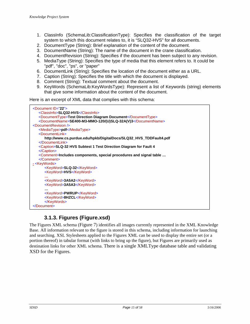
3.1.3. Figures (Figure.xsd) The Figures XML schema (Figure 7) identifies all images currently represented in the XML Knowledge Base. All information relevant to the figure is stored in this schema, including information for launching and searching. XSL Stylesheets applied to the Figures XML can be used to display the entire set (or a portion thereof) in tabular format (with links to bring up the figure), but Figures are primarily used as destination links for other XML schema. There is a single XMLType database table and validating XSD for the Figures.
<Document ID="22"> <ClassInfo>SLQ32-HVS</ClassInfo> <DocumentType>Test Direction Diagram Document</DocumentType> <DocumentName>SE400-M3-MMO-120/(U)SLQ-32A(V)3</DocumentName> <DocumentRevision /> <MediaType>pdf</MediaType> <DocumentLink> http://www.cs.purdue.edu/hpkb/DigitalDocs/SLQ32_HVS_TDDFault4.pdf </DocumentLink> <Caption>SLQ-32 HVS Subtest 1 Test Direction Diagram for Fault 4 </Caption> <Comment>Includes components, special procedures and signal table … </Comment> - <KeyWords> <KeyWord>SLQ-32</KeyWord> <KeyWord>HVS</KeyWord> … <KeyWord>3A5A2</KeyWord> <KeyWord>3A5A3</KeyWord> … <KeyWord>PWRUP</KeyWord> <KeyWord>8HZCL</KeyWord> </KeyWords> </Document>
Knowledge Project System
SDSD Page 16 of 58 5/16/2006
Figure 7 The Figure XSD
More specifically, the schema defines one single element Figure. This element has one attribute ID that gives a unique identifier in the system and the following elements:
1. ClassInfo (SchemaLib:ClassificationType): Specifies the classification of the target system to which this figure relates to, it is “SLQ32-HVS” for all documents.
2. FigureType (String): Brief explanation of the content of the figure. 3. MediaType (String): Specifies the type of media that this element refers to. It could be
"jpg" or "gif" . 4. FigureLink (String): Specifies the location of the figure either as a URL. 5. Link (SchemaLib: LinkType): Link to external documents. 6. Caption (String): Specifies the title with which the figure is displayed. 7. Comment (String): Textual comment about the document. 8. KeyWords (SchemaLib:KeyWordsType): Represent a list of Keywords (string) elements
that give some information about the content of the figure.
Here is an excerpt of XML data that complies with this schema:
<Figure ID="24"> <ClassInfo>SLQ32-HVS</ClassInfo> <FigureType>Component Diagram</FigureType> <MediaType>jpg</MediaType> <FigureLink> http://www.cs.purdue.edu/hpkb/DigitalDocs/hvs_tddfault7_components.jpg </FigureLink> <Link> <LinkType>Source</LinkType> <TableName>Documents</TableName> <Path>/Document[@ID="17"]/DocumentLink</Path> </Link> <Caption>HVS Test Direction Diagram Fault 7 Components</Caption> <Comment>SRAs with Signal and Pin Identification for Fault 7 Troubleshooting</Comment> <KeyWords> <KeyWord>3A5</KeyWord> <KeyWord>fault 7</KeyWord> … <KeyWord>TDD</KeyWord> </KeyWords> </Figure>
Knowledge Project System
SDSD Page 17 of 58 5/16/2006
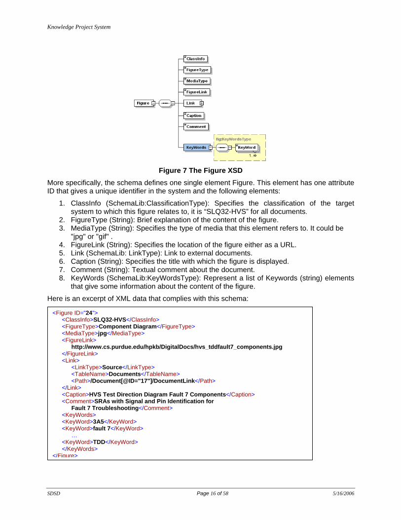
3.1.4. Smart Tables (TableDef.xsd, TableInst.xsd, TableRow.xsd) The smartTables schema represents all table information found in the technical manuals used for troubleshooting, including some information not currently listed as tables in the technical manuals, but needed by the Process and other schema as table-accessible. The smartTable schema supports row and cell-addressable information such that other XML schemas (e.g., Process, smartImage, etc) can access a specific row or cell from any smartTable. Sub-tables can also be generated on the fly, when the Process (or smartImage, Component or other XML schema) requires dynamic construction of a portion of a smartTable.
Three schemas are used to represent smart tables: TableDef, TableInst, and TableRow. Thus, three XMLType database tables and three validating XSDs are defined for smartTables:
(1) TableDef (Figure 8): Basic information about table structure, it defines one single element TableDefinition. This element has one attribute ID that gives a unique identifier in the system and the following elements:
1. ClassInfo (SchemaLib:ClassificationType): Specifies the classification of the target system to which this document relates to, it is “SLQ32-HVS” for all documents.
2. Description (String): Gives a textual description of the table. 3. Comment (String): Comment about the table. 4. Column: Column is defined by a attribute ID and an element Name(String) that gives the
name of the attribute to be instantiated. 5. KeyWords (SchemaLib:KeyWordsType): Represent a list of Keywords (string) elements
that give some information about the content of the corresponding XML document.
Figure 8 The Table Definition XSD
Here is an excerpt of XML data that complies with this TableDef schema:

Knowledge Project System
SDSD Page 18 of 58 5/16/2006
(2) TableInst (Figure 9): Tables which have the same definition but they are instantiated as different tables in the technical manuals. It defines one single element TableInstance. This element has one attribute ID that gives a unique identifier in the system and the following elements:
1. ClassInfo (tableInst:ClassificationType): Specifies the classification of the target system to which this document relates to, it is “SLQ32-HVS” for all documents.
2. TableDefinitionID (integer): The ID of the table being defined. 3. Fault (integer): The fault number. 4. PowerSupply (string): The type of power supply used by the component being
maintained.
5. Relay (string): The type of realy used by the component being maintained.
6. Link (tableInst:LinkType): Link to a document related to this table instance. 7. Caption (string): Caption describing the table. 8. Comment (string): Comment about the table. 9. KeyWords (tableInst:KeyWordsType): Represent a list of Keywords (string) elements
that give some information about the content of the corresponding XML document.
<TableDefinition ID="1"> <ClassInfo>SLQ32-HVS</ClassInfo> <Description>General signals and related data table - Appendix C </Description> <Comment>Tech Manual Source: SE400-M3-MMO-120/(U)SLQ-32A(V)3 </Comment> <Column ID="1"> <Name>Signals</Name> </Column> <Column ID="2"> <Name>Function</Name> </Column> … <Column ID="5"> <Name>Source SRA-PIN</Name> </Column> <KeyWords> <KeyWord>SLQ-32</KeyWord> </KeyWords> </TableDefinition>

Knowledge Project System
SDSD Page 19 of 58 5/16/2006
Figure 9 The tableInstance XSD
Here is an excerpt of XML data that complies with this TableInst schema:
(2) TableRow (Figure 10): Actual data in a certain table instance. It defines one single element TableInstance. This element has one attribute ID that gives a unique identifier in the system and the following elements:
1. TableInstanceID (integer)
2. RowOrder (integer): The order of the row in the table.
<TableInstance ID="4"> <TableInstance ID="5"> <ClassInfo>SLQ32-HVS</ClassInfo> <TableDefinitionID>2</TableDefinitionID> <Fault>3</Fault> <PowerSupply>null</PowerSupply> <Relay>null</Relay> <Link> <LinkType>Source</LinkType> <TableName>Documents</TableName> <Path>/Document[@ID="17"]/DocumentLink</Path> </Link> <Caption>HVS Subtest 1 High Voltage Relay and Control Fault 3 Signal Table </Caption> <Comment /> <KeyWords> <KeyWord>SLQ-32</KeyWord> <KeyWord>HVS</KeyWord> <KeyWord>Signals</KeyWord> <KeyWord>TDD</KeyWord> <KeyWord>Fault 3</KeyWord> </KeyWords> </TableInstance>

Knowledge Project System
SDSD Page 20 of 58 5/16/2006
3. LastRow (Boolean): True if it the last row.
4. Column: XML element describing the column of that data (see below)
5. Comment (string): Textual comment about the data item.
6. KeyWords (KeyWordsType): Represent a list of Keywords (string) elements that give some information about the content of the corresponding XML document.
Column is further defined with two elements:
1. ID (integer): The order of the column in the table.
2. Content defined with two elements Display (string) and Link (tableRow:LinkType).
Figure 10 The TableRow XSD
Here is an excerpt of XML data that complies with this TableRow schema:

Knowledge Project System
SDSD Page 21 of 58 5/16/2006
3.1.5. Smart Images (smartImage.xsd) The XML representation for smartImage (Figure 11) supports the use of an image-based area representation (such as that used in the HTML USEMAP) for clickable linkage to other XML schema information. The XML representation of this schema provides a way to link different parts of the figures to different elements in the other XML schema. Several XSL can be used for generating the HTML for Web browser display to view the schema in different ways.
<TableRow ID="1049"> <TableInstanceID>17</TableInstanceID> <RowOrder>2</RowOrder> <LastRow>true</LastRow> <Column> <ID>1</ID> <Content> <Display>RLCH/9</Display> </Content> </Column> … <Column> <ID>4</ID> <Content> <Display>LOW FOR 1.5s</Display> </Content> </Column> <Comment /> <KeyWords> <KeyWord>Signals and Related Data</KeyWord> … <KeyWord>Test Locations</KeyWord> </KeyWords> </TableRow>

Knowledge Project System
SDSD Page 22 of 58 5/16/2006
Figure 11 The smartImage XSD
Figure 12 Shape block (smartImage XSD): Supports the “Use Map” web browser concept More specifically, the schema defines one single element smartImage. This element has one attribute ID that gives a unique identifier in the system and the following elements:
1. ClassInfo (smartimage:ClassificationType): Specifies the classification of the target system to which this document relates to, it is “SLQ32-HVS” for all documents.
2. ImageType (string): A textual description of the use of this image, for example: “Test Image Test Image”

Knowledge Project System
SDSD Page 23 of 58 5/16/2006
3. MediaType (string): Could be either "jpg" or "gif"
4. ImageLink (string): URL of this image.
5. Link (smartimage:LinkType): Link to a document related to this image.
6. Caption (string): Textual description of the image (serves as a caption when displayed).
7. Comment (string): comment about the image.
8. KeyWords (smartimage:KeyWordsType): Represent a list of Keywords (string) elements that give some information about the content of the corresponding XML document.
9. Tag (string):
10. BoundingBox (xsd:complexType): It is a sequence of the following elements that give the coordinates to limit the smart image:
a. LeftX (integer):
b. UpperY (integer):
c. RightX (integer):
d. LowerY (integer):
11. Shape (xsd:complexType): This complex is explained below.
The element Shape is a sequence of the following elements:
1. ShapeLevel (integer): Gives the level of this shape within the smart image.
2. ShapeType (string): Takes one of the following values: "PIN", "SRA", or "SIGNAL"
3. ShapeDetail (string): Textual description of what this shape represents.
4. Tag (string):
5. Link (smartimage:LinkType): Link to a document related to this shape.
6. The last element is a choice of different geometric shapes as explained below:
a. Circle: It is a sequence of the following elements that allow a to define circle: (i) CenterX (integer), (ii) CenterY (integer), and (iii) Radius (integer):
b. Rectangle: It is a sequence of the following elements that allow to define a rectangle: (i) LeftX (integer), (ii) UpperY (integer), (iii) RightX (integer), and (iv) LowerY (integer):
c. Line: It contains one element LineSegment that is a sequence of the following elements that allow to define a line segment: SrcX (integer): (i) SrcY (integer), (ii) DestX (integer), (iii) DestY (integer), and (iv) Width (integer):
Here is an excerpt of XML data that complies with this schema:
Knowledge Project System
SDSD Page 24 of 58 5/16/2006
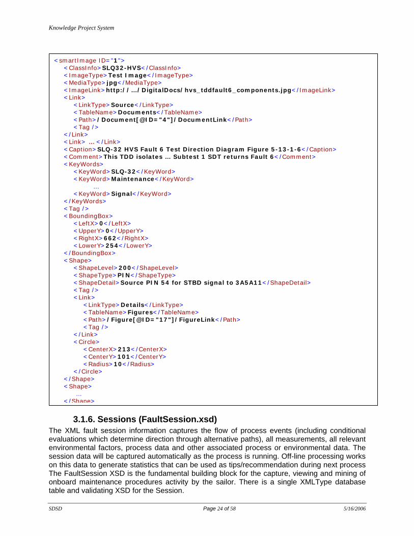
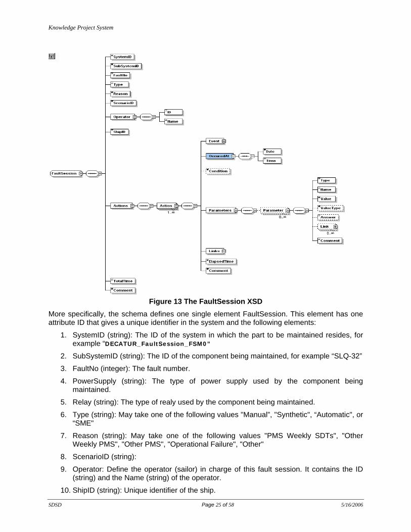
3.1.6. Sessions (FaultSession.xsd) The XML fault session information captures the flow of process events (including conditional evaluations which determine direction through alternative paths), all measurements, all relevant environmental factors, process data and other associated process or environmental data. The session data will be captured automatically as the process is running. Off-line processing works on this data to generate statistics that can be used as tips/recommendation during next process The FaultSession XSD is the fundamental building block for the capture, viewing and mining of onboard maintenance procedures activity by the sailor. There is a single XMLType database table and validating XSD for the Session.
<smartImage ID="1"> <ClassInfo>SLQ32-HVS</ClassInfo> <ImageType>Test Image</ImageType> <MediaType>jpg</MediaType> <ImageLink>http://…/DigitalDocs/hvs_tddfault6_components.jpg</ImageLink> <Link> <LinkType>Source</LinkType> <TableName>Documents</TableName> <Path>/Document[@ID="4"]/DocumentLink</Path> <Tag /> </Link> <Link> … </Link> <Caption>SLQ-32 HVS Fault 6 Test Direction Diagram Figure 5-13-1-6</Caption> <Comment>This TDD isolates … Subtest 1 SDT returns Fault 6</Comment> <KeyWords> <KeyWord>SLQ-32</KeyWord> <KeyWord>Maintenance</KeyWord> … <KeyWord>Signal</KeyWord> </KeyWords> <Tag /> <BoundingBox> <LeftX>0</LeftX> <UpperY>0</UpperY> <RightX>662</RightX> <LowerY>254</LowerY> </BoundingBox> <Shape> <ShapeLevel>200</ShapeLevel> <ShapeType>PIN</ShapeType> <ShapeDetail>Source PIN 54 for STBD signal to 3A5A11</ShapeDetail> <Tag /> <Link> <LinkType>Details</LinkType> <TableName>Figures</TableName> <Path>/Figure[@ID="17"]/FigureLink</Path> <Tag /> </Link> <Circle> <CenterX>213</CenterX> <CenterY>101</CenterY> <Radius>10</Radius> </Circle> </Shape> <Shape> … </Shape>
Knowledge Project System
SDSD Page 25 of 58 5/16/2006
Figure 13 The FaultSession XSD
More specifically, the schema defines one single element FaultSession. This element has one attribute ID that gives a unique identifier in the system and the following elements:
1. SystemID (string): The ID of the system in which the part to be maintained resides, for example “DECATUR_FaultSession_FSM0”
2. SubSystemID (string): The ID of the component being maintained, for example “SLQ-32”
3. FaultNo (integer): The fault number.
4. PowerSupply (string): The type of power supply used by the component being maintained.
5. Relay (string): The type of realy used by the component being maintained.
6. Type (string): May take one of the following values "Manual”, "Synthetic", “Automatic", or “SME"
7. Reason (string): May take one of the following values "PMS Weekly SDTs", "Other Weekly PMS", "Other PMS", "Operational Failure", "Other"
8. ScenarioID (string):
9. Operator: Define the operator (sailor) in charge of this fault session. It contains the ID (string) and the Name (string) of the operator.
10. ShipID (string): Unique identifier of the ship.

Knowledge Project System
SDSD Page 26 of 58 5/16/2006
11. Actions: A sequence of elements Action a defined below.
12. TotalTime (decimal): The total time it took to handle this fault session.
13. Comment (string): Textual comment about this fault session.
The element Action has an attribute “No” giving the sequence of this action within the fault session and the following elements:
1. Event: Describe the event related to this action with the following elements:
a. ScenarioID (string): Unique ID of the scenario.
b. EventID (string): Unique ID of the associated event.
c. EventName (string): Name of the event.
d. Skipped (Boolean): Should this event be skipped? The default value is "false"
2. OccuredAt: Give the Date (date) and Time (time) of the occurrence of this event.
3. Condition (Boolean):
4. Parameters: It is a sequence of the element “Parameter” and has the following elements:
a. Type (string): May take one of the following values "Function", "Condition", "Text", "Multiple", and "NonT". The default value is "Function">
b. Answer (string): Answer given by the operator.
c. Link (faultsession:LinkType): Link to a document related to this action.
d. Value (string)
e. ValueType (string)
f. Comment (string)
5. Links It is a sequence of the element “Link” and has the following elements:
a. ID (string)
b. Rate (decimal)
c. Comment (string)
6. ElapsedTime (decimal): The duration of this specific action.
7. Comment (string): Textual comment about this action.
Here is an excerpt of XML data that complies with this schema:
Knowledge Project System
SDSD Page 27 of 58 5/16/2006
3.1.7. SchemaLib.xsd This schema defines XML types used in different XML documents. It basically defines one simple type and four complex types:
1. ClassificationType (string): A string element defining the system. It may take one of the following values: SLQ32, SLQ32-HVS, SLQ32-DCC.
2. KeywordsType: Sequence of element Keyword (String). Represent a list of Keywords (string) elements that give some information about the content of the corresponding XML document.
3. LinkType: Has four elements a. LinType(string): It may take of the following values: Source, Details, Component
Document, Functional Document, Removal-Installation Document, Test Document, Troubleshooting Document, Block Diagram, Component Diagram, Functional Diagram, Measurement Diagram, Signal Component Diagram, Signal Diagram, Test Diagram, Test Direction Diagram, Test Direction Flow Diagram, Troubleshooting Diagram, Component Image, Measurement Image, or Troubleshooting Image.
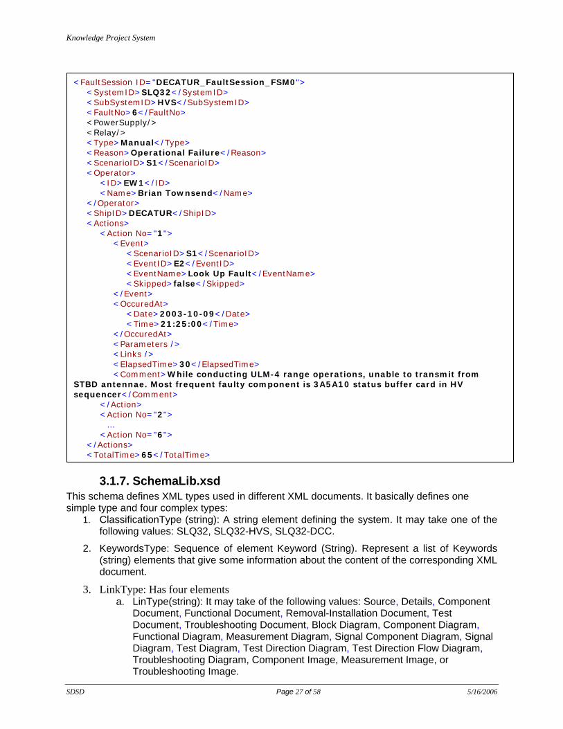
<FaultSession ID="DECATUR_FaultSession_FSM0"> <SystemID>SLQ32</SystemID> <SubSystemID>HVS</SubSystemID> <FaultNo>6</FaultNo> <PowerSupply/> <Relay/> <Type>Manual</Type> <Reason>Operational Failure</Reason> <ScenarioID>S1</ScenarioID> <Operator> <ID>EW1</ID> <Name>Brian Townsend</Name> </Operator> <ShipID>DECATUR</ShipID> <Actions> <Action No="1"> <Event> <ScenarioID>S1</ScenarioID> <EventID>E2</EventID> <EventName>Look Up Fault</EventName> <Skipped>false</Skipped> </Event> <OccuredAt> <Date>2003-10-09</Date> <Time>21:25:00</Time> </OccuredAt> <Parameters /> <Links /> <ElapsedTime>30</ElapsedTime> <Comment>While conducting ULM-4 range operations, unable to transmit from STBD antennae. Most frequent faulty component is 3A5A10 status buffer card in HV sequencer</Comment> </Action> <Action No="2">
… <Action No="6"> </Actions> <TotalTime>65</TotalTime>

Knowledge Project System
SDSD Page 28 of 58 5/16/2006
b. TableName(string): c. Path (string): d. Tag (string):
4. DatabaseCallType: Defines three elements:
a. Type (string): Could be DataRetrieval or DataStoring.
b. Name (string): Name of the database call.
c. Return: The type of object returned by this database call. May take of the following values: XMLList, XMLDocument, Image, or Text.
5. InputType: Defines three elements:
d. Type (string): Could be Function or User.
e. Name (string): Name of the input.
f. Return: May take of the following values: Boolean or Text.
3.1.8. Supporting Data (Link.xsd) The supporting data is stored in the database to provide information during the dynamic process execution, session generation, off line data mining and any other module that might need additional data structure during execution. Examples of this supporting data are (1) tables of links that maintain information about what are the appropriate links for different events in the process associated with a certain fault number (2) tables that show for each signal the source and load SRAs. Basically this supporting data includes structured data from the manuals that will be accessed during the process.
3.2. XML Tables All XML documents are stored into Oracle tables of type XMLType. For each of these tables, we assigned a trigger to enforce strict schema validation. We created the following XML-enabled tables.
1. Documents 2. Figures 3. TableDefs 4. TableInsts 5. TableRows 6. Processes 7. FaultSessions 8. smartImages 9. Links 10. TSSessions 11. TSSQueue
3.2.1. Summary XML Schemas, Documents, and Tables The following table gives a summary of the XML infrastructure (XML Schema, XML Document, and XML Table) within KPS. XML Schema (.xsd) XML Document (.xml) XML Table (Oracle) Process ScenarioS0, ScenarioS1, ScenarioSME<1,2,3>,
ScenarioSN<FaultNumber>_<sequence>, ScenarioSP_<FaultNumber>
Process
Document Document_<sequence> Documents Figure Figures, Figures_1, Figures_2, Figures_3 Figures

Knowledge Project System
SDSD Page 29 of 58 5/16/2006
TableDef TableDefs TableDefs TableInst TableInsts_1, TableInsts_2, TableInsts_3,
TableInsts_4, TableInsts_5 TableDefs
TableRow TableRows_<sequence> (1, 32) TableRows smartImage smartImage1, smartImage28, smartImage39,
smartImage4, smartImage51 smartImages
FaultSession FaultSession<sequence> (0, 15) FaultSessions Link Links, Links_<sequence> (1, 9) Links SchemaLib Used by all other XML schemas None
3.3. Relational Tables While most of the manipulated data is stored in an XML form, we defined a number of relational tables to support dynamic maintenance and data mining.
3.3.1. Dynamic Maintenance The following tables are used to support Dynamic Maintenance Event Processing and Dynamic Maintenance Resource Links Processing.
1. Load_SourceSRA: The table stores the SRAs and the SRA types given the system ID, signal and fault number. It is used by the following database functions: CheckLoadSRA, DisplayLoadSRA, DisplaySourceSRA, GetLoadSRA, GetSRAForReplacement.
2. EventLinks: This table stores the link ID for each event. It is used by the database function GetTopLinks. Tips to fill in eventLinks: the fault no 0 means that the links are independent of the fault number. They will show up with the event name regardless of the fault number. If the links go with part of the event name like Swap or Replace SRA then we can put those as the Eventname and the GetTopLinks function will handle checking the rest of the name. If the LinkId is related to an SME submitted file, then an entry is made for EventId and ScenarioId, otherwise a 'NULL' entry is made.
3. NextEvent: This table stores the next event ID and the nextNoEventID given the system ID, scenario ID, current event ID and pervious event ID. It is used by the following database functions: GetNextEvent, GetNextNoEvent.sql, GetPreviousEvent.sql.
4. SystemStartScenario : This table stores the start scenario ID given the system ID and subsystem ID. It is used by the database function GetStartScenario.
5. SystemNextScenario: This table stores the next scenario ID given the system ID, subsystem ID, current scenario ID and fault number. It is used by the database function GetEvent.
6. DatabaseCalls: This table stores the database call statement and parameter numbers given the database call name.
7. DatabaseCallParameters: This table stores the database call parameter names, parameter types and parameterDataType given the database call name and parameter ID. For In Out paramter, set ParameterType=1, otherwise set ParameterType = 0. For integer type parameter set ParameterDataType = 1, for string type parameter set parameterDataType = 2
8. Notes: This table stores the NotesType, NotesValue, NotesScenario, NotesEvent, NotesText given the ScenarioId, EventID, Answer, Fault and SignalRow. This table is used to get out of the regular scenario flow to the notes specific or general. The scenario ID is unique over the whole system does not need to be more identified with the system or subsystem. Answer is Y/N if the event is condition only this answer is considerd. Or - if DO NOT CARE. -- NotesType General Note GN /Specific Note SN -- NotesValue Text T/Scenario S

Knowledge Project System
SDSD Page 30 of 58 5/16/2006
-- NotesScenario The scenario id if the Value is scenario -- NotesText the text of the note if the NotesType is T (text)
9. EventsAfterNotes: This table stores the next scenarioID and next event ID given the current ScenarioID and EventID. It is used by the database function ExitNotes.
10. Warnings: This table stores the warning given the SystemID, SubSystemID and Fault number. It is used by the database function CheckWarnings.
11. SpecialProcedures: This table stores the Special Procedures scenario ID given the SystemID, SubSystemID and Fault number. It is used by the database functions CheckSpecialProcedures and LoadSpecialProcedure.
12. GeneralNotes: This table stores the note given the SystemID, SubSystemID and Fault number. It is used by the database function CheckGeneralNotes.
13. Synchronization: This table stores information about the files that are transported through Distance Support Mechanism. It stores the TSSessionId, MediaFileName, Version, Direction, and TimeStamp. For each media file attached to the tssession, a separate entry is made to the table. It is used by the GetNewFiles component to identify newly arrived files at the replication folder.
3.3.1.1. Table Load_SourceSRA Attribute Type Descritpion SystemId Varchar2(20) System to Trouble Shoot. It is a string with
maximum length of 20. FaultId Number(5) Fault number. It is a number with maximum length
of 6. Signal Varchar2(10) Signal ID. It is a string with maximum length of 10. SRA Varchar2(10) SRA ID. It is a string with maximum length of 10. SRAType Varchar2(6) SRAType is either ‘Load’ or ‘Source’. It is a string
with maximum length of 6. RowNo Number Each signal could have multiple source or load
SRAs. RowNo is the number of each SRA. (SystemId, FaultId, Signal, SRA)
Primary Key The primary key (SystemId, FaultId, Signal, SRA) uniquely identifies a record in this table.
3.3.1.2. Table EventLinks Attribute Type Description SystemId Varchar2(20) System to Trouble Shoot. It is a string with
maximum length of 20. SubSystemID VARCHAR2(20) Subsystem to Trouble Shoot. It is a string with
maximum length of 20. EventName VARCHAR2(200) Event Name. It is a string with maximum length of
200. FaultId Number(5) NULL Fault Number. It is a number with maximum
length of 5 and it should not be null. LinkId VARCHAR2(200) Link ID. It is a number. OrderId Number Each event could have multiple links. OrderID is
the number of each Link. EventID VARCHAR2(200) If link is related to a SME event, then the EventId
is filled in. Otherwise it is NULL. This helps us to retrieve the Links for SME submitted files.
ScenarioID VARCHAR2(200) If the link is for a file which is submitted by SME, then the ScenarioId is filled in. Otherwise it is NULL.
(SystemId,SubSystemID,EventName,LinkId)
PRIMARY KEY The primary key (SystemId,SubSystemID,EventName,LinkId)

Knowledge Project System
SDSD Page 31 of 58 5/16/2006
uniquely identifies a record in this table.
3.3.1.3. Table NextEvent Attribute Type Description SystemId Varchar2(20) System to Trouble Shoot. It is a string with
maximum length of 20. ScenarioId Varchar2(6) Scenario ID. It is a string with maximum length of
6. CrtEventId Varchar2(6) Current Event ID. It is a string with maximum
length of 6. PrevEventId Varchar2(6) Previous Event ID. It is a string with maximum
length of 6. NextEventId Varchar2(6) Next Event ID. It is a string with maximum length
of 6. NextNoEventId Varchar2(6) Next Event ID if the current condition is false. It is
a string with maximum length of 6. SystemId,ScenarioId,CrtEventId,PrevEventId)
PRIMARY KEY The primary key (SystemId,ScenarioId,CrtEventId,PrevEventId) uniquely identify a record in this table.
3.3.1.4. Table SystemStartScenario Attribute Type Description SystemID VARCHAR2(20) System to Trouble Shoot. It is a string with
maximum length of 20. SubSystemID VARCHAR2(20) Subystem to Trouble Shoot. It is a string with
maximum length of 20. ScenarioID VARCHAR2(20) Scenario ID. It is a string with maximum length of
20. (SystemID,SubSystemID) PRIMARY KEY The primary key (SystemID,SubSystemID)
uniquely identifies a record in this table.
3.3.1.5. Table SystemNextScenario Attribute Type Description SystemID VARCHAR2(20) System to Trouble Shoot. It is a string with
maximum length of 20. SubSystemID VARCHAR2(20) Subystem to Trouble Shoot. It is a string with
maximum length of 20. ScenarioID VARCHAR2(20) Scenario ID. It is a string with maximum length of
20. Fault VARCHAR2(20) Fault Number. It is a string with maximum length
of 20. NextScenarioID VARCHAR2(20) Next Scenario ID. It is a string with maximum
length of 20. SystemNextScenario_PK (SystemID,SubSystemID,ScenarioID,Fault)
PRIMARY KEY The primary key (SystemID,SubSystemID,ScenarioID,Fault) uniquely identifies a record in this table.
3.3.1.6. Table DatabaseCalls Attribute Type Description Name VARCHAR2(100) Database Call Name. It is a string with maximum
length of 100. Statement VARCHAR2(500) Database Call Statement. It is a string with
maximum length of 500.

Knowledge Project System
SDSD Page 32 of 58 5/16/2006
ParameterNumber Number Database Call Parameter Number. DatabaseCalls_PK(Name) PRIMARY KEY The primary key name uniquely identifies a
record in this table.
3.3.1.7. Table DatabaseCallParameters Attribute Type Description Name VARCHAR2(100) Database Call Name. It is a string with
maximum length of 100. ParameterID Number Database Call Parameter ID ParameterName VARCHAR2(100) Database Call Parameter Name. It is a string
with maximum length of 100. ParameterType Number Database Call Parameter Type, either 1
(InOut Type) or 0 (non-InOut Type) ParameterDataType Number Database Call Parameter Data Type such as
interger or String. DatabaseCallsParameters_PK (Name,ParameterID)
PRIMARY KEY The primary key (Name,ParameterID) uniquely identifies a record in this table.
3.3.1.8. Table Notes Attribute Type Description ScenarioID VARCHAR2(20) Scenario ID. It is a string with maximum length of
20. EventID VARCHAR2(6) Event ID. It is a string with maximum length of 6. Fault VARCHAR2(20) Fault Number. It is a string with maximum length
of 20. SignalRow Number Signal Row Number Answer VARCHAR2(1) Answer , either ‘Y’ or ‘N’ . It is a string with
maximum length of 1. NotesType VARCHAR2(2) Notes Type, either ‘GN’ (General Note) or ‘SN’
(Specific Note). It is a string with maximum length of 2.
NotesValue VARCHAR2(1) Notes Value, either ‘T’ (Text) or ‘S’ (Scenario). It is a string with maximum length of 1.
NotesScenario VARCHAR2(20) Notes Scenario. It is a string with maximum length of 20.
NotesEvent VARCHAR2(6) Notes Event. It is a string with maximum length of 6.
NotesText VARCHAR2(500) Nots Text. It is a string with maximum length of 500.
Notes_PK (ScenarioId, EventID,Answer,Fault,SignalRow)
Primary Key The primary key (ScenarioId, EventID,Answer,Fault,SignalRow) uniquely identifies a record in this table.
3.3.1.9. Table EventsAfterNotes Attribute Type Description ScenarioID VARCHAR2(20) Scenario ID. It is a string with maximum
length of 20. EventID VARCHAR2(6) Event ID. It is a string with maximum length
of 6. NextScenarioID VARCHAR2(20) Next Scenario ID. It is a string with maximum
length of 20. NextEventID VARCHAR2(6) Next Event ID. It is a string with maximum
length of 6. EventsAfterNotes_PK PRIMARY KEY The primary key (ScenarioID,EventID)

Knowledge Project System
SDSD Page 33 of 58 5/16/2006
(ScenarioID,EventID) uniquely identifies a record in this table.
3.3.1.10. Table Warnings Attribute Type Description SystemID VARCHAR2(20) System to Troubleshoot. It is a string with
maximum length of 20. SubSystemID VARCHAR2(20) Subystem to Troubleshoot. It is a string with
maximum length of 20. Fault VARCHAR2(20) Fault Number. It is a string with maximum
length of 20. warning VARCHAR2(500) Warning Message. It is a string with
maximum length of 500. Warnings_PK (SystemID,SubSystemID,Fault)
PRIMARY KEY The primary key (SystemID,SubSystemID,Fault) uniquely identifies a record in this table.
3.3.1.11. Table SpecialProcedures Attribute Type Description SystemID VARCHAR2(20) System to Troubleshoot. It is a string with
maximum length of 20. SubSystemID VARCHAR2(20) Subystem to Troubleshoot. It is a string with
maximum length of 20. Fault VARCHAR2(20) Fault Number. It is a string with maximum
length of 20. ScenarioID VARCHAR2(20) Scenario ID. It is a string with maximum
length of 20. SpecialProcedures_PK (SystemID,SubSystemID,Fault)
Primary Key The primary key (SystemID,SubSystemID,Fault) uniquely identifies a record in this table.
3.3.1.12. Table GeneralNotes Attribute Type Description SystemID VARCHAR2(20) System to Troubleshoot. It is a string with
maximum length of 20. SubSystemID VARCHAR2(20) Subystem to Troubleshoot. It is a string
with maximum length of 20. Fault VARCHAR2(20) Fault Number. It is a string with maximum
length of 20. Note VARCHAR2(500) Note. It is a string with maximum length of
500. GeneralNotes_PK (SystemID,SubSystemID,Fault)
PRIMARY KEY The primary key (SystemID,SubSystemID,Fault) uniquely identifies a record in this table.
3.3.1.13. Table Synchronization Attribute Type Description TSSessionId Varchar2(500) The unique identifier for a TSSession. MediaFileName VARCHAR2(500) The name of the file attached to the tssession. If
multiple attachments are made, then for each attachment, a separate entry is made to the table.
Version Number It is the version number of the tssession. In each iteration of the tssession, the version number is incremented.

Knowledge Project System
SDSD Page 34 of 58 5/16/2006
Direction VARCHAR2(6) It identifies if the transfer was made from ship to shore or vice versa.
TS Time Stamp It is the timestamp when the file was processed from the replication folder or copied to the master folder.
3.3.2. Data Mining Data mining information related to the dynamic process is captured via sessions, which are mined post-process to provide knowledge to be used as tips, recommendations and/or preventative maintenance information for future shipboard troubleshooting.
The following Tables are used to support data mining functions in KPS. 1. FaultSession: all the basic information of the fault sessions. 2. Action: an ordered list of the actions (executed events) in every fault session. 3. Action_Parameter: the values of the parameters associated with every action. 4. Action_Link: the list of the links accessed while performing an action. 5. Event_Node: the tree structure that captures the action flow of every fault. 6. Node_Link: the links accessed while performing the action associated with a node in the
tree. 7. Current_Node: a pointer to the current node (in the tree) that is shown in the screen
now. 8. Part: the list of all the parts in the navy. 9. Part_Ship: the list of the parts included in a ship. 10. Part_Fault_Ship: the list of the parts in a ship, which are associated with a specific fault. 11. Ship: the list of all the ships in the navy. 12. Ship_Class: the list of the different ship classes. 13. Part_Log_Ship: the time log that captures the events that occur over the parts in the
ship. 14. Part_Fault: the list of the parts associated with a specific fault. 15. Fault: the list of all the faults that can be handled in the system.

Knowledge Project System
SDSD Page 35 of 58 5/16/2006
3.3.2.1. Table FaultSession Attribute Type Description FaultSession_ID varchar2(100) Primary Key System_ID varchar2(100) e.g., SLQ32 SubSystem_ID varchar2(100) e.g., HVS Fault_No references Fault(Fault_No) Type varchar2(20) Manual, Synthetic, Codified, or SME Reason varchar2(200) Why is it started? Scenario_ID varchar2(50) Codified procedure that is followed Operator_ID varchar2(50) Operator Information Operator_Name varchar2(100) Operator Information Ship_ID references Ship(Ship_ID) Total_Time number(20,5) Time taken to finish the fault session Comments varchar2(4000) User comments Occured_At Timestamp When is it started? Processed char(1) Is it processed by the miner?
3.3.2.2. Table Action Attribute Type Description FaultSession_ID references FaultSession(FaultSession_ID) Action_Sequence_No number(5) Reflects the order of the actions action_pk (FaultSession_ID, Action_Sequence_No)
Primary Key
Scenario_ID varchar2(50) Codified procedure that is followed Event_ID varchar2(50) Event that is performed Event_Skipped char(1) Is that event skipped? Occured_At Timestamp When is it performed? Condition char(1) Answer, if the event has a “yes/no” question? Elapsed_Time number(20,5) Time taken to perform the event Comments varchar2(4000) User comments
3.3.2.3. Table Action_Parameter Attribute Type Description FaultSession_ID Action_Sequence_No action_parameter_fk foreign key(FaultSession_ID, Action_Sequence_No)
references Action(FaultSession_ID, Action_Sequence_No)
Parameter_Name varchar2(100) e.g., DB Function Name action_parameter_pk (FaultSession_ID, Action_Sequence_No, Parameter_Name)
Primary Key
Parameter_Value varchar2(100) User input value or db function return value Parameter_Type varchar2(100) User or Function Comments varchar2(4000)
3.3.2.4. Table Action_Link Attribute Type Description FaultSession_ID Action_Sequence_No action_link_fk (FaultSession_ID, Action_Sequence_No)
references Action(FaultSession_ID, Action_Sequence_No)

Knowledge Project System
SDSD Page 36 of 58 5/16/2006
Link_ID number(5) Link visited during performing this action action_link_pk (FaultSession_ID, Action_Sequence_No, Link_ID)
Primary Key
Link_Rate number(5) Score given by the user Comments varchar2(4000)
3.3.2.5. Table Event_Node Attribute Type Description Fault_No references Fault(Fault_No) Node_No number Node identifier Ship_ID references Ship(Ship_ID) event_node_pk (Fault_No, Ship_ID, Node_No)
Primary Key
Event_ID varchar2(500) Event represented in this node Count number(6) # times the event is performed Count_Skipped number(6) # times the event is skipped Sum_Time Number Total time taken (used to compute average) Min_Time Number Minimum time taken Max_Time Number Maximum time taken All_Comments Clob All the comments when the event is performed Skipped_Comments Clob All the comment when the event is skipped
3.3.2.6. Table Node_Link Attribute Type Description Fault_No Node_No Ship_ID node_link_fk (Fault_No, Node_No,ship_ID)
references Event_Node(Fault_No, Node_No, ship_ID)
Link_ID number(5) Link visited by the event represented in the node
node_link_pk (Fault_No, node_No, ship_ID, Link_ID)
Primary Key
Count number(6) # times this link is visited in this event Sum_Rate Number Total score given (for averages)
3.3.2.7. Table Current_Node Attribute Type Description FaultSession_ID Primary Key Action_Sequence_No Fault_No Node_No Ship_ID current_node_fk (Fault_No, Node_No, Ship_ID)
references Event_Node(Fault_No, Node_No, Ship_ID)
3.3.2.8. Table Part Attribute Type Description Part_SRA varchar2(10) Primary Key Part_NIIN varchar2(10)

Knowledge Project System
SDSD Page 37 of 58 5/16/2006
3.3.2.9. Table Part_Ship Attribute Type Description Part_SRA references Part(Part_SRA) Ship_ID references Ship(Ship_ID) part_ship_pk (Part_SRA, Ship_ID)
Primary Key
Last_Accessed Timestamp Last time the part is accessed in this ship Last_Replaced Timestamp Last time the part is replaced in this ship Count_Replaced number(6) # times the part is replaced in this ship Sum_Lifetime Number Total lifetime of the part in this ship (for
averages)
3.3.2.10. Table Part_Fault_Ship Attribute Type Description Part_SRA Fault_No part_fault_ship_pk (Part_SRA, Fault_No, Ship_ID)
references Part_Fault(Part_SRA, Fault_No)
Ship_ID part_ship_fk foreign key(Part_SRA, Ship_ID)
references Part_Ship(Part_SRA, Ship_ID)
Last_Accessed timestamp Last time the part is accessed in this ship fixing this fault
Last_Replaced timestamp Last time the part is replaced in this ship fixing this fault
Count_Replaced number(6) # times the part is replaced in this ship fixing this fault
Sum_Lifetime number Total lifetime of the part in this ship fixing this fault (for averages)
3.3.2.11. Table Ship_Class Attribute Type Description Ship_Class varchar2(100) Primary key Description varchar2(100)
3.3.2.12. Table Ship Attribute Type Description Ship_ID varchar2(100), Primary Key Hull varchar2(100) Class references
Ship_Class(Class)
Configuration varchar2(10) Coast varchar2(10) Variant varchar2(10)
Ship Information
3.3.2.13. Table Part_Fault Attribute Type Description Part_SRA references Part(Part_SRA) Fault_No references Fault(Fault_No) part_fault_pk (Part_SRA, Fault_No)
primary key
Knowledge Project System
SDSD Page 38 of 58 5/16/2006
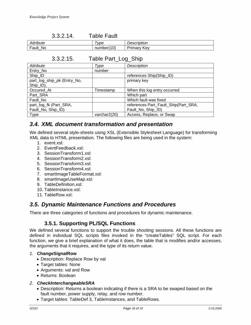
3.3.2.14. Table Fault Attribute Type Description Fault_No number(10) Primary Key
3.3.2.15. Table Part_Log_Ship Attribute Type Description Entry_No number Ship_ID references Ship(Ship_ID) part_log_ship_pk (Entry_No, Ship_ID),
primary key
Occured_At Timestamp When this log entry occurred Part_SRA Which part Fault_No Which fault was fixed part_log_fk (Part_SRA, Fault_No, Ship_ID)
references Part_Fault_Ship(Part_SRA, Fault_No, Ship_ID)
Type varchar2(20) Access, Replace, or Swap
3.4. XML document transformation and presentation We defined several style-sheets using XSL (Extensible Stylesheet Language) for transforming XML data to HTML presentation. The following files are being used in the system:
1. event.xsl: 2. EventFeedback.xsl: 3. SessionTransform1.xsl: 4. SessionTransform2.xsl: 5. SessionTransform3.xsl: 6. SessionTransform4.xsl: 7. smartImageTableFormat.xsl: 8. smartImageUseMap.xsl: 9. TableDefinition.xsl: 10. TableInstance.xsl: 11. TableRow.xsl:
3.5. Dynamic Maintenance Functions and Procedures There are three categories of functions and procedures for dynamic maintenance.
3.5.1. Supporting PL/SQL Functions We defined several functions to support the trouble shooting sessions. All these functions are defined in individual SQL scripts files invoked in the “createTables” SQL script. For each function, we give a brief explanation of what it does, the table that is modifies and/or accesses, the arguments that it requires, and the type of its return value.
1. ChangeSignalRow • Description: Replace Row by val • Target tables: None • Arguments: val and Row • Returns: Boolean
2. CheckInterchangeableSRA • Description: Returns a boolean indicating if there is a SRA to be swaped based on the
fault number, power supply, relay, and row number. • Target tables: TableDef 3, TableInstances, and TableRows.

Knowledge Project System
SDSD Page 39 of 58 5/16/2006
• Arguments: Fault number, power supply, relay, and row to display. • Returns: Boolean
3. CheckInterchangeableSRU • Description: Returns false • Target tables: None • Arguments: Fault number and row to display. • Returns: Booelan
4. CheckLoadSRA • Description: Returns a boolean indicating if there is a load SRA based on the SystemId,
faultId, power supply, relay, row number, and signal. • Target tables: Load_SourceSRA • Arguments: SystemId, faultId, power supply, relay, row number, and signal. • Returns: Boolean
5. CheckSignal • Description: Returns a Boolean indicating if there is a signal based on the fault number,
power supply, relay, and row number. • Target tables: TableDef 2, TableInstances, and TableRows. • Arguments: Fault number, power supply, relay, and row to display. • Returns: Boolean
6. CheckSpecialProcedures • Description: Returns false • Target tables: None • Arguments: Sid, SubSysID, f, and row. • Returns: Boolean
7. DisplayAllSRA • Description: Returns a String indicating the source and all the load SRA based on the
SystemId, faultId, Signal. • Target tables: Load_SourceSRA • Arguments: SystemId, faultId, Signal. • Returns: VARCHAR2
8. DisplayInterchangeableSRA • Description: Returns a String containing what are the SRAs to swap based on the fault
number, power supply, relay, and row number. • Target tables: TableDef 3, TableInstances, and TableRows. • Arguments: Fault number, power supply, relay, and row to display. • Returns: VARCHAR2
9. DisplayInterchangeableSRU • Description: Returns the string 'SRU' • Target tables: None • Arguments: Fault and row. • Returns: VARCHAR2
10. DisplayLoadSRA • Description: Returns a String indicating the load SRA based on the SystemId, faultId,
power supply, relay, Signal and row number. • Target tables: Load_SourceSRA • Arguments: SystemId, faultId, power supply, relay, Signal and row number.
Knowledge Project System
SDSD Page 40 of 58 5/16/2006
• Returns: VARCHAR2
11. DisplayNextSignal • Description: Returns a String indicating the signal based on the fault number, power
supply, relay, and row number. • Target tables: TableDef 2, TableInstances, and TableRows. • Arguments: Fault number, power supply, relay, and row to display. • Returns: VARCHAR2
12. DisplaySourceSRA • Description: Returns a String indicating the source SRA based on the SystemId, faultId,
power supply, relay, Signal. • Target tables: Load_SourceSRA • Arguments: SystemId, faultId, power supply, relay, Signal. • Returns: VARCHAR2
13. DisplaySourceSRAForAttachPulser • Description: Returns a String which is the concatenation of "Attach Logic Pulser to Source
SRA:" + the result of DisplaySourceSRA. • Target tables: Load_SourceSRA • Arguments: SystemId, faultId, power supply, relay, Signal. • Returns: VARCHAR2
14. DisplaySourceSRAForRemoval • Description: Returns a String which is the concatenation of "Remove Source SRA:" + the
result of DisplaySourceSRA. • Target tables: Load_SourceSRA • Arguments: SystemId, faultId, number, power supply, relay, Signal. • Returns: VARCHAR2
15. DisplaySpecialProcedures • Description: Displays: "sp" • Target tables: None • Arguments: Fault and row. • Returns: VARCHAR2
16. ExitNotes • Descriptions: • Target tables: EventsAfterNotes • Arguments: sID, eID, nextSID • Returns: VARCHAR2
17. ExitNotesNO • Descriptions: • Target tables: None • Arguments: sID, eID, nextSID • Returns: VARCHAR2
18. GetLoadSRA • Description: Returns a String indicating all the load SRA based on the SystemId, faultId,
power supply, relay, Signal. • Target tables: Load_SourceSRA • Arguments: SystemId, faultId, power supply, relay, Signal.
19. GetNextEvent

Knowledge Project System
SDSD Page 41 of 58 5/16/2006
• Description: Returns a String contains what the next event is based on the SystemId, ScenarioId, CrtEventId and PrevEventId.
• Target tables: NextEvent. • Arguments: SystemId, ScenarioId, CrtEventId and PrevEventId • Returns: VARCHAR2
20. GetNextNoEvent • Description: Returns a String contains what the next No Event is based on the SystemId,
ScenarioId, CrtEventId and PrevEventId. • Target tables: NextEvent. • Arguments: SystemId, ScenarioId, CrtEventId and PrevEventId • Returns: VARCHAR2
21. GetPreviousEvent • Description: Returns a String contains what the Previous Event is based on the SystemId,
ScenarioId, CrtEventId and NextEventId. • Target tables: NextEvent. • Arguments: SystemId, ScenarioId, CrtEventId and NextEventId • Returns: VARCHAR2
22. GetSRAForReplacement • Description: Returns a String contains what SRA to be swapped based on the fault
number, power supply, relay, and row number. • Target tables: TableDef 3, TableInstances, and TableRows. • Arguments: Fault number and row to display. • Returns: VARCHAR2
23. GetTextNotes • Description: Returns • Target tables: Notes • Arguments: sID, eID, F, and Row • Returns: VARCHAR2
24. GetTopLinks • Description: Returns a XMLType that contains the Related Links based on the SystemId,
SubSystemId, Fault Number, Event Name, EventId, ScenarioId, and Scenario Type. The Scenario Type helps us identify if it is an SME scenario or not..
• Target tables: Links and EventLinks. The scripts to create the table Links are in GetTopLinks (not clear!)
• Arguments: SystemId, ScenarioId, EventId and FaultId. SystemId, SubSystemId, Fault Number, Event Name, EventId, ScenarioId, and Scenario Type
• Returns: VARCHAR2
25. LoadSpecialProcedure • Description: Returns • Target tables: SpecialProcedures • Arguments: sysID, subsysID, fID, and nextsID • Returns: VARCHAR2
3.5.2. Parse Process PL/SQL Functions We defined several functions to be used in the parse process. These are:
1. extractEvent • Description: Returns

Knowledge Project System
SDSD Page 42 of 58 5/16/2006
• Target tables: • Arguments: XMLLob and eventID • Returns: CLOB
2. getEvent • Description: Returns the Scenario and event specified in the arguments or find them out if
they are null • Target tables: • Arguments: sysID, subSysID, sID, eID, and f • Returns: XMLType
3. CheckWarnings • Description: Returns • Target tables: • Arguments: sysID, subsysID, and f • Returns: VARCHAR2
4. CheckScenarioNotes • Description: Returns • Target tables: • Arguments: sID, eID, F, Row, ans, and notesEID • Returns: VARCHAR2
5. CheckGeneralNotes • Description: Returns • Target tables: • Arguments: sysID, subsysID, and f • Returns: VARCHAR2
3.5.3. Session PL/SQL Functions We defined two functions and two procedures for managing sessions.
1. getSessionID • Description: Returns unique session identifier • Target tables: dual • Arguments: None • Returns: POSITVE
2. getSession • Description: Returns • Target tables: FaultSessions • Arguments: sessionID • Returns: XMLType
3. createSession • Description: Insert into FaultSessions table the argument XML documents (xml) • Target tables: FaultSessions • Arguments: xml
4. updateSession • Description: Delete from the FaultSessions table the document for which the ID is provided
and insert the argument XML document (xml) • Target tables: FaultSessions • Arguments: sessionID and xml

Knowledge Project System
SDSD Page 43 of 58 5/16/2006
3.6. Data Mining Functions and Procedures
3.6.1. Supporting PL/SQL Functions For data mining, we defined one supporting procedure:
ReplaceSNSession
• Description: Insert into FaultSessions table the argument XML documents (xml) • Target tables: FaultSessions • Arguments: xml
3.6.2. Java Stored Procedures We defined several Java stored procedures and functions to be used by the data mining process. These are: 1. TransformAll corresponds to 'FSTransform.main(java.lang.String[])': 2. updateAll corresponds to 'Miner.updateAll()': 3. analyze (fsid varchar2, type varchar2) corresponds to 'Miner.analyze(java.lang.String,
java.lang.String)': 4. analyzeEvent (fsid varchar2) corresponds to 'Miner.analyzeEvent(java.lang.String)': 5. RetrieveSession(FSID varchar2, xLob CLOB, Type varchar2) returns CLOB and
corresponds to 'GetSession.retrieve(java.lang.String, oracle.sql.CLOB, java.lang.String): 6. GenerateSession returns varchar2 and corresponds to 'GetSession.generate():
4. Application Infrastructure The dynamic maintenance is deployed following a client-server model based on a three-tier architecture. The bottom tier consists of the knowledge base (mostly XML data) and has been detailed in the previous Section. Figure 14 gives an overall view of the different components in the systems and their relationships (control and data flow).

Knowledge Project System
SDSD Page 44 of 58 5/16/2006
Figure 14 KPS Data Flow and Control
4.1. Knowledge Projection Portal The knowledge projection portal is supported through a number of cooperating JSP programs.
4.1.1. ShipLogin.jsp The Knowledge Projection Portal connects to the knowledge base for user specified database id and password. To access online troubleshooting, sailor logs in with OperatorID, ShipID, and ship name. An error checking for valid identification is applied. It passes control to MainMenu.
4.1.2. SoreLogin.jsp The Knowledge Projection Portal connects to the knowledge base for user specified database id and password. To access online troubleshooting, sailor logs in with OperatorID and ShipID. An error checking for valid identification is applied. It passes control to MainMenu.
4.1.3. MainMenu.jsp Troubleshooting-based options. Sailor selects START or RESUME (troubleshooting session) to initiate online troubleshooting. Error checking for valid option selection. Initialization of clientMessage XML. Passes control to TSSControl. The MainMenu.jsp has also been separated for shore and ship. The menu items are seperate for each. It also changes depending if the trouble shooting sessions are open or close. If the trouble shooting sessions on the ship main menu are open then options like resume, suspend, contact shore etc are available.
clientMessage
XML
Knowledge Projection
Portal
Online Troubleshooting
KPControl
clientMessage processing and routing
TSS TSS
processing
ParseProcess scenario event processing
SaveSession event-based
fault session capture
Miner event-based
knowledge feedback
clientMessage
XML
clientMessage
XML
clientMessage
XML nextEvent nextEvent knowledge feedback
clientMessage XML HTML
nextEvent +
feedback HTML
XML Knowledge Base
clientMessage XML

Knowledge Project System
SDSD Page 45 of 58 5/16/2006
4.1.4. TSSControl.jsp TSS option processing. The clientMessage XML is updated with TSSop and current Date and Time. Passes control to StartTSS.
4.1.5. StartTSS.jsp Sailor selects SystemID, SubSystemID and Reason for troubleshooting. The clientMessage XML is updated with selections. Passes control to Maintainer.
4.1.6. Maintainer.jsp Formats web page in three frames to control troubleshooting web-based interface. Frames 1 & 3 contain HTML from KPControl. Frame 2 is a client-generated graphic:
• Frame 1: step-based guided procedure supported by execute.jsp • Frame 2: flowchart path graphics supported by flowChart.jsp • Frame 3: step-based knowledge data supported by bottom.jsp
4.1.6.1. Execute.jsp
4.1.6.2. flowchart.jsp
4.1.6.3. bottom.jsp
4.1.7. TextSession.jsp: Enables passage of free format text between ship and shore. Inputs:
1. SME name, SME email address, SME location, and task priority; 2. Questions (in text format) asked by the in-ship user; 3. Responses of the SME via phone and typed in by the in-ship user.
Outputs: all the inputs are captured and stored in a text session in the TSS in the database.
4.2. Client Side There are also other supporting procedures at the client side for database queries, error checking, and graphics generation.
4.2.1. CraneQuery.java Handles client queries to the database to retrieve data needed for user operations within the client.
4.2.2. StoredProcedureCall.java Handles client-based processing and client-to-database transfer of clientMessage XML. Also handles processing, error checking, and display preparation of the returned HTML representation of the procedure event and corresponding knowledge feedback.
4.2.3. Action.java, Chart.java Handles the construction and processing of the flowchart graphic associated with procedure actions taken so far.

Knowledge Project System
SDSD Page 46 of 58 5/16/2006
4.2.4. SaveTextSession.java This is used for capture of text sessions has been added. It has two main components, one is creating a new fault session for the first text session and secondly, appending subsequent text sessions to the already created fault session.
4.2.5. TextSessionSupport.java: This is a supporting functions of TextSession.jsp on the client side. The main function of this class, generateActionsXML(), is to construct appropriate XML content that is embedded into parameter.xml and passed to the database.
4.3. Troubleshooting Processing Online troubleshooting is started by the sailor by running the SDT and then going through the different steps (see Figure 15) as specified in the “ScenarioXXX.xml” XML document.
Figure 15 Online Trouble Shooting
In the following, we give more details on each components involved in the online troubleshooting.
4.3.1. Knowledge Projection Control The KPControl Java process serves as a router for all incoming XML messages. It responds to the KPS client and routes the XML messages according to the XML specification.
1. KPControl.java Processes and routes the incoming clientMessage XML.
• For TSSop=START, RESUME:
routes clientMessage to TSS component for TSS processing
KPControl
ParseProcess
store FaultSession saveSessio
Scenario XML smartTable XML Relational
getNextEve access
getFeedbac Relational access
genXML
genHTML Event access
AN/SLQ-32A(V)3 Shipboard ECM System

Knowledge Project System
SDSD Page 47 of 58 5/16/2006
routes clientMessage to ParseProcess component for event-based processing of Codifed (fault-based) and SME scenarios
• KPControl passes back to the client
the outgoing clientMessage containing updated values from TSS and ParseProcess
the ParseProcess-generated HTML representing the Scenario nextEvent with corresponding nextEvent knowledge feedback
2. KPControl.java Identifies TSSop from clientMessage.
• For TSSop=START, RESUME
controls troubleshooting sessions creation and determines events for appending to the event block. In particular, detects the startup of new fault sessions for appending.
3. KPControl.java Extracts TSSop from clientMessage.
• For TSSop=START, RESUME
passes clientMessage to ParseProcess for current and next event processing. Returns clientMessage and HTML document to the client for next event presentation.
4.3.2. Trouble Shooting Session Processing TSS.java Supports TSS processing.
• For TSSop=START: o TSS.start
creates a new troubleshooting session, generates a unique identifier, and initializes the header according to clientMessage
• For TSSop=START, RESUME: o TSS.append
attaches time-ordered events to the troubleshooting session event block. The TSS event block consists of status events, fault session events, free form chat events initiated by the maintainer, and SME scenario events. Fault session, scenario and chat events are appended by ID only. The IDs are pointers to the full xml object stored elsewhere in the database.
• TSS.insertLink o processes non-traditional data types submitted during scenario event processing
for representation in the external content linkage infrastructure.
4.3.3. Parse Process This Java class does the following tasks:
1. Extracts a single event from the generic process in the database
2. Resolves the database call (call supporting functions) and generate a fault specific XML
3. Calls the save session method to save the relevant information
4. Applies the XSL (xsl/event.xsl) to the generated XML and gets HTML
There are two main arguments:
1. ParamLOB: A CLOB file (XML format) which contains the parameters passsed between the client and the server.

Knowledge Project System
SDSD Page 48 of 58 5/16/2006
2. HTMLLOB: A CLOB created at the client for inserting the HTML
The following functions are defined in the ParseProcess Class:
1. connectToDB to connect to the database and initializes the global variable conn
2. getXMLDocument generates an XMLDocument type given an XMLType, a CLOB, or a file_name in an ORACLE_DIRECTORY
3. printXMLDocument applies the changes made to the XMLDocument and print it
4. writeXMLDocumentToCLOB returns CLOB (passed to it as an argument). The CLOB contains the content of the XMLDocument or XMLDocument Fragment
5. nodeExists checks whether the tag exists within the XMLElement or not
6. getValueFromDoc returns the tag value of a tag name in the XMLDocument.
7. setValueInDoc sets the tag in the XMLDocument to a certain value. Returns NULL if can't find the Tagname otherwise returns the value
8. printCLOB prints a CLOB
9. closeDBConnection closes the database connection
10. getDatabaseCallElements fills in the global variables correspond to the database call tags
ParseProcess.java Supports scenario processing of the current and next event from the specified codified or SME Scenario according to the control parameters in the clientMessage.
• processes the current event to prepare for session capture. • process the next event to prepare its representation in the client. The representation
includes next event specifications and corresponding event knowledge feedback. ParseProcess creates an XML document representing the next event by accessing information from supporting XML and relational tables which define and control procedure-related data.
ParseProcess.getEvent • extracts the targeted event from the specified scenario and, in the case of a codified
scenario, retrieves data from the fault-specific smartTable XML data layer. • processes external content links, special procedures, text blocks, specific or general
notes, warnings, and cautions, and uses the information to create an XML document. ParseProcess transforms the XML document into HTML using an event XSL.
ParseProcess.java Controls the creation and processing of the current scenario event for action-based fault session capture. ParseProcess detects the start and end of scenarios for accurate session action sequencing, and monitors triggered connecting scenarios which may represent either the continuation of the current session or the start of a new session. ParseProcess.java Processes the next scenario event to trigger collection of action-based knowledge data from the data mining layer of the knowledge base.
4.3.4. Fault Session Capture SaveSession.java Supports fault session processing. A fault session XML document is created and stored. Actions are appended with a date and time stamp. The final fault session action must be an end event to be considered complete.
SaveSession.createSession o creates a new fault session, generates a unique identifier, and initializes the
header according to clientMessage. SaveSession.appendSession
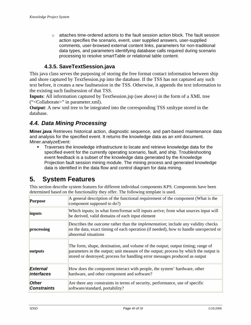
Knowledge Project System
SDSD Page 49 of 58 5/16/2006
o attaches time-ordered actions to the fault session action block. The fault session action specifies the scenario, event, user supplied answers, user-supplied comments, user-browsed external content links, parameters for non-traditional data types, and parameters identifying database calls required during scenario processing to resolve smartTable or relational table content.
4.3.5. SaveTextSession.java This java class serves the purposing of storing the free format contact information between ship and shore captured by TextSession.jsp into the database. If the TSS has not captured any such text before, it creates a new faultsession in the TSS. Otherwise, it appends the text information to the existing such faultsession of that TSS. Inputs: All information captured by TextSession.jsp (see above) in the form of a XML tree (“<Collaborate>” in parameter.xml). Output: A new xml tree to be integrated into the corresponding TSS xmltype stored in the database.
4.4. Data Mining Processing Miner.java Retrieves historical action, diagnostic sequence, and part-based maintenance data and analysis for the specified event. It returns the knowledge data as an xml document. Miner.analyzeEvent:
Traverses the knowledge infrastructure to locate and retrieve knowledge data for the specified event for the currently operating scenario, fault, and ship. Troubleshooting event feedback is a subset of the knowledge data generated by the Knowledge Projection fault session mining module. The mining process and generated knowledge data is identified in the data flow and control diagram for data mining.
5. System Features This section describe system features for different individual components KPS. Components have been determined based on the functionality they offer. The following template is used.
Purpose A general description of the functional requirement of the component (What is the component supposed to do?)
inputs Which inputs; in what form/format will inputs arrive; from what sources input will be derived, valid domains of each input element
processing Describes the outcome rather than the implementation; include any validity checks on the data, exact timing of each operation (if needed), how to handle unexpected or abnormal situations
outputs The form, shape, destination, and volume of the output; output timing; range of parameters in the output; unit measure of the output; process by which the output is stored or destroyed; process for handling error messages produced as output
External interfaces
How does the component interact with people, the system’ hardware, other hardware, and other component and software?
Other Constraints
Are there any constraints in terms of security, performance, use of specific software/standard, portability?

Knowledge Project System
SDSD Page 50 of 58 5/16/2006
5.1. Login Purpose Login allows the user to set up a connection to KPS and start a session with KPS. Inputs User name and password, in the format of strings according to Oracle requirements for
user name/password. Sailor name and ship name. The domain of sailor name can be any string that consists of English letters. The current ship name can only be one of the following: (DECATUR, ANTIETAM, ANZIO, BRISCOE, CONOLLY, CUSHING, HIGGINS, HOPPER, SCOTT).
Processing If login is refused by the database, system will prompt the user to try again. After three unsuccessful trials, no more inputs will be accepted. The user will need to restart the browser to get another set of trials. The current session will obtain a JDBC connection to the Oracle database.
Outputs The JDBC connection will be stored by the web client for the duration of the current session and destroyed when the session ends.
External Interfaces
The login accepts name/password information input by human users. This information will be sent to Oracle database for verification. Upon successful connection, the control is turned over to another module (TSS Main Menu page) from which the troubles shooting scenario can proceed.
Other Constraints
The login is implemented as a Java Server Page whose interpretation depends on an Oracle Application Server (version 9i). The web browser is Microsoft Internet Explorer (version 6.0). The implementation is portable to Apache Tomcat Application Server and Mozilla web browser.
5.2. The Fault Session component Purpose The fault session interactively guides the user throughout a trouble shooting session. Inputs • Name of system, the domain is (APS-130, SLQ-32), only SLQ-32 is
implemented; • Name of subsystem, the domain is (DCC, DTU, DSU, SIIC, FSR, XPNDR,
HVS), only HVS is implemented; • Reason to troubleshoot, the domain is (PMS weekly SDTs, other weekly PMS,
other PMS, operational failure, other); • Fault number, obtained from SDT, domain is integer within [?,?]; • Observations, measurements, and comments during fault session, domain is
alphanumerical string; • The user can select the names of technical manuals and diagrams to view; • The user answers to troubleshooting questions asked by the parse_process
component; Outputs Troubleshooting status information to the parse_process component; Processing The parse_process component decides what to do for the fault session. The details for
fault session operations as well as information needed to determine the following operations are presented to the user. Users follow the instructions and fill the information required by parse_process. History of the current fault session is shown graphically to the user.
External Interfaces
Communicates with parse_process stored procedure on the Oracle side. Troubleshooting status information is sent to parse_process. The next physical step for the session is determined by parse_process according to the status information. Upon quitting/finishing a fault session, control is turned over the TSS main menu page of the Login component.
Other Constraints
The graphical presentation of fault session history requires Java Applet and web browser with Java enabled.

Knowledge Project System
SDSD Page 51 of 58 5/16/2006
5.3. Text Session component Purpose The Text Session allows a user to obtain direct instructions from an expert during a
troubleshooting session. Inputs Messages input from a user as well as messages sent from the other party. The messages
can be in the format of text (chatting style), email, graphics, and video. Outputs The history of message exchanged between both sides is sent to the database. The user
can select which parts need to be saved. Processing User and the other party form a communication channel through which messages are
exchanged. All or partial history of these messages are stored in the database. External Interfaces
This feature requires access to remote database tables.
Other constraints
The message exchange software to support this feature is yet to be determined.
5.4. TSS Status control component Purpose This component allows the user to suspend, send to SME, resume, or exit the current
troubleshooting session. Inputs The choice of status change: suspend, send to SME, resume, and exit. Outputs The status change decision made by the user. Processing The user selects a specific choice of status change and this choice is captured and sent to
the KPS. External Interfaces
The stored procedure called KP_control.
Other constraints
Not applicable
5.5. Ship Side Linkage Infrastructure Ship Side Linkage Infrastructure for Maintainer Submitted Files
Purpose The main task of this component is to make newly created files immediately part of the KPS linkage infrastructure. We need a way to get the new files (pdf, jpg, etc) into the linkage system to be available through KPS session viewing, scenario processing and ship-shore transmissions.
Inputs Input is provided through an XML message in which a particular tag should contain the path to the new file.
Processing After executing the Ship Side Linkage Infrastructure, the new file will be part of the linkage infrastructure. It will be copied to the content directory and new links will be created for this file through new entries in the corresponding tables (Figures, Documents and Smart Table). Also, <table name> and <path> nodes are added for each text block that has a new file link. This component checks if the input is in the right format. The input is ignored if it is incorrectly formatted.
Outputs The only error message produced is if the input is not Figure (jpg, gif, bmp), Document (pdf, doc, txt), or Smart Table.
External interfaces
The only component that Ship Side Linkage Infrastructure interacts with is the database and KPControl component. It takes the input from KPControl and updates the tables inside the database.
Other Constraints
Multiple entry of the same file should be prevented.

Knowledge Project System
SDSD Page 52 of 58 5/16/2006
5.6. Ship Side Linkage Infrastructure for SME Submitted Files Purpose The main task of this component is to make SME submitted files a part of KPS
linkage infrastructure. SME submitted files are attached to the TSS document and is transported by Distance Support mechanism to ship. This module makes the newly arrived files (pdf, jpg, etc) into the linkage system to be available through KPS session viewing, scenario processing and ship-shore transmission.
Inputs Input is provided through an XML message in which a particular tag should contain the name of the new files, and other relevant information describing the attached file. The path to the Distance Support replication directory should also be provided to this component.
Processing After executing this component, the newly arrived files from shore will be a part of linkage infrastructure on ship. It will be copied to the content directory and new links will be created for this file through new entries in the corresponding tables (Figures, Documents, Smart Table, EventLinks and Links).
Outputs Only error messages are printed out if the input is not in the right format. External interfaces
The only component that this component interacts is the database and ReceiveFromShore component. It takes the input from ReceiveFromShore and updates the tables inside the database.
Other Constraints
Attached file names should be unique across the fleet. Multiples entry of the same file should be prevented.
5.7. Shore Side Linkage Infrastructure for both SME and Maintainer Submitted Files
Purpose The main task of this component is to make SME submitted files and maintainer submitted files a part of KPS linkage infrastructure. Both SME submitted and Maintainer submitted files are attached to the TSS document and is transported by Distance Support mechanism to shore. This module makes the newly arrived files (pdf, jpg, etc) into the linkage system to be available through KPS session viewing, scenario processing and ship-shore transmission.
Inputs Input is provided through an XML message in which a particular tag should contain the name of the new files, and other relevant information describing the attached file. The path to the Distance Support replication directory should also be provided to this component.
Processing After executing this component, the newly arrived files from ship will be a part of linkage infrastructure on shore. It will be copied to the content directory and new links will be created for these files through new entries in the corresponding tables (Figures, Documents, Smart Table, EventLinks and Links).
Outputs Only error messages are printed out if the input is not in the right format. External interfaces
The only component that this component interacts is the database and ReceiveFromShip component. It takes the input from ReceiveFromShip and updates the tables inside the database.
Other Constraints
Attached file names should be unique across the fleet. Multiples entry of the same file should be prevented.
5.8. Ship Side Linkage Infrastructure for SME Submitted File Get New files Component
Purpose The main purpose is to return a list the newly arrived TSS files along with their attachments. Instead of processing all the files (both old and new), this component returns only those files that are new. Thus it saves a lot of repeated processing. This

Knowledge Project System
SDSD Page 53 of 58 5/16/2006
component can be used both in ship and shore location. Inputs The input to this component is the distance support replication folder. Processing It scans the replication folder and finds out the newly arrived files by going through the
synchronization table. A list of newly arrived TSS files is created along with their attachments. For each file, an entry is made at the synchronization table.
Outputs A list of objects. Each object contains the name of the TSS file and a list of attachment made through this TSSession.
External interfaces
This component interacts with the database, Receive from Ship and Receive from Shore component. It updates the Synchronization Table in the database.
Other Constraints
All file names that are transported by Distance Support should be unique. This component only processes files according to their names
5.9. Parse Process Purpose Parseprocess (1) determines the next event from the generic process in the database, (2)
saves the current fault session, and (3) generates a fault specific HTML. Inputs Two input parameters: one holding the XML message that describes the current fault
and other relevant information, the other parameter is a placeholder for the result. Processing The following processing tasks take place in ParseProcess:
• Based on the current system parameters including scenario, event and condition, Parseprocess determines the next event from the generic process in the database. If the event is Null, Parseprocess returns an error.
• Calls the save session method to save the current fault session. • Resolves the database call and generates a fault specific XML. • Retrieves data mining information related to the event. • Returns results in HTML to the client.
Outputs The HTML to be displayed on the client External Interfaces
ParseProcess interacts with the Oracle database through a JDBC connection. All intereactions with the Web interface are routed through the KPControl component.
Other Constraints
Not applicable
5.10. SaveSession Purpose Savesession allows the creation of a new fault session and the appending of a new action
to an existing fault session. Inputs Two parameters from the Parseprocess:
1. An XML message 2. An integer array of size 2.
Processing Savesession creates a new fault session if the session ID is null otherwise it appends an action to the current fault session. Relevant information about the new fault session or action is obtained from the XML message it receives from ParseProcess.
Outputs None External Interfaces
SaveSession interacts with the Parseprocess component. It interacts with the Oracle database through a JDBC connection.
5.11. Text Block Enhancement to TSS Sessions Purpose This is an enhancement feature for user interactions with KPS. It allows the definition of
nay kind of visual elements, e.g., warnings, directions. It provides mechanisms to support client requests and to store client input to be viewed in SessionViewer (file requests, answers to questions, etc.)

Knowledge Project System
SDSD Page 54 of 58 5/16/2006
Inputs Input text blocks are read from the Scenario XML messages. The corresponding part in this XML message specifies how the Textblock will be processed and shown in the client side.
• One parameter in the XML message specifies the type of the TextBlock, it can take values ‘Request’, ‘Direction’, ‘Caution’, ‘Note’ or ‘Warning’. These options can be extended in the future.
• A Value parameter specifies the textual element that will be shown in the client side. It may have different meanings for different TextBlock types, e.g., for ‘Warning’, it stores the actual warning message; for ‘Request’, it stores the question that will be directed to the client.
• A ResultType parameter is meaningful when for a ‘Request’ TextBlock. It specifies what to expect from the user as part of the request in the client side. It can take values ‘NonT’ (file request), ‘Text’ (plain text question/answer) or ‘Multiple’ (question/answer with options).
• A Options parameter is meaningful only when the ResultType is ‘Multiple’. It specifies the reply options for the request question in the client side, e.g., yes-no questions.
• Result is meaningful when the type for ‘Request’ TextBlock is. It holds the default value of the answer to the given request.
Processing Text block is interpreted at the client side. If the type is ‘Request’, then the associated reply is routed through KP_control. If ResultType is ‘NonT’ then the linkage infrastructure appends the necessary data to access the file in the system. The resulting Text block is sent to SaveSession to be saved via ParseProcess calls.
Outputs Text block is saved into the appropriate FaultSession by SaveSession. Other constraints
Not applicable
5.12. User Interface Improvement for Session Viewer Purpose This is an enhancement feature. It makes Session Viewer easier to use with a better look
and feel and separate the slow mining viewing process from the fast session viewing. Input This session does not change the way Session Viewer works so the inputs to the new
Session Viewer is the same as the older Session Viewer Processing Session Viewer page has been separated to three frames; upper, bottom and right frames:
Most event trigger buttons (bottom page activater), all information regarding to the type of the mining process (mining process status, action id of the displayed mined data, links for the mined data) and all the browsing elements (links to other pages) were moved to this frame. Upper page contains the skeleton of Fault Session without any mining data. It has the mechanism to select a specific action type to be mined and also have triggers to update the bottom page after the mining is done. This page loads instantly. Bottom page only displays mining information for a specific action type. It is inactive initially, takes some time to be loaded and can be activated by buttons in the right frame after the mining process finishes.
Outputs Session Viewer outputs External Interfaces
Not Applicable
Other Constraints
Not Applicable

Knowledge Project System
SDSD Page 55 of 58 5/16/2006
5.13. Data Mining Purpose Provide data mining, analysis, and knowledge discovery functionalities to support
troubleshooting. Input Use information in fault sessions. Processing The data mining component analyzes the fault sessions to produce the following
statistical information: - Action History
o The average, minimum and maximum times taken to execute this action o The percentage of times this action has been skipped
- Fault History o The percentages of times every “reason”, which can result in detecting
this fault, has occurred. - Diagnosis History
o For every possible part failure that can cause this fault The percentages of times this part failure has been the actual
cause The expected procedure to fix this part failure The average time taken to complete fixing the problem
- Parts History o Both generally and fault-specific
Last time the part was accessed Last time it was replaced Number of time it was replaced Average lifetime The percentage of times it has been replaced versus all
replacements - Documents History
o The percentage of times this document was accessed o The average rate of the document, should sailors rate documents
All the above information is aggregated either over one ship, one ship class, or over the entire fleet.
Outputs Mining results as described in Processing is stored to tables in the database. External Interface
All the above information is produced as part of viewing an old session, and is produced while executing a new session. In the latter case, since the session is in action, the data mining component can suggest skipping an event to another. The skipping suggestion is based on the history of the current fault.
Other constraints
Not applicable
5.14. Troubleshooting Session The Troubleshooting Session is a major component of KP. In this section, we outline individual requirements for its different features.
5.14.1. TSS Start Component Purpose To initialize a new trouble shooting session instance (TSSession) in the relevant
(TSSessions) table in the database. The new instance will be in the form of an xml document and will conform to TSSession.xsd schema.
Input The input will be a set of parameters provided in XML format. The input will be from KPcontrol component and it requires conformance to the clientMessage.xsd schema.
Processing • A unique session Id (TSSid) will be generated for every new instance. The Id

Knowledge Project System
SDSD Page 56 of 58 5/16/2006
will be generated by concatenating the Ship ID with the unique sequence no generated from the database.
• Header structure of the new instance will be initialized in conformance with TSSession.xsd schema.
• A “Maintainer Activity” event will be added to the newly created instance. Outputs New instance of Trouble shooting session (TSSession) External Interfaces
Input interface is KPcontrol and it interacts with the database for storing the newly generated TSSession in the TSSessions table.
Other constraints
Not applicable
5.14.2. TSS Append Component Purpose To add Session, Status or SME events in the specified TSSession. Input The input will be a set of parameters provided in XML format. The input will be from
KPcontrol component and it requires conformance to the clientMessage.xsd schema. Processing • The events will be added in the TSSession.
• In case of Status events the current state of the TSSession will be updated to reflect the latest event.
Outputs Modified Trouble shooting session (TSSession) External Interfaces
Input interface is KPcontrol and it interacts with the database for storing the modified TSSession in the TSSessions table.
Other constraints
Not applicable
5.14.3. TSS Submit to Ship KPS Component Purpose To prepare the specified TSSession for submission to the KPS system on the ship. Input The input will be a set of parameters provided in XML format. The input will be from
KPcontrol component and it requires conformance to the clientMessage.xsd schema. Processing • Loading the specified TSSession from the database.
• Adding a “Queue to Shore” event to the TSSession. • Expanding the contents of all included Fault Sessions. During this expansion the
links information found in these fault sessions will also be expanded if the type of underlying link structure is “NEW FILE”. This is necessary to pass on locally generated structures to the shore where they might not exist a priori.
• The Expanded TSSession is to be then copied into trouble shooting session queue table (TSSqueue) where the type of queue is set to “Queue to Shore”.
Outputs New entry in the TSSqueue table. External Interfaces
The input interface is via KPcontrol and the output interaction is with the database for storing the new queue document in TSSqueue table.
Other constraints
Not applicable
5.14.4. TSS Send to Shore Component Purpose To submit all such TSSessions in TSSqueue which are required to be submitted to shore
to the Ship KPS. Input Null Processing • All the TSSessions marked in TSSqueue with their queue type as “Queue to
Shore” will be scanned for copying of “NEW FILES” to the KPS directory. • The file will be copied by setting its name to concatenation of

Knowledge Project System
SDSD Page 57 of 58 5/16/2006
figure/document/Image with the original file name. • The file name information will be updated in the relevant TSSessions and
updated TSSessions will be copied into the KPS directory by setting the file name as <TSSid>.xml.
Outputs New files and TSSession xml documents in KPS directory. External Interfaces
The input interface is via KPcontrol and the output interaction is with the KPS directory for storing files and documents.
Other constraints
Not applicable
5.14.5. TSS Receive All Files on Ship Component Purpose To extract all the newly received “in process” TSSessions along with attached files from
Ship KPS to update the Ship TSSessions and Processes Tables and Ship Server Tech Content directory.
Input Null Processing • All the newly received TSSessions xml files in the Ship “in process” KPS
directory are parsed and TSSessions are stored in TSSqueue with their queue type as “Queue to Ship”.
• The attached files are copied to the Ship Server Tech Content directory and the corresponding linkage information is inserted into links and events tables.
• The copied TSSessions in TSSqueue are scanned for added SME Scenarios, which if found are copied to Processes table.
• The TSSession is then copied into TSSessions table after adding a “Queue to Maintainer” event to it.
Outputs New files in Ship Server Tech content directory. New Scenario entries in Processes table. Updated TSSession entries in TSSessions table.
External Interfaces
The input interface is via KPcontrol and the output interaction is with the Database and Ship Server Tech Content directory.
Other constraints
Not applicable
5.14.6. TSS Receive All Files on Shore Component Purpose To extract all the newly received closed TSSessions along with attached files from Shore
KPS to update the Shore TSSessions and Processes Tables and Shore Server Tech Content directory.
Input Null Processing • All the newly received TSSessions xml files in the Shore “closed” KPS
directory are parsed and TSSessions are stored in TSSqueue with their queue type as “Queue to Shore”.
• The attached files are copied to the Shore Server Tech Content directory and the corresponding linkage information is inserted into links and events tables.
• The copied TSSessions in TSSqueue are scanned for added SME Scenarios, which if found are copied to Processes table.
• The copied TSSessions in TSSqueue are scanned for “unprocessed” Fault sessions which if found are copied to FaultSessions table.
• The TSSession is then copied into TSSessions table after removing the contents of all the now “processed” FaultSessions.
Outputs New files in Shore Server Tech content directory. New Scenario entries in Processes table and new Fault sessions in FaultSessions table. New TSSession entries in TSSessions table.
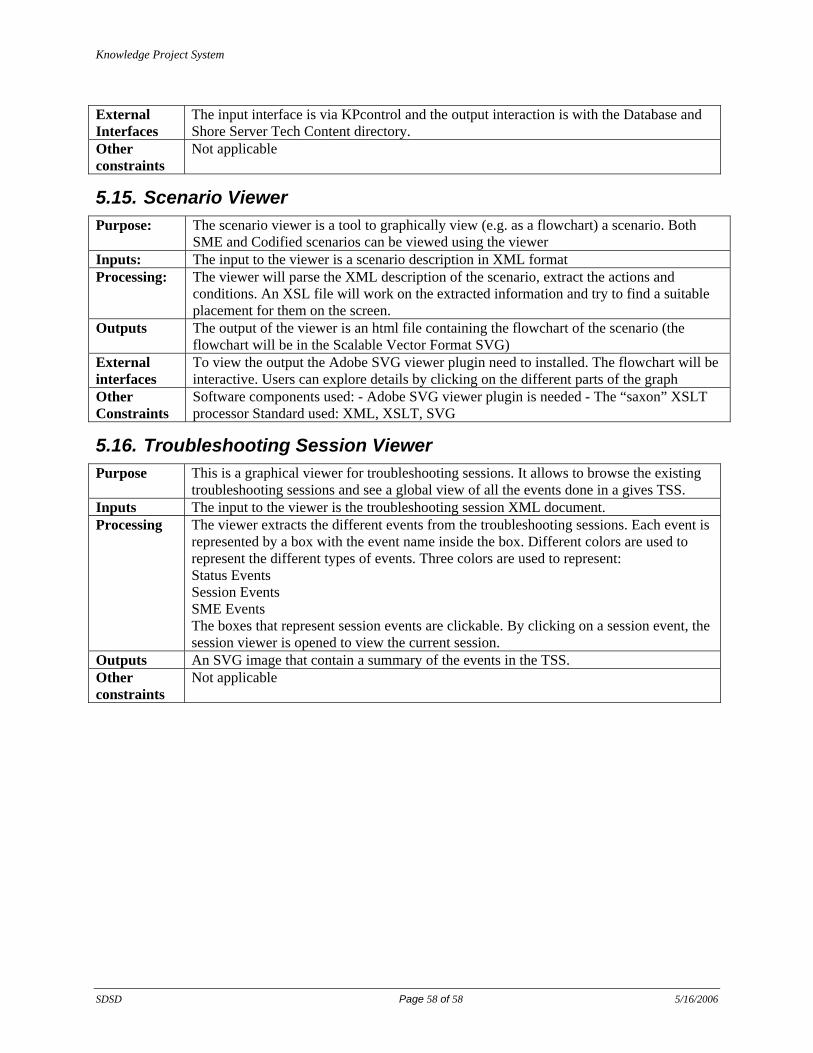
Knowledge Project System
SDSD Page 58 of 58 5/16/2006
External Interfaces
The input interface is via KPcontrol and the output interaction is with the Database and Shore Server Tech Content directory.
Other constraints
Not applicable
5.15. Scenario Viewer Purpose: The scenario viewer is a tool to graphically view (e.g. as a flowchart) a scenario. Both
SME and Codified scenarios can be viewed using the viewer Inputs: The input to the viewer is a scenario description in XML format Processing: The viewer will parse the XML description of the scenario, extract the actions and
conditions. An XSL file will work on the extracted information and try to find a suitable placement for them on the screen.
Outputs The output of the viewer is an html file containing the flowchart of the scenario (the flowchart will be in the Scalable Vector Format SVG)
External interfaces
To view the output the Adobe SVG viewer plugin need to installed. The flowchart will be interactive. Users can explore details by clicking on the different parts of the graph
Other Constraints
Software components used: - Adobe SVG viewer plugin is needed - The “saxon” XSLT processor Standard used: XML, XSLT, SVG
5.16. Troubleshooting Session Viewer Purpose This is a graphical viewer for troubleshooting sessions. It allows to browse the existing
troubleshooting sessions and see a global view of all the events done in a gives TSS. Inputs The input to the viewer is the troubleshooting session XML document. Processing The viewer extracts the different events from the troubleshooting sessions. Each event is
represented by a box with the event name inside the box. Different colors are used to represent the different types of events. Three colors are used to represent: Status Events Session Events SME Events The boxes that represent session events are clickable. By clicking on a session event, the session viewer is opened to view the current session.
Outputs An SVG image that contain a summary of the events in the TSS. Other constraints
Not applicable


![%ROHWtQ GH OD SDSD - Odepa · 3uhflr gh od sdsd hq phufdgrv plqrulvwdv vxeh hq ihuldv \ edmd hq vxshuphufdgrv (q ho prqlwruhr gh suhflrv do frqvxplgru txh uhdol]d 2ghsd hq od flxgdg](https://img.dokumen.tips/doc/110x75/5f70a3ac6bafaa12084f9105/rohwtq-gh-od-sdsd-odepa-3uhflr-gh-od-sdsd-hq-phufdgrv-plqrulvwdv-vxeh-hq-ihuldv.jpg)