Embed Size (px)
Citation preview

Knowledge Engineering for Planning-based Data-flow Composition
Mark D. Feblowitz, Anand Ranganathan, Anton V. Riabov, and Octavian UdreaIBM T. J. Watson Research Center
PO Box 704, Yorktown Heights, NY 10598, USA
Abstract
In this paper, we discuss knowledge engineering withina software composition framework, MARIO, that usesAI Planning for enabling end-users to compose softwarecomponents into data analysis flows in a goal-drivenmanner. A data flow is as a directed graph that de-scribes how data is obtained from one or more sources,processed by one or more software components, andfinally sent to one or more sinks. Such flows are of-ten used by domain experts in different domains, ondifferent platforms, to distill raw data into useful in-telligence. In many organizations, there are two roleswho are involved in developing and deploying analy-sis flows. Developers develop one or more flows andend-users pick among the available flows, and parame-terize and deploy them to obtain relevant intelligence.MARIO uses a language called Cascade for describingthe planning domain, including commonly used anal-ysis flow patterns. The patterns cover different possi-ble variations of the flows, including variations in thestructure of the flow, the software components in theflow and the possible parameterizations of these com-ponents. Developers describe the planning domain us-ing the Cascade language, a tag-based knowledge rep-resentation model, and Eclipse-based tools. For end-users, who specify composition goals, MARIO includesa web-based interface to the planner, where end-userscan specify planning goals, view the automatically com-posed flows, parameterize them and deploy them on oneor more platforms.
Introduction
A data processing flow obtains data from different sources,aggregates or integrates them in different manners, appliesdifferent kinds of analyses on the data and finally, visual-izes or handles the end-results in different ways. We viewa data processing flow as a directed graph of black-boxsoftware components (including data sources) connected bydata flow links. A flow is an intuitive abstraction that helpsdecouple the low-level details of information processingfrom the high-level view of the application. Flows are usedto describe information processing applications on differ-ent platforms including Service Oriented Systems, Event-Driven Systems, Data Mashups, Stream Processing Sys-tems, Extract-Transform-Load systems and the Grid.
Such flows are often used by experts in different do-mains, on different platforms, to obtain customized infor-mation. However, a key challenge in the use of data process-ing flows, especially by domain experts and other end-users,who are not skilled programmers, is flow assembly. Assem-bly is complex since there may be a very large number ofcomponents available, and the users may not be aware ofthe syntactic and the semantic constraints as well as the bestpractices in assembling components into complex flows.
Several visual programming tools have been developed tohelp end-users construct flows in different domains. Toolslike Yahoo Pipes (Yahoo, Inc. ) and IBM Mashup Center(IBM Mashup Center) have become fairly popular amongcasual programmers, with hundreds of thousands of flowshaving been created on them already. In the enterprise do-main, the IBM WebSphere Message Broker Toolkit (IBMWebSphere Message Broker) allows creating flows for theEnterprise Service Bus. LabView (National Instruments) isanother popular graphical programming tool for creatingdataflows.
However, in our experience, domain experts still find itvery difficult to create flows using visual composition toolsto meet their customized data processing needs. There area few reasons for this. First, even though visual program-ming environments like Yahoo Pipes make mashup con-struction more approachable for non-programmers, it stillrequires careful manual assembly of the flows by the enduser. These end-users may not be aware of composition con-straints of different components, and may also not be awareof the best practices in creating flows for their problems.Second, visual programming environments become increas-ingly difficult to use as the number of available componentsincreases and/or the size of the composed flows increases.For example, in practice end-users can compose in a goal-driven manner flows containing many tens, even hundredsof components, which are very difficult to compose quicklyusing visual tools. Finally, most visual programming envi-ronments just support a fixed set of components. They donot work very well when the set of components is extensibleand evolves with time.
AI Planning is a good candidate for tackling the challengeof flow assembly. In previous works (Riabov & Liu 2006),we had described planning approaches for composing flowsin stream processing, complex-event processing, web ser-
vices and other flow-based systems. The key idea is to modeleach component as a planning action, model any constraintson the inputs and outputs of the component as precondi-tions and effects of the planning action, and finally, modelthe properties of the information to be produced by the as-sembled flow as a planning goal. Over the last few years,we have experimented with several approaches for repre-senting the input and output constraints, for representing thegoals and for composing individual components into flows.Lately, though, we have settled on a tag-based knowledge-representation model and a pattern-based approach for de-scribing the space of available flows. We believe that theseoffer a good trade-off of expressiveness versus simplicity.
In a number of domains (such as financial services, man-ufacturing, security, etc.), end-users are reliant on an IT de-velopment team to support them in different data analysistasks. The IT team may create a set of flows for use bythe experts (often using the enterprise-side assembly toolslike WebSphere Message Broker and LabView). If the ex-pert wants to change the structure of the flow or parameter-ize it differently, she may actually have to change the under-lying flow script in the language supported by the system.This may not be practical for most domain experts. Hence,most often domain experts must refer back to the developerto change the flows to meet new needs. This lack of flexibil-ity is a big problem when the experts need to respond rapidlyto a certain situation and there is no pre-built flow that meetstheir current needs.
In this paper, we propose an approach to simplify the con-struction, parameterization and deployment of flows by end-users, especially domain experts. We make use of the obser-vation that in many domains, the set of useful flows for end-users (domain experts) often follow certain patterns. Hence,in our approach, flow developers can specify not just inde-pendent flows, but patterns of flows. A flow pattern describesa space of possible flows that are structurally similar and per-form similar tasks. Flow patterns are similar to regular ex-pressions, in the sense that just as regular expressions definea set of satisfying strings, a pattern defines a set of satisfy-ing flows. Combined with tag taxonomies, input constraints,and output descriptions, the patterns describe the planningdomain for goals specified by end-users.
Different platforms have their own flow languages, e.g.BPEL (Alves, A. et al 2006) for service-oriented systems,SPADE (Gedik et al. 2008), used in IBM’s System S StreamProcessing Platform (IBM InfoSphere Streams), Pig Latinused in (Apache Pig), etc. In addition, we often see data pro-cessing being performed using a set of shell or batch scripts.We have previously introduced Cascade (Ranganathan, Ri-abov, & Udrea 2009), our language for specifying patternsof flows. Cascade is platform and domain independent, i.e.it can be used to describe flows on any platform. It allowscomponents to be described recursively, where a compo-nent is either a primitive component or a composite com-ponent, which internally defines a flow of components. Aprimitive component can embed code snippets from anyplatform-specific flow-based language (like BPEL, SPADE,shell scripts, etc). Some of the other key features of Cascadeare an inheritance model for components, a number of ways
for parameterizing components and the ability to define dif-ferent structural variations for flows.
End-users (domain experts) explore the set of flows en-capsulated within a flow pattern and select one that meetstheir data processing needs. For this, we make use of atool called MARIO (Bouillet et al. 2008), which provides atag-based, faceted navigation user interface where users canspecify their needs (or goals) as a set of tags. MARIO thenreturns all satisfying flows to the end-user, ranked accord-ing to a pre-defined measure of cost. The composed flowscan then be translated into a flow-script in a target platform(such as BPEL or SPADE), using the code snippets em-bedded within the primitive components. MARIO uses anAI planner for composing the flows dynamically given end-user goals. In order to compose the flows using MARIO, wehave developed a Pattern Compiler that generates the plan-ning domain corresponding to Cascade patterns. The plan-ning domain includes input and output constraints that canbe used by the MARIO planner to compose flows.
Patterns provide several advantages over free-form,bottom-up composition that we have presented in previouswork (Bouillet et al. 2008). They offer a top-down, struc-tured approach to defining allowable flows rather than rely-ing on independent descriptions of individual components.In this way, they help restrict the search space of the plan-ner to a smaller set of useful flows. They also help capturereusable design patterns for information processing in a cer-tain domain.
In this paper, we focus on the knowledge engineeringchallenges that the developer faces in describing planningdomains for flow assembly in such a manner that an end-user can assemble the right flow for his need. We believe thattags offer a convenient and concise way for developers to de-scribe what kind of information a certain flow produces. Ataxonomy of tags offers a common, extensible and flexiblelingua franca for a team of developers and end-users. Themain advantage is its simplicity compared to other repre-sentation schemes like OWL. We also describe Cascade andtools available to the developer for annotating componentsand patterns of flows with tags and the typical developmentprocess involved in creating a Cascade pattern and tag anno-tations for a given problem domain. These annotations areused by the AI Planner in MARIO for composing flows inresponse to user goals. We also describe our experiences in acase study at a client’s site, where the Cascade language andassociated tools were used by developers to “deliver” flowsfor use by domain experts.
Composition Tools and Plan Execution
Before discussing our tools for planning domains in follow-ing sections, in this section we introduce the cross-platformapplication flows, into which the plans are translated in ourarchitecture, and outline the required infrastructure for goalspecification and plan execution.
Cross-Platform Flow-Based Applications
In developing our composition framework we were primar-ily focusing on enabling automated composition of stream
MARIO Goal-Driven Composer
Cross Platform Deployment
Tagged Components
Flow Patterns
StreamsBackend Plug-in
Component Bindings
MARIO application domain(s)
InfoSphere Streamsinstance
Apache Pig + Hadoop cluster
WebVizserver
Apache Pig Backend Plug-in
WebVizBackend Plug-in
Tag-Based Planner
StreamsSubflow
Cross-platform
flow
Apache Pig
SubflowWebVizSubflow
.spl .pig WebViz
EclipseTooling
Cascade
Figure 1: MARIO Architecture.
processing applications, such as those deployed in IBM’sInfoSphere Streams middleware platform. However, as wehave further observed, the techniques we developed for com-position of stream processing applications easily extend toother platforms, and specifically the platforms where com-posable applications can be viewed, at some level of abstrac-tion, as data flows. We have implemented composer proto-types that work with three different stream processing lan-guages, certain types of Web Services domains, EnterpriseService Bus message flows, SQL queries, Apache Pig appli-cations on Hadoop, IBM’s DAMIA and WebSphere sMashmiddleware, and others.
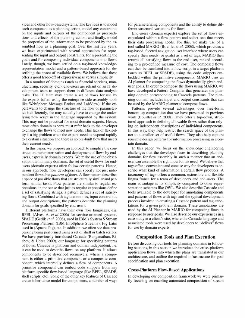
This observation led us to develop MARIO, a cross-platform flow composer, which could be used to composeand deploy applications across multiple information pro-cessing platforms. MARIO generates high-level platform-independent flows, and then invokes platform-specific back-end plug-ins to generate and deploy platform-specific im-plementations of these flows. This extensible approach letsMARIO, using a single planning domain, create and deployflows that run on multiple platforms in separation, or havedifferent components of one flow deployed in several differ-ent platforms.
MARIO represents information processing applicationsas flows, or, equivalently, flow graphs, comprised of compo-nents connected by communication links. In our current im-plementation the graphs assembled by MARIO are acyclic.
The cross-platform flow graph is a set of components con-nected by communication links sending data between theports of components, where each component includes:
• zero or more input ports;• zero or more parameters;• one or more output ports;
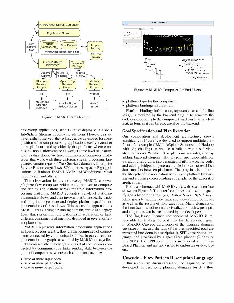
Figure 2: MARIO Composer for End-Users.
• platform type for this component;• platform bindings information.
Platform bindings information, represented as a multi-linestring, is required by the backend plug-in to generate thecode corresponding to the component, and can have any for-mat, as long as it can be processed by the backend.
Goal Specification and Plan Execution
Our composition and deployment architecture, showngraphically in Figure 1, is designed to support multiple plat-forms, for example (IBM InfoSphere Streams) and Hadoopwith (Apache Pig), as well as a built-in web-based visu-alization server WebViz. New platforms are integrated byadding backend plug-ins. The plug-ins are responsible fortranslating subgraphs into generated platform-specific code,and adding bridges to generated code in order to establishdata transfers between platforms. The plug-ins also controlthe lifecycle of the application within each platform by start-ing and stopping corresponding subgraphs of the generatedapplications.
End-users interact with MARIO via a web based interfaceshown on Figure 2. The interface allows end-users to spec-ify goals by entering tags (e.g., FilteredTrade, ByIndustry),refine goals by adding new tags, and view composed flows,as well as the results of flow execution. Many elements ofthe interface, including result visualization, titles, prompts,and tag groups can be customized by the developers.
The Tag-Based Planner component of MARIO is re-sponsible for finding the best flow for the specified goal.In MARIO, Cascade description of the planning domain,tag taxonomies, and the tags of the user-specified goal aretranslated into domain description in SPPL description lan-guage, and processed by a specialized planner (Riabov &Liu 2006). The SPPL descriptions are internal to the Tag-Based Planner, and are not visible to end-users or develop-ers.
Cascade – Flow Pattern Description LanguageIn this section we discuss Cascade, the language we havedeveloped for describing planning domains for data flow

Figure 3: Cascade flow pattern example.
composition. A more complete overview of Cascade can befound in (Ranganathan, Riabov, & Udrea 2009).
Our language improves on existing planning domain de-scription languages, when used in software composition ap-plications, in three main areas:
• Cascade improves performance of the planning algorithmby allowing the algorithm to take advantage of explicitlystated composition constraints;
• Cascade uses hierarchical and modular composition pat-terns, allowing the developers to partition the domaindescription and work on different sub-patterns indepen-dently;
• Cascade includes semantic reasoning based on a tag tax-onomy, allowing the end users to specify their composi-tion requirements generally, if needed, by selecting tagsfrom higher levels of tag hierarchies.
Cascade Graph Patterns
At the core of Cascade is the language for describing graphpatterns. The patterns serve as composition constraints re-stricting the flow graph structure. To enforce this, we usegenerated preconditions and effects in the generated plan-ning domain.
Graph pattern description consists of a few simple con-structs shown graphically using the example in Figure 3:
• Concrete components, associated with a specific platformtype and a binding.
• Composites, such as “TradeOperations”, i.e., componentswhose implementation is a subgraph comprised of a graphother components, composites, or choice nodes.
• Choice nodes: optional components, “Or” alternativesand abstract components. The optional components maybe removed from the flow graph during composition. The“Or” alternatives allow the planner to choose one of thelisted concrete components or composites. The abstractcomponents can be replaced by concrete components orcomposites implementing the abstract.
• And finally, parameters, which represent an external inputvariable requested from the end-user when plan execution
is initiated.
An example of a Cascade pattern in text form is shownin the editor window in Figure 5. It includes the definitionof a composite BIComputationCore, two concrete compo-nents BIComp_Simple and BIComp_Complex, and an ab-stract component BIComp that in our text example corre-sponds to the Calculate Bargain Index concrete componentin the figure.
Semantic Annotations of Components and Flows
Semantic descriptions in MARIO are sets of tags, i.e., key-words representing business-relevant terms that end-usersunderstand. In MARIO tags are assigned to flows in part bydevelopers, and in part automatically: the planner uses tagannotations of components assigned by developers to auto-matically compute annotations of generated flows. For validflows, the generated description of the output of the flowcontains all tags of the user-specified composition goal.
Developers annotate Cascade components by associatinga set of tags with each output port. For example, the outputof BIComp_Simple is annotated with tags Simple, Bargain-Index, LinearIndex. The planner uses these tags to computethe set of tags associated with the output of the composedflow, recursively, by taking the union of tags on input linksof each component, and associating the result with each out-put, after adding tags specified by developers on that output.Developers can also specify tags that should be removed,and associate tags with inputs. Tags associated with inputsof a component describe composition constraints: in validflows annotations of links connected to such inputs must in-clude all tags from the input annotation.
Other Annotations Allowed in Cascade
Cascade allows developers to add hard and soft security con-straints controlling the composition. MARIO can then makeuse of end user’s credentials to tailor compositions to con-form with user’s access permissions.
To explore the tradeoffs between costs and benefits of al-ternative flows matching the same goal, MARIO planner can

analyze multiple metrics associated with flows, includingcost and quality vectors. For this, the developers can asso-ciate cost and quality metrics with individual components.
Language Design Considerations
We have designed Cascade as an intermediate language thatis automatically compiled into a planning domain repre-sented in a planning domain description language, SPPL(Riabov & Liu 2006), which is an extension of PDDL. Thishas allowed our planning technology to be used by a broadercommunity of developers. In addition to the language itself,we had to develop a set of tools, which we will discuss in thenext section. However, the language itself is an importanttool that makes planning usable for software composition.
We had to address a number of challenges specific toknowledge engineering for planners when designing Cas-cade. Cascade had to be expressive enough to create newnon-trivial flows for the end users. It had to enable efficientplanning algorithms that find optimal plans in seconds (Ri-abov & Liu 2006). Finally, Cascade had to support an ef-fective development environment for domain descriptions,such that it could be easily adopted by software developerswithout requiring extensive training in logic, functional pro-gramming, or knowledge representation.
MARIO IDE
The MARIO IDE is a set of Eclipse (Eclipse Foundation)plugins that helps developers create planning domain de-scriptions by describing tag taxonomies and Cascade pat-terns, and manage and deploy them in MARIO. In this sec-tion, we describe the practical requirements for the designof the tools comprising the IDE, and their functionality. TheMARIO IDE consists of a set of editors, views and wizardsbrought together in an Eclipse perspective that cover the life-cycle of developing, testing and “executing” a Cascade de-scription of a planning domain. Broadly, the IDE tools canbe categorized as:
• Editor for the Cascade description of the planning domain• Editors for associated artifacts: (i) the tag taxonomy that
models relations between tags used as component anno-tations and (ii) the application manifest that permits cus-tomization of the end-user interface.
• Testing of Cascade patterns.• Cascade application compilation, deployment and man-
agement of MARIO servers.
We structure the rest of the section to follow the develop-ment steps outlined in Figure 4. Developers start with creat-ing a new project, followed by the definition of the Cascadepattern and components. The development stages concludewith the engineering of a tag taxonomy and an applicationmanifest. Developers typically proceed by testing Cascadepatterns.Development concludes by preparing the Cascadedescription of the planning domain for a production deploy-ment in MARIO.
Typically, the developer experience starts with the cre-ation of a new MARIO project through a customized NewProject wizard. Newly generated projects contain a few sam-ple components and a sample Cascade pattern. The com-
ponents contain very simple platform-specific code, froma backend platform chosen by the developer that is sup-ported by the MARIO server (e.g., IBM InfoSphere Stream’sStream Processing Language (SPL) (IBM )). The typicalproject structure consists of:
• A set of Cascade pattern files. Although there are no strictrequirements on how a set of patterns should be dividedinto multiple files, we will discuss guidelines for structur-ing pattern files that prove useful in practice.
• A project configuration file – this is a simple proper-ties file (key-value format) where developers can specifyserver-side properties that override the default server con-figuration for this project.
• A tag taxonomy and an application file, both in XML for-mat, for which there are special editors.
• Optionally, folders for optional resources to be used in theend-user interface (e.g., images) and for required toolk-its that Cascade components depend on (e.g., InfoSphereStreams toolkits).
The developer(s) then begin crafting the Cascade pat-terns for their domain of interest. Cascade patterns are ex-pressed in a domain-specific textual language inspired byIBM’s Stream Processing Language (SPL). Although thereare different ways in which notional Cascade patterns couldbe realized – for instance, drag-and-drop editors, descriptionlanguages supporting graphs (GraphML, even RDF) –, thechoice of syntax was motivated by the fact that many Cas-cade developers were already familiar with SPL, thereforemaking the transition to the Cascade pattern language easy.The MARIO IDE contains a syntax-highlighting editor forCascade depicted in Figure 5, also featuring code comple-tion, an outline and a framework for refactoring. The editorwas implemented on top of the Xtext (Itemis) framework fordomain-specific languages.
The syntax of a Cascade component consists of a setof annotations (contained between special markers /#* and*#/), the header and body. The special annotations are of thetype @annotation-name annotation-arguments. These aretypically the description (title) of the component, the plat-form on which the component’s code is intended to run (e.g.,@type “spl”, but only for concrete components, which haveplatform bindings) and the tag annotations on the input andoutput ports of the component (e.g., @tag oport CSV). Theheader consists of the name of the component and the inputand output ports and, for certain components the designationabstract or inheritance statements. The structure of the bodyconsists of a list of formal parameter names (if any), plat-form bindings enclosed between /$ and $/ for concrete com-ponents with specified @type, flow graph pattern descrip-tions for composite components, or empty body for abstractcomponents.
In practice, we have seen two ways of developing Cascadepatterns for an application domain. In the first developmentmode, the architect and developers start with already exist-ing custom applications that solve a similar problem. Theythen uplift the elements of these applications (e.g., opera-tors, subgraphs, etc.) into Cascade components. To aid thecreation of such components we have provided import wiz-

Figure 4: Notional development cycle with the MARIO IDE and associated tools
Figure 5: MARIO Cascade editor with syntax highlighting, outline, collapsible sections, code completion and refactoring
ards from platform languages typically used with MARIO.The import wizard for SPADE (the language for IBM In-foSphere Streams 1.2, a predecessor of SPL (Gedik et al.2008)) is shown in Figure 6(a). Finally, in step 3, the archi-tect and developers will generalize their custom applicationsinto a design patterns describing the space of solutions (an-alytic flows) for the domain. This description, in the formof the Cascade pattern, is then compiled into a planning do-main description and used by MARIO to enable end-usersto create analytic flows on the fly for their situational needs.
In the second mode of development – which typically oc-curs very soon (sometimes even the second application de-veloped) after the development team becomes proficient inCascade and the use of MARIO –, the application architectdesigns the space of solutions for the domain in the formof a Cascade pattern, typically using abstract components todenote functionality which must be implemented or refinedfurther. The use of abstract components serves multiple pur-poses during this mode of development:
• The simplest use of abstracts is as a placeholder for prim-
itive components that must be implemented in the future.• A more complex use is to abstract away entire subgraphs
of the pattern that can be delegated or detailed in a laterstage (i.e., have a composite defined that “implements”the abstract).
• A third widespread use is to divide functionality in hierar-chies (for a very specific example, consider an abstractClassifier component, from which inherit children ab-stracts such as ClusteringClassifier, SVMClassifier, De-cisionTreeClassifier; in turn, concrete clustering, SVM ordecision tree implementations will inherit from the sec-ond level abstracts).
In this mode of development, we have observed that devel-opers organize work in separate pattern files under the Cas-cade project structure. Each file contains either a refinementof a subgraph of the pattern or related concrete implementa-tions of an abstract component.
During the process of creating primitive components andcomposites, part of the development team or the architectcan begin creating the tag taxonomy using the editor de-

(a) (b)
Figure 6: (a) Import wizard for existing code; (b) Tag taxonomy editor (drag and drop tags into parent-child relationships)
picted in Figure 6(b). The tag taxonomy consists of parent-child relationships between tags that annotate the input andoutput ports of Cascade components. The tag taxonomy en-ables reasoning over the space of constraints declared bycomponents, as well as over the space of equivalent plansfor under-specified goals (for which there is more than oneplan). The tags used in the Cascade patterns are typically setsof business terms that end-users understand; with this use inmind, the MARIO IDE also features a wizard that allowstags to be imported and synchronized with an instance ofthe IBM Business Glossary (IBM Business Glossary), a toolthat permits enterprise users to define and manage businessterms and even associate them with data sources. When thetag tagsonomy is relatively stable, the application manifesteditor (Figure 7(a)) allows the customization of the end-userinterface, including the grouping and ordering of tags intofacets and the customization of the application front page.
After the completion of the Cascade pattern and associ-ated taxonomy and application manifest, the developers canuse the Cascade testing framework to test their pattern. Sinceany Cascade pattern can result in a myriad of analytic flowsbeing planed and composed based on end-users goal, thereis no easy to way to test that all the compositions describedby the pattern result in valid (i.e., compilable) applications.Using the method described in (Winbladh & Ranganathan2011), developers can generate a small number of test plansand applications embodying these plans that have been em-pirically shown to catch the vast majority of common errors.The interface for the testing framework (Figure 7(b)) is in-spired after the JUnit interface, with the important differencethat developers choose a testing methodology and parame-ters. Tests are automatically generated and compiled (poten-tially on a remote machine) by the IDE. The developers canretrieve generated code; the IDE places markers where com-pilation errors have been reported.
Finally, after testing, the developers have the option offield-testing their Cascade patterns on a MARIO server.MARIO projects are by default compiled into a planningdomain specification on every save (if enabled in Eclipse);errors are displayed in the usual way, using the Problemsview, as well as markers in the Cascade editor. The MARIOServers view (Figure 8(a)) allows developers to define thelocation of MARIO installations, potentially on remote ma-chines, and also change some common configuration ele-ments for the servers (e.g., the HTTP port numbers). TheIDE communicates with the MARIO servers via ssh and scpusing private–public key authentication. After a server loca-tion has been defined, developers will be prompted to choosethe MARIO application they want to run when starting theserver. The application will then be recompiled and the gen-erated planning domain specification and associated taxon-omy, manifest and other artifacts (configuration, libraries)uploaded to the server. Server log messages are displayedin a separate Console view. The developers can double-clickthe running server to bring up the MARIO user interface ina stand-alone browser window; they can also drill down andlook at any the application source code generate by the plan-ner as a result of end-user goals and bring that source codeback to the MARIO IDE machine for inspection. Serverssupport one-click restarts when any element of the MARIOproject is changed by the developers. After field-testing theapplication, the developers can export a compiled MARIOproject (Figure 8(b)) to a zip file or directory on a local orremote machine. The exported file or directory can be usedto start production MARIO servers for the application.
Discussion
We have implemented an automated composer, MARIO,and Cascade, a language for describing flow-based softwarecomposition domains, and a full set of development tools forCascade, including an Eclipse-based IDE. These tools have

(a) (b)
Figure 7: (a) Application manifest editor; (b) Cascade testing framework
(a) (b)
Figure 8: (a) MARIO server management from IDE; (b) Export wizard
been used in pilot deployments since 2009, and we havemade modifications and improvements based on experienceand feedback from these deployments.
Installing the tools requires a target deployment environ-ment supported by the tools. For the main branch of our toolswe require Hadoop or IBM’s InfoSphere Streams, althoughwe had built experimental prototypes for other platforms.
The tools have reached the level of robustness required tobe applied in real-world applications.
These tools have been applied in a data analysis domain,where a total of 5 developers (also referred to as technicalanalysts) developed flow patterns for use by a total of 20domain experts (also referred to as business analysts). In thiscase study, all composed flows were converted to the SPADElanguage, and were deployed on IBM InfoSphere Streams.
In one case study 4 different applications were developed.Each application targeted a certain data processing problemand consisted of a set of patterns. Each application was de-
veloped by a small team of developers and was delivered foruse by a team of domain experts, as follows:
• Application 1 had 2 Developers and 2 Business Analysts• Application 2 had 2 Developers and 8 Business Analysts• Application 3 had 3 Developers and 6 Business Analysts• Application 4 had 3 Developers and 8 Business Analysts
Some key high-level statistics on the usage of patterns are:
• Number of Cascade patterns : 16• Number of Cascade components : 186• Total number of assemble-able flows : 1200+• Number of applications imported from existing flows : 2• Number of applications built from ground up : 2
We also received feedback from three of the developersabout some properties of the patterns they created. Table 1summarizes this feedback.
While the statistics we have collected so far are from arelatively small sample set of developers, they give us some

Developer 1 Developer 2 Developer 3
Number of patterns developed 8 2 4Number of components in patterns Max: 20, Avg: 10 26 in one pattern,
20 in the otherMax: 20
Max depth of composite-containment hierarchy(i.e. composites containing other components)
4 4 3
Max depth of component-inheritance hierarchy 3 2 2Max branching factor in enumerations 7 4 5Max number of flows in a pattern 1084 36 25How were the patterns created Generalized
Existing FlowsFrom scratch From scratch
Table 1: Feedback from 3 Cascade developers
hints on the usage of patterns. Firstly, developers are com-fortable in terms of partitioning a flow in a native flow lan-guage into different Cascade components and organizingthese components hierarchically in high level composites.The also made use of different features of the language, in-cluding the component-inheritance and specifying structuralvariations. While one the developers always started by firstcreating a SPADE flow and then generalizing it into a pat-tern, the others started coding the flows and the patterns to-gether (i.e. they had the space of possible flows in mind fromthe very beginning).
We also asked the developers about the reasons for cre-ating the patterns. The main reason was to support differentkinds of custom processing and alerting requested by do-main experts. They said that with the delivery of the patterns,the number of individual requests from the domain expertsfor small modifications to the pattern had significantly de-creased. The domain experts were more self-sufficient withthe use of the patterns and the end-user interface. There wasstill some communication between developers and the do-main experts, which mainly involved getting requirementsand feedback; however the frequency of this interaction haddecreased since they started using patterns.
The developer tools aided the development of patterns.For example, Developer 1 said that the first pattern took him4 hours to develop (he was generalizing an existing SPADEflow). However, he was able to develop subsequent patternsmuch more rapidly.
Overall the feedback we received from developers waspositive and encouraging. At the same time automated com-position brings new challenges to developers. One notableexample of the new class of development challenges arechallenges originating from the use of code generation inMARIO. Debugging automatically generated code on vari-ous platforms and tracing back problems to Cascade sourcewas not always easy. To address this, at deployment time,MARIO saves generated code to make external debuggingpossible, and includes comments in generated code referringto the original Cascade components. And at developmenttime, the testing framework included with the IDE helpsidentify problems by automatically composing and testingmultiple instantiations of the patterns.
AcknowledgementsThe authors thank their former colleagues Eric Bouillet,Hanhua Feng and Zhen Liu for critical contributions toMARIO project. The authors also thank MARIO pilot par-ticipants for providing invaluable feedback.
ReferencesAlves, A. et al. 2006. Web services business process execu-tion language version 2.0. OASIS Committee Draft.
Apache Pig. http://pig.apache.org/.
Bouillet, E.; Feblowitz, M.; Liu, Z.; Ranganathan, A.; andRiabov, A. 2008. A tag-based approach for the designand composition of information processing applications. InOOPSLA, 585–602.
Eclipse Foundation. Eclipse Project. http://eclipse.org.
Gedik, B.; Andrade, H.; Wu, K.-L.; Yu, P. S.; and Doo, M.2008. SPADE: the System S declarative stream processingengine. In SIGMOD 2008, 1123–1134.
IBM Business Glossary. http://www.ibm.com/software/data/infosphere/business-glossary.
IBM InfoSphere Streams. http://www.ibm.com/software/data/infosphere/streams/.
IBM Mashup Center. http://www.ibm.com/software/info/mashup-center/.
IBM WebSphere Message Broker. http://www.ibm.com/software/integration/wbimessagebroker/.
IBM. IBM InfoSphere Streams SPL Specification.http://publib.boulder.ibm.com/infocenter/streams/v2r0.
Itemis. Xtext Framework Documentation.http://xtext.itemis.com.
National Instruments. Labview. http://www.ni.com/labview.
Ranganathan, A.; Riabov, A.; and Udrea, O. 2009. Mashup-based information retrieval for domain experts. In CIKM,711–720.
Riabov, A., and Liu, Z. 2006. Scalable planning for dis-tributed stream processing systems. In ICAPS.
Winbladh, K., and Ranganathan, A. 2011. Evaluating testselection strategies for end-user specified flow-based appli-cations. In ASE, 400–403.
Yahoo, Inc.. pipes.yahoo.com.