Embed Size (px)
Citation preview

Knowledge Based Methodologies versus Conventional Optimisation Algorithms: Applications to Reactive Power Compensation.
R. Cicoria and P. Migliardi ENEL-DSR/CREI (Italy)
P. Marannino ENEL-DSR/CRA (Italy)
KEYWORDS: Power Application Software, Expert Systems, Reactive Power Compensation.
ABSTRACT
Knowledge Based Methodologies or Expert Systems (ES) may provide a useful tool either in handling conventional computer programs for power system analysis and planning or in managing the large amount
· of relevant input/output data. This paper describes an application of an ES
managing a conventional load flow program in order to get rid of many difficulties connected with the running of critical cases, such as non convergence or voltage and V AR violations and allowing the set up of reactive power resources, if needed. The same cases have also been treated with an Optimal Reactive Power Flow (ORPF) program, and advantages or drawbacks are pointed out for both procedures.
The ORPF requires more highly qualified expertise to be fully exploited in comparison with the ES.
1. Introduction
When facing a power system analysis and planning problem [l], engineers usually have to deal with conventional computer programs based on analytical deterministic algorithms.
The more power systems have grown in size and complexity and the more automatic calculations have been used, the more the need has arisen to handle large amounts of data to prepare or of results to analyse; the former is a tedious and low productive activity often performed by qualified staff; the latter can become a difficult task especially when computer programs are run in peripheral departments of the utilities where specialized expertise is not easily available. Both are prone to human errors.
Expert Systems can prove very practical in increasing the overall productivity of the power board if they carry out repetitive activities and spread highly qualified experience among a wide area of users.
Other advantages can also motivate the sudden rise of interest in these techniques:
- increasing the knowledge and improving the results is a more practical possibility;
411
- quality and reliability of results are achieved through a unified heuristics and do not depend any more on the ability of the operator;
- detailed explanation of the decisional procedures carried out is fully available and very useful for training purposes. The above technique has been adopted by ENEL for
a few years, when the decision was made to develop a prototype of a Knowledge Based System able to perform the annoying and time consuming procedure of recursively running the load flow program in the planning stage of a network.
As well known, the load flow calculation may not converge in a solution or, if it does, this can be affected by some violations of the operation constraints:
-line power flow above the thermal threshold; -bus voltage outside the admissible range; -generator power outside the capability limits. The run is usually repeated, after a correction of
options and input data, until a feasible solution is reached.
The ENEL ES addresses the definition of a workable operation point issue by means of reactive compensation and voltage control with the assumption that the active power generations have already been settled in order to cope with the current flow constraints.
It is to be pointed out that ES is utilized here not because of the impossibility of reaching a solution through mathematical methods, but for its specific ability to manage conventional computer programs that otherwise would require a great deal of expertise to be effectively run. Such ES has been designed to be applied in the planning rather than in the operation context.
In the meantime at ENEL the BACONE procedure [2], belonging to the family of ORPF programs, is also being applied. This allows very accurate results, yet requires high level knowledge and experience-based judgement.
Both methods are being pursued, taking advantage either of the ES performances from the point of view of user-friendliness and the evidence of explanation or of the peculiar features of ORPF, yielding precise solutions in a timely fashion.
Subsequent sections contain a description of the structure of SELF [3], the ENEL Expert System to drive the load flow program (named FLOW AC, implementing
the Newton-Raphson decoupled algorithm) which has been integrated, together with other packages for RV network planning, in a computer environment (SPIRA SYSTEM) [4] which exploites data bases, graphics and interactive procedures.
An outline of the BACONE program follows; in comparing with SELF, only one feature of the program is considered: the calculation of the minimum amount of reactive power to be supplied in pre-determined buses in order to get rid of voltage-V AR unbalances.
Several practical cases have been processed by either SELF and BACONE on a APOLLO-HP9000/400S workstation. The results of both procedures have been compared; two of them are reported in this article: on the 57 buses AEP test system and on a 421 buses model of the Italian RV /EHV network.
2. The architecture of the SELF
The natural reasoning procedure has been generally simulated in Artificial Intelligence (AI) [5] by a production system. Up to now most of the AI applications in power systems [6] use production rules (the typical frame if-then-else) for the heuristic knowledge representation.
Instead, the needs of the voltage-V AR unbalance elimination required to directly implement in SELF a heuristic search algorithm [5] in a wide state space.
A state is the network situation expressed by the values of the dependent and independent variables. When there are no violations this is termed goal state. The goal state is attained by means of a set of moves, i.e. variations of independent variables selected and triggered by a proper control strategy in which the heuristic knowledge is mainly resident.
The approach with production rules and inference engine seemed adequate only to address the load flow non convergence cases. A first experiment "ith a commercial shell was succesfully conducted.
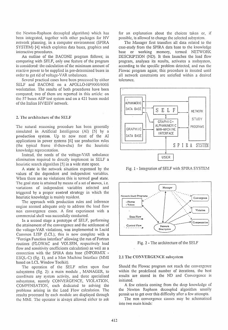
In a second stage a prototype of SELF, performing the attainement of the convergence and the settlement of the voltage-V AR violations, was implemented in Lucid Common LISP (LCL); this is now complete with a "Foreign Function Interface" allowing the run ofFoi;tran routines (FLOW AC and VOLSEN, respectively load flow and sensitivity coefficients calculation) as well as a connection with the SPIRA data base (INFORMIX -ESQL-C) (fig. 1), and a Man Machine Interface (MMI based on LCL Window Toolkit).
The operation of the SELF relies upon four subsystems (fig. 2) : a main module , MANAGER, to coordinate any system activity, and three specialised subsystems, namely CONVERGENCE, VIOLATION, COMPENSATION, each dedicated to solving the problems arising in the Load Flow calculation. The results processed by each module are displayed through the MMI. The operator is always allowed either to ask
412
for an explanation about the choices taken or, if possible, is allowed to change the selected subsystem.
The Manager first transfers all data related to the case-study from the SPIRA data base to the knowledge base or working memory, termed NETWORK DESCRIPTION (ND). It then launches the load flow program, analyses its results, activates a susbsystem, according to the specific problem detected, and run the Flowac program again; this procedure is iterated until all network constraints are satisfied within a desired tolerance.
ALPIWAA.[R IC
DATA BASEk-H s E L F L ~---k-1\_ GRAPHIC
ALPHANUMER IC GRAPH IC ""'" - MAN-MACH I NE ~
DATA BASE INTERFACE
NETWORK
STUDY
PROGRAMS
S P I R A SYSTEM
[ USER l Fig. 1 - Integration of SELF with SPIRA SYSTEM
Network Study Progr:uru
'"'flOW<IC
-Vol5rn
Dal3 Flow
Control Flow •• • •••••• )o
... . · ..
· 1 Convcri:<nce)
Viot.ilioo )
Fig. 2 - The architecture of the SELF
2:1 The CONVERGENCE subsystem
' Should the Flowac program not reach the convergence \\ithin the predefined number of iterations, the best results are stored in the ND and Convergence is initiated.
A few criteria coming from the deep knowledge of the Ne\\1on Raphson decoupled algorithm usually permit us to get over this difficulty after a few attempts.
The non convergence causes may be schematiscd into two main kinds:

- numerical, related to an insufficient iterations number or to an inadequate residual tolerance;
- physical, when a severe reactive power unbalance affects an area.
In the former case the maximum iteration number and, subsequently, the active and reactive mismatch tolerance will be increased.
In the latter, the highest reactive residual node will be located since this is supposed to be the center of the area affected by reactive deficit: its type is changed from PQ to PV if it is a generator. If not, the above mentioned PQ-load node is left and the PQ-generator nodes with reactive residual are considered; the one with the maximum residual (heuristic criteria adopted for evaluating the proximity to the highest residual PQload) will be converted to PV. Only if there are no PQgenerators with reactive residual, will a PQ load bus be transformed to PV, that is, it will become a compensator node. In any case the PV desired voltage value will be set according to simple heuristic rules.
Such an algorithm was suitable for implementing through a rule-based system.
Any non convergence problem occured in practical cases has been up to now succesfully overcome.
2.2 The VIOLATION subsystem
This module represents the outstanding feature of SELF, being based on a sophisticated reasoning model and being activated most frequently.
Violation tries to simulate the planning operator behaviour when, trying to eliminate one violation at a time, he modifies the independent variable of a bus in order to influence another bus dependent variable. The difference here is that any variable shift effect is previously assessed through the linearisation of the network model instead of by the execution of a new load flow. Yet it must be taken into account that the larger the changes, the higher is the likelihood of load flow results not matching with linear analysis.
Knowing the nodes where voltage and V AR are out of the admissible limits, a number of controllers (i .e. all the PV nodes, the slack node and the PQ-generator nodes) for each violated node are located; then a set of controlled buses is searched for with regard to each controller. The selection is carried out by filtering through appropriate thresholds the sensitivity matrices [3] , computed by the Volsen routine.
The overall heuristic search algorithm for the execution of one move can be summed up as follows :
1) A violated bus is selected depending on the node type (first PQ-nodes, then PY-nodes}, controller status (first buses being also controller}, rated voltage (first higher voltages) and dependent variable unbalance amount (i .e., for a PQ-node, the ones with maximum voltage violation).
2) The controller set is checked in order to consider only those where the reactive power generation can be
413
modified in the proper direction: the remaining are classified as non activable.
3) The controllers of a violated node are classified by means of four criteria: a) their qualitative influence on controlled nodes:
either positive (i.e. they improve the controlled bus situation) or negative (i.e. they make the situation worse) or not valuable (when they keep unchanged the previous non violated situation);
b) coincidence between controller and violated bus; c) their quantitative influence on the selected violated
node, measured through the sensitivity coefficients; d) the p.u. availability of their independent variable to
be shifted; controllers with low availability will be preferred to avoid significant displacement from the working point.
4) Starting from the first controller classified in point 3, the beginning state S0 is "explored", i.e. a set of possible moves is determined by considering the "prominent variations" for each controlled bus, in other words by working out (via sensitivities) the independent variable changes that cause either the elimination of the violation or a new violation in the controlled bus.
For each possible move i the following evaluation function h(Si) [3], that linearly combines the voltage and reactive power unbalance, is calculated:
h(Si ) =a·· violy. +a-· violy_ +/f ·violQ+ +fJ·violQ:
where:
Si is the state corresponding to a possible move i;
a· , a -,fr ,p-are weighing factors determined by heuristic criteria in order to differentiate the contribution of each type of violation (for instance considering too high voltage violations more seriously than too low);
viol v· , viol v- , viol Q" , viol Q-
are the total absolute violation amount in p.u. subdivided by the variable (V or Q) and by the relative sign corresponding to the state Si.
The move to be actually executed refers to the state S with h(S) minimum and less than h(S0) being S0 the starting state.
The above steps, move by move, are repeated until : a) every violation is settled (goal state); b) any controller proves to be ineffective;
c) h(S) decrease exceeds the limit value ~~x&
~hMAX has been set on the base of experience acquired during the studies on actual networks, in order to avoid large changes and to hold as much as possible the working point.
Aftenvards the Violation subsystem is ended and the Flowac program is run again.

STEPl PV Nodes with Reactive Power Violation Violated bus Node Name Q-Violation (MVAr)
Selection Ostiglia MV 32,865
Brindisi Sud MV 33,077 SELECTED NODE
Porto Tolle MV 7.42
STEP2 Node Name Node type V rated (kV V-cur (kV) Qmin (MVAr) Omax (MVAr) Q-cur (MVAr) Controller set Brindisi Sud MV PV 20 21 ,00 -1480,00 1296,00 1329,10 ACTIVABLE determination Mucone 1 PQ 11 9,68 -88,00 45,00 2,70 ACTIVABLE
Mucone 2 PQ 11,2 9,85 -64,00 34,00 2,20 ACTIVABLE Brindisi 220 MV PQ 20 20,00 -125,00 167,00 167,00 Brindisi 380 MV PQ 20 21,00 -250,00 334,00 333,24 Castrocucco PQ 10 9,31 -60,00 40,00 24,60 ACTIVABLE Rossano PQ 20 19, 15 -375,00 501,00 319,80 ACTIVABLE
Tusciano PQ 9 8 ,44 -10,00 4,00 4,00 TABLE 1 ····· ··· ··· ···· ·· ... ... ······ ······· ... .. .. ... .. ... . . . . . . . . . . . . . . . . . . .............. .... .. .... ... .. ... ... ...... ... ... ...... .. .....
STEP 3 Node Name Node type Any node Same node Sensitivities lndep . Var. Chosen? EXPLANATION
OF AMOV~ Controllers worsenina? (p .u,J Availabilitv(p ,u,J Sorting Brindisi Sud MV PV yes yes 1 1 before NO MOVE
Mucone 1 PQ yea no 0,788 0,318 YES Mucone 2 PQ yes no 0,788 0,325 later Castrocucco PQ yes no 0,728 0,154 later
Rossano PQ ves no 0 ,688 0,207 later The chosen controller node MUCONE 1 has a Reactive Power range of 42.3 MVAr, considering its own voltage limits
STEP4 Nodes worsenin : Brindisi 380 MV Torvaldaliaa 380 MV
Move MUCONE 1 MV Prominent Variation
Calculation MVAr Va ria tion
18,335 Violation cancelled in: Corriolo 2 30,958 Violation cancelled in: Feroleto 31,199 Violation cancelled in: Mucone 1
36 ,854 Violation cancelled in: Scilla 41 ,967 Violation cancelled in: Brindisi Sud MV
The explanation facility of the SELF deserves some further description : Table 1 presents the four steps, illustrated above, leading to the calculation of a move related to a Q-violated node (Brindisi Sud MY) of the Italian 220/380 kV network.
The first step shows the selection of the current violated node among the three considered: Brindisi Sud MV is both a controller and the one with the highest violation.
In the second step, a set of controllers of the node Brindisi Sud MV is selected through proper sensitivity filtration; four of them are found to be with a sufficient reactive power margin and therefore are declared "activable" ; this applies also for Brindisi Sud MV where the voltage must be reduced to decrease the violation of 33 .077 Mvar.
From these, the sorting performed in the third step determines the nodes Mucone 1 and Mucone 2 as the most suitable controllers since they are the ones with the second highest p.u. sensitivity; Mucone 1 is selected because it has the lowest reactive power availability. It is to be noticed that the node Brindisi Sud MV has the highest p.u. sensitivity, but it has been previously chosen : no move was executed because the new situation would have got worse.
In the last step, the finite set of moves on the activated controller is being computed until the fifth is found that cancels the considered violation; despite the existence of nodes that worsen when the independent variable increases, the evaluation function h(S) decreases.
414
h(S) reduction
0 ,2392 0 ,3769 0 ,3794
0.4257 0,4633 MOVE EXECUTED
2.3 The COMPENSATION subsystem
Should the Violation subsystem fail in its task to restore the voltage profile and the V AR admissible production, the module Compensation will be started in order to automatically supply needed V AR resources.
Violation subsystem failure can be due to: a) lack of activable controllers; b) poor improvement of the previous situation, noticed
when the Evaluation Function decay is no longer significant.
The module substantially resumes the Violation scheme, but specific criteria and parameters have been added.
A number of compensator "candidates" is chosen among the most violated load buses and the HV /EHV nodes connected through step-up transformers to PV generators beyond reactive power capability limits.
Candidates are assigned a V AR generator whose output is driven by the usual sensitivity based mechanism, until any variable is brought into desirable range (COl'vfPENSA TION phase A).
A few previously running generators are likely to be unloaded by the new injection of reactive power: some further cycles are therefore performed seeking to minimize the rating of compensation banks to be set up. This is carried out by reducing to zero the capability limits of the activated compensator nodes in order to detect Q-violations. Such violations are treated by redispatching the reactive power generation of the whole network keeping, at the same time, the voltages within the desired limits (COl'vfPENSATION phase B).

3. The BACONE procedure
The BACONE procedure is applied to the optimisation of the voltage profiles and the reactive power distribution among various resources in V AR planning of electric systems.
It operates in two successive steps; the first determines a workable operation point and the second pursues the optimal V AR installation from an economic aspect.
At first, the minimum investment in new V AR compensation devices is sought in order to guarantee adequate security for the planned systems. The solution of this problem is reached by a linear ORPF algorithm.
Afterwards, the procedure determines the most economic installation by minimizing the sum of the annual cost of active losses and of the annuity of additional V AR resource investment: a non linear optimisation problem is therefore solved by means of the well known HAN-POWELL algorithm [7].
3.1 Outline of the linear ORPF model
In this section some emphasis is given to the mathematical model adopted for the solution of the minimum V AR installation (minimum investment) in the phase of the attainment of a secure operation point (at n-1 security level) for the most critical foreseable condition.
The model adopted is based upon the compact reduced problem (pl) shown below:
minF(u) s. t. (0)
~s;;X(u)s;;X
i = l+ n c
(1)
(2)
us;; us;; u (3)
where: u is the vector representing the reactive control
variables (generator terminal voltage in PV buses, reactive power generation in PQ buses, UL TC transformer ratio, reactive power injection in the candidates sites);
X is the vector of the dependent variables (reactive power generation in PV buses, generator terminal voltage in PQ buses, load bus voltage);
X ~ is the vector of dependent variables evaluated
following the selected i-th contingency;
nc is the number of the selected harmful
contingencies. Constraints (1) and (2) are technical and operational
limitations. In problem (pl) objective function and constraints are expressed in terms of only the control variable u.
415
The dimension of the functional inequality set is adequately reduced by monitoring and controlling the voltages of the so called "Sentinel Nodes"; these are selected by planner expertise with heuristic criterion. The behaviour of these voltages commonly characterize the profile of all the network.
(pl) is iteratively solved with the help of a linear ORPF; each iteration is accomplished by the solution of an AC load flow.
The objective function of the linear ORPF includes terms that are only proportional to the size of the compensator banks installed in candidate sites.
The dependent variables X , xr are expressed as a linear function of u variables via the sensitivity approach.
The algorithm adopted for the solution of the linear problem (SOLIS) is described in detail in [8]; it is found more efficient than the traditional SIMPLEX method. It is a compact reduced formulation based on Rosen's [9] very fast projection gradient algorithm and it exploits an active constraint strategy. SOLIS determines first of all the feasible point, minimizing the existing constraint violations; afterwards, moving in the feasible region, it tries to attain the minimum investment objective.
4. Test Results
A lot of cases have been treated by SELF and BACONE since the establishment of the project. For demonstration, two instances have been selected:
- the AEP system, since it is a well known test case, with transformer-tap position locked to l;
- a model of the Italian HV /EHV network consisting of a critical situation detected by a n-1 contingency analysis.
Table 2 summarizes the main characteristics of both networks.
AEP ITALIAN TABLE 2 TEST SYSTEM 220/38Cll<V NETWORK
BUSES 57 421
LINES 63 468 TRANSFORMERS 17 120 GENERATORS AND SYNCHR. COMPENSATORS 7 82 SHUNT COMPENSA TORS 22 ,2 MVAr ·150 MVAr TOT. LOAD ACTIVE POWER 1251 MW 33520 MW TOT. LOAD REACT. POWER 336 MVA1 12721 MVA1 LINE ACTIVE LOSSES 28,6 MW 527,4 MW LINE REACTIVE LOSSES -8,3 MVAr -569 MVAr
TRANSFORMERS ACTIVE LOSSES 8,1 MW
TRANSFORMERS REACTIVE LOSSES 17,6 MVAr 4379,5 MVA• GEN . REACTIVE MARGINS 572 MVA• 1438 MVA•
4.1 AEP test system
Refering to the first load flow results reported in Table 3, the row "O", SELF activates the Violation module.
Having fixed ~~Ax to 0.25, Violation carries out 4 cycles (each accomplished by a load flow) whose results (evaluation function value, violations and number of moves performed) are shown in Table 3.

Since the violations between the third and the fourth cycles do not decrease significantly, . the Manager starts the Compensation phase A subsystem instead of continuing with the same module.
TABLE 3 - AEP Network· Violation cycles of SELF Violation cycle/ h(S) V-Violations a-Violat ions Number of
AC Load Flow no. number lo.u.I number IMVArl Moves 0 1,322 32 1 .47 0 0 1 0,955 27 . 1,03 2 13,976 5 2 0,689 21 0,763 1 2,65 16 3 0 458 16 0 509 0 0 13 4 0,391 14 0.433 0 0 4
The 14 violated stations are converted into "Compensator Candidates" whose reactive power capability is large enough to achieve a feasible condition. Despite the apparent redundancy of the high number of initial candidates, since many are electrically near one another, the sensitivity-ruled moves afford an effective selection, taking into account the electrical proximity of the buses. Actually, after 7 Compensation (phase A) cycles (each ended by a load flow run), 5 out of 14 compensators are utilised and the total reactive power supplied is about 13.4 Mvar (see Table 4) , The last cycle, aimed at the reduction of the compensation installed, has not produced appreciable advantages (Compensation phase B). As for the time needed to accomplish the case under study, it depends on interaction activities with the operator: explanation of moves and decisions can be queried or parameters changed. Only an average length of 10-15 minutes could be referred to. Turning now to the application of BACONE, a few runs had to be repeated reducing the dependent variable displacement at each iteration of the load flow, until the convergence is attained.
Violations to be cancelled SELF Controlled Compensator
V-Violations a-Violations PROGRAM nodes Candidates
number (p.u.) number IMVAr)
32 1.47 0 0 VIOLATION 57 .·r·· \"
14 0.433 0 0 COMPENSATION-A 57 14
0 0 0 0 COMPENSA TION-B 57 5
Violations to be cancelled BACONE Serltinel Compensator V-Violations a-Violations PROGRAM Nodes Candidates
number (p.u.) number IMVAr)
32 1.47 0 0 Feasible Region 57 32
0 0 0 0 Optimisation 57 32
Total CPU time for BACONE: 1 2 seconds
Violations to be cancelled SELF Controlled Compensator
V-Violations a-Violations PROGRAM nodes Candidates
number (p.u.) number IMVArl
194 8,907 7 1659 VIOLATION 421 "'· 58 1,1 1 89,28 COMPENSATION-A 421 19
0 0 0 0 COMPENSA TION-B 421 10
Violations to be cancelled BACONE Sentinel Compensator V-Violations 0-Violations PROGRAM Nodes Candidates
r:iumber (p.u.) number IMVAr)
194 8,907 7 1659 Feasible Region 150 82
0 0 0 0 Optimisation . 150 82
Total CPU time for BACONE: 150 .seconds
416
The study has been set up in considering any station as a "Sentinel Node" and by applying the control action through 7 generators and compensators as well as 32 violated load buses turned into candidates. ·A total reactive power amount of 13.36 Mvar was installed at the feasible point; after 10 optimisation cycles it dropped to 10.37 Mvar shared among four nodes; any voltage unbalance was completely recovered (Table 5). In comparison with SELF, BACONE provides a reactive compensation reduction of about 3 Mvar. The CPU time required to perform a single run is very short (about 12 seconds).
4.2 The Italian HV/EIIV network
A n-1 contingency analysis was carried out on the Italian 220/380 kV transmission network (whose main features are shown in Table 2) to point out one of the most critical configurations. It came out that a tripping of the 380 kV line MontaltoVillavalle, connecting the east with the west in the middle of the peninsular system, in the hypothesis of a large active generation at Montalto, brought about a severe voltage drop in 194 nodes and the violation of reactive powe.r capability thresholds on 7 generators. With the same standard parameter settings utilised for the previous case, the Violation subsystem performs four cycles, leading to a situation with 58 buses below the minimum voltage and 1 generator over the maximum reactive limit (Table 6). Only 19 load buses are violated and consequently converted into candidates by Compensation (phase A); at the ninth iteration it reaches a proper solution by supplying 682 Mvar through ten compensators; a redispatching activity is then initiated (Compensation
Number of Number of
moves AC Load Flows
38 4
7 7
2 1
Optimisation Number of Cycles AC Load Flows
1 6
10 26
Number of Number of
moves AC Load Flows
24 4
20 9
84 3 '
Optimisation Number of
Cycles AC Load Fl.ows
1 3
3 7
Utilised Candidates
5
5
Utilised Candidates
3
4
Utilised
Candidates
10
10
Utilised Candidates
6
4
Installed MVArs
13,439
13,26
Installed MVArs
13,36
10,37
Installed
MVArs
682, 1
531,7
Installed
MVArs
1038,8
517,3
TABLE4 AEP
Network
TABLE 5 AEP
Network
TABLE6 Italian
Network
TABLE 7 Italian
Network

phase B), thus allowing a saving of about 150 Mvar (total reactive power supplied 532 Mvar). BACONE's optimisation stops at the third iteration and the total reactive power provided is 517 Mvar (only 15 less than with SELF processing) shared among 4 candidates whilst in the admissible point it amounts to 1039 Mvar spread among 6 compensators (Table 7). It is important to stress that the Q-injection amounts are very similar despite the different number of utilized candidates; such a difference could be ascribed to the peculiar step by step approach of SELF whilst BACONE proceeds through a global optimization. The CPU time required by BACONE to complete the study is approximately 150 seconds, while SELF takes about half an hour, without considering the time spent in explanation.
5. Conclusions
The typical Expert System approach conceived for SELF as well as the outstanding characteristics of the SPIRA SYSTEM environment and the MMl have afforded an actual user friendliness allowing an easy access to any system planner not expressely skilled in networks processing through load flow programs. After having tested SELF for over two years on many case-studies of different critical levels, the heuristic criteria and parameters have been set up in order to ensure the treatment of any case without a significant intervention by the power system engineer. Moreover, unlike the usual manual planning activity, the quality of the solution is improved by the use of a unified methodology and the application of such a complex numerical analysis to be beyond the reach of a human expert. The solutions achieved by BACONE program are always more accurate as they are based on very powerful mathematical algorithms; nevertheless, more planner experience in the field is required because the ability to achieve good results is strongly connected to the choice of some essential parameters, especially when tackling very critical situations where it is difficult to obtain the load flow convergence. SELF peculiar explanation facilities provide a detailed description or a demonstration of any selected move; the planner will therefore be kept in touch with the evolution of the study and specific e>."J)ertise will be transferred to other operators for tutorial purposes. On the other hand the structure of deterministic programs does not allow an easy explanation of the procedure to achieve the results. Turning to the time needed to complete a study, in a planning activity SELF allows significant savings as it automatically performs any operation related to data analysis and modification, iterative load flow running, and the survey of results. These were carried out manually with traditional methods. Nevertheless, in comparison with BACONE, the calculation time ratio exceeds 10:1, without considering what time is taken by
417
explanation. On the other hand, only the CPU time has been reported for BACONE whilst it would have to be taken into account, as already mentioned, the time needed to define suitable program and data configurations thus ensuring the attainement of proper results. Such time is strictly dependent on the difficulty of the case under study and on the level of expertise of the power system engineer. A well trained engineer is able to solve a standard V AR-planning problem by adjusting with repeated trials (3-4 times) the constraints and the control variables set. Since SELF can be easily handled and cannot deliver optimum solutions the ES and the ORPF programs can be jointly utilised, thus integrating, in the SPIRA SYSTEM, the advantages of both methodologies. Finally, an outstanding feature of ES regards the possibility of improving or increasing the Knowledge Base; this is also expected for SELF. Such a possibility seems harder to realize in SELF than in shell-based ES as the heuristic knowledge mainly resides in the control strategy rather than in the production rules. A research project will be launched on this matter.
6. References
1) G. Manzoni, L. Paris and M. Valtorta, "Power System Planning Practice in Italy", IEEE PAS, Vol. PAS-98, 1979.
2) A Ardito, B. Cova, M. Innorta, P. Marannino, S. Nevaloro, "Active Constraint Strategies in Optimisation Algorithms Applied to V AR Compensation Planning of Electric Power Systems'\ CIGRE' 1990 Session, rep. no. 37-301, Paris.
3) L. Baggini, R. Cicoria, A Invernizzi, M. Gallanti, E. Pessi, "Expert System for Power System Planning. SELF: an Assistant to LF Calculation", Proc. Third Symposium on Expert Systems Application to Power System, Kobe, Japan, 1991.
4) L. Baggini, P. De Rossi, F. Di Salvatore, A Invernizzi, S. Nevaloro, G. Nicola and M. Silvestri, "Application of Interactive Graphics and Relational Data Bases in HV Electric Power Systems Planning", Symp. UNIPEDE, Antwerp - June 1989.
5) N.J. Nilsson, "Principles of Artificial Intelligence", Tioga Publishing Company, 1980.
6) T. S. Dillon, M. A Laughton Eds. "Expert System Applications in Power Systems", Prentice Hall Series in Power Systems Computation, 1990.
7) S.P. Han, "A Globally Convergent Method for Non Linear Programming", Rep. No. 75-257, Dept. of Computer Science, Cornell University, 1975.
8) A Garzillo, M. Innorta, P. Marannino, F. Mognetti, "How to supply Appropriate V AR Compensation Programs to the Planning of an Electric Network by the Solution of Linear Inequality Systems", Proc. 9th PSCC, Cascais, 1987.
9) J. Rosen, "The Gradient Projection Method for NonLinear Programming. Part I: Linear Constraints", J. Soc. Industr., App. Math. 8, 1960.