Embed Size (px)
Citation preview
© 2007 National Cave Rescue Commission, page 1
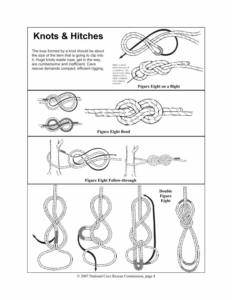
Knots & Hitches
The loop formed by a knot should be about the size of the item that is going to clip into it. Huge knots waste rope, get in the way, are cumbersome and inefficient. Cave rescue demands compact, efficient rigging.
Figure Eight on a Bight
Figure Eight Bend
Figure Eight Follow-through
Double Figure Eight
© 2007 National Cave Rescue Commission, page 2
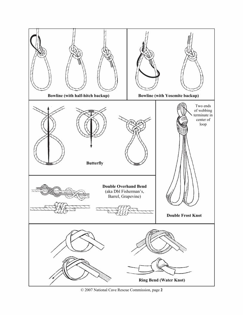
Bowline (with half-hitch backup) Bowline (with Yosemite backup)
Double Frost Knot
Two ends of webbing terminate in
center of loop
Double Overhand Bend (aka Dbl Fisherman’s,
Barrel, Grapevine)
Ring Bend (Water Knot)
Butterfly

© 2007 National Cave Rescue Commission, page 3
Trucker’s Hitch
A slip knot is commonly used to create the in-line loop, but for rescue work, a fixed loop is often preferable.
Trucker’s Hitch on slip knot
Trucker’s Hitch on fixed loop
(preferred for rescue)
Tied-Off Trucker’s Hitch
(backup not shown)
Tying a Trucker’s Hitch:
Step 1: Attached end of rope to an anchor or object (not shown) Step 2: Tie a loop (slip knot, butterfly, 8 or overhand bight, etc.) Step 3: Pass rope around or through an anchor/attachment point. Step 4: Thread end of rope through in-line bight. Pull to tighten. Configuration provides modest mechanical advantage and allows tension to be retained and secured. Step 5: Secure with a half-hitch on a bight, then back up with an overhand on the bight (backup not shown)
Münter Hitch (For one-person load belays)
Prusik Hitch Double-wrap (1-person loads)
Triple-wrap (rescue loads)
Clove Hitch (overhand backup)

© 2007 National Cave Rescue Commission, page 4
Anchoring
Tensionless Hitch (round turn)
Wrap 3, Pull 2 (webbing or rope)
Basket Rigging (knot at back)
Load Sharing Anchor System (fixed length legs). Appropriate for
Levels 1 and 2.
Girth Hitch (reduces rigging strength ~ 25%)
Load Distributing Anchor Systems (aka self-equalizing, self-adjusting) Failure of any one leg could lead to shock load and catastrophic failure of entire anchor system. Application of these techniques is a Level 3 skill.

© 2007 National Cave Rescue Commission, page 5
Pre-tensioned backtie is an adjustable stabilizer that utilizes mechanical advantage( typically 3:1)
The effective length of a pre-tensioned backtie may be extended by using a trucker’s hitch, but this
configuration will have more stretch under load than the full-length 3:1 version.
If the anchor for a backtie is not reasonably in line with the direction of
load, multiple backties will be necessary to stabilize focal point.
Backup Anchors
Pre-tensioned Backties
Backtie Anchors
Focal Point
Load
Load
Interlace Webbing
Focal Point
Tie off or secure with prusik hitch
Front rigging point is focal point, back-up is primary
anchor.
Backup using long-tail bowline
Backup using in-line figure
eight
Backup using double figure
eight

© 2007 National Cave Rescue Commission, page 6
Force Multiplication
Load
Resulting Force, Each Leg
Angle between
Legs
19
Deviation Forces
© 2007 National Cave Rescue Commission, page 7
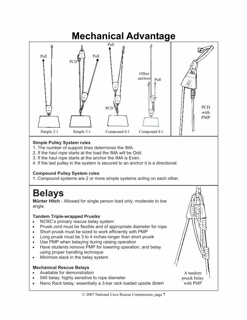
Belays Münter Hitch - Allowed for single person load only, moderate to low angle. Tandem Triple-wrapped Prusiks • NCRC’s primary rescue belay system • Prusik cord must be flexible and of appropriate diameter for rope • Short prusik must be sized to work efficiently with PMP • Long prusik must be 3 to 4 inches longer than short prusik • Use PMP when belaying during raising operation • Have students remove PMP for lowering operation, and belay
using proper handling technique • Minimize slack in the belay system Mechanical Rescue Belays • Available for demonstration • 540 belay: highly sensitive to rope diameter • Nano Rack belay: essentially a 3-bar rack loaded upside down
Simple Pulley System rules 1. The number of support lines determines the IMA. 2. If the haul rope starts at the load the IMA will be Odd. 3. If the haul rope starts at the anchor the IMA is Even. 4. If the last pulley in the system is secured to an anchor it is a directional. Compound Pulley System rules 1. Compound systems are 2 or more simple systems acting on each other.
Mechanical Advantage
A tandem prusik belay with PMP
PCD with PMP
Simple 2:1 Simple 3:1 Compound 4:1 Compound 4:1
PCD
Pull Pull
Pull
Pull Offset
anchors
PCD

© 2007 National Cave Rescue Commission, page 8
34
“Even” Hauling Systems
Anchor
To Load
PCD Option 1: between load and haul system
PCDAnchor
Haul rope fastened to
anchor
To Load
PCD Option 2: at anchor
“Odd” Hauling Systems
Anchor
To Load
Progress capture at anchor
PCD
Haul rope fastened to load

© 2007 National Cave Rescue Commission, page 9
Anchor
Tether
Second person for
counterweight
Fixed Line
Rappeller(using rack
on fixed line)
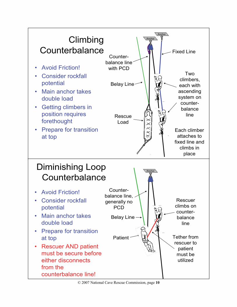
Rappelling Counterbalance
• Avoid Friction!• Consider rockfall
potential• Main anchor takes
double load• Prepare for transition
when load reaches top
Rescue Load
Belay Line
Counter-balance line
with PCD
Anchor
Anchor
One or more persons serve as a counterweight
Basics of Counterbalance Systems
Rescue Load
The counterbalance line runs from the load, through
a pulley, and back to the counterweight.
If the counterweight is heavier than the load, the load goes up and
the counterweight goes down!
The pulley provides a change of direction, but no
mechanical advantage
© 2007 National Cave Rescue Commission, page 10
Anchor
Rescuer climbs on counter-balance
line
Diminishing Loop Counterbalance
Patient
Belay Line
Counter-balance line, generally no
PCD
Tether from rescuer to
patient must be utilized
• Avoid Friction!• Consider rockfall
potential• Main anchor takes
double load• Prepare for transition
at top• Rescuer AND patient
must be secure before either disconnects from the counterbalance line!
18
Anchor
Anchor
Fixed Line
Two climbers, each with ascending system on counter-balance
line
Climbing Counterbalance
Rescue Load
Belay Line
Counter-balance line
with PCD
Each climber attaches to
fixed line and climbs in
place
• Avoid Friction!• Consider rockfall
potential• Main anchor takes
double load• Getting climbers in
position requires forethought
• Prepare for transition at top
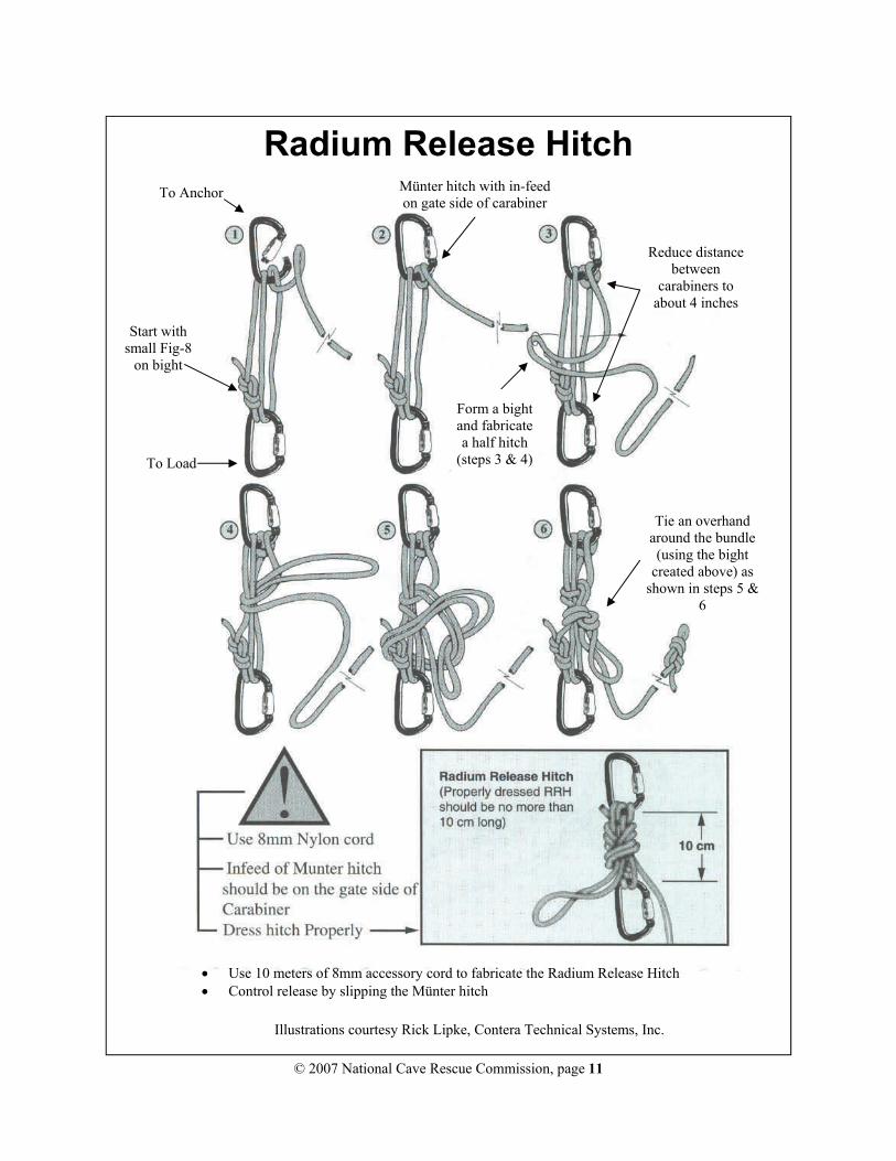
© 2007 National Cave Rescue Commission, page 11
Illustrations courtesy Rick Lipke, Contera Technical Systems, Inc.
To Anchor
To Load
Start with small Fig-8
on bight
Münter hitch with in-feed on gate side of carabiner
Reduce distance between
carabiners to about 4 inches
Form a bight and fabricate a half hitch
(steps 3 & 4)
Tie an overhand around the bundle (using the bight
created above) as shown in steps 5 &
6
• Use 10 meters of 8mm accessory cord to fabricate the Radium Release Hitch • Control release by slipping the Münter hitch
Radium Release Hitch

© 2007 National Cave Rescue Commission, page 12
Allowable focal point connections: long-tail butterflies or bowlines, not interlaced, long-tail bowlines, interlaced. Attaching
the lines without long tails (and using tethers for the attendant and patient con-nections) are allowed but discouraged.
Litter attendant clips to tail of mainline, moves up and down on ascending sys-tem, and clips to one spider leg using tether as second point of attachment.
Carabiner gates oriented in and down
End of belay line attaches to patient. Line passes through neck opening in packaging.
Litter Rigging
Litter Bridle
Fig 8 on bight, tied compact
Double overhand bend (better if tied on outside
of litter) Clove hitches
Rig short, bridle will stretch when loaded.

© 2007 National Cave Rescue Commission, page 13
NC
RC
Pac
kagi
ng w
ith D
oubl
e V
Res
trai
n Sy
stem
1: P
lace
tarp
ove
r litt
er,
offs
et to
one
sid
e2:
Pla
ce b
lank
ets
over
tarp
, of
fset
sim
ilarly
.3:
Pla
ce O
SS
(if n
eede
d) a
nd
seat
har
ness
on
pack
agin
g.
5: F
old
botto
m o
f tar
p an
d bl
anke
t ove
r fee
t. G
irth
hitc
h tw
o 20
’web
bing
sec
tions
to
harn
ess.
Atta
ch b
elay
teth
er.
6: S
ecur
e up
per w
ebbi
ng to
litte
r rig
ging
poi
nts
(snu
g, n
ot ti
ght),
th
en s
ecur
e lo
wer
web
bing
. Fol
d bl
anke
ts &
tarp
to e
ncas
e pa
tient
.
8: U
se li
tter r
estra
ints
or
web
bing
lash
ing
to s
ecur
e pa
tient
and
pac
kagi
ng in
litte
r.
9: B
lank
et ro
ll (s
ecur
ed w
ith ta
pe)
can
be u
sed
to in
sula
te p
atie
nt’s
he
ad. (
Not
e: s
pina
l sta
biliz
atio
n is
ac
hiev
ed w
ith O
SS
). P
rote
ct e
yes
with
gog
gles
or s
hiel
d. C
heck
ai
rway
, inj
urie
s, p
ress
ure
poin
ts.
7. S
uppo
rt
patie
nt w
ith
foot
loop
(or
foot
boa
rd)
and
knee
str
ap(a
bove
kne
e)w
hen
inju
ries
perm
it.
Avo
id
supp
ortin
g by
se
at h
arne
ss
whe
neve
r po
ssib
le.
OS
S om
itted
fo
r cl
arity
Tarp
om
itted
fo
r cla
rity
23M
ay/0
7 jw
p
4: P
lace
pat
ient
in li
tter,
secu
re
harn
ess
and
OSS
. Pad
und
er
knee
s, s
mal
l of b
ack,
nec
k –
as
appr
opria
te. I
f sup
port
ing
by s
eat
harn
ess,
pad
gro
in c
aref
ully
.

© 2007 National Cave Rescue Commission, page 14
Assessing System Safety Ratio
• Identify minimum breaking strength of each component, as configured in system
• Identify load experienced by each component in system, as configured
• Calculate component load ratio on each component (MBS/expected load)
• Lowest component load ratio (weakest link) is system load ratio
• Determine if this ratio is high enough to satisfy your safety criteria
NCRC System Safety Ratio
NCRC targets a minimum system safety ratio of 7:1
for its instructional events.