Embed Size (px)
Citation preview
Facsimile Communication over IP NetworksA Thesis Submittedin Partial Ful�llment of the Requirementsfor the Degree ofMaster of Technology
byB.V.S. Girish
to theDepartment of Computer Science & EngineeringIndian Institute of Technology, KanpurMarch, 1999

Certi�cateThis is to certify that the work contained in the thesis entitled \Facsimile Com-munication over IP Networks", by B.V.S. Girish, has been carried out under mysupervision and that this work has not been submitted elsewhere for a degree.March, 1999 (Dr. Dheeraj Sanghi)Assistant Professor,Department of Computer Science & Engineering,Indian Institute of Technology,Kanpur.

AcknowledgmentsI would like to express my profound gratitude to Dr. Dheeraj Sanghi for his supportand guidance throughout this work. I have had many opportunities to interact withhim right from my �rst semester. I thank him for all the valuable insights he hasgiven me throughout my M.Tech programme. I thank Dr. Rajat Moona for helpingme in the initial stages of my work. I would like to thank Dr. Sumit Ganguly forgiving me a PC for my exclusive use. Thanks Dr.TVP for lending me a much neededmodem.I would like to thank my senior Atul Kumar for taking his time to help me in manyways. Thanks to Shakti for helping me in getting the modem cable done. Thanksalso to Mr. Brahmaji for letting me share his telephone connection.My heart-felt thanks to Shanthi who took her time from busy hours for helpingme in searching the web when our Internet link was almost non-existent and for hervaluable suggestions. Thanks also to Sudev for his encouragement and prompt replyto my queries.I would also like to thank O. Ramakrishna, Sharad Gang, Manoj Bharadwaj andMr. Ramdas Baliga (SAS) who helped me in getting the reference materials. Thanksto Sowdhamini and Mr. Ashutosh (SAS) for giving me many valuable information.Many thanks to Rajesh Rajaram for his help and encouragement.I thank Gopi who shared lot of ideas and helped in the needed hours. I would alsolike to thank all my classmates especially Srikar, Prasanna, Uma, Varakkur, Subhash,Nihal and Atul who have made my stay here a memorable one.Kannada Sangha deserves a special mention. Thanks to all the members whomade our get-togethers an enjoyable one. I always looked forward to the deliciousand sumptuous meals that always accompanied our meetings. I am grateful to Prof.Raghavendra and Shantakka for the a�ection and hospitality bestowed on me. Thanks

also to Dr.T.K. Chandrashekar, Asha aunty, Prof. Prabhu, Mrs. Prabhu, Prof. NGRIyengar and Dr. Leela Iyengar for making me feel homely. Arvind, Katti, Puttaraju,Frederick, Karthik, Anand, Suresh and Narayana have given me a wonderful company.I am greatly indebted to Prof. Timothy Gonsalves who has been a source ofinspiration for me. I thank him for the support and encouragement he has alwaysgiven me.Finally, thanks to my parents, my brother, my sister and her family for the supportand encouragement that I always received.

AbstractCommunication over the packet-switched networks such as IP networks is farmore e�cient and cost-e�ective than the circuit-switched networks such as PSTN. Itis therefore desirable to use IP network as transport for circuit-switched applicationssuch as voice and facsimile. However, voice transport over IP network is common.In this work, we have designed and implemented a facsimile gateway for the trans-mission of facsimile documents between two standard terminal devices connected toa telephone network using the IP network for part of the communication path andbetween a terminal device connected to a telephone network and an electronic mailservice accesible via an IP network. Our design is based on the store-and-forwardmode of transmission in which the facsimile document does not reach the destinationbefore the sending terminal device terminates the facsimile call. So the sending ter-minal device will receive the con�rmation of delivery to the recipient in a separatefax transmission.

Contents1 Introduction 11.1 Traditional Fax . . . . . . . . . . . . . . . . . . . . . . . . . . . . . . 11.2 Internet Fax . . . . . . . . . . . . . . . . . . . . . . . . . . . . . . . . 21.2.1 Modes of Internet Fax . . . . . . . . . . . . . . . . . . . . . . 41.3 Need for Internet Fax . . . . . . . . . . . . . . . . . . . . . . . . . . . 51.4 Existing Fax Software . . . . . . . . . . . . . . . . . . . . . . . . . . 61.4.1 HylaFax . . . . . . . . . . . . . . . . . . . . . . . . . . . . . . 61.5 Scope of the Work . . . . . . . . . . . . . . . . . . . . . . . . . . . . 71.6 Organization of the Thesis . . . . . . . . . . . . . . . . . . . . . . . . 72 Background 92.1 Fax Transmission over PSTN . . . . . . . . . . . . . . . . . . . . . . 92.1.1 Fax Standards - Group 1, 2, 3, and 4 . . . . . . . . . . . . . . 92.1.2 Fax Transmission Protocol - T.30 . . . . . . . . . . . . . . . . 102.2 Image File Formats . . . . . . . . . . . . . . . . . . . . . . . . . . . . 172.2.1 File Format for Group 3 Terminals - T.4 . . . . . . . . . . . . 172.2.2 File Format for Internet Fax - TIFF . . . . . . . . . . . . . . . 192.3 Mail Transport over IP Networks . . . . . . . . . . . . . . . . . . . . 192.3.1 SMTP . . . . . . . . . . . . . . . . . . . . . . . . . . . . . . . 192.3.2 ESMTP . . . . . . . . . . . . . . . . . . . . . . . . . . . . . . 22i
2.3.3 MIME . . . . . . . . . . . . . . . . . . . . . . . . . . . . . . . 252.4 Modems . . . . . . . . . . . . . . . . . . . . . . . . . . . . . . . . . . 262.4.1 Modem Fax Classes . . . . . . . . . . . . . . . . . . . . . . . . 262.4.2 Host - Modem Communication . . . . . . . . . . . . . . . . . 273 Design of the Fax Gateway 283.1 PSTN Interface . . . . . . . . . . . . . . . . . . . . . . . . . . . . . . 283.1.1 State Diagram for Receiving . . . . . . . . . . . . . . . . . . . 293.1.2 State Diagram for Sending . . . . . . . . . . . . . . . . . . . . 313.2 SMTP Sender . . . . . . . . . . . . . . . . . . . . . . . . . . . . . . . 343.3 Onramp-O�ramp Communication . . . . . . . . . . . . . . . . . . . . 353.3.1 Message Format and Description . . . . . . . . . . . . . . . . 353.3.2 Onramp State Diagram . . . . . . . . . . . . . . . . . . . . . . 403.3.3 O�ramp State Diagram . . . . . . . . . . . . . . . . . . . . . 403.3.4 Timing Diagram . . . . . . . . . . . . . . . . . . . . . . . . . 413.4 Address Determination . . . . . . . . . . . . . . . . . . . . . . . . . . 423.4.1 IP Address Determination . . . . . . . . . . . . . . . . . . . . 443.4.2 Email Address Determination . . . . . . . . . . . . . . . . . . 463.5 Delivery Status Noti�cation . . . . . . . . . . . . . . . . . . . . . . . 473.5.1 Fax to Fax . . . . . . . . . . . . . . . . . . . . . . . . . . . . . 473.5.2 Fax to Email . . . . . . . . . . . . . . . . . . . . . . . . . . . 484 Implementation 494.1 Message Switch . . . . . . . . . . . . . . . . . . . . . . . . . . . . . . 494.2 PSTN Interface . . . . . . . . . . . . . . . . . . . . . . . . . . . . . . 514.3 SMTP Sender . . . . . . . . . . . . . . . . . . . . . . . . . . . . . . . 534.4 Onramp and O�ramp IP Interfaces . . . . . . . . . . . . . . . . . . . 544.5 Database Server . . . . . . . . . . . . . . . . . . . . . . . . . . . . . . 57ii

4.6 DSN Relay . . . . . . . . . . . . . . . . . . . . . . . . . . . . . . . . . 585 Conclusions 595.1 Future Work . . . . . . . . . . . . . . . . . . . . . . . . . . . . . . . . 59A Modem AT Commands 61Bibliography 64
iii

List of Figures1.1 Facsimile Transmission over IP . . . . . . . . . . . . . . . . . . . . . 82.1 Time sequence of a facsimile call . . . . . . . . . . . . . . . . . . . . . 112.2 Signal sequence . . . . . . . . . . . . . . . . . . . . . . . . . . . . . . 143.1 State Diagram for Receive . . . . . . . . . . . . . . . . . . . . . . . . 323.2 State Diagram for Sending . . . . . . . . . . . . . . . . . . . . . . . . 343.3 State Diagram for SMTP Sender . . . . . . . . . . . . . . . . . . . . 363.4 Message Format . . . . . . . . . . . . . . . . . . . . . . . . . . . . . . 363.5 Format of Connection Request . . . . . . . . . . . . . . . . . . . . . . 373.6 Format of Connection Response . . . . . . . . . . . . . . . . . . . . . 373.7 Format of Information message . . . . . . . . . . . . . . . . . . . . . 383.8 Format of Data Message . . . . . . . . . . . . . . . . . . . . . . . . . 383.9 Format of End of Page Message . . . . . . . . . . . . . . . . . . . . . 393.10 Format of End of Document Message . . . . . . . . . . . . . . . . . . 393.11 Format of Connection Release Message . . . . . . . . . . . . . . . . . 403.12 State Diagram for Onramp . . . . . . . . . . . . . . . . . . . . . . . . 413.13 State Diagram for O�ramp . . . . . . . . . . . . . . . . . . . . . . . . 423.14 Timing Diagram . . . . . . . . . . . . . . . . . . . . . . . . . . . . . 434.1 Interaction between the modules . . . . . . . . . . . . . . . . . . . . . 50
iv
Chapter 1Introduction1.1 Traditional FaxFacsimile (Fax) is an application for sending a document from one terminal deviceto another. Traditionally, the fax transmission occurs over telephone network. Intraditional facsimile (which refers to implementations of T.30 protocol [ITU96a]),communication over the telephone network is accomplished using modems (Section2.4). The transmission of data from one end to the other is preceded by negotiation ofcapabilities of the sender and the receiver (to ensure that the receiver can decode andrender the received document) and followed by con�rmation of delivery. Over time,there have been many extensions to the basic image model, to allow for additionalcompression methods and for representation of images with grey-scale and color.Other delivery extensions have included sub-addressing (additional signals after thecall is established to facilitate automated routing of faxes to desk-tops or mailboxes).Typically, the terminal device consists of a paper input device (scanner), a paperoutput device (printer), and (a limited amount of) processing power. Traditionalfacsimile has a simple user operational model. The sender1. inserts paper into a device,2. dials a number corresponding to the destination,3. presses the `start' button on the device,1

4. the sending device connects to the receiving device using the telephone network,5. the sending device scans the paper and transmits the image of the paper,6. the remote device receives the transmitted image and prints it on paper, and7. upon completion of transmission and successful processing by the recipient, thesender is noti�ed of success.The operation (5) of transmission consists of:5a. Negotiation: The capabilities of the sender and recipient the are exchanged, andsuitable mutually acceptable parameters for the communication are selected.5b. Scanning: Digitized images of pages of a document are created.5c. Compression: The image data is encoded using a data compression method.5d. Transmission: Data is sent from one terminal to the other.In addition, after the image data is sent, the operations consists of:i. completed delivery: the sending device indicates the completion of transmissionto the recipientii. completed receipt: the recipient receives the indication of message completionfrom the sending device,iii. processing and disposition: the recipient processes the message and generatesa signal to indicate to the sending device whether the document was receivedproperly.1.2 Internet FaxInternet Fax refers to a document transmission mechanism where at least part of thecommunication path is an IP Network. Communication might be between:2

� Two fax terminals, both connected to a telephone network with an IP networkin between. This requires use of a PSTN to IP (onramp) gateway and an IP toPSTN (o�ramp) gateway. For example, in Figure 1.1, the communication pathwould be:fax terminal F1 -> onramp gateway G1 -> offramp gateway G2 -> fax terminal F2.� A fax terminal and an Internet node such as email server or fax aware server.The initial part of the communication is over telephone network and the laterpart is over IP network. This requires an onramp gateway. For example, inFigure 1.1, the fax terminal F1 transmits the document to the onramp gatewayand based on the recipient information provided by the sender at F1, the onrampgateway transmits the document to the mail box of the recipient on host H1.fax terminal F1 -> onramp gateway G1 -> Mail box on host H1� An Internet node and a fax terminal. In this case, the initial part of the com-munication is over an IP network and the later part is over PSTN. This requiresan o�ramp gateway. For example, in Figure 1.1, email service on host H1 sendsa document to the o�ramp gateway G2 along with the destination fax num-ber. The o�ramp gateway dials the destination fax number and transmits thedocument to the recipient fax terminal F2.Email service on host H1 -> offramp gateway G2 -> fax terminal F2Operation (2) of the user operational model of fax could now be as follows:2a. Sender dials the number corresponding to the fax onramp gateway.2b. Onramp gateway answers the call and asks for the destination fax number.2c. Sender dials the destination fax number.2d. The onramp gateway determines the IP address of the server corresponding tothe fax number. It also determines whether the fax can be sent to an email boxinstead of a fax terminal (Section 3.4).3

2e. If the fax can be sent to an email box (e.g. to mail box on host H1 or G2 inFigure 1.1), the onramp gateway asks for the user-id. The sender can enter theuser-id, if known. The onramp gateway determines the email address (Section3.4.2) based on the information provided by the sender (fax number and user-id).2f. The onramp gateway now has speci�c information about the destination. If thedestination is a fax terminal or an email box, it asks the sender to proceed withthe fax transmission. If the destination cannot be reached (invalid fax numberor user-id), it terminates the connection.1.2.1 Modes of Internet FaxUnlike in traditional fax where there is a single mode of operation, fax over theInternet can occur in several modes [Mas97].� Real-Time Internet fax: This allows for two facsimile terminals conforming toT.30 protocol to engage in a document transmission in a way that all of theT.30 communication protocol is preserved, i.e., all the signals corresponding tothe T.30 protocol (for example, session establishment) are exchanged betweenthe two end terminals [Sil97].� Store-and-forward Internet fax: This entails a process of storing the entire doc-ument at an Internet host called a staging point (for example, an onramp or ano�ramp gateway), prior to transmitting it to the next staging point. Transfercan be directly between sender and recipient or there can be a series of interme-diary staging points. In Figure 1.1, the fax terminal F1 establishes a fax sessionand transmits the document to the onramp gateway G1. F1 gets a noti�cationthat the transmission to G1 was (un)successful. When G1 receives the com-plete document, it transmits the document to the o�ramp gateway G2. Uponcomplete reception of the document, G2 transmits it to the fax terminal F2.� Session Internet fax: In this mode of fax, the delivery noti�cation is providedto the transmitting terminal prior to disconnection. Unlike store-and-forward,there is an expectation that direct communication, negotiation, and retransmis-sion can take place between the two endpoints. But it is not necessary that the4

T.30 protocol be preserved end-to-end as in the case of real-time fax. In Figure1.1, the fax terminal F1 establishes a connection with the onramp gateway G1and G1 simultaneously establishes a connection with o�ramp gateway G2 whichin turn establishes a connection with the fax terminal F2. The T.30 protocolsignals need not necessarily be transmitted between the end terminals F1 andF2 unlike in real-time mode of fax. Prior to disconnection, F1 gets a noti�cationthat the transmission to F2 was (un)successful.1.3 Need for Internet FaxTraditional facsimile has proved to be a reliable application and is in widespread use.However, with the help of Internet, enhanced services can be provided at economicalcosts.� Traditional facsimile document transmission is very expensive especially overinternational long distances. The same document when transmitted over theInternet would cost very less.� Another example of enhanced service is that, the sender can send documents tomultiple recipients in a single transmission (using IP multicast). The recipientscan be Internet servers or traditional fax terminals.� With traditional fax, a Group 3 fax terminal (Section 2.1.1) cannot communi-cate with a Group 4 fax terminal. However, with Internet fax, this would bepossible by building gateways.The work in this direction has only started a few years back. A related area ofinterest is Internet Telephony which refers to the voice communication over the IPnetwork. Internet Telephony has been a topic of research for quite some time andmany commercial products are available which provide real-time voice communicationover the Internet.But Internet Telephony per se will not solve the Internet fax problems. Thereason being that, telephony requires protocols for the establishment and release ofconnections. Once the connection is established, the end users can carry out theconversation for an unspeci�ed amount of time. Any delay in the propagation of5

signals would only hamper the quality of the service. Since facsimile is basicallya telephony application, it involves the usual connection establishment and releasecommon to the telephony. But the additional task will be to exchange the documentsbased on a standard protocol and this involves strict protocol timings. Internet doesnot provide real-time guarantees. This creates a bottleneck for having a real-timefacsimile communication over the Internet. Any delay in the propagation of signalswould mean that the session would be abruptly terminated.1.4 Existing Fax SoftwareThere are many fax softwares based on client-server architecture which can send faxesover the PSTN network. Typically, the server receives documents from the clientsover the IP network for transmission to the fax terminal. Many email to fax gatewaysexist which transmit an email message received over the Internet to a fax terminalover the PSTN. Some fax softwares also route an incoming facsimile document froma fax terminal to an email box of the recipient in a limited environment (e.g. in thereceiving host or a domain). We brie y describe one of the existing fax softwares.1.4.1 HylaFaxHylaFAX is a facsimile system for UNIX systems. It supports:� sending facsimile,� receiving facsimile,� polled retrieval of facsimile, etc.Incoming facsimile are stored in a receiving area as TIFF (Section 2.2.2) �les andmay be automatically delivered by mail and/or printed. A fax server status programcan be used to monitor the send and receive queues, as well as the state of facsimileservers.The software is structured around a client-server architecture. Fax modems mayreside on a single machine on a network and clients can submit an outbound jobfrom any machine that can communicate with the machine on which the modems6

reside. Clients and server communicate over a protocol which is similar to FTP. Onecan also use standard FTP to communicate to the server directly. An access controlmechanism is included to control which users on which machines may submit jobs.Multiple modems on a single server machine are e�ectively scheduled for highthroughput. Support is provided for scheduling jobs during o�-peak hours based onthe destination phone numbers (e.g. long distance calls may be scheduled for o�-peakphone rates). An access control mechanism can be used to restrict the class of phonenumbers called.1.5 Scope of the WorkIn this thesis, we have designed and implemented the Onramp and the O�ramp faxgateways for store-and-forward mode of fax. The design provides for a Group 3 faxterminal to transmit documents to another Group 3 fax terminal any where in theworld. A Group 3 fax terminal can also transmit documents to an email box of oneor more recipients (Figure 1.1) using onramp gateway. For example, in Figure 1.1,the sender at fax terminal F1 will �rst transmit the document to the onramp gateway(G1) after providing the recipient information. Based on this information (like faxnumber or user-id), the G1 determines whether the recipient is a fax terminal or anemail box. G1 then transmits the document to the o�ramp gateway G2 for furthertransmission to F2 or to the host H1 for delivering to the mail box. The sender willget the Delivery Status Noti�cation indicating failure or success in a separate faxtransmission.We have implemented the design on the Linux Operating System. In the imple-mentation, we have assumed that the onramp fax gateway has the information aboutall the o�ramp fax gateways for IP Address determination (Section 3.4.1). We havealso assumed that the sender can transmit to only a single email recipient.1.6 Organization of the ThesisIn Chapter 2, we discuss related technologies. Traditional fax transmission is dis-cussed which includes a description of di�erent signals and the encoding scheme.Next, we discuss the mail transport over IP networks. Starting with the Simple Mail7

PSTN to IPOnrampGateway
Fax Terminal
SwitchPSTN
Fax Terminal
PSTNSwitch
PSTN line
Normal operation, through PSTN
PSTN line PSTN line PSTN line
IP to PSTN
Gateway
Host
Mail box
Mail box
Offramp
F1 G2
H1
F2
G1
IP Network
Figure 1.1: Facsimile Transmission over IPTransport Protocol (SMTP) [Pos82], we proceed to describe the extended version ofSMTP which is required for delivery noti�cations and Multipurpose Internet Mail Ex-tensions (MIME) [FB96a] which is required for encoding and sending the documentimage as an attachment.In Chapter 3, we present the design of the fax gateway that we have developed.We describe the design of various interfaces. Then we discuss a scheme for addressdetermination. Finally, we describe the delivery noti�cation method that we haveemployed.In Chapter 4, we discuss implementation of our design. We describe each of themodules and their interaction with each other.In Chapter 5, we present the conclusions and suggest future work.
8
Chapter 2Background2.1 Fax Transmission over PSTN2.1.1 Fax Standards - Group 1, 2, 3, and 4Fax standards have emerged from analog transmission units (Group 1,2) in the latesixties and early seventies to the digital transmission units (Group 3,4) in the eighties.The Group 3 facsimile standard however, has been in wide use for two decades now.The salient points about these standards are summarized below.� Group 1{ Became a standard in 1968 for analog facsimile devices to communicateover analog telephone lines.{ Unreliable, six minutes per page, poor resolution.{ The characteristics and operation of the facsimile devices conforms to theITU-T Recommendation T.2.� Group 2{ Became a standard in 1976 for analog facsimile devices to communicateover analog telephone lines.{ Worldwide compatibility. 9

{ Three minutes per page.{ The characteristics and operation of the facsimile devices conforms to theITU-T Recommendations T.30 and T.3.� Group 3{ Became a standard in 1980 for digital facsimile devices to communicateover analog telephone lines.{ Provides exibility to add innovative features without compromising basiccompatibility with standard Group 3 machines.{ 6 to 30 seconds per page, plus about 15 seconds for the �rst page initialhandshake.{ The characteristics and operation of the facsimile devices conforms to theITU-T Recommendations T.30 and T.4 [ITU96b].{ It is the current standard.� Group 4{ Became a standard in 1984 for digital facsimile devices to communicateover digital telephone lines.{ Designed for ISDN 64 kbps.{ The characteristics and operation of the facsimile devices conforms to theITU-T Recommendations T.563, T.503, T.521, T.6, T.62, T.70, T.72,T.411 to T.417.{ Incompatible with Group 3.2.1.2 Fax Transmission Protocol - T.30The T.30 Recommendation de�nes the procedures which are necessary for documenttransmission between two facsimile terminals in the public switched telephone net-work.These procedures essentially comprise the following �ve separate and consecutivephases as shown in Figure 2.1: 10

Phase A
In-messageprocedure
Message transmission
Facsimile procedure
Facsimile call
Phase BPhase C1
Phase C2Phase D Phase E
Call releaseCall estbl Pre-msg proc Post-msg proc
Figure 2.1: Time sequence of a facsimile callPhase A - Call establishmentCall establishment consists of establishing a connection between the calling and calledterminals and exchanging the fax tones. It can be realized manually and/or automat-ically.In manual operation at the calling terminal, the operator dials the number andhears the ringing tone. When the called terminal answers the call, the calling terminaloperator hears the fax tone immediately or can have a verbal exchange depending onwhether the called terminal answering is automatic or manual. The calling facsimileterminal is then switched to line which transmits the fax tone to the called terminal.In manual operation at the called terminal, the operator answers the call whenthe ring is heard. Depending on whether the calling terminal call establishment ismanual or automatic, the operator can have a verbal exchange or hears the callingfax tone. The operator then has to switch the facsimile terminal to line.In automatic operation at the calling terminal, the terminal detects the dial toneand dials the desired number. When the called terminal answers the call, the callingterminal immediately transmits a fax calling tone.In automatic operation at the called terminal, the terminal answers the call whenthere is an incoming ring and transmits the fax called tone immediately.11

Phase B - Pre-message procedureThe pre-message procedure consists of the identi�cation of capabilities and the com-manding of the chosen conditions as well as con�rmation of acceptable conditions.Identi�cation sectionThis consists of:� capabilities identi�cation. The called terminal sends this information to thecalling terminal. e.g. bit rate, page length and width, data compression format,scan time per line etc.� con�rmation for reception. The called terminal sends this message to the callingterminal.� terminal identi�cation (option). e.g. telephone number, name of the organiza-tion etc.� non-standard facilities identi�cation (option). e.g. for enhanced security.Command sectionThis consists of:� capabilities command for specifying the chosen (negotiated) capabilities basedon the identi�ed capabilities.� training which involves sending a series of 0s, to give an indication of the ac-ceptability of the channel for the chosen data rate.� synchronization of the calling and called terminal.Phase C1 - In-message procedureThe in-message procedure takes place at the same time as message transmission andcontrols the complete signalling for in-message procedure. i.e. the control signalsrequired for the transfer of the message are sent along with the message. e.g. in-message synchronization, error detection and correction and line supervision.12

Phase C2 - Message transmissionThe message transmission procedure is discussed in Recommendation T.4 which in-cludes coding scheme (Section 2.2.1), modulation and demodulation, etc.Phase D - Post-message procedureThe post-message procedure includes information regarding:� end-of-message signalling: This is sent by the calling terminal to indicate to thecalled terminal that all the pages in the document have been transmitted andto return to phase B for reception of another document.� multi-page signalling: This is sent by the calling terminal to indicate to thecalled terminal that a page of the document has been completely transmittedand to return to phase C for reception of the next page in the same document.� end-of-facsimile procedure signalling: This is sent by the calling terminal tothe called terminal to indicate that all the pages in the document have beencompletely transmitted and that no further documents are forthcoming and toproceed to phase E.� con�rmation signalling: This is sent by the called terminal to con�rm the receiptof the message in response to any of the above information sent by the callingterminal.Phase E - Call releaseThe calling terminal transmits a disconnect signal to the called terminal for the releaseof the call. No response is expected.SignallingThe signalling between the terminals uses the binary coded signalling system whichis based on a High Level Data Link Control (HDLC) format developed for datatransmission procedures. The basic HDLC structure consists of a number of frames,13

Calling transmitter
Phase A
Phase B
Phase D
Phase C
Capabilities identification
Training
Command information
Message
End of message
Message confirmation
(DIS)
(CFR)
(MCF)
(EOM)
(TCF)
(TSI, DCS)
(CSI)
Phase EDisconnect
Confirmation to receive
Called receiver
(Call setup)
(DCN)
Called terminal identification
Figure 2.2: Signal sequenceeach of which is subdivided into a number of �elds. It provides for frame labelling,error checking and con�rmation of correctly received information.T.30 recommendation provides for the called terminal to either transmit or re-ceive. Figure 2.2 shows the signal sequence when the called terminal is transmitting.We brie y describe some of the important message exchanged between the callingand called terminals.Initial Identi�cationThe following messages are sent from the called to the calling terminal.1. Digital Identi�cation Signal (DIS) - This is the capabilities identi�cation signaltransmitted by the called terminal to the calling terminal in phase B. Thisinformation helps the calling terminal to know the characteristics of the calledterminal and decide the capabilities parameters to be employed for the session.14

2. Called Subscriber Identi�cation (CSI) - This optional signal may be used to pro-vide the speci�c identity of the called subscriber by its international telephonenumber. This signal is sent by the called terminal in phase A.Command to receiveThese messages are sent from the transmitter to the receiver.1. Digital Command Signal (DCS) - This signal is in response to the DIS signalsent by the called terminal. This indicates the capabilities used in the session.2. Transmitting Subscriber Identi�cation (TSI) - This optional signal indicates theidenti�cation of the transmitting terminal. It may be used to provide additionalsecurity to the facsimile procedures.3. Sub-address (SUB) - This optional signal indicates that the information con-tained in this is a sub-address in the called subscribers domain. It may be usedto provide additional routing information in the facsimile procedure.4. Password (PWD) - This optional signal indicates that the information containedin this is a password for transmission.5. Training Check (TCF) - This is a training signal which is sent by the callingterminal to give an indication of the acceptability of the channel for the chosendata rate. Its format is a series of 0s for 1.5 seconds. No HDLC frame is requiredfor this command.Pre-message response signalsThese signals are sent from the receiver to the transmitter.1. Con�rmation To Receive (CFR) - This is in response to the training signal(TCF) from the called terminal con�rming that the entire pre-message pro-cedure has been completed and the message transmissions may commence inphase C.2. Failure To Train (FTT) - This is in response to the training signal (TCF)rejecting the training signal and requesting a retrain.15

Post-message commandsThese signals are sent from the transmitter to the receiver.1. End Of Message (EOM) - To indicate the end of a complete page of facsimileinformation and to return to the beginning of phase B.2. MultiPage Signal (MPS) - To indicate the end of a complete page of facsimileinformation and to return to the beginning of phase C.3. End Of Procedures (EOP) - To indicate the end of a complete page of facsimileinformation and to further indicate that no further documents are forthcomingand to proceed to phase E.Post-message responsesThese signals are sent from the receiver to the transmitter.1. Message Con�rmation (MCF) - To indicate that a complete message has beensatisfactorily received and that additional messages may follow. (This is apositive response to MPS, EOM, EOP.)2. Retrain Positive (RTP) - To indicate that a complete message has been receivedand that additional messages may follow after retransmission of training andcon�rmation to receive (CFR).3. Retrain Negative (RTN) - To indicate that the previous message has not beensatisfactorily received. However, further receptions may be possible, providedtraining is retransmitted.Other line control signalsThese signals are sent for the purpose of handling errors and controlling the stateof the line.1. Disconnect (DCN) - This command which is typically sent by the transmitterfor terminating the facsimile session, indicates the initiation of phase E (callrelease). This command requires no response.16

2. Command Repeat (CRP) - This optional response sent by the receiver indicatesthat the previous command was received in error and should be repeated in itsentirety. This is used only in the case of a pre-message (phase B) commandbeing received in error.2.2 Image File Formats2.2.1 File Format for Group 3 Terminals - T.4T.4 recommendation de�nes the characteristics of Group 3 facsimile terminals whichenable documents to be transmitted on the public switched telephone network. Theseterminals enable black and white documents to be transmitted and also colour docu-ments if the terminal conforms to the optional colour mode of the recommendation.The characteristics de�ned in this recommendation include dimensions (resolution,size of documents etc.) that the terminals should support, transmission time pertotal coded scan line (the sum of data bits, �ll bits and end-of-line bits constitute atotal coded scan line), coding scheme, modulation and demodulation among others.We brie y describe the coding scheme below.Coding SchemeT.4 recommendation describes many coding schemes. We brie y describe the codingscheme which is recommended for Group 3 terminals.One-dimensional Coding Scheme� Data: A line of data is composed of a series of variable length code words.Each code word represents a run-length of either all white or all black. Whiteruns and black runs alternate. A total of 1728 picture elements represent onehorizontal scan line of 215mm length.In order to ensure that the receiver maintains colour synchronization, all datalines will begin with a white run length code word. If the actual scan line beginswith a black run, a white run length of zero will be sent. Black and white run17

lengths, up to a maximum length of one scan line are de�ned by the code wordswhich are of two types - the terminating code words and the make-up codewords. Each code word is a unique sequence of bits. There is a terminatingcode word for each run length in the range of 0 to 63 pels (picture elements).However, a make-up code word is there for run lengths which are a multiple of64 up to a maximum run length of 1728 pels. Each run length is representedby either one terminating code word or one make-up code word followed by aterminating code word.Run lengths in the range of 0 to 63 pels are encoded with their appropriate ter-minating code word (code words are di�erent for black and white run lengths).Run lengths in the range 64 to 1728 pels are encoded �rst by the make-up codeword representing the run length which is equal to or shorter than that required.This is then followed by the terminating code word representing the di�erencebetween the required run length and the run length represented by the make-upcode.� End-of-line (EOL): This code word follows each line of data. It is a uniquecode word that can never be found within a valid line of data. Therefore,resynchronization after an error burst is possible. In addition, this signal willoccur prior to the �rst data line of a page.� Fill: A pause may be placed in the message ow by transmitting Fill. Fill maybe inserted between a line of Data and an EOL, but never within a line of Data.Fill must be added to ensure that the transmission time of Data, Fill and EOLis not less than the minimum transmission time of the total coded scan lineestablished in the pre-message control procedure. The maximum transmissiontime of Fill bits is less than 5 seconds.� Return To Control (RTC): The end of a document transmission is indicatedby sending six consecutive EOLs. Following the RTC signal, the transmitterwill send the post page message commands in the framed format and the datasignalling rate of the control signals de�ned Recommendation T.30.18

2.2.2 File Format for Internet Fax - TIFFThe Tag Image File Format (TIFF) [MZB+98] is used to represent the data contentand structure generated by the current suite of ITU-T Recommendations for Group3 facsimile.The TIFF-based �le format enables standardized messaging-based fax over theInternet. TIFF has historically been used for handling fax image �les in applicationssuch as store-and-forward messaging.TIFF provides a means for describing, storing and interchanging raster image data.A primary goal of TIFF is to provide a rich environment within which applicationscan exchange image data.2.3 Mail Transport over IP Networks2.3.1 SMTPThe Simple Mail Transfer Protocol (SMTP) [Pos82] is designed to provide a mailtransport service which is reliable and e�cient. SMTP generally uses the TCP/IPprotocol suite which provides reliable communication, for transmission of e-mails.The SMTP ModelThe SMTP design is based on the following model of communication: as result ofa user mail request, the sender-SMTP establishes a two-way transmission channelto a receiver-SMTP. The receiver-SMTP may be either the ultimate destination oran intermediate node. SMTP commands are generated by the sender-SMTP andsent to the receiver-SMTP. SMTP replies are sent from the receiver-SMTP to thesender-SMTP in response to the commands. The dialog is purposely lock-step, one-at-a-time.The SMTP provides mechanisms for the transmission of e-mail; directly from thesending user's host to the receiving user's host when the two host are connected tothe same transport service (IP network), or via one or more relay SMTP-servers whenthe source and destination hosts are not connected to the same transport service.19

To be able to provide the relay capability the SMTP-server must be supplied withthe name of the ultimate destination host as well as the destination mailbox name.When the same message is sent to multiple recipients the SMTP encourages thetransmission of only one copy of the data for all the recipients at the same destinationhost.Commands are not case sensitive. But this is not true of mailbox user names. Forsome hosts the user name is case sensitive, and SMTP implementations must takecare to preserve the case of user names as they appear in mailbox arguments. Hostnames are not case sensitive.The SMTP ProceduresThe basic procedure used in SMTP is described below.Mail transactionsThere are three steps to SMTP mail transactions. Once the transmission channelis established, the transaction is started with a MAIL command which provides senderidenti�cation. One or more RCPT commands follow which provides the receiverinformation. Then a DATA command gives the mail data. And �nally, the end ofmail data indicator con�rms the transaction.The �rst step in the procedure is the MAIL command. The <reverse-path>contains the source mailbox.MAIL FROM:<reverse-path> <CRLF>This command tells the SMTP-receiver that a new mail transaction is startingand to reset all its state tables and bu�ers of any previous transaction in the session,including any recipients or mail data. It gives the reverse-path which can be used toreport errors. If accepted, the receiver-SMTP returns an OK reply.The <reverse-path> can contain more than just a mailbox. The <reverse-path>can be a reverse source routing list of hosts and source mailbox. The �rst host in the<reverse-path> should be the host sending this command.The second step in the procedure is the RCPT command.20

RCPT TO:<forward-path> <CRLF>This command gives a forward-path identifying one recipient. If accepted, thereceiver-SMTP returns an OK reply, and stores the forward-path. If the recipient isunknown, the receiver-SMTP returns a Failure reply. This step can be repeated anynumber of times.The <forward-path> can contain more than just a mailbox. The <forward-path>is a source routing list of hosts and the destination mailbox. The �rst host in the<forward-path> should be the host receiving this command (receiver-SMTP).The third step in the procedure is the DATA command.DATA <CRLF>If accepted, the receiver-SMTP returns an Intermediate reply and considers allsucceeding lines to be the message text. When the end of text is received and storedthe SMTP-receiver sends an OK reply.Since the mail data is sent on the transmission channel, the end of the mail datamust be indicated so that the command and reply dialog can be resumed. SMTPindicates the end of the mail data by sending a line containing only a period. Themail data includes the memo header items such as Date, Subject, To, Cc, From.The end of mail data indicator also con�rms the mail transaction and tells thereceiver-SMTP to now process the stored recipients and mail data. If accepted, thereceiver-SMTP returns an OK reply. The DATA command should fail only if themail transaction was incomplete (for example, no recipients), or if resources are notavailable.Opening and ClosingAt the time the transmission channel is opened there is an exchange to ensurethat the hosts are communicating with the hosts they think they are.The following two commands are used in transmission channel opening and closing:HELO <domain> <CRLF>QUIT <CRLF>In the HELO command the host sending the command identi�es itself.21

2.3.2 ESMTPSMTP has provided a stable and e�ective method of mail transport. Nevertheless,the need for a number of protocol extensions has become evident. Rather than de-scribing these extensions as separate and haphazard entities, the Extended SMTP(ESMTP) [KFR+94] in a straightforward fashion provides a framework in which allfuture extensions can be built in a consistent way.Given this environment, the framework for the extensions consists of1. A new SMTP command2. A registry of SMTP service extensions3. Additional parameters to the SMTP, MAIL FROM and RCPT TO commandsThe EHLO commandA client SMTP supporting SMTP service extensions should start an SMTP ses-sion by issuing the EHLO command instead of the HELO command. If the SMTPserver supports the SMTP service extensions it will give a successful response. If theSMTP server does not support any SMTP service extensions it will generate an errorresponse.DSNThe SMTP protocol requires that an SMTP server provide noti�cation of deliveryfailure, if it determines that a message cannot be delivered to one or more recipients.These noti�cation messages are often insu�cient to diagnose problems, or even todetermine at which host or for which recipients a problem occurred. Moreover, thereis no noti�cation for the successful delivery. So there is a strong need for deliverystatus noti�cation (DSN) [Moo96] service for Internet mail.Such a service is provided by an extension to the SMTP protocol called the De-livery Status Noti�cation. Using this mechanism, an SMTP client may request thatan SMTP server issue or not issue a delivery status noti�cation (DSN) under certainconditions. 22

An SMTP client wishing to request a DSN for a message may issue the EHLOcommand to start an SMTP session, to determine if the server supports any of sev-eral service extensions. If the server gives a successful response, and the responseincludes the EHLO keyword DSN, then the Delivery Status Noti�cation extension issupported.Ordinarily, when an SMTP server returns a successful response to the RCPTcommand, it agrees to accept responsibility for either delivering the message to thenamed recipient, or sending a noti�cation to the sender of the message indicating thatdelivery has failed. However, an extended SMTP (ESMTP) server which implementsthis service extension will accept an extended RCPT command (described below)which alters the conditions for generation of delivery status noti�cations. The ESMTPclient may also request whether the entire contents of the original message should bereturned (as opposed to just the headers of that message), along with the DSN.In general, an ESMTP server which implements this service extension will prop-agate delivery status noti�cation requests when relaying mail to other SMTP-basedMail Transport Agents (MTA) which also support this extension, and makes a beste�ort to ensure that such requests are honored when messages are passed into otherenvironments.Additional parameters for RCPT and MAIL commandsThe extended RCPT and MAIL commands are issued by a client when it wishesto request a DSN from the server, for a particular recipient. The extended RCPT andMAIL commands are identical to the RCPT and MAIL commands of SMTP, exceptthat one or more of the following parameters appear after the sender or recipientaddress, respectively.The NOTIFY parameter of the ESMTP RCPT commandA RCPT command issued by a client may contain the optional esmtp- keywordNOTIFY, to specify the conditions under which the SMTP server should generateDSNs for that recipient. The value of this parameter can be NEVER, SUCCESS,FAILURE, DELAY.The meaning of the NOTIFY parameter values is generally as follows:23

� A NOTIFY parameter value of NEVER requests that a DSN not be returnedto the sender under any conditions.� A NOTIFY parameter value containing the SUCCESS or FAILURE keywordsrequests that a DSN be issued on successful delivery or delivery failure, respec-tively.� A NOTIFY parameter value containing the keyword DELAY indicates thesender's willingness to receive delayed DSNs. Delayed DSNs may be issuedby the MTA (at which the message is delayed) if delivery of a message hasbeen delayed for an unusual amount of time (as determined by the MTA). Butthe MTA still attempts for a particular amount of time to deliver the message.The absence of the DELAY keyword in a NOTIFY parameter requests that adelayed DSN not be issued under any conditions.The RET parameter of the ESMTP MAIL commandThe RET esmtp-keyword on the extended MAIL command speci�es whether ornot the message should be included in any failed DSN issued for this message trans-mission. If the RET esmtp-keyword is used, it must have an associated esmtp-value,which is one of the following keywords:� FULL requests that the entire message be returned in any failed delivery statusnoti�cation issued for this recipient.� HDRS requests that only the headers of the message be returned.If no RET parameter is supplied, the MTA may return either the headers of themessage or the entire message for any DSN containing indication of failed deliveries.The ENVID parameter to the ESMTP MAIL commandThe ENVID esmtp-keyword of the SMTP MAIL command is used to specify anenvelope identi�er to be transmitted along with the message and included in anyDSNs issued for any of the recipients named in this SMTP transaction. The purposeof the envelope identi�er is to allow the sender of a message to identify the transactionfor which the DSN was issued. 24

The ENVID esmtp-keyword must have an associated esmtp-value. No meaningis assigned by the mail system to the presence or absence of this parameter or toany esmtp-value associated with this parameter; the information is used only by thesender or his user agent.2.3.3 MIMEOne of the notable limitations of RFC 821/822 based mail systems is the fact thatthey limit the length of the text lines to 1000 characters of 7bit US-ASCII. This forcesusers to convert any non-textual data that they may wish to send into seven-bit bytesrepresentable as printable US-ASCII characters before invoking a local mail UA (UserAgent, a program with which human users send and receive mail). Examples of suchencodings currently used in the Internet include pure hexadecimal, uuencode, the3-in-4 base 64 scheme speci�ed in RFC 1421, and many others. Another limitationis that, RFC 822 does not specify a format for non-text messages such as audio orimages. It also does not support the use of character sets richer than US-ASCII. Soadditional speci�cations are needed.The Multipurpose Internet Mail Extensions (MIME) [FB96a, FB96b] describesseveral mechanisms that combine to solve most of these problems without introduc-ing any serious incompatibilities with the existing mail standards. In particular, itdescribes:1. A MIME-Version header �eld, which uses a version number to declare a messageto be conformant with MIME and allows mail processing agents to distinguishbetween such messages and those generated by older or non-conformant soft-ware, which are presumed to lack such a �eld. For example,MIME-Version: 1.02. A Content-Type header �eld, generalized from RFC 1049, which can be usedto specify the media type and subtype of data in the body of a message andto fully specify the native representation (canonical form) of such data. Forexample, Content-type: text/plain; charset="us-ascii"25

3. A Content-Transfer-Encoding header �eld, which can be used to specify boththe encoding transformation that was applied to the body and the domain ofthe result. Encoding transformations other than the identity transformationare usually applied to data in order to allow it to pass through mail transportmechanisms which may have data or character set limitations. For example,Content-transfer-encoding: base644. Two additional header �elds that can be used to further describe the data in abody, the Content-ID and Content-Description header �elds.2.4 ModemsA modem is a device that modulates data from digital signals to analog signals andvice-versa (e.g. modem used with PCs for dial-up connections). Since fax machinesalso need to transmit and receive digital data over the analog PSTN, there are ded-icated modems inside fax machines called fax modems. Data/Fax modems are typ-ically used with personal computers and can handle both data and fax information.The data is modulated in a standard format on an voice band carrier for transmissionover the telephone network. The analog signals are then converted back into digitaldata by the receiving modem (demodulation). Di�erent standards are used for faxand data.2.4.1 Modem Fax ClassesA modem typically has one or more classes of operation. A class 0 modem (or modemcon�gured to class 0) behaves as a data modem. Class 1 and class 2 modems supportfax. With a class 1 fax modem, the software running on the host should handle allof the T.4 fax image and T.30 session protocol information and timing. Thus, theability to communicate properly is a function of the software. With a Class 2 faxmodem, the host software should generate a T.4 fax page image and send it to thefax modem a page at a time. The fax modem then handles the T.30 session protocolinformation and timing. This relieves the computer's CPU from some work. Theability to communicate is more a function of the fax modem than the software. It isto be noted that the T.30 protocol is also implemented partially on the host.26
2.4.2 Host - Modem CommunicationThe communication between the host and the modem is achieved through the useof a set of commands known as `AT' (attention) commands [Cir95]. The host sendsthese AT commands to the modem and the modem provides status information tothe host in the form of response codes. The modem contains several storage locationscalled S-registers. The contents of the S-registers can be modi�ed by using the ATcommands. The behaviour of the modem is directed by the contents of the S-registersas well as directly by the AT commands.All the commands sent to the modemmust be preceded by an `AT' and terminatedby a carriage return <CR> (contents of S-register S3). The AT commands used forclass 2 modem and the response codes are listed in Appendix A. After sending anAT command string to the modem, the host must wait for a response code from themodem before sending a new AT command string to the modem. For example,� ATDT597646<CR> directs the modem to dial the number 597646 in tonemode.Here, D is the command to dial and T is the dial modi�er to dial in tone mode.� ATS1?<CR> is the command to read the contents of the S-register S1. Themodem responds by providing the value contained in this register and the OKresponse code.� ATS0=3<CR> is the command to modify the contents of the S-register S0 tothe value 3. The modem responds with an OK response code. The contentsof this register, n, directs the modem to answer the call automatically after nrings.
27
Chapter 3Design of the Fax GatewayA fax gateway is a service which acts as an interface to transfer facsimile documentsbetween PSTN and IP networks. This gateway is connected on one side to PSTNand on the other side to an IP network. For a particular session of fax transmission,based on the function that a gateway performs, it can be classi�ed as� Onramp fax gateway: This is a service that can accept an incoming facsimilecall from PSTN and forward the facsimile document via the Internet to anyInternet service or node (including the fax o�ramp gateway).� O�ramp fax gateway: This is a service that can accept a facsimile document ora document intended for a fax terminal from the Internet and forward it to atraditional fax terminal over the PSTN.Our design of the fax gateway consists of an interface to the PSTN network andtwo interfaces to the IP network, one of them is the mail transport system (SMTPSender) for routing the fax document to an email box of the intended recipient andthe other is the interface to communicate with the peer gateway (Onramp/O�rampIP Interfaces) for routing the fax document to the destination fax terminal.3.1 PSTN InterfaceThe primary function of this interface is to send and receive the fax documents froma fax terminal over a PSTN connection. The other necessary functions are:28

� Determining the IP address and Email address (optionally) based on the des-tination fax number and user-id if given by the sender. The actual task ofdetermination is done by a di�erent service (Section 3.4.1), but this modulewill send a request and wait for a successful response before proceeding withthe fax transmission session with the sending fax terminal. In case no responseis obtained or a negative response arrives, the fax session is aborted and a mes-sage to this e�ect is given to the sender prior to disconnection. This is applicableto the onramp gateway.� Sending a Delivery Status Noti�cation (Section 3.5) to the sender to indicatewhether the delivery to the destination fax terminal was successful or not. Thisis applicable to the o�ramp gateway.This module is designed for communicating with a Fax Class 2 modem. Sincethe T.30 protocol is primarily handled by the modem and partially by the host, thestates, phases A through E in the host state diagrams (Figures 3.2 and 3.2) do notcorrespond to the T.30 phases.3.1.1 State Diagram for ReceivingTo begin with, the host waits in the IDLE state for the modem to give an indication ofRING when there is an incoming facsimile call (Figure 3.1). When there is a RINGindication, the host commands the modem to answer the call in the voice mode(#VLN=1). After the call is answered, host enters the ANSWERED state and thesender has to be given a voice message for dialing the fax number of the destinationfax terminal. This fax number is used for IP address determination of the o�rampgateway or of the server for determining the Email address. If required, the sendercan be given another voice message for dialing the user-id if the facsimile documenthas to be routed to an email box. When the required details for transmitting thedocument to the recipient have been obtained, the sender is signalled to enter intofacsimile mode (e.g. a message can instruct the sender to press the `Start' button onthe fax terminal). In case the sender fails to give the required information or if thegiven information is insu�cient or invalid, then the host should instruct the modemto hang up and should go to the IDLE state.Once the required information has been obtained, the host issues the Fax Answer29
command (ATA) to the modem and enters the PHASE A state. Upon receipt of anAnswer command from the host, the modem answers and generates the called fax(CED) tone. The modem then generates a DIS frame (Section 2.1.2) to send thereceiver (modem) capabilities to the sender and hunts for the �rst T.30 negotiationframes. Upon detection of the �rst Phase B preamble, it reports the fax connectionresponse (+FCON) message to the host. The host then enters the PHASE B state.In this state, the host should receive the transmit station id (via the +FTSI:<id>response) and the current session results i.e. the capabilities that will be used for thesession (via the +FDCS:<val> response) from the modem when it receives the T.30TSI and DCS frames respectively from the sender.When this is followed by OK response from the modem, the host issues the DataReceive (+FDR) command to the modem and enters PHASE C state to receive thedata. The modem indicates the con�rmation to receive (+FCFR) and when it isready to commence the data transfer, it issues a CONNECT message. When the hostis ready to accept data, it signals the modem to start sending the received data to thehost by issuing a <DC2> character (022) to the modem. The data received by themodem might contain special characters (e.g. control characters such as CANCEL<CAN>). For every occurrence of these characters, the modem pre�xes an escapecharacter (ASCII DLE character). When the host receives the data, it should destu�these escape characters. When the modem delivers the last byte of a page, it sends acharacter pair (<DLE><ETX>) to indicate the end of data stream and reports thePage Transfer Status (via the +FPTS:<ppr> response) which is actually the postpage response (ppr) message generated by the modem. The ppr value indicates thequality of the received page. This is followed by a post page message from the remotefacsimile station (via the +FET:<ppm> response) which signals the intentions of theremote station. The host now enters the PHASE D state.If the post page message (ppm) value indicates there are more pages in the samedocument, the host issues Data Receive (+FDR) command and enters PHASE C datareceive state. If the indication is that there are more documents, it enters PHASE Bstate. If there are no more pages or documents, then the host issues a Data Receive(+FDR) command and enters PHASE E state.The modem holds the post page response message (ppr) to the remote facsimilestation (MCF signal) (represented in the +FPTS parameter) until the next Data Re-ceive (+FDR) command. The host may modify the pprm (+FPTS parameter) before30

issuing the Data Receive command which releases that message. So the host mustissue a Data Receive command to release Post Page Response Messages irrespectiveof the post page message value.In the PHASE E state, the host issues a Session Termination (+FK) command tothe modem to terminate the session. In particular, the modem will send a Disconnect(T.30 DCN signal) message at the next opportunity and returns an OK message. Thehost should then issue a Hangup command and the modem will respond with an OKmessage. The host now enters the IDLE state and waits for another RING.Whenever there is an irrecoverable error or if the modem indicates an ERRORmessage, then the host should enter PHASE E state for an orderly termination of thesession.Escape from Data ReceptionFrom the reception of <DC2> character from the host until the end of Phase CData, the modem is in a data transfer state, and will not respond to host commandcharacters. The modem will respond to three ASCII control characters: <DC1>(017) and <DC3> (019) ow control characters, and cancel <CAN> (024) character.Upon receipt of the <CAN> character from the host, the modem will terminatethe reporting of received data by sending trailing end of data stream (<DLE><ETX>)characters to the host, and will then execute an implied Session Termination (+FK)command in order to conduct an orderly disconnection. The host goes to the IDLEstate.3.1.2 State Diagram for SendingWhen a facsimile document has to be transmitted to a fax terminal, the host in theIDLE state should give a dial command (ATD) immedialtely followed by the faxnumber to the modem (Figure 3.2). It should then enter the PHASE A state. Ifthis command is unsuccessful, the modem reports an appropriate failure or error typeresponse such as NO CARRIER, NO DIALTONE, or BUSY. If this call is successful,the modem detects the call progress, and generates the calling (CNG) tone. It thenwaits for a DIS frame which indicates the receiver capabilities. On detection of the�rst Phase B preamble, it reports the fax connection response (+FCON) message to31

PHASE D
IDLE
PHASE E
PHASE CPHASE Bmodem: OK
val = MORE_DOCS
modem: OK
PHASE A
ANSWERED
modem: ERROR
(CNG tone not detected)
modem: RING
modem
: Fax_Conn_Resp
(+FCON
) (+FDR)
mod
em: P
ost_
page
_Msg
(+
FET:
<val
>)
(val=END_OF_DOC)
(train
ing un
succ
essful
)
modem
: ERROR
Timeout
Rcv
: Rem
ote
num
ber
Host: Data_Rcv
Host: Data_Rcv
Host: Data_Rcv
Host: ANSWER
Host: <C
AN
>
Hos
t: Fa
x A
nsw
er
(
AT
A)
(val
=MO
RE_
PAG
ES)
Hos
t: D
ata_
Rcv
Host: Hangup (ATH)
modem: OKHost: Session_Term
Figure 3.1: State Diagram for Receivingthe host. The host then changes the state to PHASE B.The modem reports the called station id (via +FCSI:) and the called station capa-bilities (via +FDIS:) and this is followed by the OK message. The modem generatesa DCS frame which indicates the session capabilities, based on the received DIS frameand on the previously set capabilities (set via +FDCC:<capabilities string> duringmodem initialization) parameter. The host should issue a Data Transmit (+FDT)command which releases the modem to transmit that DCS frame. The modem re-ports the negotiated capabilities (DCS) to the host and gives a CONNECT message.The host now changes over to the PHASE C data transmission state.When the modem is ready to accept the data, it signal the host to start sendingthe data by sending a <DC1> character (021) to the host and waits for the data. Thehost sends the data in the stream mode and should terminate the data with an endof data stream (<DLE><ETX>) character pair. If any special characters occur inthe data, the host should pre�x it with the escape character (ASCII DLE character).32

The modem will acknowledge the end of the data by returning the OK message to thehost. The host should then issue a post page message (+FET=<ppm>) command tothe modem and enter PHASE D.The post page message (ppm) command indicates that the current page is completeand no more data will be appended to it. The ppm value indicates whether there areany additional pages that are to be sent and, if so, whether there is a change inany of the document parameters. The remote facsimile station should respond tothe post page message with a post page response. The modem reports this (via the+FPTS:<ppr> response) followed by an OK message. If there are more pages tobe sent in the current document, the host should issue a Data Transmit (+FDT)command and when the modem responds with a CONNECT message, it shouldchange the state to PHASE C data transmission. If a new document has to be sentwith re-negotiation of capabilities, the host should enter the PHASE B state. If thereare no more pages or documents, then the host should enter the PHASE E state forsession termination.In the PHASE E state, the host issues the Session Termination (+FK) commandfor an orderly termination of the session. When the modem responds with an OKmessage, the host should give the Hang up (ATH) command and go to the IDLEstate.Whenever there is an irrecoverable error or if the modem indicates an ERRORmessage, then the host should enter PHASE E state for an orderly termination of thesession.Escape from TransmissionThe modem may request the host to halt Phase C transmission, by sending a cancel<CAN> character (024) to the host. In this case, the host should terminate PhaseC transmission, issue <CAN>, and wait for the OK response from the modem. Thehost should then go to the IDLE state.33
IDLE
PHASE A
PHASE B
PHASE C
PHASE E
PHASE D
modem: CONNECT
modem: C
ONNECT
mod
em: <
CA
N>
(fax tone not detected)
modem: ERROR
modem: ERROR
(negotiation failure)
val=MORE_DOCS
(+FDT)
modem: Post_Page_Msg_Rsp
modem: OK
Host: Data_Tx
Host: Hangup (ATH)
Host: Data_Tx
Host: Dial (A
TD<num>)
mod
em: F
ax_C
onn
(+FC
ON
)
Host: Post_
Page_Msg
(+
FET=<val>)
modem: O
Kval=MORE_PAGESHost: Data_Tx
(+FPTS:)val=END_OF_DOCS
Host: Session_Term (+FK)
modem: OK
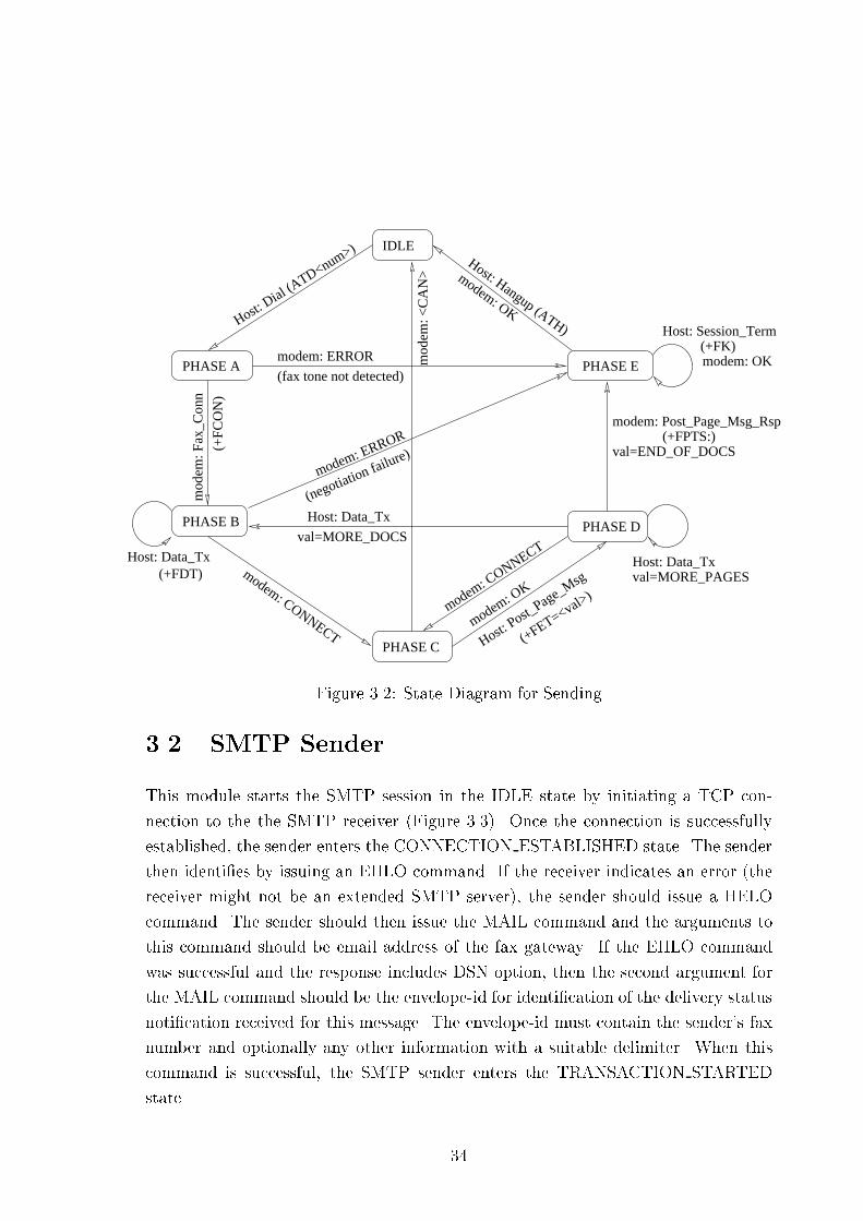
Figure 3.2: State Diagram for Sending3.2 SMTP SenderThis module starts the SMTP session in the IDLE state by initiating a TCP con-nection to the the SMTP receiver (Figure 3.3). Once the connection is successfullyestablished, the sender enters the CONNECTION ESTABLISHED state. The senderthen identi�es by issuing an EHLO command. If the receiver indicates an error (thereceiver might not be an extended SMTP server), the sender should issue a HELOcommand. The sender should then issue the MAIL command and the arguments tothis command should be email address of the fax gateway. If the EHLO commandwas successful and the response includes DSN option, then the second argument forthe MAIL command should be the envelope-id for identi�cation of the delivery statusnoti�cation received for this message. The envelope-id must contain the sender's faxnumber and optionally any other information with a suitable delimiter. When thiscommand is successful, the SMTP sender enters the TRANSACTION STARTEDstate. 34

In this state the sender can send the recipient information via the RCPT com-mand. The �rst argument to this command should be the recipient's email address.If the EHLO command was successful and the receiver SMTP supports DSN, thenthe second argument should be the NOTIFY parameter with values set to both SUC-CESS and FAILURE. The RCPT command should be issued individually for all therecipients. When atleast one of the recipient information is accepted, the sendershould issue the DATA command. If none of the recipient information is acceptedor if the DATA command fails, then the sender should issue a QUIT command toterminate the session, close the TCP connection and should enter the IDLE state.If the DATA command is successful, then the sender enters the DATA TRANSFERstate.In this state, the sender should �rst send the header information including theMIME headers for sending the image as an attachment. It should then send the bodyof the message. Each page of the facsimile document should be converted to TIFF andencoded using the Base64 encoding method. Each of these encoded pages should ap-pear as an attachment in a single email message. When all the data has been sent, thesender should indicate the end of data and enter the CONNECTION ESTABLISHEDstate.The sender can now choose to start another transaction with the same SMTPreceiver or can close the session by issuing a QUIT command and closing the TCPconnection. The sender now goes back to the IDLE state.3.3 Onramp-O�ramp CommunicationThe communication protocol between onramp and o�ramp gateways utilizes theTCP/IP protocol suite. The use of TCP is suitable because there is no real-timerequirements for the document transfer. The Onramp service should provide forre-attempts for the transmission of the document.3.3.1 Message Format and DescriptionThe message format consists of 4 octets of header and a variable length data as shownin the Figure 3.4. 35

CONN_ESTBLSHD
TRANSACTIONSTARTED
DATA_TRANSFER
INITIAL
sender: HELO, RCPT, NOOP
sender: DATA
sender: <data>
sender: QUIT
open_connectionsender: sender: QUIT
sender: HELO, NOOP
send
er: M
AIL
send
er: R
SET
sender: END_OF_DATA
indicator
Figure 3.3: State Diagram for SMTP Sendermsg_type
msg data
4
Pad msg length 4 Octets
512 Octets
1
Figure 3.4: Message FormatMessage TypesFor the state transitions described in the following messages, please refer to the Fig-ures 3.12 and 3.13 for onramp and o�ramp gateways respectively.� CONN REQ: This message is sent by the onramp gateway when it is in theIDLE state to the o�ramp gateway for establishing the connection on top of36

the TCP connection. The onramp gateway should then enter the CONNEC-TION PENDING state. The format of this message is shown in Figure 3.5.4
Pad
2
Onramp Fax Number
Onramp IP Address 16 Octets
4 Octets
16 Octets
Data length = 32
1
CON_REQ
Figure 3.5: Format of Connection Request� CONN RESP: When the o�ramp gateway receives the CONN REQ from theonramp gateway, it should check the resource availability and if it can accept theconnection, it should send the CONN RESP message to the onramp gateway.The o�ramp gateway should then go to the CONNECTION ESTABLISHEDstate and wait for further messages from the onramp gateway. The o�rampgateway should be concurrent to support multiple sessions with di�erent on-ramp gateways at the same time. When the onramp gateway receives theCONN RESP from the o�ramp gateway while in CONNECTION PENDINGstate, it should enter the CONNECTION ESTABLISHED state. The formatof this message is shown in Figure 3.6.4
Pad
2
Offramp Fax Number
Offramp IP Address 16 Octets
4 OctetsCON_RESP
16 Octets
Data length = 32
1
Figure 3.6: Format of Connection Response� INFO: In the CONNECTION ESTABLISHED state, the onramp gateway shouldsend the information related to the session using this message. It then entersthe INFO SENT state. Figure 3.7 shows the format of this message.37

4
Pad Data length
2
INFO 4 Octets
Sender Fax Number
Destination Fax Number
Doc Type Pad 4 Octets
16 Octets
16 Octets
= 36
1
Figure 3.7: Format of Information message� ACCEPT/REJECT: Upon receipt of the INFO message, the o�ramp gatewayshould determine whether the destination fax number comes within its ser-vice area and is permitted to transfer the document to the destination overthe telephone network. If it can, it should send an ACCEPT message tothe onramp gateway and enter the DATA RECV state and wait for the datatransfer. If it cannot handle the request, it should send a REJECT messageand wait for further messages from the onramp gateway in the CONNEC-TION ESTABLISHED state. When the onramp gateway receives the REJECTmessage, if there are other documents to be sent, then it can enter the CON-NECTION ESTABLISHED state otherwise, it should send a CONN RELEASEmessage and enter the RELEASE PENDING state.� DATA: When the onramp gateway receives the ACCEPT message from theo�ramp gateway, it should enter the DATA TRANSFER state. It can nowstart the data transfer. The data should be sent in this message. Since thedefault MSS (maximum segment size) value of TCP is 536 octets [Ste96], thedata length in each message can be chosen to be 512 octets. Figure 3.8 showsthe format of this message.4
Pad Data length
2
DATA 4 Octets
Fax Data
1
Figure 3.8: Format of Data Message38

� EOP: When the onramp gateway has completed transmitting a page, it shouldsend a EOP (End Of Page) message to the o�ramp gateway. This messagecontains the length of the page that was transmitted. The format of this messageis shown in Figure 3.9.4
Pad Data length
2
EOP
Page length sent
4 Octets
4 Octets
= 4
1
Figure 3.9: Format of End of Page Message� EOP ACK: This message is sent by the o�ramp gateway when it receives anEOP message. The o�ramp gateway should check the page length value in theEOP message with its own received length and report an EOP ACK messageto the onramp gateway.� EOD: When the onramp gateway has completed the document transmission,it should send EOD (End of Document) message to the o�ramp gateway. Thelength �eld should be set to the total length of the document sent. The formatof this message is shown in Figure 3.10.4
Pad Data length
2
EOD 4 Octets
4 OctetsDocument length sent
= 4
1
Figure 3.10: Format of End of Document Message� EOD ACK: When the o�ramp gateway receives the EOD message, it shouldcheck the total length of the document received with the value in the EODmessage. It should send the this message to acknowledge the end of documentand an indication about the document status. The o�ramp gateway should nowenter the DOC RECVD state.� CONN RELEASE:When the onramp gateway receives the EOD ACK message,it can send the CONN RELEASE message and enter the RELEASE PENDING39

state. It can also start another transaction by sending the INFO message andentering the INFO SENT state. The format of this message is shown in Figure3.11.4
Pad Data length
2
RELEASE 4 Octets
4 OctetsReason Pad
= 4
1
Figure 3.11: Format of Connection Release Message� CONN RELEASE COM: Upon receipt of the CONN RELEASE message, theo�ramp or the onramp gateway should send a CONN RELEASE COM messageand go to the IDLE state.The state transitions which occurs upon the receipt or sending of a message issummarized in the following state diagrams.3.3.2 Onramp State DiagramThe onramp state diagram is shown in Figure 3.12. In any state other than IDLE, ifthe onramp gateway receives a CONN RELEASE COM message, it should go to theIDLE state.Whenever any message other than DATA is sent by the onramp gateway, it shouldstart a timer whose value is MESSAGE RESPONSE TIMOUT. Upon the expiry ofthis timer, it should send a CONN RELEASE COM to abort the session and go tothe IDLE state.3.3.3 O�ramp State DiagramThe o�ramp state diagram is shown in Figure 3.13. The o�ramp gateway can alsoinitiate the session termination by sending a CONN RELEASE message while inDOC RECVD state, if it cannot accept further transactions or in any other stateother than IDLE and RELEASE PENDING states in exceptional cases.40

IDLE
CONNECTIONPENDING
CONNECTIONESTABLISHED
TRANSACTIONINFO_SENT
DATATRANSFER
RELEASEPENDING
sess
ion
abor
ted
snd: CONN_REQ
session aborted
rcv:
CO
NN
_RE
SP
sess
ion
abor
ted
rcv:
ACCEPT
rcv:
EOD_A
CK
snd:
INFO
session aborted
rcv: RELEASE_COM
snd:
RE
LE
ASE sn
d: R
EL
EA
SE
rcv:
EO
D_A
CK
rcv: REJECTsnd: INFO
snd: DATA ,EOP, EOD
rcv: EOP_ACK
Figure 3.12: State Diagram for OnrampWhenever the o�ramp gateway starts waiting for the data from the onramp gate-way, it should start a timer whose value is READ MESSAGE TIMER. Upon theexpiry of this timer, it should send a CONN RELEASE COM to abort the sessionand go to the IDLE state.3.3.4 Timing DiagramThe time-line of a document transfer between the onramp and o�ramp gateways in anormal case is shown in Figure 3.14. The document contains two pages. The statescorresponding to the onramp and the o�ramp gateways is shown on the respectivesides.41

RELEASEPENDING
DOC_RCVD
ESTABLISHEDCONNECTION
rcv: INFOsnd: REJECT
snd:
RE
LE
ASE
rcv: INFOsnd: REJECT
snd: RELEASE_COMrcv: CONN_REQ
rcv: EOPsnd: EOP_ACK
DATA_RCV
IDLE
rcv: INFO
snd: ACCEPT
snd:
CONN_RESP
rcv: C
ONN_REQ
snd: EOD_ACKrcv: EOD
snd: ACCEPTrcv: INFO
rcv: RELEASE
snd: RELASE_CO
Mrcv: RELEASE_COM
Figure 3.13: State Diagram for O�ramp3.4 Address DeterminationThe incoming facsimile document can be routed to another group 3 fax terminal orto an email box of the recipient.The fax has to be routed to the fax terminal through an o�ramp gateway. However,to route the document to an email box, the minimum service that is necessary is adatabase service to lookup the email address of the recipient with an user-id or afax number as the key. This service can be a part of the o�ramp gateway or canbe stand-alone. The onramp gateway determines the IP address based on the faxnumber. The IP address thus obtained corresponds to the host on which the o�rampgateway or the email address lookup service (or both) is available. If the documenthas to be routed to an email box, the onramp gateway determines the email addressfrom the email address lookup service. The user-id or the fax number used for theemail address lookup should be unique on the host or the domain for which the lookupservice is running. 42

EOP_ACK
INFO
ACCEPT
DATA
EOP
DATA
EOD
EOD_ACK
CONN_RELEASE
CONN_RELEASE_COM
Check Resorces
Validate fax number
[IDLE]
[DATA_RECV]
[DOC_RECVD]
[IDLE]
Onramp Offramp
[IDLE]
[INFO
[RELEASEPENDING]
[IDLE]
[CONNECTION ESTABLISHED]
[DATA
SENT]
[CONNPENDING]
CONN_REQ
CONN_RESP
CONNESBLD]
TRANSFER]
Figure 3.14: Timing DiagramThe following are some of the scenarios that are possible for the recipient.� The recipient may have just a Group 3 fax terminal with no Internet connectionin which case he would have subscribed to a gateway service. The fax has tobe delivered in this case to the recipient's fax terminal over the PSTN.� The recipient may have both a fax terminal and a dialup Internet access toan account provided by an ISP. In this case, recipient may prefer to receive43

the incoming fax document to his email box. Since the recipient has a PSTNaddress associated with the fax terminal, the same can be used for the emailaddress lookup avoiding the use of a separate user-id.� The recipient may just have an Internet access, but not connected to PSTN(e.g. on a LAN in a workplace). In this case, the fax document has to berouted to the email box, and the recipient must have a separate user-id for theemail address lookup. The fax number for the IP address lookup will correspondto a PSTN address (e.g. a fax/telephone number of the organization) which isshared among many people.� The recipient may have an Internet access, and also a telephone connection butno fax terminal to receive faxes over PSTN. In this case, the fax document hasto be routed to the email box. The recipient's PSTN address (i.e. the telephonenumber) can be used as a key for the email address lookup.3.4.1 IP Address DeterminationFrom the scenarios that we described above, it is required that, given a PSTN address(fax number or a telephone number) of the recipient, the IP address correspondingto the o�ramp gateway or the email address lookup server be determined. Further,it is required to know whether the service corresponding to this IP address is onlyan o�ramp gateway, only an email address lookup service, or both. If it supportsemail address lookup, then it is also necessary to know whether a separate user-id isrequired to determine the email address or the fax number is su�cient. The followingare the �elds in the IP address lookup table.� Fax number Substring: A fax server typically o�ers services to a locality in itsvicinity. The �rst few digits in the PSTN number for all the PSTN connectionsin this locality would fall into a set of common pre�x. The set of commonpre�x includes the international dialing code, the area code, the �rst couple ofdigits in the local PSTN number and a combination of these which are valid.So the entire fax number may not be required for determining the IP address.The longest fax number substring in the table which matches the destinationPSTN number represents the fax server closest to the destination PSTN number.e.g. if the destination fax number is 597214 and if the lookup table contains44

two substrings 597 and 5972, then the IP address corresponding to the longestsubstring i.e. 5972, is the fax server for this destination.� IP address: This is the IP address of the server which o�ers o�ramp fax gatewayservice and/or email address lookup service.� Server type: This speci�es what the IP address corresponds to, as mentionedabove. The following symbols are used in the table.{ F: This server supports only the o�ramp service.{ D: This server supports only the email address lookup service.{ B: This server supports both o�ramp and email address lookup services.� UID option: This speci�es whether a separate user-id (UID) is required, op-tional, or not required for the email address determination. The following sym-bols are used in the table.{ R (Required): The email address lookup uses only the user-id as the key.So it is an error if the user doesn't provide the user-id.{ O (Optional): The email address lookup uses both the user-id and the faxnumber as the key. If the user provides an user-id, it will be used for theemail address lookup, otherwise, the fax number will be used.{ N (Not Required): The fax number will be used for the email addresslookup.{ I (Ignored): The entry corresponds to an o�ramp only service.� Host name: This is the name of the host corresponding to the IP address.As an example, the IP address lookup table is shown below.Fax substring IP address Server type UID option Host name59671 144.16.162.90 F I pc090.cse.iitk.ernet.in55567 144.16.162.110 F I pc0110.cse.iitk.ernet.in60 144.16.162.81 D R pc081.cse.iitk.ernet.in597 144.16.162.167 B O pc67.cse.iitk.ernet.in5972 144.16.162.100 B N pc0100.cse.iitk.ernet.in45

The IP address lookup service should be provided in an hierarchical manner similarto the Domain Name Service (DNS). For example, there might be one top level faxnumber server (fns.com), fax number servers for each country (country code.fns.com),fax number servers for each city (area code.country code.fns.com) etc. When theonramp gateway gets the destination fax number, it can decode it to obtain thecountry code, area code and the local number and directly contact the relevant servers(after obtaining the IP address of these servers) or in a recursive manner from thetop level server. Alternatively, a new Resource Record type can be added to the DNSand the library functions can be modi�ed to obtain this record.3.4.2 Email Address DeterminationBased on the information obtained from the IP address lookup, if the remote serversupports the email address lookup service and if the user-id is required or optional,then the PSTN interface of the onramp gateway should try to obtain the user-id fromthe sender. If the sender does not provide the user-id and if the remote Databaseserver requires this information, the onramp gateway should terminate the session butif the user-id is optional, then the onramp gateway should send the the fax numberto the database server. If the user-id is provided, then both the fax number and theuser-id should be sent to the database server.The email address lookup service should have a database containing the following�elds.� Key Type: This indicates whether the key in the record is an user-id or a faxnumber. `U' indicates user-id and `F' indicates Fax Number.� Key: This is either the user-id or the fax number.� User: This is the login name.� Domain: This should be a valid domain name to which the mails can be routedover the Internet.� User Name: The complete name of the user.Key type Key User id Domain User nameU 9318 girish cse.iitk.ac.in B.V.S.GirishF 597077 dheeraj cse.iitk.ac.in Dr.Dheeraj Sanghi46

If the lookup is successful, the onramp gateway proceeds with the fax session. Itaccepts the facsimile document from the sending fax terminal, converts it into TIFFformat and sends it to the email box of the recipient. If the lookup is unsuccessful andif the remote server supports o�ramp service (server type `B' in the IP address lookuptable) then the onramp gateway should proceed with the fax session with the sendingterminal and transmit the document to the o�ramp gateway and if the remote serverdoesn't support o�ramp service the the onramp gateway should terminate the faxsession with the sending fax terminal.3.5 Delivery Status Noti�cationThe delivery status noti�cation has to be sent to the sender of the facsimile documentboth when the facsimile document is successfully transmitted to the recipient andwhen the transmission was unsuccessful either because the recipient was unreachableor due to some unrecoverable error. If there is a failure in sending the DSN, then itshould be re-attempted as in the case of a fax document. However, after successfuldelivery or after maximum failed attempts, it should be silently discarded and noDSN should be sent for a DSN.3.5.1 Fax to FaxThere are three di�erent transmissions with storage points at two locations in thiscase. The sending fax terminal transmits the document to the onramp gateway forfurther transmission to the o�ramp gateway and the o�ramp gateway transmits it tothe receiving fax terminal. The noti�cation of a successful delivery is provided by theo�ramp gateway (the PSTN interface of the o�ramp). The noti�cation of failure willbe provided by the o�ramp gateway (PSTN interface) when the �nal transmissionto the receiving fax terminal fails or the onramp gateway (IP interface) when thetransmission to the o�ramp gateway fails.When the onramp or the o�ramp gateway fails to transmit the document and ifthe failure is because of a recoverable error, then it should re-attempt the transmissionat a later time and when the number of re-attempts for a particular document reachesa certain maximum, then it should send a DSN message to the fax sender and discardthe job. If the failure is because of an unrecoverable error, then it should immediately47

send the DSN message indicating this and discard the job.3.5.2 Fax to EmailThere are two stages of transmission for sending the facsimile document to an emailbox. The sending terminal transmits to the onramp gateway which in turn transmitsto the recipient's email box through one or more MTAs.If there is an error while transmitting the document to the MTA, then the onrampgateway should send the DSN indicating the failure (after re-attempts, if applicable).If the document is successfully transmitted to the recipient's email box, then a DSNindicating success has to be sent (by the MTA) if the document reaches the recipi-ent's mail box or a DSN indicating failure if there is some error in the mail trans-port/delivery. For the remote or one of the intermediate MTAs to send the DSN,the MTA should conform to the extended SMTP (ESMTP) and the onramp gatewayshould request the DSN as explained in Section 2.3.2.When the MTA sends the DSN, it arrives as an email message to the onrampgateway. A relay at the onramp gateway should interpret this email message andforward the relevant contents to the fax sender.
48

Chapter 4ImplementationIn the implementation of the fax gateway, we have several modules, each of whichruns as a separate process. The modules interact with each other with the help ofShared Memory, Semaphores and Signals. The modules which transmit and receiveover the PSTN or the IP network maintain a queue. A document to be sent will bequeued as one job in the appropriate Send Queue. When the document is successfullytransmitted, the job will be removed from the queue. If there is an error during thetransmission, then the job will be put at the end of the queue for trying again at alater time. A timer will be associated with such a failed job so that the re-attemptoccurs only after a period of time.The various modules, their association with each other, the interaction of theonramp and the o�ramp gateways, and the interaction between the onramp gatewayand the MTA is shown in the Figure 4.1. In this implementation, the IP addressdetermination is done using the lookup table available locally.4.1 Message SwitchThis module takes a job from the receive queue of the PSTN Interface module andconverts the received facsimile document to an appropriate format (TIFF for email)after destu�ng the escape characters (as explained in Section 3.1.1) and reversingthe byte order. It puts the resulting document to either the Send queue of the SMTPSender or the Onramp IP Interface. 49
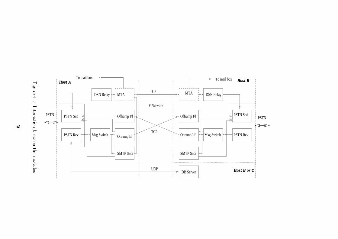
PSTN Rcv
PSTN Snd
Onramp I/f
SMTP Sndr
MTADSN Relay
Msg Switch
Offramp I/f
Onramp I/f
SMTP Sndr
Msg Switch
PSTN Snd
PSTN Rcv
IP Network
PSTNPSTN
MTA
DB Server
TCP
TCP
UDP
DSN Relay
To mail box To mail box
Offramp I/f
Host A
Host B or C
Host BFigure4.1:Interactionbetweenthemodules50

The send and receive queues are maintained as shared memory. This modulecreates the shared memory segments and the semaphores associated with these sharedmemory segments. When there is no job in the receive queue of the PSTN interface,the process waits on a semaphore. When a new job arrives, the PSTN interface wakesup this process.4.2 PSTN InterfaceThe sub modules for sending and receiving the faxes over the PSTN runs as a singleprocess. If there are jobs in the Send queue of this module, then after sending onedocument, the process waits for a certain time for the incoming facsimile call. If nocall arrives, it services the next job. If there are no jobs in the send queue, then theprocess blocks, waiting for the incoming facsimile call. If a new job now arrives onthe send queue, then the process will be signalled to service this job.The receive queue has the following data structures. This queue is shared by thethe Message Switch. The PSTN receive sub-module adds jobs and the Message switchremoves jobs from this queue. The Message Switch puts the job in the Send queue ofthe SMTP sender or the o�ramp IP Interface based on the serviceType.typedef struct{ char fileName[MAX_FILE_NAME_LEN];int noOfPages; /* filename.pageno gives the complete filename */char serviceType; /* EMAIL or FAX */char remoteFaxNo[MAX_FAX_NUM_LEN];char senderFaxNo[MAX_FAX_NUM_LEN];EmailAddrType emailAddrs[MAX_EMAIL_ADDRESSES];/* allow for multiple recipients */char ipAddr[MAX_IP_ADDR_LEN]; /* offramp IP addres */} PstnRcvQType;typedef struct{ 51

int qFront;int qRear;PstnRcvQType pstnRcvQ[MAX_RECV_Q_LEN];} PstnShmType;The send queue has the following data structures. This queue is shared by theo�ramp IP interface which puts jobs in this queue. The PSTN Send sub-module re-moves jobs from the queue after either a successful send or maximum failed attempts.The jobs are also added to the queue by the Onramp IP Interface and the SMTPSender to send the Delivery Noti�cation for failed transmissions and by the DSNRelay for relaying the DSN received from the MTA.typedef struct{ char fileName[MAX_FILE_NAME_LEN];int noOfPages; /* pages in the document */int attempts; /* number of failed attempts */long time; /* time when the last attempt was made */unsigned char type; /* whether the document is a Fax Msg or a DSN */char remoteFaxNo[MAX_FAX_NUM_LEN];char senderFaxNo[MAX_FAX_NUM_LEN];char onrampIpAddr[MAX_IP_ADDR_LEN]; /* for delivery notification */} IpPstnSendQType;typedef struct{ int signalEnabled;int qFront;int qRear;IpPstnSendQType ipPstnSendQ[MAX_SEND_Q_LEN];} IpPstnShmType;The signalEnabled variable is used by the O�ramp IP Interface so that appropriatesignals can be sent when the PSTN module has blocked, waiting for an incoming fax52

call.4.3 SMTP SenderThe recipient's email address is represented using the following structures. The validemail-id is obtained by concatenating the UserId, `@' symbol, and the domainName.typedef struct{ char userId[MAX_USER_LEN];char userName[MAX_USER_NAME_LEN];char domainName[MAX_DOMAIN_LEN];} EmailAddrType;The Send queue of the SMTP Sender has the following �elds.typedef struct{ char fileName[MAX_FILE_NAME_LEN];int noOfPages; /* pages in the document */int attempts; /* number of failed attempts */long time; /* time when the last attempt was made */int numRcpts; /* number of recipients */EmailAddrType emailAddrs[MAX_EMAIL_ADDRESSES];char senderFaxNo[MAX_FAX_NUM_LEN];} SmtpSendQType;typedef struct{ int signalEnabled;int qFront;int qRear;SmtpSendQType smtpSendQ[MAX_SEND_Q_LEN];53

} SmtpShmType;The Message Switch adds jobs and the SMTP Sender removes jobs from this queue.This module can transmit the document to multiple recipients. However, since theemail address lookup returns at most a single email address, the message will be sentto a single recipient in this implementation. The signalEnabled ag indicates whetherthe process is waiting for a new job (waiting on a semaphore) or is busy servicing jobsin a queue. This information is used by the Message Switch to wake up this processif it is waiting.4.4 Onramp and O�ramp IP InterfacesThe onramp Send queue has the following data structures. The Message Switch putsthe jobs in this queue. Jobs to this queue are also added by the PSTN Send sub-module of the PSTN Interface to send the delivery noti�cations indicating success orfailure. The jobs in the queue are removed by the Onramp IP Interface.typedef struct{ char fileName[MAX_FILE_NAME_LEN];int noOfPages; /* pages in the document */int attempts; /* number of failed attempts */long time; /* time when the last attempt was made */unsigned char type; /* Fax Msg or DSN */char remoteFaxNo[MAX_FAX_NUM_LEN];char senderFaxNo[MAX_FAX_NUM_LEN];char offrampIpAddr[MAX_IP_ADDR_LEN];} PeerSendQType;/* this structure used by onramp and pstnrcv */typedef struct{ int signalEnabled; 54

int qFront;int qRear;PeerSendQType peerSendQ[64];} PeerShmType;When the O�ramp Interface receives documents from the remote Onramp Inter-face, it directly adds it in the PSTN Send queue (Section 4.2).The data structures for the onramp-o�ramp communication is shown below.typedef struct{ char onrampFaxNum[MAX_FAX_NUM_LEN]; /* for information purpose */char onrampIpAddr[MAX_IP_ADDR_LEN]; /* used for delivery notification */}ConReqType; /* used for CONN_REQ */typedef struct{ char offrampFaxNum[MAX_FAX_NUM_LEN]; /* for information, no other use */char offrampIpAddr[MAX_IP_ADDR_LEN]; /* for verification purpose */}ConRespType; /* used for CONN_RESP */typedef struct{ char destFaxNum[MAX_FAX_NUM_LEN]; /* recipient fax number */char senderFaxNum[MAX_FAX_NUM_LEN];unsigned char dataType; /* FAX msg or DSN */}InfoDetType;typedef struct{ unsigned char relReason; /* Whether release is normal, due to error etc. */}ReleaseDetType; 55

typedef struct{ unsigned char data[MAX_DATA_LEN];}DataType;typedef struct{ long pageLen; /* Length of the data page sent */}EopType;typedef struct{ long docLen; /* Length of the total document sent */}EodType;typedef struct{ unsigned char msgType; /* Whether CON_REQ, CON_RESP ... etc. */unsigned char pad;short len; /* length of the message body used */union{ ConReqType conReq;ConRespType conResp;InfoDetType info;ReleaseDetType relDet;DataType faxData;EopType eop;EodType eod;} msgDet;} FaxgwMsgType;56
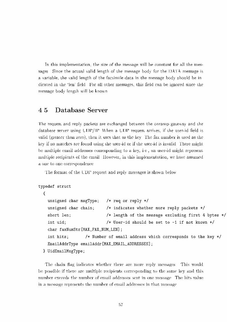
In this implementation, the size of the message will be constant for all the mes-sages. Since the actual valid length of the message body for the DATA message isa variable, the valid length of the facsimile data in the message body should be in-dicated in the `len' �eld. For all other messages, this �eld can be ignored since themessage body length will be known.4.5 Database ServerThe request and reply packets are exchanged between the onramp gateway and thedatabase server using UDP/IP. When a UDP request arrives, if the user-id �eld isvalid (greater than zero), then it uses that as the key. The fax number is used as thekey if no matches are found using the user-id or if the user-id is invalid. There mightbe multiple email addresses corresponding to a key, i.e., an user-id might representmultiple recipients of the email. However, in this implementation, we have assumeda one to one correspondence.The format of the UDP request and reply messages is shown below.typedef struct{ unsigned char msgType; /* req or reply */unsigned char chain; /* indicates whether more reply packets */short len; /* length of the message excluding first 4 bytes */int uid; /* User-id should be set to -1 if not known */char faxNumStr[MAX_FAX_NUM_LEN];int hits; /* Number of email address which corresponds to the key */EmailAddrType emailAddr[MAX_EMAIL_ADDRESSES];} UidEmailMsgType;The chain ag indicates whether there are more reply messages. This wouldbe possible if there are multiple recipients corresponding to the same key and thisnumber exceeds the number of email addresses sent in one message. The hits valuein a message represents the number of email addresses in that message.57

4.6 DSN RelayFor relaying the DSN received from the MTA, whenever a mail arrives to the faxgateway, the mailer has to be con�gured to invoke the relay and deliver the messageto it. The relay then determines whether the message is a DSN and if so, extractsthe sender fax number from the Envelope-Id �eld in the message body. The relevantparts of the message is converted from text to run-length encoding and is added inthe PSTN Send queue for transmission to the sender.
58

Chapter 5ConclusionsWe have designed a fax gateway which enables a Group 3 fax terminal connected toa telephone network to transmit fax documents to another Group 3 fax terminal alsoconnected to a telephone network utilizing the IP network for part of the communi-cation. The sending fax terminal can also transmit documents to an email accountof the recipient. The design also provides a recipient the exibility to receive thefax documents to an email account or to a Group 3 fax terminal. Delivery statusnoti�cation is provided to the sender for both successful and failed delivery.We have implemented the fax gateway using the TCP/IP protocol suite on Linux,with a few simpli�cations. We have assumed that the fax number to IP addressmapping table is available locally rather than distributed in an hierarchical manner.We have also assumed that there is a single document per fax transmission session.Application level reliability is also provided.5.1 Future WorkA considerable amount of e�ort is on for standardizing a procedure for real-time faxover IP. Implementation of the real-time fax gateways would be a challenging tasksince it involves strict conformance to T.30 timers.Our design of the fax gateway could be extended to provide the following enhance-ments. 59

� Session Internet fax service so that the sender would get a similar type of serviceprovided by the traditional fax with respect to con�rmation of fax delivery.� Integration with other Internet services.� Inter-working of di�erent types of fax terminals (ex. Group 3 and Group 4)
60

Appendix AModem AT CommandsThe AT commands listed here is the Generic Rockwell fax class 2 AT command set.Modem vendors often change, add, and delete commands based on their particularproduct and feature set. Thus these commands are not necessarily the AT commandsused within a particular modem, even if it is based on Rockwell chipset products.1. Voice Mode CommandsCommand Function#VCL=N Voice mode selection#VLN=N Relay/Speaker Control2. Service Class IDCommand Function+FCLASS= Service Class
61
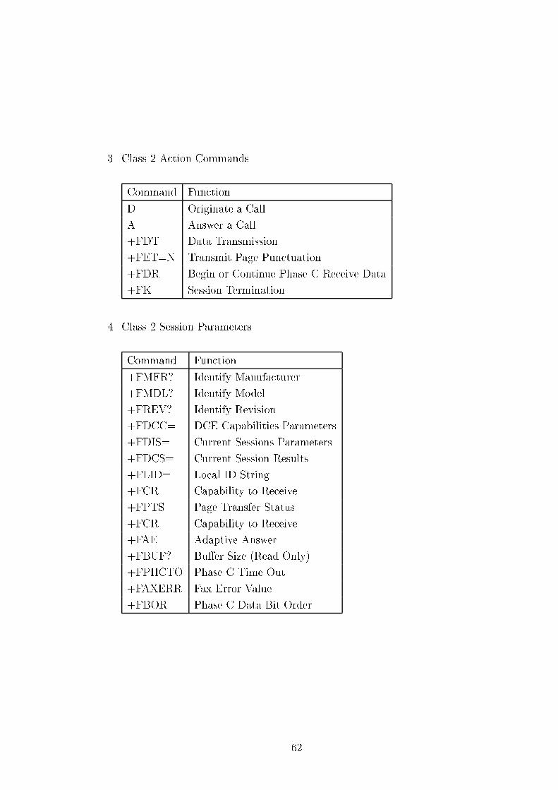
3. Class 2 Action CommandsCommand FunctionD Originate a CallA Answer a Call+FDT Data Transmission+FET=N Transmit Page Punctuation+FDR Begin or Continue Phase C Receive Data+FK Session Termination4. Class 2 Session ParametersCommand Function+FMFR? Identify Manufacturer+FMDL? Identify Model+FREV? Identify Revision+FDCC= DCE Capabilities Parameters+FDIS= Current Sessions Parameters+FDCS= Current Session Results+FLID= Local ID String+FCR Capability to Receive+FPTS= Page Transfer Status+FCR= Capability to Receive+FAE Adaptive Answer+FBUF? Bu�er Size (Read Only)+FPHCTO Phase C Time Out+FAXERR Fax Error Value+FBOR Phase C Data Bit Order
62

5. Class 2 DCE ResponsesCommand Function+FCON Facsimile Connection Response+FDCS: Report Current Session+FDIS: Report Remote Identi�cation+FCFR Indicate Con�rmation to Receive+FTSI: Report the Transmit Station ID+FCSI: Report the Called Station ID+FPTS: Page Transfer Status+FET: Post Page Message Response+FHNG Call Termination with Status
63

Bibliography[Cir95] Cirrus Logic. AT Command Set, Data Book, November 1995.http://www.cirrus.com/ftp/pubs/md1414UXXpb.pdf.[Cir96] Cirrus Logic. Modem Telephony Guide, 1996.http://www.cirrus.com/ftp/pubs/modemgd5.pdf.[FB96a] N. Freed and N. Borenstein. Multipurpose Internet Mail Extensions(MIME) Part One: Format of Internet Message Bodies. RFC 2045,November 1996.[FB96b] N. Freed and N. Borenstein. Multipurpose Internet Mail Extensions(MIME) Part Two: Media Types. RFC 2046, November 1996.[ITU96a] ITU-T (CCITT) Recommendation T.30. Procedures for Document Fac-simile Transmission in the General Switched Telephone Network, July1996.[ITU96b] ITU-T (CCITT) Recommendation T.4. Standardization of Group 3 Fac-simile Terminals for Document Transmission, July 1996.[KFR+94] J. Klensin, N. Freed, M. Rose, E. Ste�erud, and D. Crocker. SMTP ServiceExtensions. RFC 1651, July 1994.[Mas97] Larry Masinter. Terminology and Goals for Internet Fax. Internet draft,December 1997. draft-ietf-fax-goals-01.txt.[Moo96] K. Moore. SMTP Service Extension for Delivery Status Noti�cations.RFC 1891, January 1996.
64

[MZB+98] Lloyd McIntyre, Stephen Zilles, Robert Buckley, Dennis Venable, GlennParsons, and James Ra�erty. File Format for Internet Fax. Internet draft,January 1998. draft-ietf-fax-ti�plus-07.txt.[Pos82] Jonathan B. Postel. Simple Mail Transfer Protocol. RFC 821, NetworkInformation Center, ISI, University of Southern California, Marina delRey, CA, August 1982.[Roc96] Rockwell. Fax Modem Users Manual, 1996.http://www.hughes.net/rockwell.html.[Sil97] Herman R. Silbiger. Procedures for Real Time Group 3 Facsimile Commu-nication between Terminals using IP Networks. Internet draft, November1997. draft-ietf-fax-ipfax-00.txt.[Ste94] W. Richard Stevens. UNIX Network Programming. PHI, 1994.[Ste96] W. Richard Stevens. TCP/IP Illustrated, Volume 1 : The Protocols.Addison-Wesley, MA, 1996.
65


![ts wledgmen kno Ac - espace.cdu.edu.au6305/Thesis... · esp ecially hains tic an on]. An antichain is a collection of sets in h whic no o w t are comparable under set inclusion. An](https://img.dokumen.tips/doc/110x75/5b9a9f9909d3f2dc408bb791/ts-wledgmen-kno-ac-6305thesis-esp-ecially-hains-tic-an-on-an-antichain.jpg)


