Embed Size (px)
DESCRIPTION
Â
Citation preview
Revision: 1 Date: 9.22.14
KTM-007-1 (2013-Present) Page 1 of 28
Operation and Maintenance Manual
PCM-7625 R2/R3
Customer: Location: Job #: Local Rep: Rep Phone # Document #
Knight Oil Tools, Manufacturing 700 E Texas Ave. Rayne, LA 70578 Phone: (337) 334‐6969 Fax: (337) 365‐6565 www.knightmanufacturinginc.com
Revision: 1 Date: 9.22.14
KTM-007-1 (2013-Present) Page 2 of 28
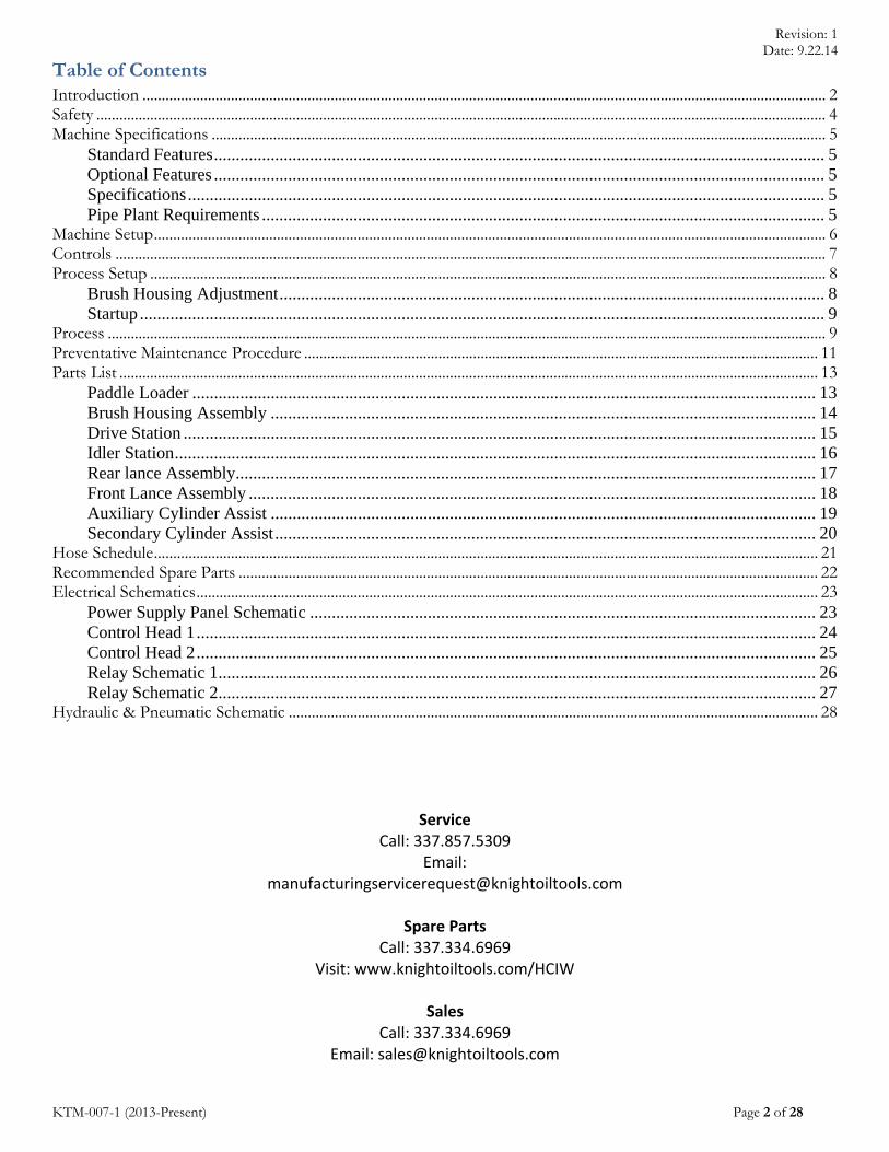
Table of Contents Introduction .................................................................................................................................................................................. 2 Safety .............................................................................................................................................................................................. 4 Machine Specifications ................................................................................................................................................................ 5
Standard Features ............................................................................................................................................ 5 Optional Features ............................................................................................................................................ 5 Specifications .................................................................................................................................................. 5 Pipe Plant Requirements ................................................................................................................................. 5
Machine Setup ............................................................................................................................................................................... 6 Controls ......................................................................................................................................................................................... 7 Process Setup ................................................................................................................................................................................ 8
Brush Housing Adjustment ............................................................................................................................. 8 Startup ............................................................................................................................................................. 9
Process ........................................................................................................................................................................................... 9 Preventative Maintenance Procedure ...................................................................................................................................... 11 Parts List ...................................................................................................................................................................................... 13
Paddle Loader ............................................................................................................................................... 13 Brush Housing Assembly ............................................................................................................................. 14 Drive Station ................................................................................................................................................. 15 Idler Station ................................................................................................................................................... 16 Rear lance Assembly ..................................................................................................................................... 17 Front Lance Assembly .................................................................................................................................. 18 Auxiliary Cylinder Assist ............................................................................................................................. 19 Secondary Cylinder Assist ............................................................................................................................ 20
Hose Schedule ............................................................................................................................................................................. 21 Recommended Spare Parts ....................................................................................................................................................... 22 Electrical Schematics .................................................................................................................................................................. 23
Power Supply Panel Schematic .................................................................................................................... 23 Control Head 1 .............................................................................................................................................. 24 Control Head 2 .............................................................................................................................................. 25 Relay Schematic 1 ......................................................................................................................................... 26 Relay Schematic 2 ......................................................................................................................................... 27
Hydraulic & Pneumatic Schematic .......................................................................................................................................... 28
Service Call: 337.857.5309
Email: [email protected]
Spare Parts
Call: 337.334.6969 Visit: www.knightoiltools.com/HCIW
Sales
Call: 337.334.6969 Email: [email protected]

Revision: 1 Date: 9.22.14
KTM-007-1 (2013-Present) Page 3 of 28
Introduction
PCM7625 Pipe Cleaning Machine For environments that noise and dust control are required or desired, Knight Manufacturing’s PCM is an excellent choice. The standard dual brush housing cleans most pipe in one pass, increasing productivity, which results in a more productive and safer work environment.
Revision: 1 Date: 9.22.14
KTM-007-1 (2013-Present) Page 4 of 28
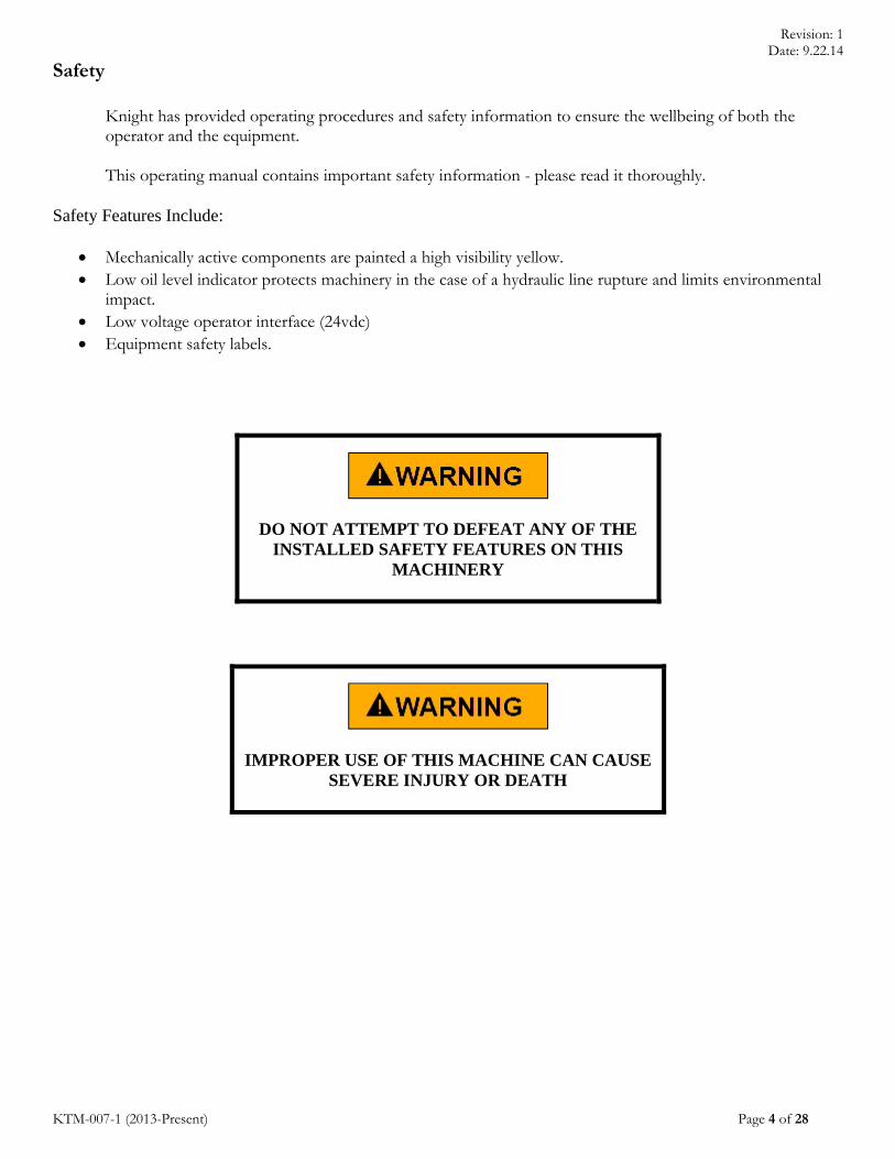
Safety
Knight has provided operating procedures and safety information to ensure the wellbeing of both the operator and the equipment.
This operating manual contains important safety information - please read it thoroughly.
Safety Features Include:
Mechanically active components are painted a high visibility yellow. Low oil level indicator protects machinery in the case of a hydraulic line rupture and limits environmental
impact. Low voltage operator interface (24vdc) Equipment safety labels.
DO NOT ATTEMPT TO DEFEAT ANY OF THE INSTALLED SAFETY FEATURES ON THIS
MACHINERY
IMPROPER USE OF THIS MACHINE CAN CAUSE
SEVERE INJURY OR DEATH

Revision: 1 Date: 9.22.14
KTM-007-1 (2013-Present) Page 5 of 28
Machine Specifications
Standard Features
Dual wire brush for outside diameter cleaning Lance for inside diameter cleaning Dual hydraulic power supply
o One hydraulic pump for conveyor motors & auxiliary equipment o One for wire brushes
Range 2 pipe Left or right hand pipe loading configuration
Optional Features
Outside diameter descaler Grip enhancer Range 3
o Accommodates pipe lengths up to 46’ o 24’ added to overall length of machine
Specifications
Pipe capacity o Tubing min. OD 2- 3/8” o Drill pipe max. OD 6- 5/8”
Overall length 84’ (108’ for R3) Width 30” Height 7’ Drive station spacing 6’ (4’ option available) Weight 7,000 lbs. (Max Gross Weight)
Pipe Plant Requirements
Electrical 230/480V, 3 Phase, 60 Hz (Others available upon request) Compressed air 100 PSI Plant Air System Required @ 150 CFM Rack height 36”- 44”

Revision: 1 Date: 9.22.14
KTM-007-1 (2013-Present) Page 6 of 28
Machine Setup For proper operation, the machine must be installed straight, coplanar and horizontally level.
1. Remove the lance if it is installed on the machine. 2. Position frame components and loosely bolt them
together. 3. Level the machine in the Z direction. To do this,
establish a base line from a stationary object (such as installed pipe racks) and adjust the frame elevation of the load / unload side of the machine. The other frame components elevation is adjusted via the jack screws mounted to the feet. The elevation tolerance from the reference is + 1/8”.
4. Align the frame components in the X direction. Alignment tolerance is Y + 1/8” as measured from the machines axial center line through the length of the entire machine at the component joints and perpendicular to the pipe racks.
5. Anchor bolt the feet to the foundation. The minimum foundation thickness is 4” concrete. The anchor bolts may be left loose and tightened after full testing.
6. Verify that the machine is straight (along the X axis), within the elevation tolerance (the Z axis) and reasonably flat to the X-Y plane.
7. Tighten the frame connector bolts without disturbing the alignment. Torque the bolts to 120 ft.-lb.. 8. Tighten the machine feet to the torque value recommended by the anchor bolt manufacturer. 9. Proceed with electrical and hydraulic installation. (See pages 28-31 for electrical and hydraulic schematics.) 10. Install duct collection system according to the manufacturer’s procedures manual.
|----------------------Load/Unload---------------|----Table----|-----------------------Lance Side---------------------|

Revision: 1 Date: 9.22.14
KTM-007-1 (2013-Present) Page 7 of 28
Controls Standard PCM 7625 Layout
(Standard Control Layout – Specific Control Locations May Change)
Function 1 Emergency Stop 2 Machine (on/off) Switch 3 Brush Motor Off/On 4 Dust Collector Off/On 5 Rear Brush Adjustment up/down 6 Pipe Speed Control 7 Pipe Load/Unload – Conveyor Direction 8 OD Scrapper Engage (if equipped) 9 Brush #1 Engage 10 Brush #2 Engage 11 Rattler Motor On

Revision: 1 Date: 9.22.14
KTM-007-1 (2013-Present) Page 8 of 28
Process Setup
Brush Housing Adjustment
1. When loading the first pipe, or changing pipe sizes, the brush housing will need to be adjusted accordingly. 2. Move the joint under the brush housing frame, engage the brush and adjust the rear adjustment cylinder (1)
with the control switch (control #6) and rear pin (2) so that the brush housing frame is level when contacting the pipe.
a. Ensure that the front and rear brush housing adjustments are positioned to effectively process the pipe. Failure to do so could result in damage to the machinery or a decrease in efficiency.
2
1

Revision: 1 Date: 9.22.14
KTM-007-1 (2013-Present) Page 9 of 28
Startup
1. Before starting, ensure that all daily maintenance is completed. 2. Install appropriate rattler motor and cleaning head. 3. Turn the Machine Control ON (via control #3). 4. Turn the Dust Collector Control ON (via control #4). 5. Ensure that the Rattler Motor Control (control #10) is in the OFF position. 6. Ensure that the Brush Housing Controls (control #9) are in the disengaged position. 7. Load the first joint of pipe onto the machine (control #7). 8. Locate collar stop pins so that only one joint is picked up with the paddles. 9. Adjust brush frame so that it is level when brush is engaging pipe. 10. Turn the Brush Motors Button ON (via control #8).
Note: Reference page 7 for control panel layout.
Process
1. With the pipe on the rack, actuate the Pipe Index Load (control #7). This will load the pipe onto the machine.
PRIOR TO LOADING OR OFFLOADING PIPE, ENSURE THAT THERE ARE NO PERSONNEL
OR EQUIPMENT IN THE PIPES PATH
2. Turn Brush Motor on (control #3). 3. Using the Motor Directional Control (control #7), CONVEY the pipe toward the Table Section. 4. Adjust the drive motor speed as required with the Pipe Speed Control (control #6). 5. If equipped, LOWER the OD Scraper, after the pipe is under the Scraper Head. 6. After the pipe is under the Brush Housing Assembly, the Brush Housing can be placed in the engaged
position (via control #9 & 10). 7. Turn the Rattler Motor ON (via control #11) after the rattler motor is inside the pipe. 8. If the pipe has traveled beyond the Brush Housing Assembly, ensure that the Brush Housing is in the UP
position (via control #9 & 10), prior to conveying the pipe back toward it. 9. If the pipe has traveled beyond the OD Scraper, ensure that the OD Scraper head is in the UP position,
prior to conveying the pipe back toward it. 10. Using the Motor Directional Control, (Control #7), CONVEY the pipe toward the Load Section.
STAY AWAY FROM ALL YELLOW MECHANICAL PARTS WHILE THE MACHINE IS ON. THEY CAN
MOVE WITHOUT WARNING CAUSING SEVERE INJURY
11. If required, LOWER the OD Scraper, after the pipe is under the Scraper Head.

Revision: 1 Date: 9.22.14
KTM-007-1 (2013-Present) Page 10 of 28
12. After the pipe is under the Brush Housing Assembly, the Brush Housing can be placed in the engaged position (via control #9).
13. Turn the Rattler Motor OFF (via control #11), prior to the ID Scraper exiting the pipe. (Failure to do so can result in both personal injury and damage to equipment)
14. After the pipe has been processed, convey the pipe back to the load side of the machine. 15. Be sure to properly collar the pipe prior to offloading. 16. After the pipe has been properly collared, ACTUATE the Pipe Index Load (control #7). This will offload
the processed pipe and load the next pipe onto the machine. 17. Repeat as required
PRIOR TO LOADING OR OFFLOADING PIPE, INSURE THAT THERE ARE NO
PERSONNEL OR EQUIPMENT IN THE PIPES PATH
Revision: 1 Date: 9.22.14
KTM-007-1 (2013-Present) Page 11 of 28
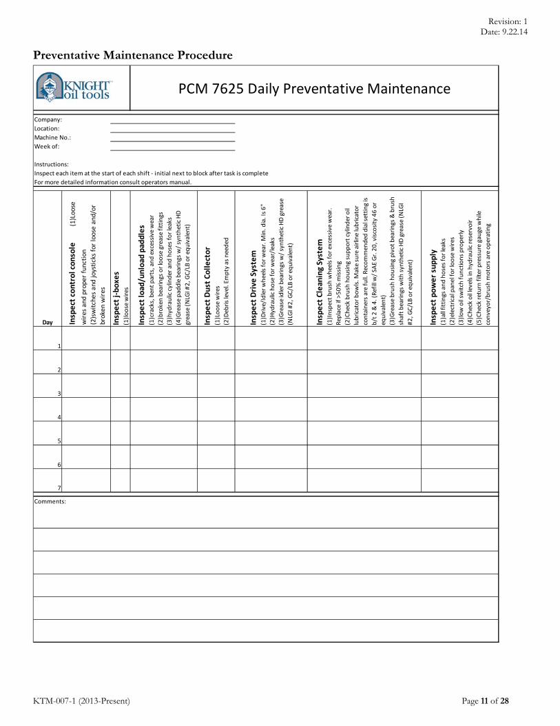
Preventative Maintenance Procedure
Company:
Location:
Machine No.:
Week of:
Instructions:
Inspect each item at the start of each shift ‐ initial next to block after task is complete
For more detailed information consult operators manual.
Day Inspect control console (1)Loose
wires and
proper function
(2)switches and
joysticks for loose and/or
broken
wires
Inspect j‐boxes
(1)loose wires
Inspect load/unload
paddles
(1)cracks, bent parts, and excessive wear
(2)broken bearings or loose grease fittings
(3)hydraulic cylinder and hoses for leaks
(4)Grease paddle bearings w/ synthetic HD
grease (NLGI #2, G
C/LB or equivalent)
Inspect Dust Collector
(1)Loose wires
(2)Debris level. Em
pty as needed
Inspect Drive
System
(1)Drive/Idler wheels for wear. M
in. dia. Is 6"
(2)Hydraulic hose for wear/leaks
(3)Grease idler bearings w/ synthetic HD grease
(NLGI #2, G
C/LB or equivalent)
Inspect Cleaning System
(1)Inspect brush wheels for excessive wear.
Replace if >50% missing
(2)Check brush housing support cylinder oil
lubricator bowls. M
ake sure airline lubricator
containers are full. Recommended
dial setting is
b/t 2 & 4. (Refill w/ SA
E Gr. 20, viscosity 46 or
equivalent)
(3)Grease brush housing pivot bearings & brush
shaft bearings with synthetic HD grease (NLGI
#2, G
C/LB or equivalent)
Inspect power supply
(1)all fittings and hoses for leaks
(2)electrical panel for loose wires
(3)low oil sw
itch functions properly
(4)Check oil levels in hydraulic reservoir
(5)Check return filter pressure gauge while
conveyor/brush motors are operating
1
2
3
4
5
6
7
Comments:
PCM 7625 Daily Preventative Maintenance

Revision: 1 Date: 9.22.14
KTM-007-1 (2013-Present) Page 12 of 28
Company:
Location:
Machine No.:
Week of:
Instructions:
Inspect each item at the start of each shift ‐ initial next to block after task is complete
For more detailed information consult operators manual.
Year Power Supply
(1)Drain hydraulic reservoir & clean
w/
suitable solvent.
(2)Rem
ove suction strainer & clean
w/
solvent
(3)Change hydraulic filters
Machine Alignment
(1) Verify machine is aligned
properly.
Correct if necessary
Comments:
PCM 7625 Yearly Preventative Maintenance

Revision: 1 Date: 9.22.14
KTM-007-1 (2013-Present) Page 13 of 28
Parts List
Paddle Loader
Revision: B
Item # Part # Description Quantity 1 13606 PADDLE FAB ASSEM 1 2 13592 PADDLE WEAR PAD 1 3 14645 SPHERICAL BEARING 2 4 13609 BEARING BLOCK 2 5 16086 GREASE ZERK, 1/8 NPT 2 6 17053 EXTERNAL RETAINING RING, 1 1/4" 2 7 17649 WASHER, FLAT, .50" 4 8 17651 WASHER, FLAT, .625" 1 9 14140 WASHER, LOCK, .50" 4 10 14361 BOLT, HHCS, .50" X 3.50" NC GR5 4 11 14495 BOLT, FHSCS, .50" X 2" 2 12 16524 NUT, JAM LOCK, .50" 2 13 16532 NUT, LOCK, .625" NC NYLOCK 1 14 14124 NUT, HEX, .5" NC 4 15 38707 BOLT, SHOULDER, .75 X 4.25 X .625-11 1
Revision: 1 Date: 9.22.14
KTM-007-1 (2013-Present) Page 14 of 28
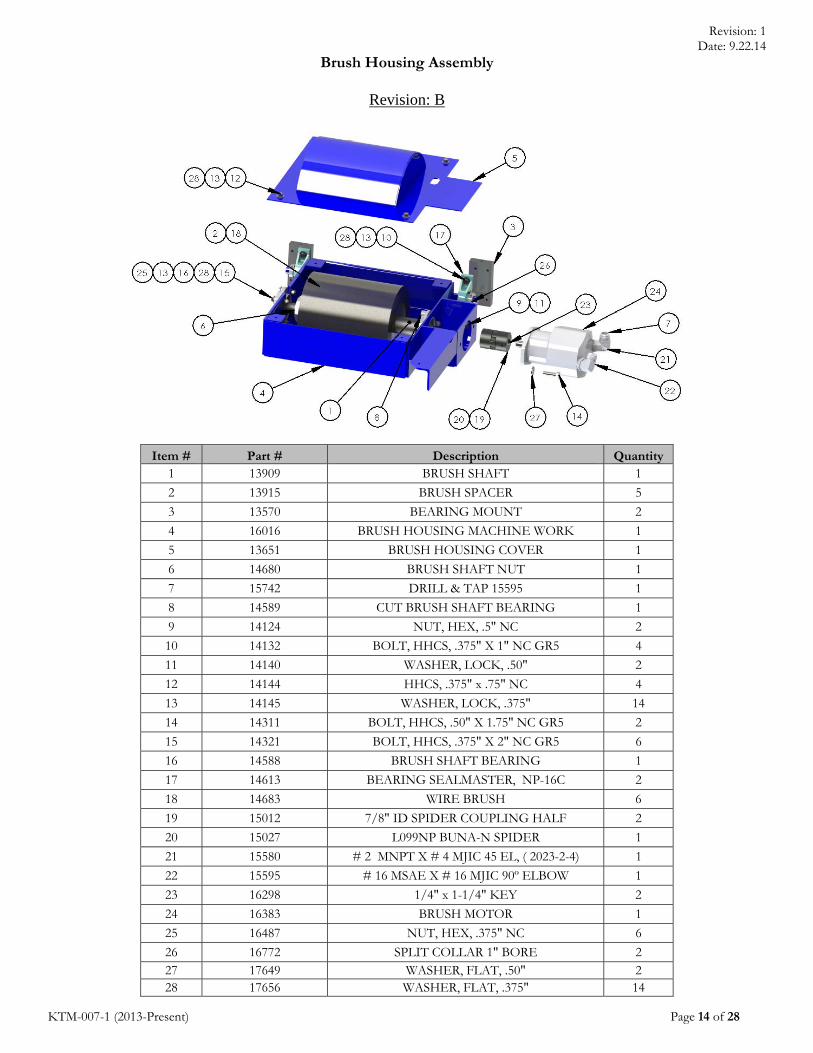
Brush Housing Assembly
Revision: B
Item # Part # Description Quantity 1 13909 BRUSH SHAFT 1
2 13915 BRUSH SPACER 5
3 13570 BEARING MOUNT 2
4 16016 BRUSH HOUSING MACHINE WORK 1
5 13651 BRUSH HOUSING COVER 1
6 14680 BRUSH SHAFT NUT 1
7 15742 DRILL & TAP 15595 1
8 14589 CUT BRUSH SHAFT BEARING 1
9 14124 NUT, HEX, .5" NC 2
10 14132 BOLT, HHCS, .375" X 1" NC GR5 4
11 14140 WASHER, LOCK, .50" 2
12 14144 HHCS, .375" x .75" NC 4
13 14145 WASHER, LOCK, .375" 14
14 14311 BOLT, HHCS, .50" X 1.75" NC GR5 2
15 14321 BOLT, HHCS, .375" X 2" NC GR5 6
16 14588 BRUSH SHAFT BEARING 1
17 14613 BEARING SEALMASTER, NP-16C 2
18 14683 WIRE BRUSH 6
19 15012 7/8" ID SPIDER COUPLING HALF 2
20 15027 L099NP BUNA-N SPIDER 1
21 15580 # 2 MNPT X # 4 MJIC 45 EL, ( 2023-2-4) 1
22 15595 # 16 MSAE X # 16 MJIC 90º ELBOW 1
23 16298 1/4" x 1-1/4" KEY 2
24 16383 BRUSH MOTOR 1
25 16487 NUT, HEX, .375" NC 6
26 16772 SPLIT COLLAR 1" BORE 2 27 17649 WASHER, FLAT, .50" 2 28 17656 WASHER, FLAT, .375" 14

Revision: 1 Date: 9.22.14
KTM-007-1 (2013-Present) Page 15 of 28
Drive Station
Revision: C
Item # Part Description Quantity 1 13566 DRIVE HUB (020-00024) 1 2 14131 BOLT, HHCS, .75" X 1.25" 1 3 14133 WASHER, LOCK, .75" 1 4 14134 LOCK WASHER CASTING 1 5 15612 # 4 MSAE X # 4 MJIC 90º ELBOW, ( 2062-4-4) 1 6 15739 # 10 MSAE X #10 MJIC 90º ELBOW, (2062-10-10) 1 7 15790 # 10 MSAE X # 10 MJIC LONG 90º ELBOW 1 8 16298 1/4" x 1-1/4" KEY 1 9 16391 CHARLYNN HYD MOTOR P/N - 101-2435009 (HT) 1 10 17149 SET SCREW, .3125"-18 X .3125" 2 11 22510 WHEEL, 18001JT, GROOVED 1

Revision: 1 Date: 9.22.14
KTM-007-1 (2013-Present) Page 16 of 28
Idler Station
Revision: C
Item # Part Description Quantity1 28991 NEEDLE BEARING RACER, W. FLANGE 12 14435 1" X 2.5" SHOULDER BOLT 13 13979 WASHER, FLAT, 1" X 2" X .125" BRASS 24 14133 WASHER, LOCK, .75" 15 14641 Needle Bearing (J32-1264) 16 16082 GREASE FITG, .25"-28 X .75" 17 16485 NUT, HEX, .75" NC 18 17652 WASHER, FLAT, 1" 19 17653 WASHER, FLAT, .75" 1

Revision: 1 Date: 9.22.14
KTM-007-1 (2013-Present) Page 17 of 28
Rear lance Assembly
Revision: B
Item # Part # Description Quantity1 13596 ADJUSTMENT SCREW 12 43669 KNOB, .375" STAR TRUTROL (MODIFIED) 13 13602 ELEVATION ADJUSTMENT COVER 14 13604 PERFORATED TUBE ASSEMBLY (REAR) 15 14124 NUT, HEX, .5" NC 26 14140 WASHER, LOCK, .50" 27 14359 BOLT, HHCS, .50" X 2.50" NC GR5 28 15288 ROLL PIN, 1/8 " X 3/4" 19 15653 # 16 FNPT X #16 MJIC 90º ELBOW, (2025-16-16) 110 17218 LEVELING SHIM (BEVEL WASHER) 9115A033 2

Revision: 1 Date: 9.22.14
KTM-007-1 (2013-Present) Page 18 of 28
Front Lance Assembly
Item # Part # Description Quantity1 13596 ADJUSTMENT SCREW 12 43669 KNOB, .375" STAR TRUTROL (MODIFIED) 13 13603 ELEVATION ADJUSTMENT COVER 14 21207 PERFORATED TUBE ASSEMBLY 15 15288 ROLL PIN, 1/8 " X 3/4" 16 22246 WASHER, FLAT, .375" FW-3 2

Revision: 1 Date: 9.22.14
KTM-007-1 (2013-Present) Page 19 of 28
Auxiliary Cylinder Assist
Revision: B
Item # Part # Description Quantity
1 20563 GUIDE, ADAPTER GUIDE 12 13959 AUXILLIARY CYLINDER ROD & ROD END 13 14037 FITG, HYD 14 15450 FITG, HYD 15 15580 FITG, HYD 16 15607 FITG, HYD 1

Revision: 1 Date: 9.22.14
KTM-007-1 (2013-Present) Page 20 of 28
Secondary Cylinder Assist
Revision: D
ITEM # PART NUMBER DESCRIPTION QTY.
1 13567 ROD EXTENSION 1 2 13568 BOOT ANCHOR 1 3 13569 ROD SPACER 1 4 14166 ROD GUIDE 1 5 107-701-008-00 AUXILLIARY CYLINDER ASSIST 1 6 14135 NUT, JAM, 1" NF 1 7 14138 WASHER, LOCK, .25" 1 8 14140 WASHER, LOCK, .50" 1 9 14492 BOLT, SHCS, .25'' X 2'' GR5 1 10 14504 BOLT, SHCS, .25" X 1.75" NC GR5 1 11 14513 HONDA # 51611-459-880 RUBBER BOOT 1 12 14629 BEARING ROD END 1 13 15098 MODIFIED AIR CYL 1 14 15582 3/8" MP X 1/4" MJIC 90 DEG (2024-6-4) 2 15 16098 HAIR PIN COTTER .243 X 5-1/4 LG 1 16 16483 NUT, HEX, .25" NC 3 17 16511 NUT, HEX, .5" NF 2 18 17649 WASHER, FLAT, .50" 2 19 17681 WASHER, SPRING, 0.375 4 20 23129 BOLT, SHOULDER, .5"x.75"x.375"-16 2

Revision: 1 Date: 9.22.14
KTM-007-1 (2013-Present) Page 21 of 28
Hose Schedule Hose # From To Additional
Notes Description Qty
107-610-129-00 Front table paddle tubing Front load side tubing Short jumper hose from table to load
side frames
15547, HOSE 16234 7" LG, 15562, 15796 2
107-610-131-00 Top motor tubing Hydraulic motor 15562, HOSE 16234
35" LG, 15562 8
107-610-133-00 Rear table motor tubing Rear load/lance frame tubing Short jumper hose
from table to load/lance frames
15547, HOSE 16234 13" LG, 15562,
15796 4
107-610-137-00 Brush motor Tank Please specify length
when ordering
15560, HOSE 16233 LENGTH TBD,
15560 2
107-610-138-00 Brush motor pump Brush motor Please specify length when ordering
15560, HOSE 16233 LENGTH TBD,
15555 2
107-610-141-00 Case drain tubing Tank Please specify length when ordering
15562, HOSE 16234 LENGTH TBD,
15562 1
107-610-142-00 Manifold station 3 Brush lift cylinder piping Hoses are identical
for P & T
15562, HOSE 16234 LENGTH TBD,
15568 2
107-610-144-00 Manifold station 1 Paddle tubing Please specify length
when ordering
15562, HOSE 16234 LENGTH TBD,
15562 2
107-610-146-00 Manifold station 2 Motor circuit Please specify length
when ordering
15562, HOSE 16234 LENGTH TBD,
15562 2
107-610-101-00 Brush motor piping Brush motor 15560, HOSE 16233
45" LG, 15555 4
107-610-105-00 Brush motor Auxiliary assist cylinder 15538, HOSE 16228
30" LG, 15538 2
107-610-107-00 Front table air tubing Regulator/Lubricator/Filter
Assembly Air hose 15610, HOSE 13973
17" LG, 15610 2
107-610-110-00 Regulator/Lubricator/Filter
Assembly Bottom table air tubing Air hose
15610, HOSE 13973 17" LG, 15610
2
107-610-115-00 Bottom table air tubing Air valve assembly Air hose 15610, HOSE 13973
8" LG, 15610 2
107-610-116-00 Air valve assembly Brush air cylinder, A Port Air hose 15610, HOSE 13973
75" LG, 15610 2
107-610-117-00 Air valve assembly Brush air cylinder, B Port Air hose 15610, HOSE 13973
43" LG, 15610 2
107-610-119-00 Hydraulic Motor Case drain tubing 15538, HOSE 16228
29" LG, 15538 8
107-610-121-00 Bottom motor tubing Hydraulic Motor 15562, HOSE 16234
21" LG, 15562 8
107-610-184-00 Brush lift cylinder piping Brush lift cylinder 15562, HOSE 16234
15" LG, 15562 2
107-610-187-00 IB lance air piping OB lance air piping 15560, HOSE 16233
31" LG, 15560 1
107-610-193-00 OB lance air piping Rear lance support 15560, HOSE 16233
39" LG, 15549 1

Revision: 1 Date: 9.22.14
KTM-007-1 (2013-Present) Page 22 of 28
Recommended Spare Parts
Level A Items (Frequent) Part # Description Qty Price 13959 OD Brush 8 $32.83 17719 Drive Wheels 10 $12.45 13592 Paddle Wear Pad 4 $20.73 17718 Idler Wheel 6 $12.72 16734 Power Supply, (480V/24VDC)Power Supply 1 $279.54 14974 Contactor, 24vdc coil ;25HP,42A 1 $63.5 17014 Thermal Overload relay (18-26A) 1 $39.25 14203 Amplifier, WhiteOak 600mA 24vdc 1 $251.34
Level B Items (Moderate) 14037 Lenz Fitg 2 $3.70 14683 Chrome Rod 2 $67.28 14435 Idler Shoulder Bolt 6 $34.24 14641 Needle Bearing 3 $1.93 13979 1” Brass Washer 6 $1.48
16391 (16392) High Torque Hydraulic Motor (High Speed Motor) 1 $193.43 16444 Contactor, 24vdc coil ; 5hp,32A 1 $40.00 13989 Select Switch, Two Position Switch 800T-H2A 1 $68.96 17391 Joystick, 4 Way Joystick 800T- T4T2AAXX 1 $296.39 17314 Joystick, 1 Way Joystick Maint 800T-T1A1 1 $171.04 24950 Potentiometer, 5K Potentiometer 800T-U24 1 $196.08 38616 Timer Relay ,H3DS-AL-24/230ac-24/48dc 1 $33.93 16030 Fuse, 1-1/2A MDL-11/2(Bussman) 5 $1.35
Level C Items (Intermittent) 42131 Hydraulic Pump (Brush) 1 $1,150.0022353 Hydraulic Pump (Auxiliary Systems) 1 $1,031.15

Revision: 1 Date: 9.22.14
KTM-007-1 (2013-Present) Page 23 of 28
Electrical Schematics
Power Supply Panel Schematic

Revision: 1 Date: 9.22.14
KTM-007-1 (2013-Present) Page 24 of 28
Control Head 1

Revision: 1 Date: 9.22.14
KTM-007-1 (2013-Present) Page 25 of 28
Control Head 2

Revision: 1 Date: 9.22.14
KTM-007-1 (2013-Present) Page 26 of 28
Relay Schematic 1

Revision: 1 Date: 9.22.14
KTM-007-1 (2013-Present) Page 27 of 28
Relay Schematic 2

Revision: 1 Date: 9.22.14
KTM-007-1 (2013-Present) Page 28 of 28
Hydraulic & Pneumatic Schematic