Embed Size (px)
Citation preview

i
Fall 2002
Dear Student,
This chapter is from the first edition of Randy Knight’s Physics for Scientists andEngineers: A Strategic Approach, scheduled for publication in 2004. We’veprinted this preview booklet to gather feedback from both students and instruc-tors. While these pages are not yet final, they already reflect the input of thou-sands of students and hundreds of instructors who were involved in reviewingand class testing over the last few years.
Randy Knight’s goal in writing this book is to give students what they need inorder to succeed in their physics course: effective coverage of the concepts ofphysics as well as the skills needed to become successful problem-solvers. Wenow need you to tell us: does this book meet its goals?
We would greatly appreciate your comments on the writing, illustrations, and fea-tures that you will find throughout this chapter. After completing the chapter,please take a moment to fill out the attached Student Questionnaire, and giveit to your instructor. You may either read this material in addition to yourassigned textbook, or in place of your assigned textbook for the correspondingtopics.
Thank you for participating in this student review. Your feedback will influencehow we develop our texts.
We look forward to hearing from you.
Sincerely,
Adam Black, PhD Susan Winslow Alice Houston, PhDExecutive Editor Market Development Manager Development Editor
To instructors:
Additional information about this textbook can be found at:www.aw.com/bc/info/knight
Student review resources (including sections from the instructor’s guide FiveEasy Lessons: Successful Strategies for Physics Teaching and full solutions to theworkbook and end-of-chapter problems) are also available at the above url.Please contact your sales rep or Susan Winslow ([email protected]) foraccess details.
WB_Knight.FM.33.pgs 8/1/02 12:55 PM Page i

Randy Knight has taught introductory physics for over 20 years at Ohio StateUniversity and California Polytechnic State University, where he is currently Pro-fessor of Physics. Professor Knight received a bachelor’s degree in physics fromWashington University in St. Louis and a Ph.D. in physics from the University ofCalifornia, Berkeley. He was a postdoctoral fellow at the Harvard-SmithsonianCenter for Astrophysics before joining the faculty at Ohio State University. It wasat Ohio State, under the mentorship of Professor Leonard Jossem, that he beganto learn about the research in physics education that, many years later, led to thisbook.
Professor Knight’s research interests are in the field of lasers and spec-troscopy. He recently led the effort to establish an environmental studies programat Cal Poly, where, in addition to teaching introductory physics, he also teachesclasses on energy, oceanography, and environmental issues. When he’s not in theclassroom or in front of a computer, you can find Randy hiking, sea kayaking,playing the piano, or spending time with his wife Sally and their seven cats.
iiii
About the Author
Randall D. Knight
WB_Knight.FM.33.pgs 8/1/02 12:55 PM Page ii
Knight’s Physics for Scientists and Engineers: A Strategic ApproachStudent Questionnaire
Dear Student: After completing Chapter 33 please take a few minutes to answer these questions. When you are done,please remove this page from the booklet and return it to your professor. We look forward to hearing what you think, andwe very much appreciate your feedback to help us produce a book that is most effective for you.
1. Name (print): _____________________________________ School: _______________________________________
Your Major: ______________________________________ Type of School: 2-year 4-year
Instructor Name: ___________________________________ State: _________________________________________
2. Authors of the textbook currently used in your course:
1. Serway/Beichner 2. Halliday/Resnick/Walker 3. Young/Freedman 4. Tipler5. Giancoli 6. Wolfson/Pasachoff 7. Other ________________________________
3. What was the most difficult topic you had to learn in this chapter? ___________________________________________
Did our book, and workbook sections, help you to understand this topic? Yes No
If so, how: _______________________________________________________________________________________
________________________________________________________________________________________________
________________________________________________________________________________________________
4. Several features are included throughout the book to ensure the concepts are understandable, and to help you learn thematerial. Please rate the following features (please circle one number per line):
Very Helpful Somewhat Helpful Not Helpful
Chapter introduction and opening photo 3 2 1
“Looking Ahead” goals 3 2 1
Writing style 3 2 1
Figures 3 2 1
“Note �” paragraphs 3 2 1
“Stop To Think” questions 3 2 1
Chapter Summary Schematic 3 2 1
“Key Concepts and Terms” list 3 2 1
5. Several features are included throughout the book to help you improve your problem-solving skills. Please rate the fol-lowing features (please circle one number per line):
Very Helpful Somewhat Helpful Not Helpful
Model/Visualize/Solve/Assess Strategy 3 2 1
Problem-solving “Tactics Boxes” 3 2 1
Worked example problems 3 2 1
Workbook exercises 3 2 1
End-of-chapter problems 3 2 1
Answers to odd-numbered problems 3 2 1
WB_Knight.FM.33.pgs 8/1/02 12:55 PM Page iii

6. Using your current text as a basis for comparison, please rate this material from Knight in the following areas (pleasecircle one number per line):
Knight compared to my current text: Better The Same Not as Good
Accessible and interesting reading 3 2 1
Helps me to understand the concepts 3 2 1
Helps me to build problem-solving skills 3 2 1
End-of-chapter summaries 3 2 1
Figures 3 2 1
7. Some of the figures in this book include more explanations and comments as labels on the figures (rather than in thecaptions or in the accompanying text). Did you find them clear and helpful? What didn’t you like?
8. What did you like most about this chapter? _____________________________________________________________
9. What did you like least about this chapter? How can we improve it? _________________________________________
_________________________________________________________________________________________________
_________________________________________________________________________________________________
_________________________________________________________________________________________________
10. Would you recommend Knight to your professor for this course? Yes No
Why or why not? _________________________________________________________________________________
11. May Addison Wesley quote you in the promotion of Knight’s Physics for Scientists and Engineers: A StrategicApproach?
Yes No Signature: ____________________________________________________
Dear Professor: Thank you for participating in this student review. When your students are finished, please return theircompleted questionnaires to your local sales representative, or mail them to:
Susan WinslowMarket Development ManagerAddison Wesley Publishers1301 Sansome StreetSan Francisco, CA 94111
WB_Knight.FM.33.pgs 8/1/02 12:55 PM Page iv

v
Part I Newton’s LawsChapter 1 Concepts of MotionChapter 2 Kinematics:The Mathematics
of MotionChapter 3 Vectors and Coordinate
SystemsChapter 4 Force and MotionChapter 5 Dynamics I: Motion
Along a LineChapter 6 Dynamics II: Motion in a PlaneChapter 7 Dynamics III: Motion in a CircleChapter 8 Newton’s Third Law
Part II Conservation LawsChapter 9 Impulse and MomentumChapter 10 EnergyChapter 11 Work
Part III Applications of NewtonianMechanics
Chapter 12 Newton’s Theory of GravityChapter 13 Rotational DynamicsChapter 14 OscillationsChapter 15 Fluids and Elasticity
Part IV ThermodynamicsChapter 16 Solids, Liquids, and GasesChapter 17 Work, Heat, and the First Law
of ThermodynamicsChapter 18 The Micro/Macro ConnectionChapter 19 Thermodynamics
ContentsPhysics for Scientists and Engineers: A Strategic Approach Randall D. Knight
Part V Waves and OpticsChapter 20 Traveling WavesChapter 21 SuperpositionChapter 22 Wave OpticsChapter 23 Ray OpticsChapter 24 A Closer Look at Light
and Matter
Part VI Electricity and MagnetismChapter 25 ElectricityChapter 26 The Electric FieldChapter 27 Gauss’s LawChapter 28 Current and ConductivityChapter 29 The Electric PotentialChapter 30 Potential and FieldChapter 31 Fundamentals of CircuitsChapter 32 The Magnetic FieldChapter 33 Electromagnetic InductionChapter 34 Maxwell’s Equations and
Electromagnetic WavesChapter 35 AC Circuits
Part VII Relativity and Quantum PhysicsChapter 36 RelativityChapter 37 The End of Classical PhysicsChapter 38 Waves, Particles, and QuantaChapter 39 The Quantum AtomChapter 40 Wave functions and
ProbabilitiesChapter 41 One-Dimensional Quantum
MechanicsChapter 42 Atomic PhysicsChapter 43 Nuclear Physics
WB_Knight.FM.33.pgs 8/1/02 12:55 PM Page v

WB_Knight.FM.33.pgs 8/1/02 12:55 PM Page vi

What do electric generators, metal detectors, video recorders, computerhard disks, and cell phones have in common? Surprisingly, these diverse tech-nologies all stem from a single scientific principle, electromagnetic induction.Electromagnetic induction is the process of generating an electric current byvarying the magnetic field that passes through a circuit.
The many applications of electromagnetic induction make it an importanttopic for study. But more fundamentally, electromagnetic induction establishes animportant link between electricity and magnetism. We’ve been studying electricand magnetic fields as if they were separate, independent fields. Electromagneticinduction forms a link between and a link with important implications forunderstanding light as an electromagnetic wave.
Electromagnetic induction is a subtle topic, so we will build up to it gradually.We’ll first examine different aspects of induction and become familiar with itsbasic characteristics. Section 33.5 will then introduce Faraday’s law, a new law ofphysics not derivable from any previous laws you have studied. The remainder ofthe chapter will explore its implications and applications.
33.1 Induced CurrentsOersted’s 1820 discovery that a current creates a magnetic field generated enor-mous excitement. Dozens of scientists immediately began to explore the implica-tions of this discovery. One question they hoped to answer was whether theconverse of Oersted’s discovery was true. That is, can a magnet be used to createa current? There was not yet a good understanding of the origins or properties of electricity and magnetism, so scientists hoping to generate a current from
Br
,Er
1
Looking AheadThe goal of Chapter 33 is to under-stand and apply electromagneticinduction. In this chapter you willlearn:
� What induced currents are, howthey are generated, and someof their applications.
� To calculate magnetic flux.� To use Lenz’s law and Faraday’s
law to determine the directionand size of induced currents.
� How induced electric and mag-netic fields lead to electromag-netic waves.
� What inductors are and howthey are used.
Looking BackThis chapter will join togetherideas about magnetic fields andelectric potential. Please review:
� Section 11.3 The Vector DotProduct
� Section 28.4 Sources of ElectricPotential
� Sections 30.6–30.8 MagneticFields and Magnetic Forces
ElectromagneticInduction33
Electromagnetic induction is thescientific principle that underliesmany modern technologies, fromthe generation of electricity tocommunications and data storage.
38685.33.beta.v9.ww 8/1/02 11:31 AM Page 1

magnetism had little to guide them. Many experiments were reported in whichwires and coils were placed in or around magnets of various sizes and shapes, butno one was able to generate a current.
On the other side of the Atlantic, the American scientist Joseph Henry read ofthese new discoveries with great interest. American teachers at the time wereexpected to devote all of their time to teaching, so Henry had little opportunity forresearch. It was during a one-month vacation in 1831 that Henry became the firstto discover how to produce a current from magnetism, a process that we now callelectromagnetic induction. But Henry had no time for follow-up studies, and hewas not able to publish his discovery until the following year.
At about the same time, in England, Michael Faraday, Figure 33.1, made thesame discovery and immediately published his findings. You met Faraday in Chap-ter 25 as the inventor of the concept of a field. The idea came to him as he observedthat a compass needle stays tangent to a circle around a current-carrying wire. Fara-day ascribed the needle’s behavior to “circular lines of force,” an idea that sooncame to be known as the magnetic field. This pictorial representation played a cru-cial role in Faraday’s discovery of the law of electromagnetic induction.
Credit in science usually goes to the first to publish, so today we study Fara-day’s law rather than Henry’s law. The situation, however, is not entirely unjust.Henry had discovered an effect, but he was not able to do the research needed tounderstand the implications of his discovery. Even if Faraday did not have prior-ity of discovery, it was Faraday who studied the new phenomenon of electromag-netic induction, established its properties, and realized that he had discovered anew law of nature.
Faraday’s Discovery
Faraday’s 1831 discovery, like Oersted’s, was a happy combination of anunplanned event and a mind that was prepared to immediately recognize its sig-nificance. Faraday was experimenting with two coils of wire wrapped around aniron ring, as shown in Figure 33.2. He had hoped that the magnetic field gener-ated by a current in the coil on the left would induce a magnetic field in the iron,and that the magnetic field in the iron might then somehow create a current in thecircuit on the right.
Like all his previous attempts, this technique failed to generate a current. ButFaraday happened to notice that the needle of the current meter jumped ever soslightly at the instant when he closed the switch in the circuit on the left. After theswitch was closed, the needle immediately returned to zero. The needle againjumped when he later opened the switch, but this time in the opposite direction.Faraday recognized that the motion of the needle indicated a very slight current inthe circuit on the right. But the effect happened only during the very brief intervalwhen the current on the left was starting or stopping, not while it was flowingcontinuously.
Faraday applied his mental picture of lines of force to this discovery. The cur-rent on the left first magnetizes the iron ring, then the magnetic field of the ironring passes through the coil on the right. Faraday’s observation that the current-meter needle jumped only when the switch was opened and closed suggested tohim that a current was generated only if the magnetic field was changing as itpassed through the coil. This would explain why all the previous attempts to gen-erate a current were unsuccessful: they had used only steady, unchanging mag-netic fields.
Faraday set out to test this hypothesis. If the critical issue was changing themagnetic field through the loop, then the iron ring should not be necessary. Thatis, any method that changes the magnetic field should work. Faraday began aseries of experiments to find out if this was true.
2 C H A P T E R 33 . Electromagnetic Induction
Figure 33.1 Michael Faraday.
No current flows whilethe switch stays closed.
�
���
0
Switch
Opening the switchin the left circuit...
...causes a momentarycurrent in the oppositedirection.
�
���
0
�
���
0
Switch
Current me
Closing the switchin the left circuit...
...causes a momentarcurrent on the right.
Figure 33.2 Faraday’s discovery ofelectromagnetic induction.
38685.33.beta.v9.ww 8/1/02 11:31 AM Page 2
To summarize
Faraday found that a current flows in a coil of wire if and only if the mag-netic field passing through the coil is changing. This is an informal state-ment of what we’ll soon call Faraday’s law.
It makes no difference what causes the magnetic field to change: current stoppingor starting in a nearby circuit, moving a magnet through the coil, or moving thecoil in and out of a magnet. The effect is the same in all cases. No current flows if the field through the coil is not changing, so it’s not the magnetic field itself that is responsible for the current flow but, instead, it is the changing of the mag-netic field.
The current that flows in a circuit due to a changing magnetic field is called aninduced current. Opening the switch or moving the magnet induces a current ina nearby circuit. An induced current is not caused by a battery. It is a completelynew way to generate a current, and we will have to discover how it is similar toand how it is different from currents we have studied previously.
The first induced currents were small, barely noticeable effects. Neither Fara-day nor Henry could have answered the question, “What good is it?” Yet electro-magnetic induction has became the basis of commercial electricity generation, ofradio and television broadcasting, of computer memories and data storage, andmuch more.
33.2 Motional emfAn induced current can be created two different ways:
1. By changing a circuit in a stationary magnetic field, or2. By changing the magnetic field through a stationary circuit.
33.2 . Motional emf 3
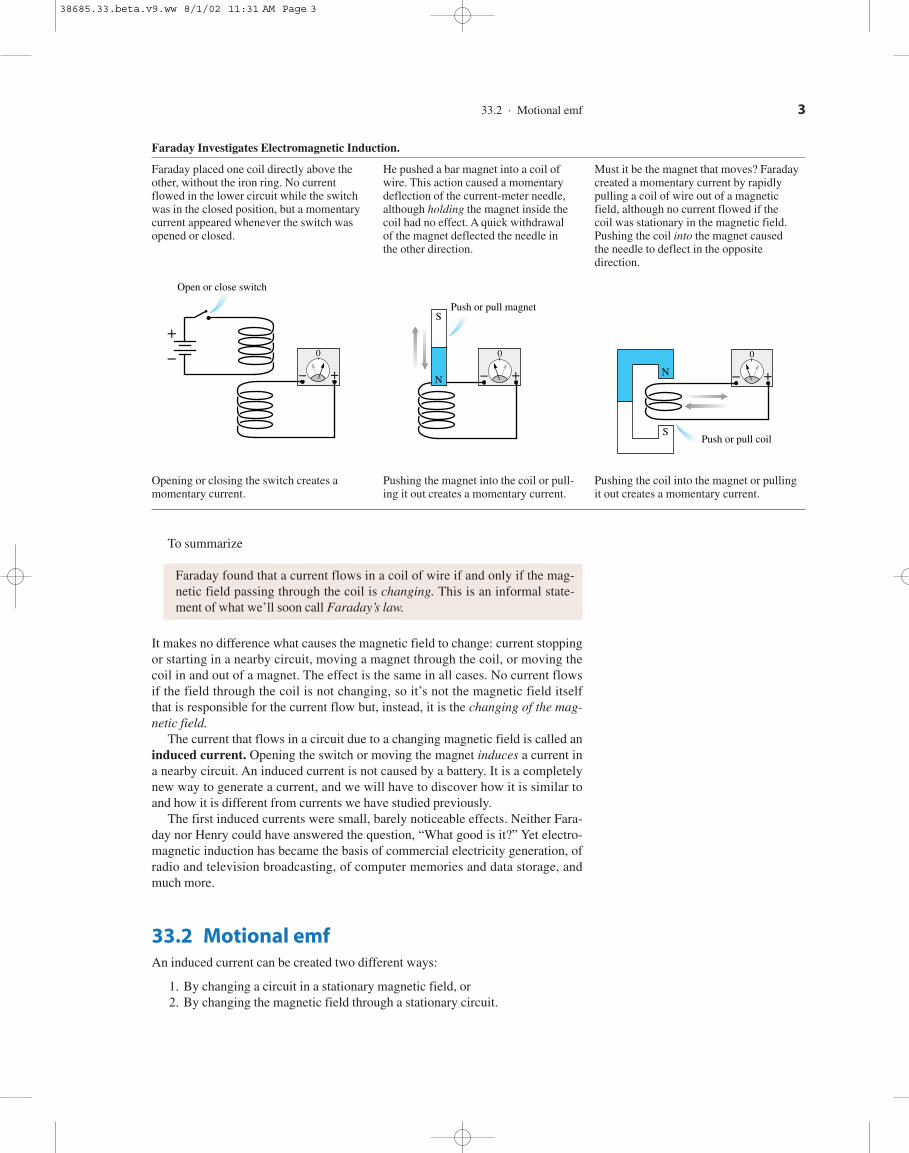
Faraday Investigates Electromagnetic Induction.
Faraday placed one coil directly above the He pushed a bar magnet into a coil of Must it be the magnet that moves? Faraday other, without the iron ring. No current wire. This action caused a momentary created a momentary current by rapidly flowed in the lower circuit while the switch deflection of the current-meter needle, pulling a coil of wire out of a magnetic was in the closed position, but a momentary although holding the magnet inside the field, although no current flowed if the current appeared whenever the switch was coil had no effect. A quick withdrawal coil was stationary in the magnetic field. opened or closed. of the magnet deflected the needle in Pushing the coil into the magnet caused
the other direction. the needle to deflect in the opposite direction.
Opening or closing the switch creates a Pushing the magnet into the coil or pull- Pushing the coil into the magnet or pullingmomentary current. ing it out creates a momentary current. it out creates a momentary current.
��
0
Push or pull coil
N
S
��
0
S
N
Push or pull magnet
�
�
��
0
Open or close switch
38685.33.beta.v9.ww 8/1/02 11:31 AM Page 3

4 C H A P T E R 33 . Electromagnetic Induction
Although the effects are the same, the causes turn out to be different. We’ll startour investigation of electromagnetic induction by looking at situations in whichthe magnetic field is fixed while the circuit moves or changes.
To begin, consider a conductor of length that moves with velocity througha uniform magnetic field as shown in Figure 33.3. The charge carriers insidethe wire also move with velocity so they each experience a magnetic force
For simplicity, we will assume that is perpendicular to inwhich case the strength of the force is This force causes the chargecarriers to move, separating the positive and negative charges and thus creatingan electric field inside the conductor.
The charge carriers continue to move until the electric force exactly balances the magnetic force. This balance happens when the electric fieldstrength is
(33.1)
In other words, the magnetic force on the charge carriers in a moving conductorcreates an electric field inside the conductor.
The electric field, in turn, creates an electric potential difference between thetwo ends of the moving conductor. Figure 33.4a defines a coordinate system inwhich Using the connection between the electric field and the elec-tric potential that we found in Chapter 30,
(33.2)
Thus the motion of the wire through a magnetic field induces a potential differ-ence between the ends of the conductor. The potential difference depends onthe strength of the magnetic field and on the wire’s speed through the field.
There’s an important analogy between this potential difference and the poten-tial difference of a battery. Figure 33.4b reminds you that a battery uses a non-electric force—the charge escalator—to separate positive and negative charges.The emf of the battery was defined as the work performed per charge (W/q) toseparate the charges. An isolated battery, with no current flowing, has a potentialdifference We could refer to a battery, where the charges are separatedby chemical reactions, as a source of chemical emf.
The moving conductor develops a potential difference because of the workdone by magnetic forces to separate the charges. You can think of the movingconductor as a “battery” that stays charged only as long as it keeps moving but“runs down” if it stops. The emf of the conductor is due to its motion, rather than
DVbat 5 E.
E
v/B
DV 5 Vtop 2 Vbottom 5 23/
0Ey dy 5 23
/
0
12vB 2 dy 5 v/B
Er
5 2vB j.
E 5 vB
E 5 vB
0FrE 0 5 qE
0 FrB 0 5 qvB.Br
,v
rFr
B 5 qv
r3 B
r
.v
r,Br
,v
r/
Charge carriers in the wire experience anupward force of magnitude FB 5 qvB. Beingfree to move, positive charges flow upward(or, if you prefer, negative charges downward).
v
FB
�
B into page
�
rr
r
Figure 33.3 The magnetic force on the charge carriers in a moving conductor creates anelectric field inside the conductor.
The charge separation creates an electric field inthe conductor. E increases as more charge flows.
���
���
v
B
E
r
r
r
rThe charge flow continues until the downwardelectric force FE is large enough to balance theupward magnetic force FB. Then the net forceon a charge is zero and the current ceases.
������
������
v
FB
B
FE
�
r
r
r
r
r
r
Chemical reactions separate the charges andcause a potential difference between the ends.This is a chemical emf.
(b)
Electric fieldinside the battery.
� ��
� �
� � � � �
DVbatEr
Magnetic forces separate the charges and causea potential difference between the ends. This isa motional emf.
Electric fieldinside the movingconductor.
�����
�����
v
B
DV 5 v�B
0
�
E
y
(a)
r
rr
Figure 33.4 Two different ways to generatean emf.
38685.33.beta.v9.ww 8/1/02 11:31 AM Page 4

(a) v
�
�
�
�
�
�
�
�
�
�
(b) v
�
�
�
�
�
�
�
�
�
�
(c) v
B out of page
(d) v
� �� �� �� ��
������
�����
(e) vr r r
r
r
33.2 . Motional emf 5
EXAMPLE 33.1 A Battery SubstituteA flashlight battery is 6.0 cm long and has an emf of 1.5V. With what speed must a 6.0-cm-long wire movethrough a 0.10 T magnetic field to create a motional emfof 1.5 V?
Solve: This is a straightforward computation to illustratemotional emf. Using Equation 33.3,
Assess: This might not be a verypractical substitute for a battery, but it would work aslong as the wire continued to move through the field withthis speed.
250 m/s < 500 mph.
v 5E
/B5
1.5 V10.060 m 2 1 0.10 T 2 5 250 m/s
EXAMPLE 33.2 Potential Difference Along a Rotating BarA metal bar of length rotates with angular velocity about a pivot at one end of the bar. A uniform magneticfield is perpendicular to the plane of rotation. What isthe potential difference between the ends of the bar?
Visualize: Figure 33.5 is a pictorial representation of thebar. The magnetic forces on the charge carriers will causethe outer end to be positive with respect to the pivot.
Br
v/
Solve: Even though the bar is rotating, rather than movingin a straight line, the velocity of each charge carrier is per-pendicular to Consequently, the electric field createdinside the bar is exactly that given in Equation 33.1,
But v, the speed of the charge carrier, nowdepends on its distance from the pivot. Recall that inrotational motion the tangential speed at radius r from thecenter of rotation is Thus the electric field at dis-tance r from the pivot is The electric fieldincreases in strength as you move outward along the bar.
The electric field points toward the pivot, so its radialcomponent is If we integrate outward fromthe center, the potential difference between the ends of thebar is
Assess: is the speed at the midpoint of the bar. Thusis which seems reasonable.vmid/B,DV
12 v/
5 23/
0
12vrB 2 dr 5 vB3/
0r dr 5
12 v/2B
DV 5 Vtip 2 Vpivot 5 23/
0Er dr
Er 5 2vrB.Er
E 5 vrB.v 5 vr.
E 5 vB.
Br
,
The electric field strengthincreases with r.
Angular velocity
Speed at distance r is v 5 r.
Pivot
��
��v
B
E
r
�
�
r
r
r
Figure 33.5 Pictorial representation of a bar rotatingin a magnetic field.
to chemical reactions inside, so we can define the motional emf of a conductormoving with velocity to be
(33.3)
A square conductor moves through a uniform magneticfield. Which of the figures shows the correct charge distribution on the conductor?
STOP TO THINK 33.1
E 5 v/B
v
r
38685.33.beta.v9.ww 8/1/02 11:31 AM Page 5

Induced Current in a Circuit
The moving conductor of Figure 33.3 had an emf, but it couldn’t sustain a currentbecause the charges had nowhere to go. It’s like a battery that is disconnectedfrom a circuit. We can change this by including the moving conductor in a circuit.
Figure 33.6 shows a conducting wire sliding with speed v along a U-shapedconducting rail. We’ll assume that the rail is attached to a table and cannot move.The wire and the rail together form a closed conducting loop—a circuit.
Suppose a magnetic field is perpendicular to the plane of the circuit. Chargesin the moving wire will be pushed to the ends of the wire by the magnetic force,just as they were in Figure 33.3, but now the charges can continue to flow aroundthe circuit. That is, the moving wire acts like a battery in a circuit.
The current that flows around the circuit is an induced current. In this exam-ple, the induced current flows counterclockwise. If the total resistance of the cir-cuit is R, the induced current is given by Ohm’s law as
(33.4)
In this situation, the induced current is due to magnetic forces on moving charges.
Is there an induced current in this circuit? If so, in whichdirection does it flow?
We’ve assumed that the wire is moving along the rail at constant speed. It turnsout that we must apply a continuous pulling force to make this happen. Fig-ure 33.7 shows why. The moving wire, which now carries induced current I, is ina magnetic field. You learned in Chapter 32 that a magnetic field exerts a force ona current-carrying wire. According to the right-hand rule, the magnetic force on the moving wire points to the left. This “magnetic drag” will cause the wire toslow down and stop unless we exert an equal but opposite pulling force tokeep the wire moving.
Note � Think about this carefully. As the wire moves to the right, the mag-netic force pushes the charge carriers parallel to the wire. Their motion,as they continue around the circuit, is the induced current I. Now, becausewe have a current, a second magnetic force enters the picture. Thisforce on the current is perpendicular to the wire and acts to slow the wire’smotion. �
The magnitude of the magnetic force on a current-carrying wire was found inChapter 32 to be Using that result, along with Equation 33.4 for theinduced current, we find that the force required to pull the wire with a constantspeed v is
(33.5)Fpull 5 Fmag 5 I/B 5 1 v/B
R 2/B 5v/2B2
R
Fmag 5 I/B.
Fr
mag
Fr
B
Fr
pull
Fr
mag
Fr
pull
v Brr
STOP TO THINK 33.2
I 5E
R5
v/B
R
Br
6 C H A P T E R 33 . Electromagnetic Induction
v
I
I
B
Conducting rail. Fixedto table and doesn’t move.
Negative endof wire
Positive end of wire Moving wire��
��
The charge carriers flowaround the conducting loopas an induced current.
The charge carriers in the wireare pushed upward by themagnetic force.
�r r
1.
2.
Figure 33.6 A current is induced in the circuit as the wire moves through a magnetic field.
I
The magnetic force onthe current-carryingwire is opposite the motion.
FmagFpull
A pulling force to the right mustbalance the magnetic force to keepthe wire moving at constant speed.This force does work on the circuit.
The induced current flowsthrough the moving wire.
�r
r
Figure 33.7 A pulling force is needed tomove the wire to the right.
38685.33.beta.v9.ww 8/1/02 11:31 AM Page 6

Energy Considerations
The environment must do work on the wire to pull it. What happens to the energytransferred to the wire by this work? Is energy conserved as the wire moves alongthe rail? It will be easier to answer this question if we think about power ratherthan work. Power is the rate at which work is done on the wire. You learned inChapter 11 that the power exerted by a force pushing or pulling an object withvelocity v is The power provided to the circuit by pulling on the wire is
(33.6)
This is the rate at which energy is added to the circuit by the pulling force.But the circuit also dissipates energy by transforming electric energy into the
thermal energy of the wires and components, heating them up. You learned inChapter 31 that the power dissipated by current I flowing through resistance R is
Equation 33.4 for the induced current I gives us the power dissipated bythe circuit of Figure 33.6:
(33.7)
You can see that Equations 33.6 and 33.7 are identical. The rate at which work isdone on the circuit exactly balances the rate at which energy is dissipated. Thusenergy is conserved.
If you have to pull on the wire to get it to move to the right, you might thinkthat it would spring back to the left on its own. Figure 33.8 shows the same circuitwith the wire moving to the left. In this case, you must push the wire to the left to keep it moving. The magnetic force is always opposite to the wire’s directionof motion.
In both Figure 33.7, where the wire is pulled, and Figure 33.8, where it ispushed, a mechanical force is used to create a current. In other words, we have aconversion of mechanical energy to electric energy. A device that convertsmechanical energy to electric energy is called a generator. The slide-wire circuitsof Figure 33.7 and 33.8 are simple examples of a generator. We will look at morepractical examples of generators later in the chapter.
We can summarize our analysis as follows:
1. Pulling or pushing the wire through the magnetic field at speed v creates amotional emf in the wire and induces a current to flow in thecircuit.
2. To keep the wire moving at constant speed, a pulling or pushing force mustbalance the magnetic force on the wire. This force does work on the circuit.
3. The work done by the pulling or pushing force exactly balances the energydissipated by the current as it flows through the resistance of the circuit.
I 5 E/RE
Pdissipated 5 I 2R 5v2/2B2
R
P 5 I 2R.
Pinput 5 Fpull v 5v2/2B2
R
P 5 Fv.
33.2 . Motional emf 7
FmagFpush
I
I
The induced currentflows clockwise.
The magnetic forceon the current-carryingwire is to the right.
The magnetic force on thecharge carriers is down.
�
�
r r
1.
2.
3.
Figure 33.8 A pushing force is needed tomove the wire to the left.
EXAMPLE 33.3 Lighting a BulbFigure 33.9 shows a circuit consisting of a flashlight bulb,rated 3.0 V/1.5 W, and ideal wires with no resistance. Theright wire of the circuit, which is 10 cm long, is pulled atconstant speed v through a perpendicular magnetic fieldof strength 0.10 T. a. What speed must the wire have tolight the bulb to full brightness? b. What force is neededto keep the wire moving?
3 V1.5 W
10 cm
0.1 T
vr
Figure 33.9 Circuit of Example 33.3.
38685.33.beta.v9.ww 8/1/02 11:31 AM Page 7

Eddy Currents
Figure 33.10 shows a rigid square loop of wire between the poles of a magnet.The upper pole is a north pole, so the magnetic field points downward and is con-fined to the region between the poles. The magnetic field in Figure 33.10a, passesthrough the loop, but the wires are not in the field. None of the charge carriers inthe wire experience a magnetic force, so there is no induced current and it takesno force to pull the loop to the right.
But when the left edge of the loop enters the field, as shown in Figure 33.10b,the magnetic force on the charge carriers induces a current to flow around theloop. The magnetic field then exerts a retarding magnetic force on this current, soa pulling force must be exerted to pull the loop out of the magnetic field. Note thatthe wire, typically copper, is not a magnetic material. A piece of the wire heldnear the magnet would feel no force. Nor would a force be required to pull thewire out if there were a gap in the loop, breaking the circuit and preventing a cur-rent from flowing. It is the induced current in the complete loop that experiencesthe retarding force of the magnetic field.
Figure 33.11 is an alternative way of viewing the situation. Pulling the loop outof the field is like pulling a magnet off the refrigerator door. Regardless of whichway you look at it, a force is required to pull the loop out of the magnetic field.
8 C H A P T E R 33 . Electromagnetic Induction
Model: The moving wire will be treated as a source ofmotional emf.
Visualize: The direction of the magnetic force on thecharge carriers, will cause the inducedcurrent to flow counterclockwise.
Solve: a. The bulb’s rating of 3.0 V/1.5 W means that atfull brightness it will dissipate 1.5 W at a potential differ-ence of 3.0 V. Because the power is related to the voltageand current by the current causing full bright-ness is
The bulb’s resistance, which is the total resistance of thecircuit, is
R 5DV
I5
3.0 V
0.50 A5 6.0 V
I 5P
DV5
1.5 W
3.0 V5 0.50 A
P 5 IDV,
Fr
B 5 qv
r3 B
r
,
Equation 33.5 gives the speed needed to induce thiscurrent:
You can confirm from Equation 33.6 that the inputpower at this speed is 1.5 W. b. From Equation 33.5, the pulling force must be
You can also obtain this result from
Assess: Example 33.1 showed that high speeds areneeded to produce significant potential difference. Thus300 m/s is not surprising. The pulling force is not verylarge, but even a small force can deliver large amounts ofpower when v is large.P 5 Fv
Fpull 5 P/v.
Fpull 5v/2B2
R5 5.0 3 1023 N
v 5IR
/B5
10.50 A 2 16.0 V 210.10 m 2 1 0.10 T 2 5 300 m/s
No force is needed topull the loop whenthe wires are outside the magnetic field.
(a)
v S
Wire loopN
r
Figure 33.10 Pulling a loop of wire out ofa magnetic field.
An induced current flowsaround the loop.
Opposite poles attract, so amagnetic force pulls the looptoward the magnet. An externalforce is needed to pull the loopout of the magnetic field.
Magnetic field ofinduced current.
FpullBv
The current is a magneticdipole. The dipole’s south poleis above the loop, the northpole below.
N
S
Magnet
N
S
Fmag
Fmag
r
r
r
r
r
1.
2.
3.
Figure 33.11 Another way to think about pulling a loop out of a magnetic field.
Induced current
(b)
Fpull
Fmag
v
I
N
S A pulling force is needed to balance the magnetic force on the inducedcurrent.
r
r
r
38685.33.beta.v9.ww 8/1/02 11:31 AM Page 8

These ideas have interesting implications. Consider pulling a sheet of metalthrough a magnetic field, as shown in Figure 33.12a. The metal, we will assume,is not a magnetic material, so it experiences no magnetic force if it is at rest. Thecharge carriers in the metal experience a magnetic force as they move betweenthe pole tips of the magnet. A current is induced, just as in the loop of wire, buthere the currents do not have wires to define their path. As a consequence, two“whirlpools” of current begin to circulate in the metal. These spread-out currentwhirlpools in a solid metal are called eddy currents.
Figure 33.12b shows the situation if we look down from the north pole of themagnet toward the south pole. There is a magnetic force on the eddy current as itflows between the pole tips. This force is to the left, acting as a retarding force.Thus an external force is required to pull the metal through a magnetic field. If thepulling force ceases, the retarding magnetic force quickly causes the metal todecelerate until it stops. Eddy currents are often undesirable. The power dissipa-tion of the eddy currents can cause unwanted heating, and the magnetic forces onthe eddy currents means that extra energy must be expended to move metals inmagnetic fields. But eddy currents also have important useful applications. Agood example is magnetic braking, which is used in some trains and transit-systemvehicles.
The moving train car has an electromagnet that straddles the rail, as shown inFigure 33.13. During normal travel, no current flows through the electromagnetand there is no magnetic field. To stop the car, a current is switched into the elec-tromagnet. The current creates a strong magnetic field that passes through therail, and the motion of the rail relative to the magnet induces eddy currents in therail. The magnetic force between the electromagnet and the eddy currents acts asa braking force on the magnet and, thus, on the car. Magnetic braking systems arevery efficient, and they have the added advantage that they heat the rail ratherthan the brakes.
A square loop of copper wire is pulled through a magneticfield. Rank order, from strongest to weakest, the pulling forces and that must be applied to keep the loop moving at constant speed.
F3 F4F2
v
F1
v vv
B
rrrr
rr r
r
r
Fr
4Fr
3,Fr
2,Fr
1,STOP TO THINK 33.3
33.2 . Motional emf 9
Fpull
Region between thepermanent magnet’s poles
v
Metal sheet
Magnetic force on the eddy currentsis opposite in direction to v.
(b)
r
r
r
(a)
N
SMetal sheet
Fpull
v
Eddy currents are induced ifa metal sheet is pulled througha magnetic field.
r
r
Figure 33.12 Eddy currents.
Fbrake
v
Rail EddycurrentFbrake
Electromagnet
v
Br
r
r
r
r
Figure 33.13 Magnetic braking systemsare an application of eddy currents.
38685.33.beta.v9.ww 8/1/02 11:31 AM Page 9

33.3 Magnetic FluxWe’ve begun our exploration of electromagnetic induction by analyzing a circuit inwhich one wire moves through a magnetic field. You might be wondering what thishas to do with Faraday’s discovery. Faraday found that a current is induced whenthe amount of magnetic field passing through a coil or a loop of wire changes. Butthat’s exactly what happens as the slide wire moves down the rail in Figure 33.6!As the circuit expands, more magnetic field passes through. It’s time to define moreclearly what we mean by “the amount of field passing through a loop.”
Imagine holding a rectangular loop of wire in front of a fan, as shown in Fig-ure 33.14. The amount of air that flows through the loop depends on the effectivearea of the loop as seen along the direction of flow. You can see from the figurethat the effective area is
(33.8)
where is the tilt angle of the loop. A loop perpendicular to the flow, with has the full area of the loop. This is the orientation for maximum flowthrough the loop. No air at all flows through the loop if it is tilted and you cansee that in this case.Aeff 5 0
90°,Aeff 5 A,
u 5 0°,u
Aeff 5 ab cos u 5 A cos u
10 C H A P T E R 33 . Electromagnetic Induction
Fan
a
a
a
a
a
ab
b
b
b
b cos 0
5 0° 5 90°
Tilt angle
These lengthsare the same
Seen in the direction of airflow:
Aeff 5 ab Aeff 5 ab cos Aeff 5 0
b cos ��
�
�
�
�
�
�
Figure 33.14 The amount of air flowingthrough a loop depends on the effectivearea of the loop.
We can apply this idea to a magnetic field passing through a loop. Figure 33.15shows a loop of area in a uniform magnetic field. Think of these fieldvectors, seen here from behind, as if they were arrows shot into the page. Thedensity of arrows (arrows per ) is proportional to the strength B of the magneticfield; a stronger field would be represented by arrows spaced closer together. Thenumber of arrows passing through a loop of wire depends on two factors:
1. The density of arrows, which is proportional to B, and2. The effective area of the loop.
The angle is the angle between the magnetic field and the axis of the loop. Themaximum number of arrows passes through the loop when it is perpendicular tothe magnetic field No arrows pass through the loop if it is tilted
With this in mind, let’s define the magnetic flux as
(33.9)
The magnetic flux measures the amount of magnetic field passing through a loopof area A if the loop is tilted at angle from the field. The SI unit of magnetic fluxis the weber. From Equation 33.9 you can see that
1 weber 5 1 Wb 5 1 Tm2
u
F 5 Aeff B 5 AB cos u
F90°.1 u 5 0° 2 .
u
A 5 A cos u
m2
A 5 ab
38685.33.beta.v9.ww 8/1/02 11:31 AM Page 10

Equation 33.9 is reminiscent of the vector dot product: With that in mind, let’s define an area vector to be a vector that is perpendicu-lar to a loop of area A and whose magnitude is equal to the area of the loop:
Vector has units of Figure 33.16a shows the area vector for acircular loop of area A.
Figure 33.16b shows a magnetic field passing through a loop. The anglebetween vectors and is the same angle used in Equations 33.8 and 33.9 todefine the effective area and the magnetic flux. So Equation 33.9 really is a dotproduct, and we can define the magnetic flux more concisely as
(33.10)
Writing the flux as a dot product helps make clear how angle is defined: is the angle between the magnetic field and a line perpendicular to the plane of the loop.
uu
F 5 Ar # B
r
Br
Ar
Ar
m2.Ar0Ar 0 5 A.
Ar
Ar # B
r
5 0Ar 0 0 Br 0 cos u.
33.3 . Magnetic Flux 11
a
a
a
aa
bb
b
b
b cos
Axis of loop
b cos 0
0° 90°�
�
�
��
�� 5 90°B
a
Loop perpendicular to field.Maximum number of arrowspass through.
Loop rotated through angle .Fewer arrows pass through.
Loop rotated 90°. No arrowspass through.
Seen in the directionof magnetic field:
These lengthsare the same
r
Br B
r
Figure 33.15 Magnetic field through a loop that is tilted at various angles.
�
�
BA
The angle betweenA and B is the angleat which the loophas been tilted.
The magneticflux throughthe loop isF 5 A # B
(b)r
r r
r
rr
A
The area vector isperpendicular to theloop. Its magnitudeis the area of the loop.
Loop ofarea A
(a)r
Figure 33.16 Magnetic flux can bedefined in terms of an area vector A
r
.
B
A
Pivot
Circular loop
�
r
r
Figure 33.17 A circular loop in a magnetic field.
EXAMPLE 33.4 A Circular Loop Rotating in a Magnetic FieldFigure 33.17 is an edge view of a 10-cm-diameter circu-lar loop rotating in a uniform 0.050 T magnetic field.
What is the magnetic flux through the loop when is and
Solve: The angle is the angle between the loop’s areavector which is perpendicular to the plane of theloop, and the magnetic field Vector has magni-tude Using Equa-tion 33.10 gives the flux:
F 5 Ar # B
r
5 AB cos u 5 d3.93 3 1024 Wb u 5 0°
3.40 3 1024 Wb u 5 30°
1.96 3 1024 Wb u 5 60°
0 Wb u 5 90°
0Ar 0 5 A 5 pr2 5 7.85 3 1023 m2.Ar
Br
.Ar
,u
90°?60°,30°,0°,u
38685.33.beta.v9.ww 8/1/02 11:31 AM Page 11

Magnetic Flux in a Nonuniform Field
Equation 33.10 for the magnetic flux assumes that the field is uniform over thearea of the loop. We can calculate the flux in a nonuniform field, one where thefield strength changes from one edge of the loop to the other, but we’ll need to usecalculus.
Figure 33.18 shows a loop in a nonuniform magnetic field. Imagine dividingthe loop into many small pieces of area dA. The infinitesimal flux through onesuch area, where the magnetic field is is
(33.11)
The total magnetic flux through the loop is the sum of the fluxes through each ofthe small areas. We find that sum by integrating. Thus the total magnetic fluxthrough the loop is
(33.12)
Equation 33.12 is a more general definition of magnetic flux. It may look ratherformidable, so we’ll illustrate its use with an example.
F 5 3area of loop
Br # dA
r
dF 5 Br # dA
r
Br
,dF
12 C H A P T E R 33 . Electromagnetic Induction
B
Loop
Increasing field strength
Small area dA.Flux through thislittle area isdF 5 B # dA
r
r
r
Figure 33.18 A loop in a nonuniformmagnetic field.
EXAMPLE 33.5 Magnetic Flux From the Current in a Long Straight WireThe rectangular loop of Figure 33.19ais 1.0 cm away from a long straight wire. The wire carriesa current of 1.0 A. What is the magnetic flux through theloop?
1.0 cm 3 4.0 cm
Model: We’ll treat the wire as if it were infinitely long.The magnetic field strength of a wire decreases with dis-tance from the wire, so the field is not uniform over thearea of the loop.
Visualize: Using the right-hand rule, we see that the field,as it circles the wire, is perpendicular to the plane of theloop. Figure 33.19b redraws the loop with the field com-ing out of the page and establishes a coordinate system.
Solve: Let the loop have dimensions a and b, as shown,with the near edge at distance c from the wire. The mag-netic field varies with distance x from the wire, but thefield is constant along a line parallel to the wire. Thissuggests dividing the loop into many narrow rectangularstrips of length b and width dx, forming a small area
The magnetic field has the same strength atall points within this small area. One such strip is shownin the figure at position x.
The area vector is perpendicular to the strip (com-ing out of the page), which makes it parallel to
Thus the infinitesimal flux through this littlearea is
where, from Chapter 32, we’ve used as themagnetic field at distance x from a long straight wire.Integrating “over the area of the loop” means to integratefrom the near edge of the loop at to the far edge at
Thus
F 5m0 Ib
2p 3
c1a
c
dxx
5m0 Ib
2p ln x P c1a
c
5m0 Ib
2p ln 1 c 1 a
c 2x 5 c 1 a.
x 5 c
B 5 m0 I/2px
dF 5 Br # dA
r
5 B dA 5 Bb dx 5m0 Ib
2px dx
1 u 5 0° 2 . Br
dAr
dA 5 b dx.
Vector dA is coming out of the page.
I
x
y
Decreasing B
ac
b
B
dx
x
Strip of area dA = b dx at position x.Magnetic flux through this strip is
dF 5 B dA.
(b)
r
r
ALoop
Long straight wire
1.0 cm 1.0 cm
4.0 cm
I
(a) r
Figure 33.19 Magnetic flux through a loop due to the magneticfield of a long straight wire.
38685.33.beta.v9.ww 8/1/02 11:31 AM Page 12

Evaluating for andgives
F 5 5.55 3 1029 Wb
I 5 1.0 Ab 5 0.040 m,a 5 c 5 0.010 m,
33.4 . Lenz’s Law 13
Assess: The flux measures how much of the wire’s mag-netic field passes through the loop, but we had to inte-grate, rather than simply using Equation 33.10, becausethe field is stronger at the near edge of the loop than atthe far edge.
33.4 Lenz’s LawWe started out by looking at a situation in which a moving wire caused a loop toexpand in a magnetic field. This is one way to change the magnetic flux throughthe loop. But Faraday found that a current can be induced by any change in themagnetic flux, no matter how it’s accomplished.
For example, a momentary current is induced in the loop of Figure 33.20 as thebar magnet is pushed toward the loop, increasing the flux through the loop.Pulling the magnet back out of the loop causes the current meter to deflect in theopposite direction. The conducting wires aren’t moving, so this is not a motionalemf. Nonetheless, the induced current is very real.
The German physicist Heinrich Lenz began to study electromagnetic induc-tion after learning of Faraday’s discovery. Three years later, in 1834, Lenzannounced a rule for determining the direction of the induced current. We nowcall his rule Lenz’s law, and it can be stated as follows:
LENZ’S LAW An induced current flows around a closed, conducting loop ifand only if the magnetic flux through the loop is changing. The induced cur-rent flows in a direction such that the induced magnetic field opposes thechange in the flux.
Lenz’s law is rather subtle, and it takes some practice to see how to apply it.
Note � One difficulty with Lenz’s law is the term flux. In everyday lan-guage, the word flux already implies that something is changing. Think ofthe phrase, “The situation is in flux.” Not so in physics, where flux means“passes through.” A steady magnetic field through a loop creates a steady,unchanging magnetic flux. �
Lenz’s law tells us to look for situations where the flux is changing. This canhappen in one of three ways.
1. The magnetic field through the loop changes (increases or decreases), or2. The loop changes ( in area or angle), or3. The loop is moving into or out of a magnetic field.
Lenz’s law depends on an idea that we hinted at in our discussion of eddy cur-rents. If a current is induced to flow around a loop, that current generates its ownmagnetic field This is the induced magnetic field of Lenz’s law. Youlearned in Chapter 32 how to use the right-hand rule to determine the direction ofthis induced magnetic field.
In Figure 33.20, pushing the bar magnet into the loop causes the magnetic fluxto increase in the downward direction. To oppose the change in flux, which iswhat Lenz’s law requires, the loop itself needs to generate the upward-pointingmagnetic field of Figure 33.21. The induced magnetic field at the center of theloop will point upward if the current flows counterclockwise. Thus pushing thenorth end of a bar magnet toward the loop induces a current that flows around the
Br
induced .
��
Current meter
In0
B
A bar magnet pushed into a loopincreases the flux through the loopand induces a current to flow.
Does the induced current flowclockwise or counterclockwise?
N
S
r
Figure 33.20 Pushing a bar magnet towardthe loop induces a current to flow.
��
Current meter0
B
Inducedcurrent
Binduced
The loop needs togenerate an upward-pointing magneticfield to oppose thechange in flux.
According to theright-hand rule, acounterclockwisecurrent is needed toinduce an upwardpointing magneticfield.
The flux throughthe loop increasesdownward asthe magnetapproaches.
N
S
r
r
2.
1.
3.
Figure 33.21 The induced current flowscounterclockwise.
38685.33.beta.v9.ww 8/1/02 11:31 AM Page 13

loop in a counterclockwise direction. Once the magnet stops moving, the inducedcurrent stops flowing.
Now suppose the bar magnet is pulled back away from the loop, as shown inFigure 33.22a. There is a downward magnetic flux through the loop, but the fluxdecreases as the magnet moves away. According to Lenz’s law, the induced mag-netic field of the loop will oppose this decrease. To do so, the induced field needsto point in the downward direction, as shown in Figure 33.22b. Thus as the mag-net is withdrawn, the induced current flows clockwise, opposite to the inducedcurrent of Figure 33.21.
Note � Notice that the magnetic field of the bar magnet is pointing down-ward in both Figures 33.21 and 33.22. It is not the flux due to the magnetthat the induced current opposes, but the change in the flux. This is a subtlebut critical distinction. If the induced current opposed the flux itself, thecurrent in both Figures 33.21 and 33.22 would flow counterclockwise togenerate an upward magnetic field. But that’s not what happens. When thefield of the magnet points down and is increasing, the induced currentopposes the increase by generating an upward field. When the field of themagnet points down but is decreasing, the induced current opposes thedecrease by generating a downward field. �
Figure 33.23 shows six basic situations. The magnetic field can point either upor down through the loop. For each, the flux can either increase, hold steady, ordecrease in strength. These observations form the basis for a set of rules aboutusing Lenz’s law.
14 C H A P T E R 33 . Electromagnetic Induction
��
Current meter
Out0
B
The bar magnet is movingaway from the loop.
N
S
(a)
r
T(a)
��
Current meter0
Inducedcurrent
Binduced
A downward pointing field isneeded to oppose the change.
Downward fluxis decreasing.
A downward pointing field isinduced by a clockwise current.
(b)
r
2.
1.
3.
Figure 33.22 Pulling the magnet awayinduces a clockwise current.
No inducedcurrent
B
B up and steadyNo change in fluxNo induced fieldNo induced current
r
r
1.2.3.4.
No inducedcurrent
B
B down and steadyNo change in fluxNo induced fieldNo induced current
r
r
1.2.3.4.
Inducedcurrent
Binduced
Inducedcurrent
Binduced
B
B
B up and increasingChange in flux cInduced field TInduced current cw
B down and increasingChange in flux TInduced field cInduced current ccw
r
r
r
r
r
r
1.2.3.4.
1.2.3.4.
Inducedcurrent
Binduced
B
B up and decreasingChange in flux TInduced field cInduced current ccw
r
r
r
1.2.3.4.
Inducedcurrent
Binduced
B
B down and decreasingChange in flux cInduced field TInduced current cw
r
r
r
1.2.3.4.
Figure 33.23 The induced current for six different situations.
TACTICS BOX 33.1 Using Lenz’s Law� Determine the direction of the applied magnetic field. The field must
pass through the closed loop.� Determine how the flux is changing. Is it increasing, decreasing, or
staying the same?
38685.33.beta.v9.ww 8/1/02 11:31 AM Page 14

� Determine the direction of an induced magnetic field that willoppose the change in the flux.
Increasing flux: the induced magnetic field points opposite theapplied magnetic field.
Decreasing flux: the induced magnetic field points in the samedirection as the applied magnetic field.
Steady flux: there is no induced magnetic field.
� Determine the direction of the induced current. Use the right-handrule to determine the current direction that generates the induced mag-netic field you found in step 3.
Let’s look at some examples.
33.4 . Lenz’s Law 15
EXAMPLE 33.6 Lenz’s Law 1The switch in the circuit of Figure 33.24a has been closedfor a long time. What happens in the lower loop when theswitch is opened?
Model: We’ll use the right-hand rule to find the magneticfields of current loops.
Visualize and Solve: Figure 33.24b shows the four stepsof using Lenz’s law. Opening the switch induces a coun-terclockwise current in the lower loop. This is a momen-tary current, lasting only until the magnetic field of theupper loop drops to zero.
Assess: The conclusion is consistent with Figure 33.23.
��
0
(a)
��
0
B
Switch opens
Induced current
Binduced
(b)
Magnetic field of uppercircuit is up.
Flux through loop isup and decreasing.
Induced field needs topoint upward to opposethe change in flux.
A counterclockwisecurrent induces anupward magnetic field.
1
2
3 4
r
r
Figure 33.24 Circuits of Example 33.6.
EXAMPLE 33.7 Lenz’s Law 2Figure 33.25a shows two solenoids facing each other.When the switch for coil 1 is closed, does the inducedcurrent in coil 2 flow from right to left or from left toright through the current meter?
��
0
(a)
��
0
B Binduced
Switchcloses Induced current
I
Magnetic field ofsolenoid is left.
Flux through coil isleft and increasing.
Induced field needs topoint right to opposethe change in flux.
1 2 3
4 Current directionthat induces afield to the right.
(b)
r r
Figure 33.25 The two solenoids of Example 33.7.
Model: We’ll use the right-hand rule to find the mag-netic fields of solenoids.
38685.33.beta.v9.ww 8/1/02 11:31 AM Page 15

A current-carrying wire is pulled awayfrom a conducting loop in the direction shown. As the wire ismoving, is there a clockwise current around the loop, a counter-clockwise current, or no current?
STOP TO THINK 33.4
16 C H A P T E R 33 . Electromagnetic Induction
Visualize: It is very important to look at the direction inwhich a solenoid is wound around the cylinder. Noticethat the two solenoids in Figure 33.25a are wound inopposite directions.
Solve: Figure 33.24b shows the four steps of usingLenz’s law. Closing the switch induces a current that
flows from right to left through the current meter. Theinduced current is only momentary. It lasts only until thefield from coil 1 reaches full strength and is no longerchanging.
Assess: The conclusion is consistent with Figure 33.23.
EXAMPLE 33.8 A Rotating LoopThe loop of wire in Figure 33.26 was initially in the xy-plane, parallel to the magnetic field. It is suddenly rotated
about the y-axis until it is in the yz-plane, perpendicu-lar to the magnetic field. What direction is the inducedcurrent as the loop rotates?
Solve: Unlike the magnetic fields in the previous exam-ples, this magnetic field is constant and unchanging.Nonetheless, the flux through the loop changes as itrotates. To use Lenz’s law,
� The applied magnetic field points to the right.� Initially the flux is but after rotating the flux is
toward the right, where A is the loop area.This is an increasing flux to the right.
� To oppose this increase in the flux, the induced mag-netic field must have an x-component toward the left.
� This will be the case if an induced current flows in aclockwise direction, as seen from the perspective ofFigure 33.26.
F 5 ABF 5 0,
90°
x
y
z
Induced current
B
B
Initial position of loop
Loop rotatesabout y-axis
r
r
Figure 33.26 A current is induced in a loop as the looprotates in a constant magnetic field.
v
I
v
33.5 Faraday’s LawFaraday discovered that a current is induced when the magnetic flux through aconducting loop changes. Lenz’s law allows us to find the direction of theinduced current. To put electromagnetic induction to practical use, we also needto know the size of the induced current.
Currents don’t start flowing spontaneously. A current requires an emf to pro-vide the energy. We started our analysis of induced currents with circuits in whichthere is a motional emf. The motional emf can be understood in terms of magneticforces on moving charges. But we’ve also seen that a current can be induced bychanging the magnetic field through a stationary circuit, a circuit in which there isno motion. There must be an emf in this circuit, even though the mechanism forthis emf is not yet clear.
38685.33.beta.v9.ww 8/1/02 11:31 AM Page 16

The emf associated with a changing magnetic flux, regardless of what causesthe change, is called an induced emf Then, if there is a complete circuit havingresistance R, a current
(33.13)
flows in the wire as a consequence of the induced emf. The direction of the cur-rent flow is given by Lenz’s law. The last piece of information we need is the sizeof the induced emf
The research of Faraday and others eventually led to the discovery of the basiclaw of electromagnetic induction, which we now call Faraday’s law. Faraday’slaw is a new law of physics, not derivable from any previous laws you have stud-ied. It states:
FARADAY’S LAW An emf is induced in a conducting loop if the magneticflux through the loop changes. The magnitude of the emf is
(33.14)
and the direction of the emf is such as to drive an induced current in thedirection given by Lenz’s law.
In other words, the induced emf is the rate of change of the magnetic flux throughthe loop.
As a corollary to Faraday’s law, a coil of wire consisting of N turns in a chang-ing magnetic field acts like N batteries in series. The induced emf of each of thecoils adds, so the induced emf of the entire coil is
(Faraday’s law for an N-turn coil) (33.15)
As a first example of using Faraday’s law, return to the situation of Figure 33.6,where a wire moves through a magnetic field by sliding on a U-shaped conduct-ing rail. Figure 33.27 shows the circuit again. The magnetic field is perpendicu-lar to the plane of the conducting loop, so and the magnetic flux is
where A is the area of the loop. If the slide wire is distance x from theend, the area is and the flux at that instant of time is
(33.16)
The flux through the loop increases as the wire moves. According to Faraday’slaw, the induced emf is
(33.17)
where the wire’s velocity is Using Equation 33.13 gives the inducedcurrent:
(33.18)
The flux is increasing into the loop, so the induced magnetic field will opposethis increase by pointing out of the loop. This requires the induced current to flowcounterclockwise around the loop. Faraday’s law leads us to the conclusion thatan induced current will flow around the loop in a counterclockwisedirection. This is exactly the conclusion we reached in Section 33.2, where we
I 5 v/B/R
I 5E
R5
v/B
R
v 5 dx/dt.
E 5 P dF
dt P 5d
dt 1 x/B 2 5
dx
dt /B 5 v/B
F 5 AB 5 x/B
A 5 x/F 5 AB,
u 5 0°Br
Ecoil 5 N P dFper coil
dt P
E 5 P dF
dt PE
E.
Iinduced 5E
R
E.
33.5 . Faraday’s Law 17
x
�
Induced current
Magnetic flux F 5 AB 5 x�B
v
I
I
Br r
Figure 33.27 The magnetic flux throughthe loop increases as the slide wire moves.
38685.33.beta.v9.ww 8/1/02 11:31 AM Page 17

18 C H A P T E R 33 . Electromagnetic Induction
EXAMPLE 33.9 Electromagnetic Induction in a CircularLoopThe magnetic field of Figure 33.28 decreases from 1.0 Tto 0.4 T in 1.2 s. A 6.0-cm-diameter conducting loop witha resistance of is perpendicular to What arethe size and direction of the current induced in the loop?
Br
.0.010 V
Solve: The magnetic field is perpendicular to the plane ofthe loop, so and the magnetic flux is
The radius doesn’t change with time,but B does. According to Faraday’s law, the induced emf is
The rate at which the magnetic field changes is
dB/dt is negative because the field is decreasing, but allwe need for Faraday’s law is the absolute value. Thus
The induced current that flows due to this emf is
The decreasing magnetic field causes a 0.141 A current toflow clockwise for 1.2 s.
Assess: We don’t have much to go on for assessing theresult. The emf is quite small, but, because the resistanceof metal wires is also very small, the current is respectable.We know that electromagnetic induction produces currentslarge enough for practical applications, so this result seemsplausible.
I 5E
R5
0.00141 V
0.010 V5 0.141 A
E 5 pr 2 P dB
dt P 5 p 10.030 m 2 2 10.50 T/s 2 5 0.00141 V
dB
dt5
DB
Dt5
20.60 T
1.2 s5 20.50 T/s
E 5 P dF
dt P 5 P d 1pr 2B 2dt P 5 pr 2 P dB
dt PF 5 AB 5 pr 2B.
u 5 0°
6.0 cm
B
B decreases from 1.0 Tto 0.4 T in 1.2 s.
R 5 0.010 V
r
Figure 33.28 A circular conductingloop in a decreasing magnetic field.
Model: Assume that B decreases linearly with time.
Visualize: The magnetic flux is into the page anddecreasing. To oppose the change in the flux, the inducedfield needs to point into the page. This will be true if theinduced current flows around the loop in a clockwisedirection.
analyzed the situation from the perspective of magnetic forces on moving chargecarriers. Faraday’s law confirms what we already knew but, at least in this case,doesn’t seem to offer anything new.
Using Faraday’s Law
Most electromagnetic induction problems can be solved with a four-step strategy.
Problem-Solving Strategy 33.1Electromagnetic Induction
Model: Make simplifying assumptions.
Visualize: Draw a picture or a circuit diagram. Use Lenz’s law to deter-mine the direction of the induced current.
Solve: The mathematical representation is based on Faraday’s law
For a N-turn coil, multiply by N. The size of the induced current is
Assess: Check that your result has the correct units, is reasonable, andanswers the question.
I 5 E/R.
E 5 P dF
dt P
38685.33.beta.v9.ww 8/1/02 11:31 AM Page 18

EXAMPLE 33.10 Electromagnetic Induction in a Solenoid.A 2.0-cm-diameter loop of wire with a resistance of
is placed in the center of a solenoid. The solenoid,shown in Figure 33.29a, is 4.0 cm in diameter, 20 cm long,and wrapped with 1000 turns of wire. Figure 33.29b showsthe current through the solenoid as a function of time as thesolenoid is “powered up.” A positive current is defined asone that flows clockwise when seen from the left. Find thecurrent in the loop as a function of time and show the resultas a graph.
0.010 V
33.5 . Faraday’s Law 19
a negative current. There’s no change in the flux duringthe next two seconds, so the induced current is zero.
Solution. Now we’re ready to use Faraday’s law tofind the magnitude of the current. Because the field isuniform inside the solenoid and perpendicular to theloop the flux is where
is the area of the loop (not the area of thesolenoid). The field of a long solenoid of length wasfound in Chapter 32 to be
The flux through the loop when the solenoid current is is thus
The changing flux creates an induced emf that is givenby Faraday’s law:
From the slope of the graph, we find
Thus the induced emf is
Finally, the current induced in the loop is
where the negative sign comes from Lenz’s law. Thisresult is shown in Figure 33.30.
Iloop 5E
R5 b21.97 mA 0.0 s , t , 1.0 s
0 mA 1.0 s , t , 3.0 s
E 5 b1.97 3 1025 V 0.0 s , t , 1.0 s
0 V 1.0 s , t , 3.0 s
P dIsol
dt P 5 b10 A/s 0.0 s , t , 1.0 s
0 1.0 s , t , 3.0 s
E 5 P dF
dt P 5m0 AN
/ P dIsol
dt P 5 1.97 3 1026 P dIsol
dt PE
F 5m0 ANIsol
/
Isol
B 5m0 NIsol
/
/3.14 3 1024 m2
A 5 pr2 5F 5 AB,1 u 5 0° 2 ,
20 cm, 1000 turns
4.0 cm
2.0-cm-diameter loop
Positivecurrent
(a)
B r
t (s)
Solenoid currentIsol(A)
010 2 3
10
(b)
Figure 33.29 A loop inside a solenoid.
Model. The solenoid’s length is much greater than itsdiameter, so the field near the center should be that of along solenoid.
Visualize. The magnetic field of the solenoid creates amagnetic flux through the loop of wire. The solenoid cur-rent is always positive, meaning that it flows clockwiseas seen from the left. Consequently, from the right-handrule, the magnetic field inside the solenoid always pointsto the right. During the first second, while the solenoidcurrent is increasing, the flux through the loop is to theright and increasing. To oppose the change in the flux,the loop’s induced magnetic field must point to the left.Thus, again using the right-hand rule, the induced currentmust flow counterclockwise as seen from the left. This is
–2
0
2
t (s)21 3
Iloop (mA)
Figure 33.30 The induced current in the loop.
What Does Faraday’s Law Tell Us?
The induced current in the slide-wire circuit of Figure 33.27 can be understood asa motional emf due to magnetic forces on moving charges. We had not anticipatedthis kind of current in Chapter 32, but it takes no new laws of physics to under-stand it.
38685.33.beta.v9.ww 8/1/02 11:31 AM Page 19
The induced currents in Examples 33.9 and 33.10 are different. We cannotexplain or predict these induced currents on the basis of previous laws or princi-ples. This is new physics.
Faraday recognized that all induced currents are associated with a changingmagnetic flux. There are two fundamentally different ways to change the mag-netic flux through a conducting loop:
1. The loop can move or expand or rotate, creating a motional emf.2. The magnetic field can change.
We can see both of these if we write Faraday’s law as
(33.19)
The first term on the right side represents a motional emf. The magnetic flux changesbecause the loop itself is changing. This term includes not only situations like theslide-wire circuit, where the area A changes, but also loops that rotate in a magneticfield. The physical area of a rotating loop does not change, but the area vectordoes. The loop’s motion causes magnetic forces on the charge carriers in the loop.
The second term on the right side is the new physics in Faraday’s law. It saysthat an emf can also be created simply by changing a magnetic field, even if noth-ing is moving. This was the case in Examples 33.9 and 33.10.
Faraday’s law tells us that the induced emf is simply the rate of change of themagnetic flux through the loop, regardless of what causes the flux to change. The“old physics” of motional emf is included within Faraday’s law as one way ofchanging the flux, but Faraday’s law then goes on to say that any other way ofchanging the flux will have the same result.
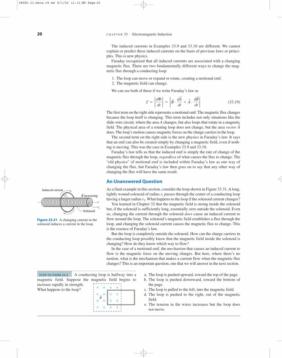
An Unanswered Question
As a final example in this section, consider the loop shown in Figure 33.31. A long,tightly wound solenoid of radius passes through the center of a conducting loophaving a larger radius What happens to the loop if the solenoid current changes?
You learned in Chapter 32 that the magnetic field is strong inside the solenoidbut, if the solenoid is sufficiently long, essentially zero outside the solenoid. Evenso, changing the current through the solenoid does cause an induced current toflow around the loop. The solenoid’s magnetic field establishes a flux through theloop, and changing the solenoid current causes the magnetic flux to change. Thisis the essence of Faraday’s law.
But the loop is completely outside the solenoid. How can the charge carriers inthe conducting loop possibly know that the magnetic field inside the solenoid ischanging? How do they know which way to flow?
In the case of a motional emf, the mechanism that causes an induced current toflow is the magnetic force on the moving charges. But here, where there’s nomotion, what is the mechanism that makes a current flow when the magnetic fluxchanges? This is an important question, one that we will answer in the next section.
r2 .r1
Ar
E 5 P dF
dt P 5 P Br #
dAr
dt1 A
r #
dBr
dt P
20 C H A P T E R 33 . Electromagnetic Induction
Solenoid
Induced current
B increasing
r1
r2r
Figure 33.31 A changing current in thesolenoid induces a current in the loop.
A conducting loop is halfway into amagnetic field. Suppose the magnetic field begins toincrease rapidly in strength.What happens to the loop?
STOP TO THINK 33.5
Br
a. The loop is pushed upward, toward the top of the page.b. The loop is pushed downward, toward the bottom of
the page.c. The loop is pulled to the left, into the magnetic field.d. The loop is pushed to the right, out of the magnetic
field.e. The tension in the wires increases but the loop does
not move.
38685.33.beta.v9.ww 8/1/02 11:31 AM Page 20

33.6 Induced Fields and Electromagnetic Waves
Faraday’s law is a tool for calculating the strength of an induced current, but oneimportant piece of the puzzle is still missing. What causes the current to flow?That is, what force pushes the charges around the loop against the resistive forcesof the metal?
The only agents that exert forces on charges are electric fields and magneticfields. Magnetic forces are responsible for motional emfs, but magnetic forcescannot explain the current induced in a stationary loop by a changing magneticfield.
Figure 33.32a shows a conducting loop in an increasing magnetic field.According to Lenz’s law, an induced current flows in the counterclockwise direc-tion. But something has to act on the charge carriers to make the current flow, sowe infer that there must be an electric field tangent to the loop at all points. Thiselectric field is caused by the changing magnetic field and is called an inducedelectric field. The induced electric field is the mechanism we were seeking that makes a current flow when there’s a changing magnetic field inside a station-ary loop.
The conducting loop isn’t necessary. The space in which the magnetic fieldis changing is filled with the pinwheel pattern of induced electric fields shownin Figure 33.32b. Current will flow if a conducting path is present, but theinduced electric field is there as a direct consequence of the changing magneticfield.
But this is a rather peculiar electric field. All the electric fields we haveexamined until now have been created by charges. Electric field vectors pointedaway from positive charges and toward negative charges. An electric field cre-ated by charges is called a Coulomb electric field. The induced electric field ofFigure 33.32b is caused not by charges but by a changing magnetic field. It iscalled a non-Coulomb electric field.
So it appears that there are two different ways to create an electric field:
1. A Coulomb electric field is created by positive and negative charges.2. A non-Coulomb electric field is created by a changing magnetic field.
Both exert a force on a charge, and both cause a current to flow in a con-ductor. However, the origins of the fields are very different. Figure 33.33 is aquick summary of the two ways to create and electric field.
We first introduced the idea of a field as a way of thinking about how twocharges exert long-range forces on each other through the emptiness of space.The field may have seemed like a useful pictorial representation of charge inter-actions, but we had little evidence that fields are real, that they actually exist.Now we do. The electric field has shown up in a completely different context,independent of charges, as the explanation of the very real existence of inducedcurrents.
The electric field is not just a pictorial representation; it has a real existence.
Maxwell’s Theory
Faraday’s field concept was capable of explaining the phenomena of electricityand magnetism as they were known in the 1830s and 1840s. But Faraday, despitehis intuitive genius, lacked the mathematical skills to develop a true theory ofelectric and magnetic fields. It was not easy to predict new phenomena or developapplications without a theory.
Fr
5 qEr
33.6 . Induced Fields and Electromagnetic Waves 21
Region of increasing B
Induced electric field E
(b)r
r
II
Inducedcurrent
Conducting loop
E E
Region of increasing B
EE
(a)
r
r r
rr
Figure 33.32 An induced electricfield causes the current to flowaround the loop.
� �A Coulomb electric fieldis created by charges.
E E
A non-Coulomb electric fieldis created by a changingmagnetic field.
E E
B increasing or decreasing
rr
r
r r
Figure 33.33 Two ways to create anelectric field.
38685.33.beta.v9.ww 8/1/02 11:31 AM Page 21

In 1855, less than two years after receiving his undergraduate degree, the Eng-lish physicist James Clerk Maxwell presented a paper titled “On Faraday’s Linesof Force.” In this paper, he began to sketch out how Faraday’s pictorial ideasabout fields could be given a rigorous mathematical basis. Maxwell then spentthe next 10 years developing the mathematical theory of electromagnetism.
Maxwell was troubled by a certain lack of symmetry. Faraday had found that achanging magnetic field creates an induced electric field, a non-Coulomb electricfield not tied to charges. But what, Maxwell began to wonder, about a changingelectric field?
To complete the symmetry, Maxwell proposed that a changing electric fieldcreates an induced magnetic field, a new kind of magnetic field not tied to theexistence of currents. Figure 33.34 shows a region of space where the electricfield is increasing. This region of space, according to Maxwell, is filled with apinwheel pattern of induced magnetic fields. The induced magnetic field lookslike the induced electric field, with and interchanged, except that—for techni-cal reasons—the induced points the opposite way from the induced Althoughthere was no experimental evidence that induced magnetic fields existed,Maxwell went ahead and included them in his electromagnetic field theory. Thiswas an inspired hunch, soon to be vindicated.
Maxwell soon realized that it might be possible to establish self-sustainingelectric and magnetic fields that would be entirely independent of any charges orcurrents. That is, a changing electric field creates a magnetic field whichthen changes in just the right way to recreate the electric field, which thenchanges in just the right way to again recreate the magnetic field, and so on. Thefields are continually recreated through electromagnetic induction without anyreliance on charges or currents.
The mathematics of Maxwell’s theory is difficult, but eventually Maxwell wasable to predict that electric and magnetic fields would be able to sustain them-selves, free from charges and currents, if they took the form of an electromag-netic wave. The wave would have to have a very specific geometry, shown inFigure 33.35, in which and are perpendicular to each other as well as perpen-dicular to the direction of travel. That is, an electromagnetic wave would be atransverse wave.
Furthermore, Maxwell’s theory predicted that the wave would travel withspeed
(33.20)
where is the permittivity constant from Coulomb’s law and is the perme-ability constant from the law of Biot and Savart. Maxwell computed that anelectromagnetic wave, if it existed, would travel with speed
We don’t know Maxwell’s immediate reaction, but it must have been bothshock and excitement. His predicted speed for electromagnetic waves, a predic-tion that came directly from his theory, was none other than the speed of light! Thisagreement could be just a coincidence, but Maxwell didn’t think so. Making a boldleap of imagination, Maxwell concluded that light is an electromagnetic wave.
It took 25 more years for Maxwell’s predictions to be tested. In 1886, the Ger-man physicist Heinrich Hertz discovered how to generate and transmit radiowaves. Two years later, in 1888, he was able to show that radio waves travel at thespeed of light. Maxwell, unfortunately, did not live to see his triumph. He haddied in 1879, at the age of 48.
Chapter 34 will develop some of the mathematical details of Maxwell’s theoryand show how the ideas contained in Faraday’s law lead to electromagneticwaves.
3.00 3 108 m/s.vem wave 5
m0P0
vem wave 51
!P0 m0
Br
Er
Br
,Er
Er
.Br
Br
Er
22 C H A P T E R 33 . Electromagnetic Induction
The velocity of transverse undulationsin our hypothetical medium, calculatedfrom the electromagnetic experiments of Kohlrausch and Weber [who hadmeasured and ], agrees so exactlywith the velocity of light calculated fromthe optical experiments of Fizeau that wecan scarcely avoid the inference that lightconsists of the transverse undulations ofthe same medium which is the cause ofelectric and magnetic phenomena.
James Clerk Maxwell
m 0P0
A changing electric field creates an induced magnetic field.
Inducedmagnetic field B
Region ofincreasing E
rr
r
A changing magnetic field creates an induced electric field.
Inducedelectric field E
Region ofincreasing B
Figure 33.34 Maxwell hypothesized theexistence of induced magnetic fields.
B
B
B
B
E
E
E
E
x
y
z
Direction of propagationat speed vem wave
r
r
r
r
r
r
r
r
Figure 33.35 A self-sustainingelectromagnetic wave.
38685.33.beta.v9.ww 8/1/02 11:31 AM Page 22

33.7 Induced Currents: Three ApplicationsThere are many applications of Faraday’s law and induced currents in moderntechnology. In this section we will look at three: generators, transformers, andmetal detectors.
Generators
We noted in Section 33.2 that a slide wire pulled through a magnetic field on a U-shaped track is a simple generator because it transforms mechanical energyinto electric energy. Figure 33.36 shows a more practical generator. Here a coil ofwire rotates in a magnetic field. Both the field and the area of the loop are con-stant, but the magnetic flux through the loop changes continuously as the looprotates. The induced current is removed from the rotating loop by brushes thatpress up against rotating slip rings.
The flux through the coil is
(33.21)
where is the angular frequency with which the coil rotates. Theinduced emf is given by Faraday’s law,
(33.22)
where N is the number of turns on the coil. We’ve dropped the absolute valuesigns to demonstrate that the sign of alternates between positive and negative.
Because the emf alternates in sign, the current through resistor R alternatesback and forth in direction. Hence the generator of Figure 33.36 is an alternating-current generator, producing what we call an AC voltage.
Ecoil
Ecoil 5 N
dF
dt5 ABN
d
dt 1 cos vt 2 5 2vABN sin vt
1v 5 2pf 2v
F 5 Ar # B
r
5 AB cos u 5 AB cos vt
33.7 . Induced Currents: Three Applications 23
A generator uses electromagnetic inductionto convert the mechanical energy of aspinning turbine into electric energy.
B
I
R
I
I
N
Slip rings
Brushes
S
Permanentmagnet
0 t
1E
2
I
The induced emfas a function of time.
r
Figure 33.36 An alternating-current generator.
EXAMPLE 33.11 An AC GeneratorA coil with area rotates in a 0.010 T magnetic fieldat a frequency of 60 Hz. How many turns are needed togenerate a peak voltage of 160 V?
2.0 m2Solve: The coil’s maximum voltage is found from Equa-tion 33.22:
Emax 5 vABN 5 2p fABN
38685.33.beta.v9.ww 8/1/02 11:31 AM Page 23

The number of turns needed to generate is
A 0.010 T field is modest, so you can see that generat-ing large voltages is not difficult with large coils.Commercial generators use water flowing through a dam
1 2 m2 2 5 21 turns
N 5Emax
2p fAB5
160 V
2p 160 Hz 2 12.0 m2 2 1 0.010 T 2
Emax 5 160 V
24 C H A P T E R 33 . Electromagnetic Induction
or turbines spun by expanding steam to rotate the genera-tor coils. Work is required to rotate the coil, just as workwas required to pull the slide wire in Section 33.2,because the magnetic field exerts retarding forces on thecurrents in the coil. Thus a generator is a device that turnsmotion (mechanical energy) into a current (electricenergy). A generator is the opposite of a motor, whichturns a current into motion.
Transformers
Figure 33.37 shows two coils wrapped on an iron core. The left coil is called theprimary coil. It has turns and is driven by an oscillating voltage Themagnetic field of the primary follows the iron core and passes through the rightcoil, which has turns and is called the secondary coil. The alternating currentthrough the primary coil causes an oscillating magnetic flux through the sec-ondary coil and, hence, an induced emf. The induced emf of the secondary coil isdelivered to resistance R as the oscillating voltage
The current through the primary coil is inversely proportional to the number ofturns: (This relation is a consequence of the coil’s inductance, anidea discussed later in the chapter. But, roughly speaking, the coil’s resistance isproportional to the number of turns, and the current, according to Ohm’s law, isinversely proportional to the resistance.) According to Faraday’s law, the emfinduced in the secondary coil is directly proportional to the number of turns:
Combining these two proportionalities, the secondary voltage of anideal transformer is related to the primary voltage by
(33.23)
Depending on the ratio the voltage delivered to the resistance can betransformed to a higher or a lower voltage than Consequently, this device iscalled a transformer. Transformers are widely used in the commercial generationand transmission of electricity. A step-up transformer, with boosts thevoltage of a generator up to several hundred thousand volts. Delivering powerwith smaller currents at higher voltages reduces losses due to the resistance of thewires. High-voltage transmission lines carry electric power to urban areas, wherestep-down transformers lower the voltage to 120 V.
Metal Detectors
Metal detectors, such as those used in airports for security, seem fairly mysteri-ous. How can they detect the presence of any metal—not just magnetic materialssuch as iron—but not detect plastic or other materials? Metal detectors workbecause of induced currents.
A metal detector, shown in Figure 33.38, consist of two coils: a transmitter coiland a receiver coil. A high-frequency alternating current flows through the trans-mitter coil, generating an alternating magnetic field along the axis. This magneticfield creates a changing flux through the receiver coil and causes an alternatinginduced current. The transmitter and receiver are similar to a transformer.
Now suppose a piece of metal is placed between the transmitter and thereceiver. The alternating magnetic field through the metal induces eddy currentsto flow in a plane parallel to the transmitter and receiver coils. The receiver coil
1N2 V N1 2
N2 W N1 ,
V1 .V2N2/N1 ,
V2 5N2
N1 V1
Esec ~ N2 .
Iprim ~ 1/N1 .
V2 cos vt.
N2
V1 cos vt.N1B
B
R
Magnetic fieldfollows iron core
Iron corePrimary coilN1 turns
Secondary coilN2 turns
V2 cos �tV1 cos �t
r
r
Figure 33.37 A transformer.
Transformers are essential for transportingelectric energy from the power plant tocities and homes.
Metal
Transmitter coil
Receiver coil
Eddy currents in the metalreduce the induced currentin the receiver coil.
Figure 33.38 A metal detector.
38685.33.beta.v9.ww 8/1/02 11:31 AM Page 24

then responds to the superposition of the transmitter’s magnetic field and themagnetic field of the eddy currents. Because the eddy currents attempt to preventthe flux from changing, in accordance with Lenz’s law, the net field at thereceiver decreases when a piece of metal is inserted between the coils. Electroniccircuits detect the current decrease in the receiver coil and set off an alarm. Eddycurrents can’t flow in an insulator, so this device detects only metals.
33.8 InductorsCapacitors were first introduced as devices that produce a uniform electric field.The capacitance (i.e., the capacity to store charge) was defined as the charge-to-voltage ratio We later found that a capacitor stores potential energy
and that this energy is released when the capacitor is discharged.A coil of wire in the form of a solenoid is a device that produces a uniform
magnetic field. Do solenoids in circuits have practical uses, as capacitors do? As astarting point to answering this question, notice that the charge on a capacitor isanalogous to the magnetic flux through a solenoid. That is, a larger diametercapacitor plate holds more charge just as a larger diameter solenoid contains moreflux. Using the definition of capacitance as an analog, let’s define the inductanceL of a magnetic-field device as its flux-to-current ratio
(33.24)
Strictly speaking, this is called self-inductance because the flux we’re consideringis the magnetic flux the device creates in itself when a current flows through it.
The units of inductance are Wb/A. Recalling that this is equiv-alent to It’s convenient to define an SI unit of inductance called thehenry, in honor of Joseph Henry, as
Practical inductances are usually in the range of millihenries (mH) or microhen-ries
Any circuit element can have an inductance by virtue of the fact that currentsproduce magnetic fields. In practice, however, inductance is usually negligibleunless the magnetic field is concentrated, as it is in a solenoid. Consequently, asolenoid or coil of wire is our prototype of inductance. A coil of wire used in a cir-cuit for the purpose of providing inductance is called an inductor. An idealinductor is one for which the wire forming the coil has no electric resistance. Thecircuit symbol for an inductor is .
It’s not hard to find the inductance of a solenoid. In Chapter 32 we found thatthe magnetic field inside a solenoid having N turns and length is
(33.25)
The magnetic flux through each coil is where A is the cross-sectionarea of the solenoid. The total flux through all N coils is
(33.26)
Thus the inductance of the solenoid, using the definition of Equation 33.24, is
(33.27)Lsolenoid 5F
I5
m0 N 2A
/
F 5 NFper coil 5m0 N 2A
/ I
Fper coil 5 AB,
B 5m0 NI
/
/
1mH 2 .1 henry 5 1 H 5 1 T m2/A
T m2/A.1 Wb 5 1 T m2,
L 5F
I
UC 512 C 1DV 2 2
C 5 Q/DV.
33.8 . Inductors 25
38685.33.beta.v9.ww 8/1/02 11:31 AM Page 25

The inductance of a solenoid depends only on its geometry, not at all on thecurrent flowing through it. You may recall that the capacitance of two parallelplates depends only on their geometry, not at all on the potential differencebetween them.
26 C H A P T E R 33 . Electromagnetic Induction
EXAMPLE 33.12 The Length of an InductorAn inductor is made by tightly wrapping 0.30-mm-diameter wire around a 4.0-mm-diameter cylinder. Whatlength cylinder has an inductance of
Solve: The cross-section area of the solenoid is If the wire diameter is d, the number of turns of wire on acylinder of length is Thus the inductance isN 5 //d./
A 5 pr2.
10 mH? The length needed to give inductance is
5 0.057 m 5 5.7 cm
/ 5d2L
m0 pr2 510.00030 m 2 2 11025 H 2
14p 3 1027 T m/A 2 10.0020 m 2 2
L 5 1025 H
L 5m0 N 2A
/5
m0 1 //d 2 2pr2
/5
m0 pr2/d2
The Potential Difference Across an Inductor
An inductor is not very interesting when the current flowing through it is steady.If the inductor is ideal, with the potential difference due to a steady cur-rent is zero. Inductors become important circuit elements when currents arechanging. Figure 33.39a shows a steady current flowing into the left side of aninductor. The solenoid’s magnetic field passes through the coils of the solenoid,establishing a flux.
In Figure 33.39b, the current into the solenoid is increasing. This creates anincreasing flux to the left. According to Lenz’s law, an induced current in the coilswill oppose this increase by creating an induced magnetic field pointing to theright. This requires the induced current to flow opposite the current into the sole-noid. This induced current will carry positive charge carriers to the left until apotential difference is established across the solenoid.
You saw a similar situation in Section 33.2. The induced current in a conductormoving through a magnetic field carried positive charge carriers to the top of thewire and established a potential difference across the conductor. The induced cur-rent in the moving wire was due to magnetic forces on the moving charges. Now,in Figure 33.39b, the induced current is due to the non-Coulomb electric fieldinduced by the changing magnetic field. Nonetheless, the outcome is the same: apotential difference across the conductor.
We can use Faraday’s law to find the potential difference. The emf induced ina coil is
(33.28)
where is the total flux through all the coils. The inductance wasdefined such that so Equation 33.28 becomes
(33.29)
The induced emf is directly proportional to the rate of change of current throughthe coil. We’ll consider the appropriate sign in a moment, but Equation 33.29 givesus the size of the potential difference that is developed across a coil as the currentthrough the coil changes. Note that for a steady, unchanging current.Ecoil 5 0
Ecoil 5 L P dI
dt PF 5 LI,
F 5 NFper coil
Ecoil 5 N P dFper coil
dt P 5 P dF
dt P
DV
R 5 0 V,
(b)
�� DVL
Increasingcurrent
The induced magnetic fieldopposes the change in flux.
The induced current carriespositive charge carriers tothe left and establishes apotential difference acrossthe inductor.
The induced current flowsopposite the solenoid current.
B
Current I
Inductor coil
(a)
Solenoidmagneticfield
r
Figure 33.39 Increasing the currentthrough an inductor.
38685.33.beta.v9.ww 8/1/02 11:31 AM Page 26

Figure 33.40 shows the same inductor, but now the current (still flowing in tothe left side) is decreasing. To oppose the decrease in flux, an induced currentflows in the same direction as the input current. The induced current carries chargeto the right and establishes a potential difference opposite that in Figure 33.39b.
Note � Notice that the induced current does not oppose the current flowingthrough the inductor, which flows from left to right in both Figures 33.39and 33.40. Instead, in accordance with Lenz’s law, the induced currentopposes the change in the current in the solenoid. The practical result is thatit is hard to change the current through an inductor. Any effort to increase ordecrease the current is met with opposition in the form of an opposinginduced current. You can think of the current in an inductor as having iner-tia, wanting to continue what it was doing without change. �
Before we can use inductors in a circuit we need to establish a rule about signsthat is consistent with our earlier circuit analysis. Figure 33.41 first shows currentI passing through a resistor. You learned in Chapter 31 that the potential differ-ence across a resistor is where the minus sign indicates that thepotential decreases in the direction of the current.
We’ll use the same convention for an inductor. The potential difference acrossan inductor, measured along the direction of current flow, is
(33.30)
If the current is increasing the input side of the inductor is morepositive than the output side and the potential decreases in the direction of thecurrent This was the situation in Figure 33.39b. If the current isdecreasing the input side is more negative and the potentialincreases in the direction of the current This was the situation in Fig-ure 33.40.
The potential difference across an inductor can be very large if the currentchanges very abruptly (large dI/dt). Figure 33.42 shows an inductor connectedacross a battery. A large current flows through the inductor, limited only by theinternal resistance of the battery. Suppose the switch is suddenly opened. A verylarge induced voltage is created across the inductor as the current rapidly dropsto zero. This potential difference (plus ) appears across the gap of the switchas it is opened. A large potential difference across a small gap often createsa spark.
Indeed, this is exactly how the spark plugs in your car work. The car’s gener-ator sends a large current through the coil, which is a big inductor. A switch inthe distributor is suddenly opened, breaking the current. The induced voltage,
DVbat
1DVL . 0 2 .1dI/dt , 0 2 ,1DVL , 0 2 .1dI/dt . 0 2 ,
DVL 5 2L
dI
dt
DVR 5 2IR,
33.8 . Inductors 27
Decreasingcurrent
Induced current
The induced current carriespositive charge carriers tothe right. The potentialdifference is opposite thatof Figure 33.39.
Induced field
� �DVL
Figure 33.40 Decreasing the currentthrough an inductor.
�
�
DV 5 2IR
I
The potentialalways decreases.
Resistor Inductor
�
�
DV 5 2L
I
The potential decreases ifthe current is increasing.The potential increases ifthe current is decreasing.
dIdt
Figure 33.41 The potential differenceacross a resistor and an inductor.
Before switch opened
Switch closed
DVbat I
�
�
Figure 33.42 Creating sparks.
As switch opened
Opening
Spark!
DVbat
�
�
I DV 5 2Lis very large
dIdt
38685.33.beta.v9.ww 8/1/02 11:31 AM Page 27

EXAMPLE 33.13 Large Voltage Across an InductorA 1.0 A current flows through a 10 mH inductor coil.What potential difference is induced across the coil if thecurrent drops to zero in
Model: Assume this is an ideal inductor, with and that the current decrease is linear with time.
Solve: The rate of current decrease is
dI
dt<
DI
Dt5
21.0 A
5.0 3 1025 s5 22.0 3 105 A/s
R 5 0 V,
5 ms?
28 C H A P T E R 33 . Electromagnetic Induction
The induced voltage is
Assess: Inductors may be physically small, but they canpack a punch if you try to change the current throughthem too quickly.
5 2000 V
DVL 5 2L
dI
dt< 2 10.010 H 2 122.0 3 105 A/s 2
The potential at a is higher than thepotential at b. Which of the following statements about theinductor current I could be true?
STOP TO THINK 33.6 a. I flows from a to b and is steady.b. I flows from a to b and is increasing.c. I flows from a to b and is decreasing.d. I flows from b to a and is steady.e. I flows from b to a and is increasing.f. I flows from b to a and is decreasing.
typically a few thousand volts, appears across the terminals of the spark plug,creating the spark that ignites the gasoline. A similar phenomenon happens ifyou unplug appliances such as toaster ovens or hair dryers while they are run-ning. The heating coils in these devices have quite a bit of inductance. Suddenlypulling the plug is like opening a switch. The large induced voltage often causesa spark between the plug and the electric outlet.
a bVa . Vb
Energy in Inductors and Magnetic Fields
An inductor, like a capacitor, stores energy that can later be released. It is energyreleased from the coil in your car that becomes the spark of the spark plug. Youlearned in Chapter 31 that electric power is As current passesthrough an inductor, for which the electric power is
(33.31)
is negative because the current is losing electric energy. That energy is beingtransferred to the inductor, which is storing energy at the rate
(33.32)
where we’ve noted that power is the rate of change of energy.We can find the total energy stored in an inductor by integrating Equation 33.32
from where to a final current I. Doing so gives
(33.33)
The potential energy stored in an inductor depends on the square of the currentflowing through it. Notice the analogy with the energy stored in acapacitor.
UC 512 C 1DV 2 2
UL 5 L3I
0IdI 5
12 LI 2
UL 5 0,I 5 0,
dUL
dt5 1LI
dI
dt
UL
Pelec
Pelec 5 IDVL 5 2LI
dI
dt
DVL 5 2L 1 dI/dt 2 ,Pelec 5 IDV.
38685.33.beta.v9.ww 8/1/02 11:31 AM Page 28

In working with circuits we say that the energy is “stored in the inductor.”Strictly speaking, the energy is stored in the inductor’s magnetic field, analogousto how a capacitor stores energy in the electric field. We can use the inductance ofa solenoid, Equation 33.27, to relate the inductor’s energy to the magnetic fieldstrength:
(33.34)
We made the last rearrangement in Equation 33.34 because is the mag-netic field inside the solenoid. Thus
(33.35)
But is the volume inside the solenoid. Dividing by the magnetic fieldenergy density inside the solenoid (energy per ) is
(33.36)
We’ve derived this expression for energy density based on the properties of asolenoid, but it turns out to be the correct expression for the energy density any-where there’s a magnetic field. Compare this to the energy density of an electricfield that we found in Chapter 30.uE 5
12 P0 E2
uB 51
2m0 B2
m3A/,A/
UL 51
2m0 A/B2
m0 NI//
UL 512 LI 2 5
m0 N 2A
2/ I 2 5
1
2m0 A/ 1m0 NI
/ 22
33.9 . LC Circuits 29
Energy in Electric and Magnetic Fields
Electric fields Magnetic fields
A capacitor stores An inductor storesenergy energy
Energy density Energy densityin the field is in the field is
uB 51
2m0 B2uE 5
P0
2 E2
UL 512 LI 2UC 5
12 C 1DV 2 2
EXAMPLE 33.14 Energy Stored in an InductorThe inductor of Example 33.12 was 5.7 cm longand 4.0 mm in diameter. Suppose it carries a 100 mA cur-rent. What are the energy stored in the inductor, the mag-netic energy density, and the magnetic field strength?
Solve: The stored energy is
UL 512 LI 2 5
12 11025 H 2 10.10 A 2 2 5 5.0 3 1028 J
10 mHThe solenoid volume is Using this gives the energy density of the magnetic field:
From Equation 33.36, the magnetic field with this energydensity is
B 5 "2m0 uB 5 4.2 3 1024 T
uB 55.0 3 1028 J
7.16 3 1027 m3 5 0.070 J/m3
1pr2 2 / 5 7.16 3 1027 m3.
33.9 LC CircuitsTelecommunication—radios, televisions, cell phones—is based on electromag-netic signals that oscillate at a well-defined frequency. These oscillations are gen-erated and detected by a simple circuit consisting of an inductor and a capacitor inparallel. This is called an LC circuit. In this section we will learn why an LC cir-cuit oscillates and determine the oscillation frequency.
Figure 33.43 shows a capacitor with initial charge an inductor, and aswitch. The switch has been open for a long time, so no current is flowing. Then,at the switch is closed. How does the circuit respond? Let’s think it throughqualitatively before getting into the mathematics.
As Figure 33.44 shows, the inductor provides a conducting path for discharg-ing the capacitor. However, the discharge current has to flow through the induc-tor, and, as we’ve seen, an inductor resists changes in current. Consequently, thecurrent doesn’t stop when the capacitor charge reaches zero.
t 5 0,
Q0 ,
Switch closes at t 5 0
Initialcharge Q0
C�
�
�
�
�
�
�
�
�
�
�
�L
Figure 33.43 An LC circuit.
38685.33.beta.v9.ww 8/1/02 11:31 AM Page 29

A block attached to a stretched spring is a useful mechanical analogy. Closingthe switch to discharge the capacitor is like releasing the block. But the blockdoesn’t stop when it reaches the origin. Its momentum keeps it going until thespring is fully compressed. Likewise, the current keeps flowing until it hasrecharged the capacitor with the opposite polarization. This process repeats overand over, charging the capacitor first one way, then the other. In other words, thecharge and current oscillate.
The goal of our circuit analysis will be to find expressions showing how thecapacitor charge Q and the inductor current I change with time. As always, ourstarting point for circuit analysis is Kirchhoff’s voltage law, which says that allthe potential differences around a closed loop must sum to zero. Choosing aclockwise direction for I, Kirchhoff’s law is
(33.37)
where Q is the charge on the top plate of the capacitor, and we found the potentialdifference across an inductor in Equation 33.30 above. Using these, Kirchhoff’slaw becomes
(33.38)
Equation 33.38 has two unknowns, Q and I. We need to eliminate one of theunknowns, and we can do so by finding another relation between Q and I. Current
Q
C2 L
dI
dt5 0
DVC 1 DVL 5 0
30 C H A P T E R 33 . Electromagnetic Induction
Q 5 1Q0
I 5 0
Capacitor starts to discharge.
�
�
�
�
�
�
�
�
�
�
�
�
v 5 0
Maximum capacitor charge is likea fully stretched spring.
A
Figure 33.44 The capacitor charge oscillates much like a block attached to a spring.
Q 5 0
I
Current is maximum, but it can’t stop.
Max v
B
Maximum current is like the blockhaving maximum speed.
r
B
Current flows until capacitor is fullyrecharged with the opposite polarization.
Q 5 2Q0
I 5 0
�
�
�
�
�
�
�
�
�
�
�
�
v 5 0
C
Q 5 0
I
Now the discharge current goesthe opposite direction.
Max v
B r
D
Q 5 1Q0
I 5 0
Current flows until the initialcapacitor charge is restored.
�
�
�
�
�
�
�
�
�
�
�
�
v 5 0
A
38685.33.beta.v9.ww 8/1/02 11:31 AM Page 30

is the rate at which charge moves: But the charge flowing through theinductor is charge that was removed from the capacitor. That is, an infinitesimalcharge dq flows through the inductor when the capacitor charge changes by
Thus the current through the inductor is related to the charge on thecapacitor by
(33.39)
Now I is positive when Q is decreasing, as we would expect. This is a subtle butimportant step in the reasoning, one worth thinking about because it appears inother contexts.
Equations 33.38 and 33.39 are two equations in two unknowns. To solve them,we’ll first take the time derivative of Equation 33.39:
(33.40)
We can substitute this result into Equation 33.38:
(33.41)
Now we have an equation for the capacitor charge Q.Equation 33.41 is a second-order differential equation for Q. Fortunately, it is
an equation we’ve seen before and already know how to solve. To see this,rewrite Equation 33.41 as
(33.42)
Recall, from Chapter 14, that the equation of motion for an undamped mass on aspring is
(33.43)
Equation 33.42 is exactly the same equation, with x replaced by Q and replaced by 1/LC. This should be no surprise because we’ve already seen that amass on a spring is a mechanical analog of the LC circuit.
We know the solution to Equation 33.43. It is simple harmonic motionwith angular frequency Thus the solution to Equa-
tion 33.42 must be
(33.44)
where is the initial charge, at and the angular frequency is
(33.45)
The charge on the upper plate of the capacitor oscillates back and forth between(as shown in Figure 33.43) and (the opposite polarization) with period
As the capacitor charge oscillates, so does the current through the inductor.Using Equation 33.39 gives the current flowing through the inductor:
(33.46)
where is the maximum current.Imax 5 vQ0
I 5 2
dQ
dt5 vQ0 sin vt 5 Imax sin vt
T 5 2p/v.2Q01Q0
v 5 Å1
LC
t 5 0,Q0
Q(t) 5 Q0 cos vt
v 5 "k/m .x(t) 5 x0 cos vt
k/m
d2x
dt 2 5 2
km
x
d2Q
dt2 5 2
1
LC Q
Q
C1 L
d2Q
dt2 5 0
dI
dt5
d
dt 12
dQ
dt 2 5 2
d2Q
dt2
I 5 2
dQ
dt
dQ 5 2dq.
I 5 dq/dt.
33.9 . LC Circuits 31
38685.33.beta.v9.ww 8/1/02 11:31 AM Page 31

An LC circuit is an electric oscillator, oscillating at frequency Fig-ure 33.45 shows graphs of the capacitor charge Q and the inductor current I asfunctions of time. The letters over the graph match the labels in Figure 33.44, andyou should compare the two. Notice that Q and I are out of phase. The currentis zero when the capacitor is fully charged, as expected, and the charge is zerowhen the current is maximum.
EXAMPLE 33.15 An AM Radio OscillatorYou have a 1.0 mH inductor. What capacitor should you choose to make anoscillator with a frequency of 920 KHz? (This frequency is near the centerof the AM radio band.)
Solve: The angular frequency is UsingEquation 33.45 for gives the required capacitor:
An LC circuit, like a mass on a spring, wants to respond only at its natural oscilla-tion frequency In Chapter 14 we defined a strong response at thenatural frequency as a resonance, and resonance is the basis for all telecommuni-cations. The input circuit in radios, televisions, and cell phones is an LC circuitdriven by the signal picked up by the antenna. This signal is the superposition ofhundreds of sinusoidal waves at different frequencies, one from each transmitterin the area, but the circuit responds only to the one signal that matches the cir-cuit’s natural frequency. That particular signal generates a large-amplitude cur-rent that can be further amplified and decoded to become the output that you hear.
Turning the dial on your radio or television changes a variable capacitor, thuschanging the resonance frequency so that you pick up a different station. Cellphones are a bit more complicated. You don’t change the capacitance yourself,but a “smart” circuit inside can change its capacitance in response to commandsignals it receives from the transmitter. The result is the same. Your cell phoneresponds to the one signal being broadcast to you and ignores the hundreds ofother signals that are being broadcast simultaneously at different frequencies.
33.10 LR CircuitsA circuit consisting of an inductor, a resistor, and (perhaps) a battery is called an LRcircuit. Figure 33.46a is an example of an LR circuit. We’ll assume that the switchhas been in position a for such a long time that the current is steady and unchang-ing. There’s no potential difference across the inductor, because so itsimply acts like a piece of wire. The current flowing around the circuit is deter-mined entirely by the battery and the resistor:
What happens if, at the switch is suddenly moved to position b? Withthe battery no longer in the circuit, you might expect the current to stop immedi-ately. But the inductor won’t let that happen. The inductor in this circuit will keepthe current flowing for some period of time as its magnetic field drops to zero. Inessence, the energy stored in the inductor allows it to act like a battery for a shortperiod of time. Our goal is to determine how the current decays after the switch is moved.
t 5 0,I0 5 DVbat/R.
dI/dt 5 0,
v 5 1/!LC .
5 3.0 3 10211 F 5 30 pF
C 51
v2L5
115.78 3 106 rad/s 2 2 10.0010 H 2
v
v 5 2pf 5 5.78 3 106 rad/s.
90°
f 5 v/2p.
32 C H A P T E R 33 . Electromagnetic Induction
–Q0
0
Q0
Capacitorcharge Q
–Imax
0
Imax
t
t
Inductorcurrent I
A B C D A B C
Figure 33.45 The oscillations of an LCcircuit.
R
(b)
DVL
DVR
L
I
This is the circuit with the switchin position b. The inductor preventsthe current from stopping instantly.
R
(a)
L
b
a
�
�
RI0 5
DVbatVbat
The switch has been in this positionfor a long time. At t 5 0 it is movedto position b.
Figure 33.46 An LR circuit.
38685.33.beta.v9.ww 8/1/02 11:31 AM Page 32

Figure 33.46b shows the circuit after the switch is changed. Our starting point,once again, is Kirchhoff’s voltage law. The potential differences around a closedloop must sum to zero. For this circuit, Kirchhoff’s law is
(33.47)
The potential differences in the direction of the current flow are forthe resistor and for the inductor. Substituting these into Equa-tion 33.47 gives
(33.48)
We’re going to need to integrate to find the current I as a function of time.Before doing so, we need to get all the current terms on one side of the equationand all the time terms on the other. A simple rearrangement of Equation 33.48gives
(33.49)
We know that the current at when the switch was moved, was Wewant to integrate from these starting conditions to current I at the unspecifiedtime t. That is,
(33.50)
Both are common integrals, giving
(33.51)
We can solve for the current I by taking the exponential of both sides, thenmultiplying by Doing so gives I(t), the current as a function of time:
(33.52)
Notice that at as expected.The argument of the exponential must be dimensionless, so must have
dimensions of time. If we define the time constant of the LR circuit to be
(33.53)
then we can write Equation 33.52 as
(33.54)
The time constant is the time at which the current has decreased to (about37%) of its initial value. We can see this by computing the current at the time
(33.55)
Thus the time constant for an LR circuit functions in exactly the same way as thetime constant for the RC circuit we analyzed in Chapter 31. At time thecurrent has decreased to or about 13% of its initial value.
The current is graphed in Figure 33.47. You can see that the current decaysexponentially. The shape of the graph is always the same, regardless of the spe-cific value of the time constant t.
e22I0 ,t 5 2t,
I(at t 5 t) 5 I0 e2t/t 5 e21I0 5 0.37I0
t 5 t.e21
I(t) 5 I0 e2t/t
t 5L
R
tL/R
t 5 0,I 5 I0
I(t) 5 I0 e2t/1L/R2I0 .
ln I P II0
5 ln I 2 ln I0 5 ln 1 I
I02 5 2
t1L/R 2
3I
I0
dI
I5 2
11L/R 2 3
t
0dt
I0 .t 5 0,
dI
I5 2
R
L dt 5 2
dt1L/R 2
2RI 2 L
dI
dt5 0
DVL 5 2L 1dI/dt 2 DVR 5 2IR
DVR 1 DVL 5 0
33.10 . LR Circuits 33
00
0.13 I0
0.37 I0
0.50 I0
I0
t3
The current hasdecreased to 13% of itsinitial value at t = 2 .
The current has decreased to37% of its initial value at t = .
Current I
τ
τ
τ2ττ
Figure 33.47 The current decay in an LRcircuit.
38685.33.beta.v9.ww 8/1/02 11:31 AM Page 33

34 C H A P T E R 33 . Electromagnetic Induction
EXAMPLE 33.16 Exponential Decay in an LR CircuitThe switch in Figure 33.48 has been in position a for along time. It is changed to position b at a. What isthe current in the circuit at b. At what timehas the current decayed to 1% of its initial value?
t 5 5.0 ms?t 5 0 s.
because the current through the inductor can’t changeinstantaneously. The circuit resistance after the switch isthrown is so the time constant is
a. The current at is
b. To find the time at which a particular current is reachedwe need to go back to Equation 31 and solve for t:
The time at which the current has decayed to 1 mA (1%of ) is
Assess: For all practical purposes, the current hasdecayed away in Neither the resistance nor theinductance in this circuit is large, so a short decay time isnot surprising.
< 50 ms.
t 5 2 110 ms 2 ln 1 1 mA
100 mA 2 5 46 ms
I0
t 5 2
L
R ln 1 I
I02 5 2t ln 1 I
I02
I 110 ms 2 5 I0 e2t/t 5 1100 mA 2 e215 ms2/110 ms2 5 61 mA
t 5 5.0 ms
t 5L
R5
2.0 3 1023 H
200 V5 1.0 3 1025 s 5 10 ms
R 5 200 V,
The homework will allow you to analyze other LR circuits.
100 V
100 V2 mH
b
a
�
�10 V
Switch moves from a to b at t 5 0.
Figure 33.48 The LR circuit of Example 33.16.
Model: This is an LR circuit. We’ll assume ideal wiresand an ideal inductor.
Visualize: The two resistors will be in series after theswitch is thrown.
Solve: Before the switch is thrown, while thecurrent is This will be the initial current after the switch is thrown
I0 5 110 V 2 / 1 100 V 2 5 0.10 A 5 100 mA.DVL 5 0,
RL
R
3τ
R
L1
R
R
Lτ 2τ
Rank in order, from largest to smallest, the time constants and of these three circuits.
t3t2 ,t1 ,STOP TO THINK 33.7
38685.33.beta.v9.ww 8/1/02 11:31 AM Page 34

Summary 35
S U M M A R Y
The goal of Chapter 33 has been to understand and apply electromagnetic induction.
Faraday's LawModel: Make simplifying assumptions.Visualize: Use Lenz’s law to determinethe direction of the induced current.Solve: The induced emf is
Magnetic FluxMagnetic flux measures the amountof magnetic field passing through asurface.
The induced current flows because of
�
r r
1. A motional emf due to magneticforces on moving charge carriers.
Increasing B
2. An induced electric field due to achanging magnetic field.
Three ways to change the flux
Inductors LC circuit
LR circuit
1. A loop moves into or out of amagnetic field.
Solenoid inductance Lsolenoid �
Potential difference �VL � �L
Energy stored UL � LI2
Magnetic energy density uB � B2
Oscillates at �
Exponential change with �
2. The loop changes area or rotates.
3. The magnetic field through theloop increases or decreases.
d�
� � A # B � AB cos
dt
dIdt
0N2A
2 01
12
1LC
C L
LRLR
General Principles
Applications
Important Concepts
Lenz's LawAn induced current flows around a closed conducting loopif and only if the magnetic flux through the loop ischanging. The induced current flows in a direction such thatthe induced magnetic field opposes the change in the flux.
�
�
BAr
r
Loop ofarea A
E
�
�
�
�
vrBr
vrBr
In
B
N
S
r
v
Br
r
r
FB
�
r
Er
Er
Er
Er
Multiply by N for an N-turn coil.The size of the induced current is I � E/R.Assess: Is the result reasonable?
Key Concepts and Terms
electromagnetic inductioninduced currentmotional emfgeneratoreddy currentmagnetic flux, weber, Wbarea vector, A
r
F
primary coilsecondary coiltransformerinductance, Lhenry, HinductorLC circuitLR circuit
Lenz’s lawinduced emf, Faraday’s lawinduced electric fieldCoulomb electric fieldnon-Coulomb electric fieldinduced magnetic fieldelectromagnetic wave
E
38685.33.beta.v9.ww 8/1/02 11:31 AM Page 35

Exercises
Section 33.2 Motional emf
1. A potential difference of 0.050 V is developed across a 10-cm-long metal wire as it moves through a magnetic field at 5.0m/s. The magnetic field is perpendicular to the axis of the wire.What are the direction and strength of the magnetic field?
Exercise 1
2. The earth’s magnetic field strength is How fastwould you have to drive your car to create a 1.0 V motionalemf along your 1.0-m-long radio antenna? Assume that themotion of the antenna is perpendicular to
3. A 10-cm-long wire is pulled along a U-shaped conducting railin a perpendicular magnetic field. The total resistance of thewire and rail is Pulling the wire with a force of 1.0 Ncauses 4.0 W of power to be dissipated in the circuit.a. What is the speed of the wire when pulled with 1.0 N?b. What is the strength of the magnetic field?
Section 33.3 Magnetic Flux
4. What is the magnetic flux through the loop shown in the figure?
Exercise 4
5. A 2.0-cm-diameter solenoid passes through the center of a6.0-cm-diameter loop. The magnetic field inside the solenoidis 0.20 T. What is the magnetic flux through the loop when itis perpendicular to the solenoid and when it is tilted at a
angle?
Exercise 5
Section 33.4 Lenz’s Law
6. An induced current flows counterclockwise around the con-ducting loop shown in the figure. Is the magnetic field inside
Solenoid
60°
60°
2.0 T 1.0 T
20 cm
20 cm
20 cm
0.20 V.
Br
.
5 3 1025 T.
���
���
10 cm
5.0 m/s
36 C H A P T E R 33 . Electromagnetic Induction
the loop increasing in strength, decreasing in strength, orsteady?
Exercise 6
7. A solenoid is wound as shown in the figure.a. Is there an induced current as magnet 1 is moved away
from the solenoid? If so, which way does the induced cur-rent flow through resistor R?
b. Is there an induced current as magnet 2 is moved awayfrom the solenoid? If so, which way does the induced cur-rent flow through resistor R?
Exercise 7
8. A metal equilateral triangle, 20 cm on each side, is halfwayinto a 0.10 T magnetic field.a. What is the magnetic flux through the triangle?b. If the magnetic field strength decreases, in which direction
will current flow in the triangle?
Exercise 8
9. The current in the solenoid is decreasing. The solenoid is sur-rounded by a conducting loop. Is there a current in the loop? Ifso, is the loop current clockwise or counterclockwise?
Exercise 9
Section 33.5 Faraday’s Law
10. The figure shows a 10-cm-diameter loop in three differentmagnetic fields. The loop’s resistance is For eachcase, determine the induced emf, the induced current, and thedirection of current flow.
0.10 V.
Isol
1.0 T
20 cm
60°
2
1
R
S
N
SN
I
I
E X E R C I S E S A N D P R O B L E M S
38685.33.beta.v9.ww 8/1/02 11:31 AM Page 36

Exercise 10
11. A 1000-turn coil of wire that is 2.0 cm in diameter is in a mag-netic field that drops from 0.10 T to 0 T in 10 ms. The axis ofthe coil is parallel to the field. What is the emf of the coil?
12. The loop in the figure is being pushed into the 0.20 T mag-netic field at 50 m/s. The resistance of the loop is What are the direction and the magnitude of the current in the loop?
Exercise 12
13. A 150 mA current is flowing around the loop shown in the fig-ure. The resistance of the loop is Is the magnetic fieldstrength increasing or decreasing? At what rate (T/s)?
Exercise 13
Section 33.8 Inductors
14. You need to make a inductor on a cylinder that is 5.0 cmlong and 1.0 cm in diameter. You plan to wrap four layers of wire around the cylinder. What diameter wire should youuse if the coils are tightly wound with no space betweenthem? The wire diameter will be small enough that you don’tneed to consider the slight change in diameter for the outerlayers.
15. What is the potential difference across a 10 mH inductor if thecurrent through the inductor drops from 150 mA to 50 mA in
What is the direction of this potential difference? Thatis, does the potential increase or decrease along the directionin which the current flows?
16. The maximum allowable potential difference across a 200 mHinductor is 400 V. You need to raise the current through theinductor from 1.0 A to 3.0 A. What is the minimum time youshould allow for changing the current?
17. How much energy is stored in a 3.0-cm-diameter, 12-cm-longsolenoid that has 200 turns of wire and carries a current of0.80 A?
10 ms?
100 mH
8.0 cm
8.0 cm
150 mA
0.10 V.
5.0 cm
50 m/s
B 5 0.20 T
0.10 V.
(c) B decreasingat 0.5 T/s
(b) B decreasingat 0.5 T/s
(a) B increasingat 0.5 T/s
Exercises and Problems 37
Section 33.9 LC Circuits
18. A 2.0 mH inductor is connected in parallel with a variablecapacitor. The capacitor can be varied from 100 pF to 200 pF.What is the range of oscillation frequencies for this circuit?
19. An FM radio station broadcasts at a frequency of 100 MHz.What inductance should be paired with a 10 pF capacitor tobuild a receiver circuit for this station?
20. An electric oscillator is made with a capacitor and a1.0 mH inductor. The capacitor is initially charged to 5.0 V.What is the maximum current through the inductor as the cir-cuit oscillates?
Section 33.10 LR Circuits
21. What value of resistor R gives this circuit a time constant of
Exercise 21
22. At the current in this circuit is At what time is thecurrent
Exercise 22
Problems
23. A square is bent at a angle. A uniform0.050 T magnetic field points downward at a angle. Whatis the magnetic flux through the loop?
Problem 23
24. What is the magnetic flux through the loop shown in the figure?
Problem 24
25. A square loop has a resistance of Amagnetic field perpendicular to the loop is where B is in tesla and t is in seconds.
B 5 4t 2 2t2,0.10 V.20 cm 3 20 cm
r1
r2
a
bMagneticfield B
r
45°
5 cm
5 cm
10 cm
Br
45°90°10 cm 3 10 cm
200 V
300 V
50 mH
12 I0 ?
I0 .t 5 0 s,
600 V
3.6 mHR
10 ms?
0.10 mF
38685.33.beta.v9.ww 8/1/02 11:31 AM Page 37

a. Determine B, and I at half-second intervals from 0 s to 2 s.b. Use your results of part a to draw graphs of B and I versus
time.26. A 5.0-cm-diameter coil has 20 turns and a resistance of
A magnetic field perpendicular to the coil iswhere B is in tesla and t is in seconds.
a. Draw a graph of B as a function of time from to
b. Find an expression for the induced current as a func-tion of time.
c. Evaluate I at and 27. A 50-turn, 4.0-cm-diameter coil has a resistance of A
magnetic field perpendicular to the coil is whereB is in tesla and t is in seconds.a. Draw a graph of B as a function of time from to
b. Find an expression for the induced current as a func-tion of time.
c. Evaluate I at 2, and 3 s.28. A 100-turn, 2.0-cm-diameter coil is at rest in a horizontal
plane. A uniform magnetic field away from verticalincreases from 0.50 T to 1.50 T in 0.6 s. What is the inducedemf in the coil?
29. A 25-turn, 10.0-cm-diameter coil is oriented in a verticalplane with its axis aligned east-west. A magnetic field point-ing to the northeast decreases from 0.80 T to 0.20 T in 2.0 s.What is the emf induced in the coil?
30. A 100-turn, 8.0-cm-diameter coil is made of 0.5-mm-diametercopper wire. A magnetic field is perpendicular to the coil. Atwhat rate must B increase to induce a 2.0 A current in the coil?
31. A square loop of wire with resistanceis parallel to a long straight wire. The near edge of
the loop is 1.0 cm from the wire. The current in the wire isincreasing at the rate of 100 A/s. What is the current in theloop?
32. A 4.0-cm-diameter loop with resistance surrounds a2.0-cm-diameter solenoid. The solenoid is 10 cm long, has100 turns, and carries the current shown in the graph. A posi-tive current is one that flows clockwise when seen from theleft. Determine the current in the loop as a function of time.Give your answer as a current-versus-time graph from to
Problem 32
33. A square loop of wire lies in the xy-plane withits bottom edge on the x-axis. The resistance of the loop is A uniform magnetic field parallel to the z-axis is given by
where B is in tesla, y in meters, and t in seconds.What is the size of the induced current in the loop at
34. A five-turn, 1.0-cm-diameter coil with is inside a2.0-cm-diameter solenoid. The solenoid is 8 cm long, has 120turns, and carries the current shown in the graph. A positivecurrent is one that flows clockwise when seen from the left.Determine the current in the coil as a function of time. Give
R 5 0.10 Vt 5 0.50 s?
B 5 0.80y2t,
0.5 V.20 cm 3 20 cm
2 cm4 cm
20
0
220
1 2 3
Isol (A)
Isol
t (s)
t 5 3 s.t 5 0 s
0.10 V
0.010 V2.0 cm 3 2.0 cm
60°
t 5 1,
I(t)t 5 4 s.
t 5 0 s
B 5 t 214 t2,
1.0 V.t 5 10 s.t 5 5 s
I(t)t 5 10 s.
t 5 0 sB 5 0.020t 1 0.010t2,0.50 V.
E,
38 C H A P T E R 33 . Electromagnetic Induction
your answer as a current-versus-time graph from to
Problem 34
35. Two 20-turn coils are tightly wrapped on the same 2.0-cm-diameter cylinder with 1.0-mm-diameter wire. The currentthrough coil 1 is shown in the graph. A positive current is onethat flows into the page at the top of a loop. Determine thecurrent in coil 2 as a function of time. Give your answer as acurrent-versus-time graph from to Assumethat the magnetic field of coil 1 passes entirely through coil 2.
Problem 35
36. A loop antenna, such as is used on a television to pick up UHFbroadcasts, is 25 cm in diameter. The plane of the loop is per-pendicular to the oscillating magnetic field of a 150 MHzelectromagnetic wave. The magnetic field through the loop is
a. What is the maximum emf induced in the antenna?b. What is the maximum emf if the loop is turned to be
perpendicular to the oscillating electric field?37. A 50-turn, 4.0-cm-diameter coil with surrounds a
2.0-cm-diameter solenoid. The solenoid is 20 cm long and has200 turns. The 60 HZ current through the solenoid is
Find an expression for theinduced current in the coil.
38. A 40-turn, 4.0-cm-diameter coil with surrounds a3.0-cm-diameter solenoid. The solenoid is 20 cm long and has200 turns. The 60 HZ current through the solenoid is
What is if the maximum current in thecoil is 0.20 A?
39. Electricity is distributed from electrical substations to neigh-borhoods at 15,000 V. This is a 60 Hz oscillating (AC) volt-age. Neighborhood transformers, such as those seen on utilitypoles, step this voltage down to the 120 V that is delivered toyour house.a. How many turns does the primary coil on the transformer
have if the secondary coil has 100 turns?b. No energy is lost in an ideal transformer, so the output
power from the secondary coil equals the input powerto the primary coil. Suppose a neighborhood trans-
former delivers 250 A at 120 V. What is the current in the15,000 V line from the substation?
40. The square loop shown in the figure moves into a 0.80 T mag-netic field at a constant speed of 10 m/s. The loop is 10.0 cmon each side and has a resistance of It enters the fieldat t 5 0 s.
0.10 V.
Pin
Pout
I0I 5 I0 sin 12pft 2 .
R 5 0.40 V
I(t),I 5 10.50 A 2 sin 12pft 2 .
R 5 0.50 V
90°
B 5 120 nT 2 sin vt.
2
0
22
0.40.1 0.30.2
I1 (A)
t (s)
I1
2 V
Coil 1 Coil 2
2.0 cm
t 5 0.4 s.t 5 0 s
0.5
0
20.5
0.01 0.02
I (A)
t (s)1 cm2 cm
t 5 0.02 s.t 5 0 s
38685.33.beta.v9.ww 8/1/02 11:31 AM Page 38

a. Find the induced current in the loop as a function of time.Give your answer as a graph of I versus t from to
b. What is the maximum current? What is the position of theloop when the current is maximum?
Problem 40
41. A small, 2.0-mm-diameter circular loop with isat the center of a large 100-mm-diameter circular loop. Bothloops lie in the same plane. The current in the outer loopchanges from to in 0.1 s. What is the inducedcurrent in the inner loop?
42. A 4.0-cm-long slide wire moves outward with a speed of 100 m/sin a 1.0 T magnetic field. (See Figure 33.27.) At the instant thecircuit forms a square, with oneach side, what area. The induced emf?b. The induced current?c. The potential difference between the two ends of the mov-
ing wire?43. A 20-cm-long, zero-resistance slide wire moves outward, on
zero-resistance rails, at a steady speed of 10 m/s in a 0.10 Tmagnetic field. (See Figure 33.27.) On the opposite side, a
carbon resistor completes the circuit by connecting thetwo rails. The mass of the resistor is 50 mg.a. What is the induced current in the circuit?b. How much force is needed to pull the wire at this speed?c. If the wire is pulled for 10 s, what is the temperature
increase of the carbon? The specific heat of carbon is
44. The 10-cm-wide, zero-resistance slide wire shown in the fig-ure is pushed toward the resistor at a steady speed of0.50 m/s. The magnetic field strength is 0.50 T.a. How big is the pushing force?b. How much power does the pushing force supply to the wire?c. What are the direction and magnitude of the induced
current?d. How much power is dissipated in the resistor?
Problem 44
45. Your camping buddy has an idea for a light to go inside yourtent. He happens to have a powerful (and heavy!) horseshoemagnet that he bought at a surplus store. This magnet creates a0.20 T field between two pole tips 10 cm apart. His idea is tobuild a hand-cranked generator with a rotating a 5.0-cm-radiussemicircle between the pole tips. He thinks you can makeenough current to fully light a light bulb rated at 4 W.1.0 V
2.0 V0.50 T
Zero-resistance wires
Push
0.50 m/s
2.0 V
710 J/kg C°.
1.0 V
R 5 0.010 V4.0 cm 3 4.0 cm
21.0 A11.0 A
R 5 0.020 V
10 cm10 cm
10 m/sB 5 0.80 T
t 5 0.020 s.t 5 0 s
Exercises and Problems 39
That’s not super bright, but it should be plenty of light for rou-tine activities in the tent.a. Find an expression for the induced current as a function of
time if you turn the crank at frequency f. Assume that thesemicircle is at its highest point at
b. With what frequency will you have to turn the crank for themaximum current to fully light the bulb? Is this feasible?
Problem 45
46. You’ve decided to make a magnetic projectile launcher foryour science project. An aluminum bar of length slidesalong metal rails through a magnetic field B. The switchcloses at while the bar is at rest, and a battery ofemf starts a current flowing around the loop. The batteryhas internal resistance r. The resistance of the rails and the barare effectively zero.a. Show that the bar reaches a terminal velocity and find
an expression for b. Evaluate for
and
Problem 46
47. A slide wire of length mass m, and resistance R slides downa U-shaped metal track that is tilted upward at angle Thetrack has zero resistance and no friction. A vertical magneticfield B fills the loop formed by the track and the slide wire.a. Find an expression for the induced current I when the slide
wire moves at speed v.b. Show that the slide wire reaches a terminal velocity
and find an expression for 48. The plane of a metal loop with a mass of 10 g
and a resistance of is oriented vertically. A 1.0 T hori-zontal magnetic field, perpendicular to the loop, fills the tophalf of the loop. There is no magnetic field through the bottomhalf of the loop. The loop is released from rest and allowed tofall.a. Show that the loop reaches a terminal velocity and
find a value for b. How long will it take the loop to leave the field? Assume
that the time needed to reach is negligible. How doesthis compare to the time it would take the loop to fall thesame distance in the absence of a field?
49. A U-shaped conducting rail is oriented vertically in a horizon-tal magnetic field. The rail has no electric resistance and doesnot move. A slide wire with mass m and resistance R can slideup and down without friction while maintaining electricalcontact with the rail. The slide wire is released from rest.
vterm
vterm .vterm ,
0.010 V20 cm 3 20 cm
vterm .vterm ,
u./,
�
EbatB
rr
B 5 0.50 T./ 5 6.0 cm,r 5 0.10 V,Ebat 5 1.0 V,vterm
vterm .vterm ,
Ebat
t 5 0 s,
/
5 cm
0.20 T Crank
1.0 V/4.0W bulb
t 5 0.
38685.33.beta.v9.ww 8/1/02 11:31 AM Page 39

a. Show that the slide wire reaches a terminal velocity and find a value for
b. Determine the value of if and
Problem 49
50. A 10-turn coil of wire having a diameter of 1.0 cm and a resis-tance of is in a 1.0 mT magnetic field, with the coiloriented for maximum flux. The coil is connected to anuncharged capacitor rather than to a current meter. Thecoil is quickly pulled out of the magnetic field. Afterward,what is the voltage across the capacitor?Hint: Use to relate the net change of flux to theamount of charge that flows to the capacitor.
51. The magnetic field at one place on the earth’s surface is in strength and tilted down from horizontal. A 200-turncoil having a diameter of 4.0 cm and a resistance of isconnected to a capacitor rather than to a current meter.The coil is held in a horizontal plane and the capacitor is dis-charged. Then the coil is quickly rotated so that the sidethat had been facing up is now facing down. Afterward, whatis the voltage across the capacitor? See the Hint in Problem 50.
52. A 100 mH inductor whose windings have a resistance of is connected across a 12 V battery having an internal resis-tance of How much energy is stored in the inductor?
53. A solenoid inductor carries a current of 200 mA. It has a mag-netic flux of per turn and stores 1.0 mJ of energy.How many turns does the inductor have?
54. A solenoid inductor has an emf of 0.20 V when the currentthrough it changes at the rate 10.0 A/s. A steady current of0.10 A produces a flux of per turn. How many turnsdoes the inductor have?
55. a. What is the magnetic energy density at the surface of a1.0-mm-diameter wire carrying a current of 1.0 A?
b. A 2.0-cm-diameter tightly wound solenoid is made with1.0-mm-diameter wire. What is the magnetic energy den-sity inside the solenoid if the current is 1.0 A?
56. a. What is the magnetic energy density at the center of a4.0-cm-diameter loop carrying a current of 1.0 A?
b. What current flowing through a straight wire gives the mag-netic energy density you found in part a at a point 2.0 cmfrom the wire?
57. The earth’s magnetic field at the earth’s surface is approximatelyThe earth’s atmosphere is approximately 20 km thick.
a. What is the total energy of the earth’s magnetic field in theatmosphere? You can assume that the field strength withinthe atmosphere is constant.
b. The world’s total energy use is approximately per year. If the magnetic energy in the atmosphere could
4 3 1018 J
50 mT.
5.0 mWb
20 mWb
2.0 V.
4.0 V
180°
1.0 mf2.0 V
60°55 mT
I 5 dq/dt
1.0 mF
0.20 V
�
mg
B 5 0.50 T.R 5 0.10 V,m 5 10 g,/ 5 20 cm,vterm
vterm .vterm ,
40 C H A P T E R 33 . Electromagnetic Induction
be “harvested,” what percentage of the world’s annualenergy use could it supply?
58. MRI (magnetic resonance imaging) is a medical techniquethat produces detailed “pictures” of the interior of the body.The patient is placed into a solenoid that is 40 cm in diameterand 1.0 m long. A 100 A current creates a 5.0 T magnetic fieldinside the solenoid. To carry such a large current, the solenoidwires are cooled with liquid helium until they become super-conducting (no electric resistance).a. How much magnetic energy is stored in the solenoid?
Assume that the magnetic field is uniform within the sole-noid and quickly drops to zero outside the solenoid.
b. How many turns of wire does the solenoid have?59. One possible concern with MRI (see Problem 58) is turning
the magnetic field on or off too quickly. Bodily fluids are con-ductors, and a changing magnetic field could cause electriccurrents to flow through the patient. Suppose a typical patienthas a maximum cross-section area of What is thesmallest time interval in which a 5.0 T magnetic field can beturned on or off if the induced emf around the patient’s bodymust be kept to less than 0.10 V?
60. Experiments to study vision often need to track the move-ments of a subject’s eye. One way of doing so is to have thesubject sit in a magnetic field while wearing special contactlenses that have a coil of very fine wire circling the edge. Acurrent is induced in the coil each time the subject rotates hiseye. Consider an experiment in which a 20-turn, 6.0-mm-diameter coil of wire circles the subject’s cornea while a 1.0 Tmagnetic field is directed as shown. The subject begins bylooking straight ahead. What emf is induced in the coil if thesubject shifts his gaze by in 0.20 s?
Problem 60
61. The figure shows the current passing through a 10 mH induc-tor. Draw a graph showing the potential difference acrossthe inductor for these 6 ms.
Problem 61
62. The figure shows the current passing through a 10 mH induc-tor. Draw a graph showing the potential difference acrossthe inductor for these 6 ms.
Problem 62 –2
0
2
t (ms)42 6
I (A)
DVL
–2
0
2
t (ms)42 6
I (A)
DVL
Cornea
Eye
B
6.0-mm-diameter coil
r
5°
0.060 m2.
38685.33.beta.v9.ww 8/1/02 11:31 AM Page 40
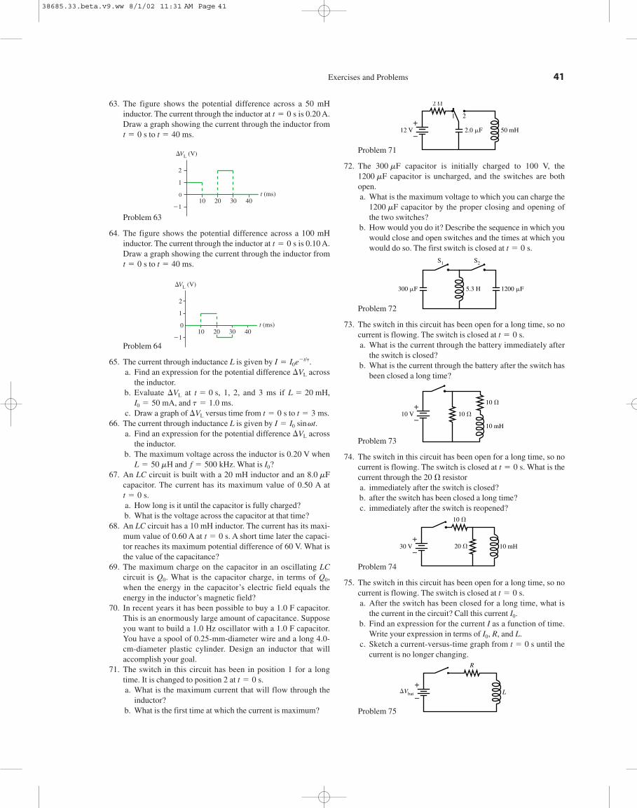
63. The figure shows the potential difference across a 50 mHinductor. The current through the inductor at is 0.20 A.Draw a graph showing the current through the inductor from
to
Problem 63
64. The figure shows the potential difference across a 100 mHinductor. The current through the inductor at is 0.10 A.Draw a graph showing the current through the inductor from
to
Problem 64
65. The current through inductance L is given by a. Find an expression for the potential difference across
the inductor.b. Evaluate at 1, 2, and 3 ms if
and c. Draw a graph of versus time from to
66. The current through inductance L is given by a. Find an expression for the potential difference across
the inductor.b. The maximum voltage across the inductor is 0.20 V when
and What is 67. An LC circuit is built with a 20 mH inductor and an
capacitor. The current has its maximum value of 0.50 A at
a. How long is it until the capacitor is fully charged?b. What is the voltage across the capacitor at that time?
68. An LC circuit has a 10 mH inductor. The current has its maxi-mum value of 0.60 A at A short time later the capaci-tor reaches its maximum potential difference of 60 V. What isthe value of the capacitance?
69. The maximum charge on the capacitor in an oscillating LCcircuit is What is the capacitor charge, in terms of when the energy in the capacitor’s electric field equals theenergy in the inductor’s magnetic field?
70. In recent years it has been possible to buy a 1.0 F capacitor.This is an enormously large amount of capacitance. Supposeyou want to build a 1.0 Hz oscillator with a 1.0 F capacitor.You have a spool of 0.25-mm-diameter wire and a long 4.0-cm-diameter plastic cylinder. Design an inductor that willaccomplish your goal.
71. The switch in this circuit has been in position 1 for a longtime. It is changed to position 2 at a. What is the maximum current that will flow through the
inductor?b. What is the first time at which the current is maximum?
t 5 0 s.
Q0 ,Q0 .
t 5 0 s.
t 5 0 s.
8.0 mFI0 ?f 5 500 kHz.L 5 50 mH
DVL
I 5 I0 sin vt.t 5 3 ms.t 5 0 sDVL
t 5 1.0 ms.I0 5 50 mA,L 5 20 mH,t 5 0 s,DVL
DVL
I 5 I0 e2t/t.
t (ms)0
DVL (V)
21
1
10
2
20 30 40
t 5 40 ms.t 5 0 s
t 5 0 s
10 20 30 40t (ms)0
DVL (V)
21
1
2
t 5 40 ms.t 5 0 s
t 5 0 s
Exercises and Problems 41
Problem 71
72. The capacitor is initially charged to 100 V, thecapacitor is uncharged, and the switches are both
open.a. What is the maximum voltage to which you can charge the
capacitor by the proper closing and opening ofthe two switches?
b. How would you do it? Describe the sequence in which youwould close and open switches and the times at which youwould do so. The first switch is closed at
Problem 72
73. The switch in this circuit has been open for a long time, so nocurrent is flowing. The switch is closed at a. What is the current through the battery immediately after
the switch is closed?b. What is the current through the battery after the switch has
been closed a long time?
Problem 73
74. The switch in this circuit has been open for a long time, so nocurrent is flowing. The switch is closed at What is thecurrent through the resistora. immediately after the switch is closed?b. after the switch has been closed a long time?c. immediately after the switch is reopened?
Problem 74
75. The switch in this circuit has been open for a long time, so nocurrent is flowing. The switch is closed at a. After the switch has been closed for a long time, what is
the current in the circuit? Call this current b. Find an expression for the current I as a function of time.
Write your expression in terms of R, and L.c. Sketch a current-versus-time graph from until the
current is no longer changing.
Problem 75
R
LDVbat�
�
t 5 0 sI0 ,
I0 .
t 5 0 s.
10 V
10 mH30 V�
�20 V
20 Vt 5 0 s.
10 V
10 mH
10 V�
�10 V
t 5 0 s.
300 �F 1200 �F
S2
5.3 H
S1
t 5 0 s.
1200 mF
1200 mF300 mF
1 2
2 V
2.0 �F 50 mH12 V�
�
38685.33.beta.v9.ww 8/1/02 11:31 AM Page 41

Challenge Problems
76. An L-shaped conductor moves at 10 m/s across a stationaryL-shaped conductor in a 0.10 T magnetic field. The two ver-tices overlap, so that the enclosed area is zero, at Theconductor has a resistance of 0.010 ohms per meter.a. In which direction does the induced current flow?b. Find expressions for the induced emf and the induced cur-
rent as functions of time.c. Evaluate and I at
Problem 76
77. A metal wire of length moves with speed v parallel to astraight wire that is carrying current I. The distance betweenthe two wires is d. Find an expression for the potential differ-ence between the two ends of the moving wire.
Problem 77
78. A closed, square loop is formed with 40 cm of wire havingas shown in the figure. A 0.50 T magnetic field is
perpendicular to the loop. At two diagonally oppositecorners of the loop begin to move apart at 0.293 m/s.a. How long does it take the loop to collapse to a straight
line?b. Find an expression for the induced current I as a function
of time while the loop is collapsing. Assume that the sidesremain straight lines during the collapse.
c. Evaluate I at four or five times during the collapse, thendraw a graph of I versus t.
Problem 78
0.293 m/s0.293 m/s
t 5 0 s,R 5 0.10 V,
I
d
v
�
/
Stationary
B 5 0.1 T
10 m/s
t 5 0.10 s.E
t 5 0 s.
42 C H A P T E R 33 . Electromagnetic Induction
79. Let’s look at the details of eddy-current braking. A squareloop, length on each side, is shot with velocity into a uni-form magnetic field B. The field is perpendicular to the planeof the loop. The loop has mass m and resistance R, and itenters the field at Assume that the loop is moving to theright along the x-axis and that the field begins at a. Find an expression for the loop’s velocity as a function of
time as it enters the magnetic field. You can ignore gravity,and you can assume that the back edge of the loop has notentered the field.
b. Calculate and draw a graph of v over the intervalfor the case that
and The backedge of the loop does not reach the field during this timeinterval.
80. An square loop is halfway into a magneticfield that is perpendicular to the plane of the loop. The loop’smass is 10 g and its resistance is A switch is closed at
causing the magnetic field to increase from 0 to 1.0 Tin 0.010 s.a. What is the induced current in the square loop?b. What is the force on the loop when the magnetic field is
0.50 T? Is the force directed into the magnetic field oraway from the magnetic field?
c. What is the loop’s acceleration at when thefield strength is 0.50 T? If this acceleration stayed con-stant, how far would the loop move in 0.010 s?
d. Because 0.50 T is the average field strength, your answerto c is an estimate of how far the loop moves during the0.010 s in which the field increases to 1.0 T. If your answeris then it is reasonable to neglect the movementof the loop during the 0.010 s that the field ramps up. Isneglecting the movement reasonable?
e. With what speed is the loop “kicked” away from the mag-netic field?
Hint: What is the impulse on the loop?81. High-frequency signals are often transmitted along a coaxial
cable, such as the one shown in the figure. For example, thecable TV hookup coming into your home is a coaxial cable.The signal is carried on a wire of radius while the outer con-ductor of radius is grounded. A soft, flexible insulatingmaterial fills the space between them, and an insulating plas-tic coating goes around the outside.a. Find an expression for the inductance per meter of a coax-
ial cable. To do so, consider the flux through a rectangle oflength that spans the gap between the inner and outerconductor.
b. Evaluate the inductance per meter of a cable havingand
Problem 81r
2
Inner conductorRadius r
1
Outer conductor
r2 5 3.0 mm.r1 5 0.50 mm
/
r2
r1
V 8 cm,
t 5 0.005 s,
t 5 0 s,0.010 V.
8.0 cm 3 8.0 cm
B 5 0.10 T.R 5 0.0010 V,m 5 1.0 g,/ 5 10 cm,v0 5 10 m/s,0 s # t # 0.04 s
x 5 0.t 5 0.
v0/
38685.33.beta.v9.ww 8/1/02 11:31 AM Page 42

Stop To Think Answers 43
Stop To Think Answers
Stop To Think 33.1: e. According to the right-hand rule, the mag-netic force on a positive charge carrier is to the right.
Stop To Think 33.2: No. The charge carriers in the wire move par-allel to There’s no magnetic force on a charge moving parallel toa magnetic field.
Stop To Think 33.3: is zerobecause there’s no field. is also zero because there’s no cur-rent flow around the loop. The charge carriers in both the rightand left edges are pushed to the bottom of the loop, creating amotional emf but no current flow. The currents at 2 and 4 flow inopposite directions, but the forces on the segments in the fieldare both to the left and of equal magnitude.
Stop To Think 33.4: Clockwise. The wire’s magnetic field as itpasses through the loop is into the page. The flux through the loop
Fr
3
Fr
10 Fr2 0 5 0 Fr4 0 . 0 Fr1 0 5 0 Fr3 0 .Br
.
decreases into the page as the wire moves away. To oppose thisdecrease, the induced magnetic field needs to point into the page.
Stop To Think 33.5: d. The flux is increasing into the loop. Tooppose this increase, the induced magnetic field needs to point outof the page. This requires a counterclockwise induced current.Using the right-hand rule, the magnetic force on the current in theleft edge of the loop is to the right, away from the field. The mag-netic forces on the top and bottom segments of the loop are inopposite directions and cancel each other.
Stop To Think 33.6: b or f. The potential decreases in the directionof increasing current and increases in the direction of decreasingcurrent.
Stop To Think 33.7: so smaller total resis-tance gives a larger time constant. The parallel resistors have totalresistance R/2. The series resistors have total resistance 2R.
t 5 L/R,t3 . t1 . t2 .
38685.33.beta.v9.ww 8/1/02 11:31 AM Page 43
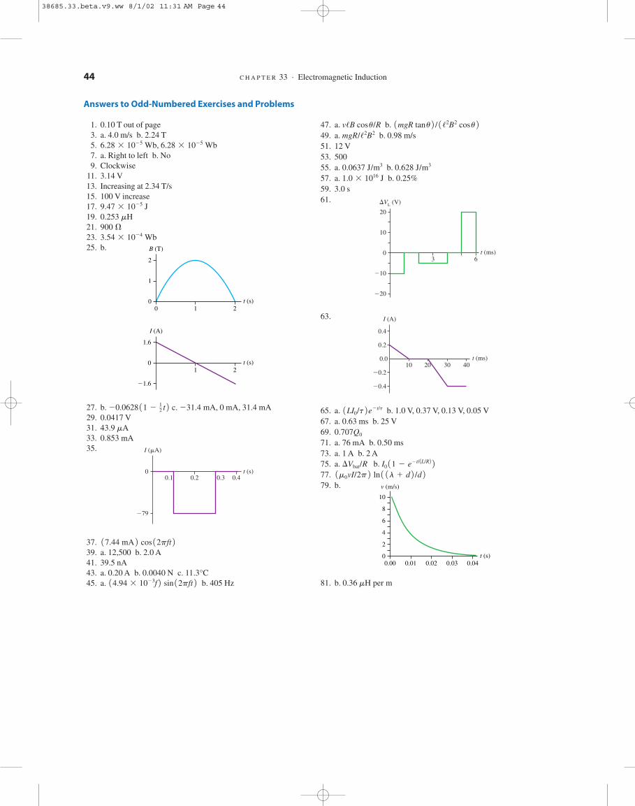
Answers to Odd-Numbered Exercises and Problems
1. 0.10 T out of page3. a. 4.0 m/s b. 2.24 T5.7. a. Right to left b. No9. Clockwise
11. 3.14 V13. Increasing at 2.34 T/s15. 100 V increase17.19.21.23.25. b.
27. b. c. 0 mA, 31.4 mA29. 0.0417 V31.33. 0.853 mA35.
37.39. a. 12,500 b. 2.0 A41. 39.5 nA43. a. 0.20 A b. 0.0040 N c. 11.3°C45. a. b. 405 Hz14.94 3 1023f 2 sin 12pft 2
17.44 mA 2 cos 12pft 2
t (s)0.1 0.2 0.3 0.4
0
I (�A)
279
43.9 mA
231.4 mA,20.0628 11 212 t 2
0
1
2
t (s)210
B (T)
t (s)21
0
1.6
21.6
I (A)
3.54 3 1024 Wb900 V0.253 mH9.47 3 1025 J
6.28 3 1025 Wb6.28 3 1025 Wb,
44 C H A P T E R 33 . Electromagnetic Induction
47. a. b. 49. a. b. 0.98 m/s51. 12 V53. 50055. a. b. 57. a. b. 0.25%59. 3.0 s61.
63.
65. a. b. 1.0 V, 0.37 V, 0.13 V, 0.05 V67. a. 0.63 ms b. 25 V69.71. a. 76 mA b. 0.50 ms73. a. 1 A b. 2 A75. a. b. 77.79. b.
81. b. 0.36 mH per m
0
2
4
6
8
10
t (s)0.01 0.02 0.03 0.040.00
v (m/s)
1m0 vI/2p 2 ln 1 1l 1 d 2 /d 2I0 11 2 e2t/1L/R2 2DVbat/R
0.707Q0
1LI0/t 2 e2t/t
t (ms)10 20 30 40
0.0
I (A)
0.2
20.2
20.4
0.4
t (ms)3 6
0
DVL (V)
210
10
20
220
1.0 3 1016 J0.628 J/m30.0637 J/m3
mgR//2B2
1mgR tan u 2 / 1 /2B2 cos u 2v/B cos u/R
38685.33.beta.v9.ww 8/1/02 11:31 AM Page 44

The Student WorkbookThe student workbook that will accompany the textbook bridges the gapbetween the textbook and end-of-chapter homework problems by providing stu-dents with an environment in which to learn and practice skills separately, muchas a musician practices technique separately from performance pieces.
The workbook exercises are linked to each section in the textbook chaptersand focus on developing specific skills (interpreting graphs, drawing free-bodydiagrams, etc.) The exercises are generally graphical, conceptual, or qualitative innature.
Included in this booklet are the workbook sections linked to Chapter 33.
WB_Knight.RM.33.pgs 8/1/02 11:41 AM Page 2

1
ElectromagneticInduction33
33.1 Induced Currents
33.2 Motional EMF
1. The figures below show one or more metal wires sliding on fixed metal rails in a magnetic field.For each, determine if the induced current flows clockwise, flows counterclockwise, or is zero.a. b. c.
B = 0
d. e. f.
2. A loop of copper wire is being pulled from between twomagnetic poles.a. Show on the figure the current flow induced in the loop.
Explain your reasoning.
b. Does either side of the loop experience a magnetic force? If so, draw a vector arrow orarrows on the figure to show any forces.
c. Label the magnetic poles of the induced current in the loop. Do this on the figure.d. Are the magnetic poles you labeled in part c attracted to or repelled by the permanent magnet?
S
NPull
WB_Knight.RM.33.pgs 8/1/02 11:41 AM Page 1

2 C H A P T E R 33 . Electromagnetic Induction
e. Is your answer to part d consistent with your force vectors in part b?
3. You want to insert a loop of copper wire between twopermanent magnets. Is there an attractive magnetic force thattends to pull the loop in, like a magnet pulls on a paper clip? Ordo you need to push the loop in against a repulsive force? Givea step by step analysis to support your answer.
4. A vertical, rectangular loop of copper wire is half in and half outof a horizontal magnetic field. (The field is zero beneath thedotted line.) The loop is released and starts to fall.a. Add arrows to the figure to show the direction of the induced
current in the loop.b. Is there a net magnetic force on the loop? If so, in which
direction? Explain.
S
NPush
Up
Down
B
B
B = 0
WB_Knight.RM.33.pgs 8/1/02 11:41 AM Page 2

6. The figure shows an edge view of a coppersheet being pulled between two magneticpoles.a. Add a dot or an X to each of the
circles to indicate the direction inwhich eddy currents are flowing inand out of the page.
b. Label the magnetic poles of any induced current loops.c. Do the magnetic poles you labeled in part b experience magnetic forces? If so, add force
vectors to the figure to show the directions. If not, why not?
d. Is there a net magnetic force on the copper sheet? If so, in which direction?
5. Two very thin sheets of copper are pulled through a magnetic field. Do eddy currents flow inthe sheet? If so, show them on the figures, with arrows to indicate the direction of flow. If not,why not?a. b.
Student Workbook 3
S
NPull
WB_Knight.RM.33.pgs 8/1/02 11:41 AM Page 3

7. An insulating rod pushes the copper loop backand forth. The left edge of the loop, which isalways in the magnetic field, oscillatesbetween and as shown in thetop graph. The right edge of the loop, whichincludes a lightbulb, is always outside themagnetic field.
a. Draw the velocity graph for the loop. Makesure it aligns with the position graph above it.
b. Draw a graph of the induced current in theloop as a function of time. Let a clockwisecurrent be a positive number and acounterclockwise graph be a negativecurrent.
c. Draw a graph of the brightness of thelightbulb as a function of time.
Note: There are no numbers on the verticalscale. The shape of each graph is the importantresult.
x 5 1L,x 5 2L
4 C H A P T E R 33 . Electromagnetic Induction
Insulator
–L 0 Lx
Edge offield
x left edge
L
0
–L
t
0
v loop
t
0
I loop
t
0 t
Brightness
WB_Knight.RM.33.pgs 8/1/02 11:41 AM Page 4

Student Workbook 5
33.3 Magnetic Flux
8. The figure shows five different loops in a magnetic field. The numbers indicate the lengths ofthe sides and the strength of the field. Rank in order the magnetic fluxes from thelargest flux to the smallest. Some may be equal. Give your answer in the formA . B 5 C . D.
F5 ,F1 , c,
Ranking:
Explanation:
9. The figure shows four different circular loops that are perpendicular to the page. The radius ofloops 3 and 4 is twice that of loops 1 and 2. The magnetic field is the same for each. Rankorder the magnetic fluxes from the largest flux to the smallest. Some may beequal. Give your answer in the form A . B 5 C . D.
F4 ,F1 , c,
Ranking:
Explanation:
2
2B = 1
Loop 1
1
1
Loop 2
B = 21
2
B = 1
Loop 3
2
1
B = 2
Loop 4
2
1
B = 0
B = 2
Loop 5
45°Loop 2r = 1
Loop 3r = 2
45°
Loop 1r = 1
Loop 4r = 2
B
B
WB_Knight.RM.33.pgs 8/1/02 11:41 AM Page 5

6 C H A P T E R 33 . Electromagnetic Induction
10. A circular loop rotates at constant speed about an axle throughthe center of the loop. The figure shows an edge view and definesthe angle which increases from to as the loop rotates.
a. At what angle or angles is the magnetic flux a maximum?_______
b. At what angle or angles is the magnetic flux a minimum?_______
c. At what angle or angles is the magnetic flux changing mostrapidly? Explain your choice.
11. A magnetic field is perpendicular to a loop. The graph shows how the magnetic field changesas a function of time, with positive values for B indicating a field into the page and negativevalues a field out of the page. Several points on the graph are labeled.
360°0°f,
f
Axle
B
t
2 T
–2 T
0 T
B
a
b
c
d
e
Field through loop
a. At which point or points is the flux through the loop a maximum?
b. At which point or points is the flux through the loop a minimum?
c. At which point or points is the flux changing most rapidly?
d. At which point or points is the flux changing least rapidly?
WB_Knight.RM.33.pgs 8/1/02 11:41 AM Page 6

Student Workbook 7
33.4 Lenz’s Law
33.5 Faraday’s Law
12. Does the loop of wire have a clockwise current, a counterclockwise current,or no current under the following circumstances? Explain your reasoning.a. The magnetic field points out of the page and its strength is increasing.
b. The magnetic field points out of the page and its strength is constant.
c. The magnetic field points out of the page and its strength is decreasing.
13. Two loops of wire are stacked vertically, one above the other. Doesthe upper loop have a clockwise current, a counterclockwise current,or no current at the following times? Explain your reasoning.a. Before the switch is closed.
b. Immediately after the switch is closed.
c. Long after the switch is closed.
d. Immediately after the switch is reopened.
WB_Knight.RM.33.pgs 8/1/02 11:41 AM Page 7

8 C H A P T E R 33 . Electromagnetic Induction
14. A loop of wire is perpendicular to a magneticfield. The magnetic field strength as a functionof time is given by the top graph. Draw a graphof the current in the loop as a function of time.Let a positive current represent a current thatcomes out of the top of the loop and enters thebottom of the loop. There are no numbers forthe vertical axis, but your graph should have thecorrect shape and proportions.
B
0 1 2 3 4t (s)
B
1 2 3 40t (s)
I loop
15. A loop of wire is horizontal. A bar magnet is pushed toward theloop from below, along the axis of the loop.a. In what direction does current flow in the loop? Explain.
b. Is there a magnetic force on the loop? If so, in whichdirection? Explain.Hint: A current loop is a magnetic dipole.
c. Is there a force on the magnet? If so, in which direction?
16. A bar magnet is pushed toward a loop of wire, as shown. Isthere a current flow in the loop? If so, in which direction? If not,why not?
S
N
S N
WB_Knight.RM.33.pgs 8/1/02 11:41 AM Page 8
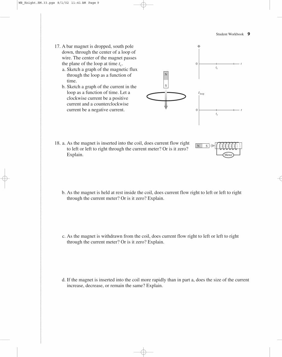
Student Workbook 9
17. A bar magnet is dropped, south poledown, through the center of a loop ofwire. The center of the magnet passesthe plane of the loop at time a. Sketch a graph of the magnetic flux
through the loop as a function oftime.
b. Sketch a graph of the current in theloop as a function of time. Let aclockwise current be a positivecurrent and a counterclockwisecurrent be a negative current.
tc .
S
N
0tc
t
F
0tc
t
I loop
18. a. As the magnet is inserted into the coil, does current flow rightto left or left to right through the current meter? Or is it zero?Explain.
b. As the magnet is held at rest inside the coil, does current flow right to left or left to rightthrough the current meter? Or is it zero? Explain.
c. As the magnet is withdrawn from the coil, does current flow right to left or left to rightthrough the current meter? Or is it zero? Explain.
d. If the magnet is inserted into the coil more rapidly than in part a, does the size of the currentincrease, decrease, or remain the same? Explain.
N S
Meter
WB_Knight.RM.33.pgs 8/1/02 11:41 AM Page 9

10 C H A P T E R 33 . Electromagnetic Induction
19. a. Just after the switch on the left coil isclosed, does current flow right to left orleft to right through the current meter ofthe right coil? Or is it zero? Explain.
b. Long after the switch on the left coil is closed, does current flow right to left or left to rightthrough the current meter of the right coil? Or is it zero? Explain.
c. Just after the switch on the left coil is reopened, does current flow right to left or left to rightthrough the current meter of the right coil? Or is it zero? Explain.
20. A solenoid is perpendicular to the page, and itsfield strength is increasing. Three circular wireloops of equal radii are shown. Rank order the sizeof the induced emf in the three rings, from thelargest to the smallest.
Ranking:
Explanation:
SolenoidB increasing
Loop 1
Loop 2
Loop 3
Meter
WB_Knight.RM.33.pgs 8/1/02 11:41 AM Page 10

21. A conducting loop around a magnetic field contains twolightbulbs, as shown. The wires connecting the bulbs are ideal,with no resistance. The magnetic field is increasing rapidly.a. Do the bulbs glow? Why or why not?
b. If they glow, which bulb is brighter? Or are they equally bright? Explain.
22. A conducting loop around a magnetic field contains threelightbulbs, as shown. The wires connecting the bulbs are ideal,with no resistance. The magnetic field is increasing rapidly.Rank order the brightness of the three bulbs, from brightest toleast bright.
Student Workbook 11
A B
A
C
B
WB_Knight.RM.33.pgs 8/1/02 11:41 AM Page 11

23. A metal wire is resting on a U-shaped conducting rail. The rail is fixed in position, but wire is free move.a. If the magnetic field is increasing in strength, does the wire:
i. Remain in place. vi. Move out of the plane of the page,ii. Move to the right. breaking contact with the rail.
iii. Move to the left. vii. Rotate clockwise.iv. Move up on the page. viii. Rotate counterclockwise.v. Move down on the page. ix. Some combination of these? If so, which?
Explain your choice.
b. If the magnetic field is decreasing in strength, which of the above happens?
33.6 Induced Field and Electromagnetic Waves
33.7 Induced Current: Three Applications
No exercises.
12 C H A P T E R 33 . Electromagnetic Induction
Fixed rail Wire
WB_Knight.RM.33.pgs 8/1/02 11:41 AM Page 12

Student Workbook 13
33.8 Inductors
24. The figure shows the current through an inductor. Apositive current is defined as a current going from top tobottom. At the time corresponding to each of the labeledpoints, does the potential across the inductor (going fromtop to bottom) increase, decrease, or stay the same?
a. __________________ e. __________________
b. __________________ f. __________________
c. __________________ g.__________________
d. __________________
25. a. Can you tell which of these inductors has the largest currentflowing through it? If so, which one? If not, why not?
b. Can you tell through which inductor the current is changing most rapidly? If so, which one?If not, why not?
c. If the current enters the inductor from the bottom, can you tell if the current is increasing,decreasing, or staying the same? If so, which one and what is your reasoning? If not, why not?
26. Rank order, from most positive to most negative, theinductor’s potential difference
at the six labeled points. is the change ingoing from the top of the inductor to the bottom. Somemay be equal. Note that
Ranking:
Explanation:
0 V . 22 V.
DVL1DVL 2 f
1DVL 2 b , c,1DVL 2 a ,
t
a b c
d
e f g
I
I
2 H 2 V
+
–I1
1 H 4 V
+
–I2
t
a
bc
d
e
fI
I
WB_Knight.RM.33.pgs 8/1/02 11:41 AM Page 13

14 C H A P T E R 33 . Electromagnetic Induction
33.9 LC Circuits
27. An LC circuit oscillates at a frequency of 2000 Hz. What will the frequency be if theinductance is quadrupled?
28. The capacitor in an LC circuit has maximum charge at The current through theinductor next reaches a maximum at a. When will the inductor current be a maximum in the opposite direction?
b. What is the circuit’s period of oscillation?
29. Three LC circuits are made with the same capacitor but differentinductors. The figure shows the inductor current as a function oftime. Rank order the three inductances and fromlargest to smallest. Some may be equal. Give your answer in theform
Ranking:
Explanation:
A . B 5 C . D.
L3L2 ,L1 ,
t 5 3 ms.t 5 1 ms.
t
I1 3
2
WB_Knight.RM.33.pgs 8/1/02 11:41 AM Page 14

Student Workbook 15
33.10 LR Circuits
30. Rank in order, from largest to smallest, the three time constants and for these threecircuits.
t3t2 ,t1 ,
Ranking:
Explanation:
31. Three LR circuits are made with the same resistor but differentinductors. The figure shows the inductor current as a function oftime. Rank order the three inductances and fromlargest to smallest.
Ranking:
Explanation:
32. a. What is the battery current immediately after the switchcloses? Explain.
b. What is the battery current after the switch has been closed along time? Explain.
L3L2 ,L1 ,
R
LCircuit 1
R
LCircuit 2
R
R
L
Circuit 3
R
t
I
1
2
3
10 V
5 �
5 mH
WB_Knight.RM.33.pgs 8/1/02 11:41 AM Page 15

Notes
WB_Knight.RM.33.pgs 8/1/02 11:41 AM Page 68