Embed Size (px)
Citation preview

GLASS DRILL INSTRUCTION MANUALINSTALLATION INSTRUCTIONScrlaurence.com
C.R. Laurence Co., Inc. • 2503 E. Vernon Ave., Los Angeles, CA 90058 • 1.800.421.6144 • crlaurence.com
APRIL 2021
KLARITY INTERIOR PARTITION SYSTEM
NOTE: Shown with optional CRL375 Sliding Door hardware.

C.R. Laurence Co., Inc. • 2503 E. Vernon Ave., Los Angeles, CA 90058 • 1.800.421.6144 • crlaurence.com
KLARITY INTERIOR PARTITION SYSTEM
P. 2
TABLE OF CONTENTSSYSTEM LIMITATIONS . . . . . . . . . . . . . . . . . . . . . . . . . . . . . . . . . . . . . . . . . . . . . . . . . . . . . . . . . . . . . . . . . . . . . . . . . . . . . 2GLASS FABRICATION . . . . . . . . . . . . . . . . . . . . . . . . . . . . . . . . . . . . . . . . . . . . . . . . . . . . . . . . . . . . . . . . . . . . . . . . . . . . . 2PARTS LIST . . . . . . . . . . . . . . . . . . . . . . . . . . . . . . . . . . . . . . . . . . . . . . . . . . . . . . . . . . . . . . . . . . . . . . . . . . . . . . . . . . . . . . . 3
Glass Clamps . . . . . . . . . . . . . . . . . . . . . . . . . . . . . . . . . . . . . . . . . . . . . . . . . . . . . . . . . . . . . . . . . . . . . . . . . . . . . . . . . . 3Flange Covers . . . . . . . . . . . . . . . . . . . . . . . . . . . . . . . . . . . . . . . . . . . . . . . . . . . . . . . . . . . . . . . . . . . . . . . . . . . . . . . . . 3Bottom Rail Parts . . . . . . . . . . . . . . . . . . . . . . . . . . . . . . . . . . . . . . . . . . . . . . . . . . . . . . . . . . . . . . . . . . . . . . . . . . . . . . 3Klarity 7’ Posts . . . . . . . . . . . . . . . . . . . . . . . . . . . . . . . . . . . . . . . . . . . . . . . . . . . . . . . . . . . . . . . . . . . . . . . . . . . . . . . . . 3Klarity 6’ Posts . . . . . . . . . . . . . . . . . . . . . . . . . . . . . . . . . . . . . . . . . . . . . . . . . . . . . . . . . . . . . . . . . . . . . . . . . . . . . . . . . 3Klarity 5’ Posts . . . . . . . . . . . . . . . . . . . . . . . . . . . . . . . . . . . . . . . . . . . . . . . . . . . . . . . . . . . . . . . . . . . . . . . . . . . . . . . . . 3
TYPICAL CONFIGURATIONS . . . . . . . . . . . . . . . . . . . . . . . . . . . . . . . . . . . . . . . . . . . . . . . . . . . . . . . . . . . . . . . . . . . . . . 4OPTIONAL CONFIGURATIONS . . . . . . . . . . . . . . . . . . . . . . . . . . . . . . . . . . . . . . . . . . . . . . . . . . . . . . . . . . . . . . . . . . . . 4POST MOUNTING OPTIONS . . . . . . . . . . . . . . . . . . . . . . . . . . . . . . . . . . . . . . . . . . . . . . . . . . . . . . . . . . . . . . . . . . . . . . . 5POST INSTALLATION . . . . . . . . . . . . . . . . . . . . . . . . . . . . . . . . . . . . . . . . . . . . . . . . . . . . . . . . . . . . . . . . . . . . . . . . . . . . . . 5BOTTOM RAIL INSTALLATION . . . . . . . . . . . . . . . . . . . . . . . . . . . . . . . . . . . . . . . . . . . . . . . . . . . . . . . . . . . . . . . . . . . . . 6FLANGE COVER INSTALLATION . . . . . . . . . . . . . . . . . . . . . . . . . . . . . . . . . . . . . . . . . . . . . . . . . . . . . . . . . . . . . . . . . . 6GLASS CLAMP INSTALLATION . . . . . . . . . . . . . . . . . . . . . . . . . . . . . . . . . . . . . . . . . . . . . . . . . . . . . . . . . . . . . . . . . . . . 7GLASS INSTALLATION . . . . . . . . . . . . . . . . . . . . . . . . . . . . . . . . . . . . . . . . . . . . . . . . . . . . . . . . . . . . . . . . . . . . . . . . . . . . 8
IMPORTANT: READ THIS MANUAL THOROUGHLY BEFORE BEGINNING INSTALLATION
SYSTEM LIMITATIONSDesigned for Interior Applications. Not for use in guardrail applications where there is a difference of 30 inches or greater between two upper and lower floor surfaces.Maximum Spacing Between Posts: 54” (1372 mm)
GLASS FABRICATIONFixed Lite and Sidelite Glass1/2” (12 mm) thick fully tempered glass with exposed edges polished.9/16” (14 mm) thick laminated glass.Panel Height = Overall Height minus 2” (51 mm)Maximum Height: 12” (305 mm) above top of post. Panel Width = post to post centerline minus 3/4” (19 mm)Maximum Width: 60” (1524 mm) Sliding Door Glass3/8” (10 mm) thick fully tempered glass with exposed edges polished.Maximum Height: 84” (2134 mm)Maximum Width: 40” (1016 mm)NOTE: See Installation Instructions for CRL375 Sliding System for additional information.
Swinging Door Glass1/2” (12 mm) thick fully tempered glass with exposed edges polished.Maximum Height: 84” (2134 mm)Maximum Width: 36” (914 mm)NOTE: See Installation Instructions for FH4BSS Floating Header and PH20C for additional information.
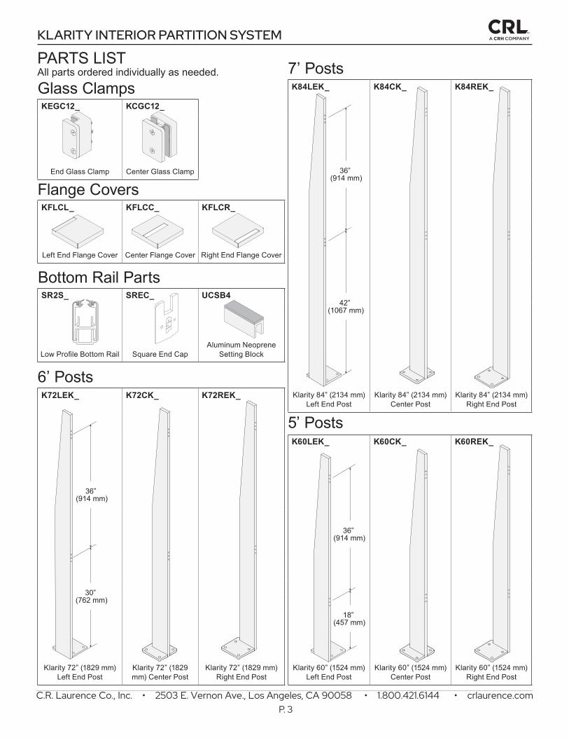
7’ PostsGlass Clamps K84LEK_ K84CK_ K84REK_
KEGC12_ KCGC12_
End Glass Clamp Center Glass Clamp
Flange CoversKFLCL_ KFLCC_ KFLCR_
Left End Flange Cover Center Flange Cover Right End Flange Cover
Bottom Rail PartsSR2S_ SREC_ UCSB4
Low Profile Bottom Rail Square End CapAluminum Neoprene
Setting Block
6’ PostsK72LEK_ K72CK_ K72REK_ Klarity 84” (2134 mm)
Left End PostKlarity 84” (2134 mm)
Center PostKlarity 84” (2134 mm)
Right End Post
5’ PostsK60LEK_ K60CK_ K60REK_
Klarity 72” (1829 mm)Left End Post
Klarity 72” (1829 mm) Center Post
Klarity 72” (1829 mm)Right End Post
Klarity 60” (1524 mm)Left End Post
Klarity 60” (1524 mm)Center Post
Klarity 60” (1524 mm)Right End Post
36” (914 mm)
42” (1067 mm)
36” (914 mm)
18” (457 mm)
36” (914 mm)
30” (762 mm)
C.R. Laurence Co., Inc. • 2503 E. Vernon Ave., Los Angeles, CA 90058 • 1.800.421.6144 • crlaurence.com
KLARITY INTERIOR PARTITION SYSTEM
P. 3
PARTS LISTAll parts ordered individually as needed.

GlassFixed LiteInstallation
B
A
C
54” (1372 mm) maximum
3/4” (19 mm) Glass Gap
Fixed LitesFixed Lite
SR2S
12” (305 mm)
12” (305 mm)
Sliding Door with SidelitesUsing CRL375 Sliding System (Sold Separately)
Swing Door with SidelitesUsing CRL FH4BSS Floating Header and Door Hardware (Sold Separately)
Sidelite GlassSliding DoorInstallation
2-7/8” (73 mm)
7/8” (22 mm)
Countersunk Holes for Header
12” (305 mm)
B
A
C
Sidelite GlassSwinging Door
Installation
12” (305 mm)
2-7/8” (73 mm)
7/8” (22 mm)
B
A
C
Countersunk Holes for Header
SR2S
CRL375
Door and Sidelite
84” (
2134
mm
) max
imum
Doo
r Gla
ss H
eigh
t
SR2S
Sidelite
DR2S
PH20C
FH4Door
84” (
2134
mm
) max
imum
Doo
r Gla
ss H
eigh
t
A = 36” (914 mm)B = 16”, 28” or 42” (406, 711 or 1016 mm) based on post selection. See Page 2.C = Maximum 12” (305 mm) above top of post.
A = 36” (914 mm)B = 16”, 28” or 42” (406, 711 or 1016 mm) based on post selection. See Page 2.C = Maximum 12” (305 mm) above top of post.
A = 36” (914 mm)B = 16”, 28” or 42” (406, 711 or 1016 mm) based on post selection. See Page 2.C = Maximum 12” (305 mm) above top of post.
C.R. Laurence Co., Inc. • 2503 E. Vernon Ave., Los Angeles, CA 90058 • 1.800.421.6144 • crlaurence.com
KLARITY INTERIOR PARTITION SYSTEM
P. 4
TYPICAL CONFIGURATIONS
OPTIONAL CONFIGURATIONS

Use String Line or Laser to ensure Posts are
in a straight line.
RightEnd Post
LeftEnd Post
CenterPost
Maximum 54” (1372 mm)
between Posts
Ensure Posts areLevel and Plumb.
2
1
1
EXTERIOR
Install Center Posts.
Install End Posts.
NOTE: Install Posts using fasteners specified for your conditions. Lag Bolts for wood shown.
21
OROR
(4) EBA334 3/8" x 3-7/8" Concrete Anchors per Plate
CONCRETE WOOD
(4) LB600 Lag Bolts per Plate
(4) SHCS12x34 Cap Screws per Plate
STEEL
Fastener type suitable for substrate.
C.R. Laurence Co., Inc. • 2503 E. Vernon Ave., Los Angeles, CA 90058 • 1.800.421.6144 • crlaurence.com
KLARITY INTERIOR PARTITION SYSTEM
P. 5
POST INSTALLATION
POST MOUNTING OPTIONS

Install Bottom Sidelite Rail.
2
1
1
NOTE: Position Center of Sidelite Rail 1-1/16” from edge of Posts.
1-1/16” (27 mm)
Post
Sidelite Rail
Reversible Saddle
Fastener suitablefor substrate
GlassClamp
EXTERIOR
SideliteRail
1-1/16”(27 mm)
B2
C2
A2
Right EndPost
Right EndFlange Cover
Left EndFlange Cover
CenterFlange Cover
Left EndPost
CenterPost
Fastener type and spacingsuitable for substrate.
Fastener type and spacingsuitable for substrate.
1 A
B1
B1
Slide Flange Cover over top of post down to base.
C.R. Laurence Co., Inc. • 2503 E. Vernon Ave., Los Angeles, CA 90058 • 1.800.421.6144 • crlaurence.com
KLARITY INTERIOR PARTITION SYSTEM
P. 6
BOTTOM RAIL INSTALLATION
FLANGE COVER INSTALLATION

24231
THREADLOCKER
242
24231
THREADLOCKER242
24231
THREADLOCKER242
24231
THREADLOCKER
242
24231
THREADLOCKER
242
24231
THREADLOCKER
242
EXTERIOR
SideliteRail
A2
B2
B2
C2
C2
A2
Center GlassClamp
End GlassClamp
End GlassClamp
Right EndPost
Left EndPost
CenterPost
Install Glass Clamps on Posts.
Unpack and remove Clamping Plates from Glass Clamps.
2
1
* NOTE: Loctite ® (CRL Cat. No. 24231)
is recommended on all screw threadsduring final assembly.
24231
THREADLOCKER242 B2
Center Post
CenterGlass Clamp
24231
THREADLOCKER242
C2
Left End Post
EndGlass Clamp
24231
THREADLOCKER242 A2
Right End Post
EndGlass Clamp
NOTE: Orient End Glass Clamps with glass pocket facing glass when attaching to posts.
1 A
KEGC12_End Glass Clamp
KCGC12_Center Glass Clamp
B1
C.R. Laurence Co., Inc. • 2503 E. Vernon Ave., Los Angeles, CA 90058 • 1.800.421.6144 • crlaurence.com
KLARITY INTERIOR PARTITION SYSTEM
P. 7
GLASS CLAMP INSTALLATION

2
EXTERIOR
3 B
3 B
3 C
3 C
Right EndPost
Left EndPost
CenterPost
4
5
5
1
1
Place UCSB4 Setting Blocksat quarter points.
Place UCSB4 Setting Blocksat quarter points.
InstallGlazing Gaskets.
Install EndCaps.
InstallEnd Caps.
SideliteRail
A3
24231
THREADLOCKER
242
24231
THREADLOCKER
242
24231
THREADLOCKER
242
24231
THREADLOCKER
242
24231
THREADLOCKER
242
A3
24231
THREADLOCKER
242
Place Setting Blocks at quarter points of each panel.
3
4
2
1
Fit Glass Panels between Clamps and lower into Bottom Rail.
Roll Glazing Gaskets into Bottom Rail at interior and exterior.
Install End Caps at Bottom Rail.
* NOTE: Loctite ® (CRL Cat. No. 24231)
is recommended on all screw threadsduring final assembly.
24231
THREADLOCKER242
3 B
CenterPost
CenterClamping
Plate
24231
THREADLOCKER242
3 C
Left EndPost
EndClamping
Plate
24231
THREADLOCKER242
A3
Right EndPost
EndClamping
Plate
5
Install Clamping Plates to secure glass in position.
C.R. Laurence Co., Inc. • 2503 E. Vernon Ave., Los Angeles, CA 90058 • 1.800.421.6144 • crlaurence.com
KLARITY INTERIOR PARTITION SYSTEM
P. 8
GLASS INSTALLATION