Embed Size (px)
Citation preview

Seymenoba Elektrik Üretimi A.Ş.
Yeni Demiryolu Caddesi No: 62 41135
Kartepe-Kocaeli/TÜRKİYE
Phone: +90 (262) 317 1000
Fax : +90 (262) 317 1099
KIRIKKALE COGENERATION POWER
PLANT
SUPPLEMENTARY DOCUMENT FOR
INTERNATIONAL ESIA STUDY
DOKAY-ÇED Çevre Mühendisliği Ltd. Şti.
Ata Mah. Kabil Cad. No: 140/A Dikmen
06460 Çankaya-ANKARA/TÜRKİYE
Phone: +90 (312) 475 7131
Fax: +90 (312) 475 7130
APRIL 2013
ANKARA

KIRIKKALE COGENERATION POWER PLANT
Project No.: 169.02.02
SUPPLEMENTARY DOCUMENT FOR INTERNATIONAL ESIA STUDY
April / 2013
REVISION LOG
Revizyon Numarası
Revision Number
0 1 2
Tarih
Date 11.03.2013 04.04.2013 16.04.2013
Rapor Adı
Report Title
Supplementary Document for Kırıkkale Cogeneration Power Plant International ESIA Study
Hazırlayan
Prepared by Orçun YILDIZCA
Teknik Kontrol
Technical Control
Deniz YURTERİ
Kalite Kontrol
Quality Control
Yeşim AŞTI
Şirket Müdürü
Director
Prof. Dr. Coşkun YURTERİ
Form No: PJ-001/F02-R04

i i / 46
Supplementary Document for Kırıkkale Cogeneration Power Plant International ESIA Study April 2013
Project No: 169.02.02
i / 52
TABLE OF CONTENTS
Page
Table of Contents i
List of Tables iv
List of Figures iv
Abbreviations vi
1. INTRODUCTION ................................................................................................................... 1
2. PROJECT CATEGORIZATION ............................................................................................ 3
3. INFORMATION ON THE PROJECT OWNER AND CONTRACTOR ................................ 4
4. PROJECT DESCRIPTION .................................................................................................... 5
5. PROJECT ALTERNATIVES AND CONFIGURATION OPTIONS ...................................... 8
5.1 Turkey’s Energy Demand and Need for the Project ............................................. 8
5.1.1 No Action (Zero Option) ......................................................................... 10
5.1.2 Need for the Project ............................................................................... 10
5.2 Site Alternatives ................................................................................................ 11
5.2.1 Alternative 1 ........................................................................................... 11
5.2.2 Alternative 2 ........................................................................................... 12
5.2.3 Other Site Alternatives ........................................................................... 12
5.2.4 Selected Project Area ............................................................................ 13
5.3 Cooling Alternatives .......................................................................................... 13
5.3.1 Wet Cooling ........................................................................................... 13
5.3.2 Dry Cooling ............................................................................................ 14
5.3.3 Selected Cooling System ....................................................................... 15
5.4 Configuration Options ........................................................................................ 18
5.4.1 System Configuration Option Analysis ................................................... 18
5.4.2 Selected Plant Configuration .................................................................. 21
5.4.3 Option 4 (Enhancement of the Selected Configuration) ......................... 21
6. TECHNICAL SPECIFICATIONS ........................................................................................ 24
6.1 EQUIPMENT TECHNICAL ISSUES .................................................................. 24
6.1.1 Gas Turbines ......................................................................................... 24
ii ii / 46
Supplementary Document for Kırıkkale Cogeneration Power Plant International ESIA Study April 2013
Project No: 169.02.02
ii / 52
6.1.2 Heat Recovery Steam Generators (HRSGs) .......................................... 25
6.1.3 Bypass Stacks ....................................................................................... 26
6.1.4 Steam Turbines and Auxiliaries ............................................................. 26
6.1.5 Steam Boilers and Flue Gas Desulphurization (FGD) System ............... 27
6.2 Back-up Fuel ..................................................................................................... 29
6.3 Discharge Water Line ........................................................................................ 31
6.4 Transmission Lines ........................................................................................... 31
6.5 Natural Gas Supply Line .................................................................................... 32
7. EXISTING ENVIRONMENTAL CHARACTERISTICS OF THE PROJECT AREA .......... 33
7.1 Flora and Fauna ................................................................................................ 33
7.2 Geological, Hydrogeological and Hydrological Characteristics .......................... 33
7.3 Meteorological and Climatic Characteristics ...................................................... 36
7.4 Natural and Archaeological Heritage ................................................................. 36
7.5 Expropriation & Easement ................................................................................. 36
7.6 Landscaping ...................................................................................................... 37
7.7 Land Use ........................................................................................................... 37
7.8 Population Characteristics of the Region ........................................................... 37
7.9 Seismic Activity ................................................................................................. 37
7.10 Soil Characteristics of the Region ...................................................................... 38
8. ENVIRONMENTAL IMPACTS OF THE PROJECT AND MITIGATION MEASURES..... 39
8.1 Use of Natural Resources ................................................................................. 39
8.1.1 Land Use ............................................................................................... 39
8.1.2 Fuel Use ................................................................................................ 39
8.1.3 Water Use .............................................................................................. 39
8.2 Impacts and Mitigation Measures ...................................................................... 40
8.2.1 Wastewater ............................................................................................ 40
8.2.2 Flora/Fauna ........................................................................................... 41
8.2.3 Noise ..................................................................................................... 42
8.2.4 Solid Waste ........................................................................................... 42
8.2.5 Emission ................................................................................................ 43
8.2.6 Transmission line and Pipelines ............................................................. 44

iii iii / 46
Supplementary Document for Kırıkkale Cogeneration Power Plant International ESIA Study April 2013
Project No: 169.02.02
iii / 52
9. COMPLIANCE WITH BEST AVAILABLE TECHNIQUES (BAT) AND INDUSTRIAL
EMISSIONS DIRECTIVE ................................................................................................... 46
9.1 Emissions .......................................................................................................... 46
9.2 Water Contamination ......................................................................................... 48
10. ADVANTAGES ON THE CURRENT POWER PLANT OF TÜPRAŞ REFINERY ........... 50
11. OVERVIEW OF ENVIRONMENTAL AND SOCIAL MANAGEMENT SYSTEM .............. 53
11.1 Occupational Health, Safety, and Environmental Policies of the Project
Owner and the Contractor ................................................................................. 53
11.2 Social Policies of the Project Owner and the Contractor .................................... 57
11.2.1 Grievance Mechanism for Workers ...................................................... 57
11.2.2 Community Relations and Grievance Mechanism for the Project ......... 59
11.2.3 Health, Safety, and Environment (HSE) Management Plan ................. 62
11.2.4 Workers Accommodation and Transportation ...................................... 64
11.2.5 Human Resources Policies .................................................................. 65
12. REFERENCES .................................................................................................................... 67

iv iv / 46
Supplementary Document for Kırıkkale Cogeneration Power Plant International ESIA Study April 2013
Project No: 169.02.02
iv / 52
LIST OF TABLES
Table 1. Technical Specifications of Kırıkkale CPP ........................................................... 7
Table 2. Turkey Local Resources Potential as of 2009 ..................................................... 9
Table 3. Projection for Energy Requirement of Turkey (Base Demand- High Scenario) ...10
Table 4. Kırıkkale CPP Ambient Conditions .....................................................................18
Table 5. Gas Turbine Options for 2/2/1 Configuration ......................................................18
Table 6. Gas Turbine Options for 3/3/1 Configuration ......................................................19
Table 7. Modeling Results of Configuration Options ........................................................21
Table 8. Utilities Required in Case of HFO Usage ...........................................................22
Table 9. Expected Diesel Fuel Oil Composition ...............................................................30
Table 10. Expected Heavy Fuel Oil (HFO) Composition ..................................................31
Table 11. Features of Kapulukaya Dam ...........................................................................35
Table 12. Kırıkkale Meteorological Station Long Years Average Temperature Data ........36
Table 13. Distribution of Population in Kırıkkale by Counties ...........................................37
Table 14. Wastewater Discharge Limit Values for the Project ..........................................40
Table 15. Mass Flow Rates and Concentrations of Pollutants for Natural Gas Conditions
.................................................................................................................................44
Table 16. Mass Flow Rates and Concentrations of Pollutants for Diesel Oil Conditions ...44
Table 17. GT and HRSG Emission Guarantees* ..............................................................47
Table 18. Steam Boilers Emissions Guarantees* .............................................................48
Table 19. Guaranteed Wastewater Discharge Values ......................................................49
Table 20. Features of Power Plant Unit Common Flue ....................................................50
Table 21. Monitoring Results of Power Plant Unit Common Flue from current operations at
the Refinery ..............................................................................................................51
LIST OF FIGURES
Figure 1. Satellite Image of the Project Area and its Vicinity ............................................. 1
Figure 2. Typical Diagram of a Cogeneration Power Plant ................................................ 6
Figure 3. Typical Cooling Tower ......................................................................................14
Figure 4. Air-Cooled Condenser Diagram ........................................................................15
Figure 5. Water Balance Diagram of the Project ..............................................................17
Figure 6. GE 6FA Gas Turbine ........................................................................................24

v v / 46
Supplementary Document for Kırıkkale Cogeneration Power Plant International ESIA Study April 2013
Project No: 169.02.02
v / 52
Figure 7. Typical HRSG System ......................................................................................26
Figure 8. Geological Map Showing the Project Area and its Surrounding .........................34
Figure 9. Seismic Map of Kırıkkale ...................................................................................38
Figure 10. Kırıkkale CPP Construction Stage Health, Safety, and Environmental
Management System Document Structure ...............................................................54
Figure 11. Técnicas Reunidas Project HSE Organization Chart .......................................56
Figure 12. Técnicas Reunidas Site HSE Organization Chart ............................................56
Figure 13. AES-Entek Helpline ........................................................................................58
Figure 14. Seymenoba Complaint Form...........................................................................61
Figure 15. Seymenoba “Continual Improvement” Model of PLAN-DO-CHECK-ACT ........63

vi vi / 46
Supplementary Document for Kırıkkale Cogeneration Power Plant International ESIA Study April 2013
Project No: 169.02.02
vi / 52
ABBREVIATIONS
% Percentage
°C Degree Celsius
AES-Entek AES-Entek Elektrik Üretimi A.Ş.
CEMP Construction Environmental Management Plan
CPP Cogeneration Power Plant
DOKAY-ÇED DOKAY-ÇED Çevre Mühendisliği Ltd. Şti.
EBRD European Bank for Reconstruction and Development
EIA Environmental Impact Assessment
ESIA (International) Environmental and Social Impact Assessment
EU European Union
HSE Health, Safety, and Environment
HSE CTS HSE Compliance Tracking System
IFC International Finance Corporation
kV Kilovolt
kWh Kilowatt-hour
m Meter
m3 Cubic Meter
MWe Megawatt electrical
MWt Megawatt thermal
NTS Non-technical Summary
OPIC Overseas Private Investment Corporation
Pcs Pieces
PR Performance Requirement
PS Performance Standard
SEP Stakeholder Engagement Plan
Seymenoba Seymenoba Elektrik Üretimi A.Ş

1 / 67 1 / 46
Supplementary Document for Kırıkkale Cogeneration Power Plant International ESIA Study April 2013
Project No: 169.02.02
1 / 52
1. INTRODUCTION
Seymenoba Elektrik Üretimi A.Ş., (Seymenoba) a subsidiary of AES-Entek Elektrik
Üretimi A.Ş. (AES-Entek) plans to construct a Cogeneration Power Plant (CPP) having an
installed capacity of 233.7 MWe nearby the existing Tüpraş Refinery located in Kırıkkale.
Project Site is on the southwest of Kırıkkale province and about 10 km distant from the
city center of Kırıkkale on Kırıkkale-Kırşehir Road (see Figure 1).
Figure 1. Satellite Image of the Project Area and its Vicinity

2 / 67 2 / 46
Supplementary Document for Kırıkkale Cogeneration Power Plant International ESIA Study April 2013
Project No: 169.02.02
2 / 52
The plant will mainly serve to meet steam consumption and electricity demand of the
Tüpraş refinery which is 38 MWe. The surplus generation will be supplied to the national
mains through 154 kV transmission line.
The Project is included in the scope of the paragraph (a) (the thermal power plants and
other incineration systems having a total thermal power of 300 MWt) of the Article 2 of
Annex-1 (List of the Projects Subject to Environmental Impact Assessment (EIA)) of the
Regulation on Amendment to the EIA Regulation published in the Official Gazette
numbered 27980 and dated 30.06.2011.
Kırıkkale Provincial Directorate of Environment and Urbanization has been announced on
28.11.2012 that the Finalized National EIA Report would be disclosed for 10 days.
Seymenoba applied to Energy Market Regulatory Authority (EMRA) on 14.02.2012 to
obtain a generation license for the proposed Project.
The European Bank for Reconstruction and Development (EBRD) and Overseas Private
Investment Corporation (OPIC) have been approached by AES-Entek to provide financing
for the civil engineering works related to the completion of the superstructure, electric
transmission lines, gas pipe line, equipment and start-up costs and etc. for the CCP.
The project has been categorized as A category and requires the disclosure of an
Environmental and Social Impact Assessment (ESIA).
This document is a supplementary document to the local EIA addressing EBRD, OPIC
and Equator Principals requirements for A category Projects. The supplementary ESIA
should be great in conjunction with the local EIA, and together forms and ESIA disclosure
package in accordance to EBRD and IFC requirements.

3 / 67 3 / 46
Supplementary Document for Kırıkkale Cogeneration Power Plant International ESIA Study April 2013
Project No: 169.02.02
3 / 52
2. PROJECT CATEGORIZATION
Under the EBRD Environmental & Social Policy (2008) projects can be categorized as A,
B, C or FI based on environmental and social criteria.
As per Appendix-1 of the EBRD Environmental & Social Policy (2008), the proposed
Project is categorized as a Category-A project1 which indicates that the project has the
potential to result in significant adverse environmental and social impacts.
As a result of this and in order to meet the requirements of EBRD PR 1, Seymenoba is in
the process of producing an ESIA Disclosure Package which will include the following:
Non-Technical Summary (NTS)
Stakeholder Engagement Plan (SEP)
Environmental and Social Management Plan
Local EIA Report
Supplementary document addressing any EBRD/IFC requirements that are not
covered by National requirements.
1 Thermal power stations and other combustion installations with a heat output of 300 MW or more are classified as
Category-A projects. Since the proposed Project will have a thermal output of approximately 404 MWt, it is a Category-A
Project.

4 / 67 4 / 46
Supplementary Document for Kırıkkale Cogeneration Power Plant International ESIA Study April 2013
Project No: 169.02.02
4 / 52
3. INFORMATION ON THE PROJECT OWNER AND CONTRACTOR
The owner of the Project is Seymenoba, which is a subsidiary of AES-Entek2. AES-Entek
is a subsidiary of Koç Holding. Koç Group is Turkey’s largest group of companies with
operations particularly in energy, consumer durables, automotive and finance sectors.
Group is the impulsive force of Turkish economy with revenue that constitutes 7% of
Turkey’s GNP, and an export volume that constitutes 8% of Turkey’s total exports. As of
2012, Koç Holding is the only Turkish company in Fortune 500, at 222nd place.
With combined strengths of Koç Group and AES, AES-Entek targets to become one of
Turkey’s leading private electricity generation companies. To reach such size, AES-Entek
closely pursues various investment opportunities including mergers and acquisitions,
privatization of generation plants and new plant projects throughout the country.
AES-Entek’s shareholder AES is a Fortune 200 international energy company, with
diverse electricity generation facilities based on thermal and renewable energy sources as
well as electricity distribution assets, and 29.000 employees, providing sustainable energy
to 27 countries at favorable prices. AES’ revenue in 2010 is 16 Billion dollars, and its total
assets are 41 billion dollars.
AES-Entek has appointed Técnicas Reunidas Group as the turnkey EPC Contractor, a
Spanish-based general contractor engaged in engineering, design and construction of
industrial and power generation plants, particularly in the oil and gas sector.
Since 1960 the Técnicas Reunidas group of companies has designed and built more
than 1000 industrial plants worldwide.
Técnicas Reunidas' multinational clients and licensors include the world's leading
companies. The projects have been developed in over 50 countries covering the six
continents.
The international projection of the Técnicas Reunidas group of companies and the keen
specialization in the execution of turnkey projects, have been the bases of Técnicas
Reunidas' expansion since the 80's. International projects account for 78% of the
company's annual turnover.
2 As of December 2010, US-based AES company became a shareholder of Koç Group’s electricity production company
Entek A.Ş.

5 / 67 5 / 46
Supplementary Document for Kırıkkale Cogeneration Power Plant International ESIA Study April 2013
Project No: 169.02.02
5 / 52
4. PROJECT DESCRIPTION
The installed power of the Project is 233.7 MWe / 404 MWt and it is anticipated to
generate a power of 2,030,000,000 kWh per year. The Plant is being established to
supply the surplus power to the national grid through 154 kV and to serve the steam and
electricity need (maximum 38 MWe) of Tüpraş Refinery. Kırıkkale CPP will consist of two
(2) gas turbines, waste heat boilers, one steam turbine and two auxiliary boiler
(conventional incineration boiler 95 MWt) blocks. The waste heat boiler will have auxiliary
incineration (Post Firing) systems for steam safety of the refinery. There will be four (4)
stacks for the Project; two (2) of them belongs to steam boilers and other two (2) will be
installed after HRSG units (one for each unit).
At the operation stage, the CPP is anticipated to consume about 300,000,000 m3 natural
gas in average in a year. Natural gas will be supplied from the Kirgaz PRMS station,
which is to be constructed about 1200 meters away from the Project Site, or the branch of
the station which is located at South border of Tüpraş Refinery.
The cooling type selected for the CPP is wet cooling system and the water to be used for
cooling purposes will be supplied from Kapulukaya Dam. Since Tüpraş has financed the
construction of Kapulukaya Dam, it is entitled to use 6% of the water. Seymenoba has a
protocol with Tüpraş to use this water which has been approved by State Hydraulic
Works.
The chlorinated and filtered water will be taken from tanks and treated in the
demineralization unit and then be added to the system to compensate the loss the
auxiliary steam system and the water-steam cycle.
The proposed CPP will run on natural gas. In the event that any major natural gas
interruption or any extraordinary situation occurs at the plant or if it is not possible to
supply natural gas, diesel oil will be used in gas turbine for ensuring the electricity and
safety of Tüpraş. Nevertheless, in case of any problem, limited amount of steam will be
generated by using fuel oil (fuel oil no: 4) in the auxiliary boiler to supply the required
steam only for ensuring the safety of the Refinery. Figure 2 shows the working principle of
CPPs.
The plant is designed for dual fuel operation with natural gas as the primary fuel, diesel oil
being used as the back-up fuel for the GTs and HRSGs, and heavy fuel oil (HFO) being
used for the Auxiliary Boilers. It is envisaged that three days storage will be provided for
each type of back-up fuel to ensure continuity of steam and electricity supply to the
Refinery. Storage tanks will be located on site.
6 / 67 6 / 46
Supplementary Document for Kırıkkale Cogeneration Power Plant International ESIA Study April 2013
Project No: 169.02.02
6 / 52
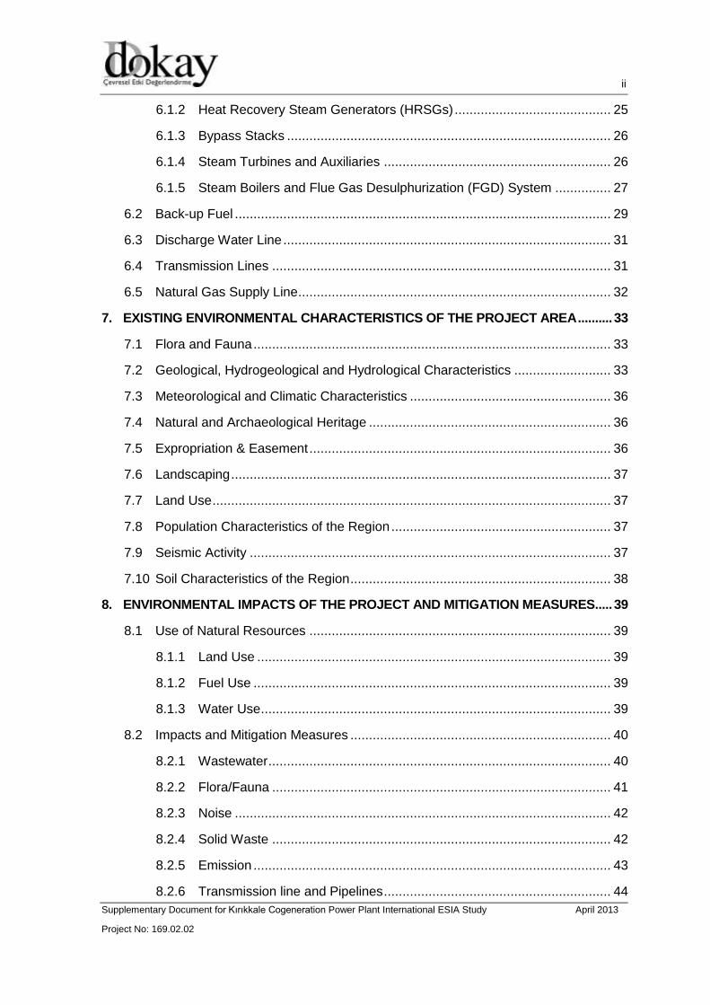
Figure 2. Typical Diagram of a Cogeneration Power Plant
The air taken from the atmosphere is passed through a filter system and enters into the
compressor part of the gas turbine, compressed here and then transmitted to the
combustion chamber. The fuel sprayed to the combustion chamber mixes with the
compressed air and burns.
The high-pressure gas produced by combustion, which is at a temperature above 1000 –
1100 °C, passes through the blades of the turbine and rotates it and thus, electric power is
generated by the generator connected to the turbine. The waste gas at the temperature of
500 – 600 °C exiting from the gas turbine is transmitted through an exhaust pipe to the
waste heat boiler. The exhaust gas entering into the waste heat boiler cools and then is
released to the atmosphere through the boiler flue.
In general, there are three different heat exchanger parts in a HRSG. In Rankine cycle,
water first enters into economizer and is heated up to a temperature slightly below the
saturation temperature, then is vaporized in the evaporator and this saturated steam is
given as superheated steam into the steam turbine after being re-heated in superheater.
This is a Rankine cycle for a single-stage pressure group of boiler-steam turbine.
However, steam-boiler turbine groups are located in the boiler separately for the three-
stage pressure level superheated or non-superheated. Rankine cycle forms different
cycles in itself depending upon these stages of pressure. The steam produced in the
HRSG and then entered into the steam turbine expands at the stages of turbine. Thus,
thermal energy transforms into mechanical energy. With the turbine driven, electric power
is generated by the generator connected to the turbine.

7 / 67 7 / 46
Supplementary Document for Kırıkkale Cogeneration Power Plant International ESIA Study April 2013
Project No: 169.02.02
7 / 52
The low temperature and pressure steam exiting from the steam turbine reaches to the
condenser and is transformed into water by being condensed by cooling system. Then, it
is sent, through the condensate pumps, to the feedwater tank for the removal of non-
condensed gas content in it. Water is re-sent from the feedwater tank to the waste heat
boiler through feedwater pumps. This way, it circulates between the Rankine closed-cycle
boiler, steam turbine and condenser. The main technical specifications of Kırıkkale CPP
are given in Table 1.
Table 1. Technical Specifications of Kırıkkale CPP
Parameters Unit Value
Plant
Installed Power MWe / MWt 233.7 / 404
Installed Power of Gas Turbine MWe 77.1
Installed Power of Steam Turbine MWe 79.5
Net Efficiency (minimum) % 52
Gas Turbine Pcs 2
Heat Recovery Steam Generator Pcs 2
Steam Turbine Pcs 1
Approximate Height of Flue M 50
Anticipated Electricity Generation
Amount kWh/year 2,030,000,000
Fuel Type - Natural Gas
Fuel Requirement m3/year 300,000,000
Some of the units planned to be established within the scope of Kırıkkale CPP are listed
below:
Steam Turbine Building HRSG
Main Transformer Stack
Auxiliary Transformer Gas Turbine
Electrical Building Auxiliary Boilers
Cooling Towers Deareator Feedwater Tank
Oil / Gas Module CEMS
Closed Cooling Water Pumps and Heat
Exchangers
Demineralized Water Tank
Inside Parking Lot Heavy Fuel Oil Tank
Workshop and Store Building Diesel Oil Tank
Control / Administration Building Circulating Water Pumps House

8 / 67 8 / 46
Supplementary Document for Kırıkkale Cogeneration Power Plant International ESIA Study April 2013
Project No: 169.02.02
8 / 52
5. PROJECT ALTERNATIVES AND CONFIGURATION OPTIONS
5.1 Turkey’s Energy Demand and Need for the Project
Fundamental goal of Turkey's energy policy is to decrease the country's external
dependence by making efficient, effective, safe and environmentally-conscious use of
energy and natural resources, and contributing to prosperity of the country. Within this
context, these are the fundamental elements of Turkey's energy policy:
Decreasing external dependence in energy,
Providing diversity of source, route and technology,
Maximum use of renewable energy sources,
Minimizing the effects on the environment,
Increasing our country's regional and global activity with regard to energy sector,
Increasing energy efficiency,
Making energy accessible by the consumers with regard to cost, time and amount,
Mobilizing the potentials of public and private sector with competitive market
conditions3.
Turkey is in a struggle to realize its development targets, increase social welfare and bring
the sector to a level that it can compete in the international market. This situation brought
a rapid increase of energy demand for years. Yearly energy demand has surpassed 109.3
million tons petroleum equivalent (tpe) in 2010. It is expected to reach 170 million tpe in
2015 and 222 million tpe in 2020. Yearly energy demand has surpassed 106.1 million tpe
in 2009. It is expected to reach 170 million tpe in 2015 and 222 million tpe in 2020. These
values indicate that energy demand will increase by approximately 6%. In 2009, coal had
the largest share in energy demand with 31%, natural gas followed it with 30.9%,
petroleum with 28.8%, and the remaining 9.3% was provided via renewable sources, with
hydraulic and other (wood)4.
There is a relation between development level and the share of electricity in final energy
consumption5. In 2010 our electricity consumption has increased by 7.92% compared to
the prior year (193.2 billion kWh) and it has reached 208.5 billion kWh, and our electricity
production has increased by 7.89% compared to the prior (194.81 billion kWh) year and it
has reached 210.18 billion kWh. It is seen that the latest estimated figures for electricity
demand issued by the Ministry of Energy and Natural Resources (2010-2019) shows that
3 Speech of Minister of Energy and Natural Resources, Taner YILDIZ, presenting 2011 Budget of the Ministry to TBMM
(Grand National Assembly of Turkey) General Assembly.
4 Ministry of Energy and Natural Resources “Blue Book”, Ankara 2011.
5 Güray B.Ş., “Supply-Demand Analysis, Expectations and Goals in Energy Sector”, 11th International Energy Arena,
November 2009.

9 / 67 9 / 46
Supplementary Document for Kırıkkale Cogeneration Power Plant International ESIA Study April 2013
Project No: 169.02.02
9 / 52
based on 2018, it is increased by 1.65% (for the High Demand) and 2.62% (for the Low
Demand) compared to the previous study (2019-2018). Revised numbers show that it will
reach 389.98 kWh for high demand scenarios, and 367.35 kWh for low demand scenarios
by the year 20196,7.
With regard to resources, as of 2011 44.7% of total electricity production is done with
natural gas, 18% by coal, 22.8% by hydraulic sources, 10% by imported coal, 2.2% by
other thermal fuels, 1.35% by wind and 0.47% by geothermal resources and biogas.
Compared to 2010, electricity production by wind has increased 62%, production by coal
has increased 17% while there is only a slight increase of 4% in natural gas and a 0.55%
increase hydraulic. Share of EÜAŞ (Electricity Production Inc.) was 49.2% in 2008; it has
decreased to 46.1% in 2009 and 45.4% in 2010. Remaining 54.6% of production is
provided by the private sector8. Growth numbers in the energy sector, which is among the
essential inputs of industry, is very high compared to developed countries. In the last 10
years, Turkey ranks second after China with regard to electricity and natural gas
consumption increase ratios.
As a result of the studies, Turkey’s potential local energy sources that were determined as
of the end of 2011 are shown in Table 2. Only lignite reserves have increased compared
to 2010 (from 8.4 billion tons to 11.4 billion tons (approximately 36% increase).
Table 2. Turkey Local Resources Potential as of 2009
Source Potential
Lignite 11.45 gigaton
Anthracite 1.34 gigaton
Asphaltite 82 gigaton
Crude Oil 6.72 billion barrel
Hydraulic 140,000 kWh/year
Natural Gas 21.86 billion m3
Wind 48,000 MW
Geothermal 31.500 MWt
Biomass 8.6 MTOE
Solar Energy 35 MTOE
Source: Ministry of Energy and Natural Resources, Sinem Çaynak presentation, 2011
If new investments will not be made and the problems of the industry will not be solved in
the forthcoming years, electric power deficit will increase incrementally and the deficit will
reach up to 144.7 billion kWh in 20169. The recent estimation studies of Turkish Electricity
6 TEİAŞ, Turkey Electricity Energy 10-Year Production Capacity Projection (2010-2019), October 2010.
7 TEİAŞ, Turkey Electricity Energy 10-Year Production Capacity Projection (2009-2018), June 2009.
8 TEİAŞ, 2010 Monthly Production Statistics
9 www.euas.gov.tr/_EUAS/Images/Birimler/apk/2009_yillikrapor.pdf

10 / 67 10 / 46
Supplementary Document for Kırıkkale Cogeneration Power Plant International ESIA Study April 2013
Project No: 169.02.02
10 / 52
Transmission Corporation (TEİAŞ) of the Ministry of Energy and Natural Resources
(MoENR) suggest the necessity of the new electricity generation plants. Based on the
values contained in the Projection Report for Turkish Electricity Energy 10-Year
Generation Capacity issued by MoENR and given in Table 3, Turkey’s average annual
electricity requirement has rapidly increased between 2011 and 2018.
Table 3. Projection for Energy Requirement of Turkey (Base Demand- High Scenario)
Year Peak Demand (MW) Increase (%) Energy Demand (106KWS) Increase (%)
2011 33,276 6.5 215,907 6.5
2012 35,772 7.5 232,101 7.5
2013 38,455 7.5 249,508 7.5
2014 41,339 7.5 268,221 7.5
2015 44,440 7.5 288,338 7.5
2016 47,728 7.4 309,675 7.4
2017 51,260 7.4 332,591 7.4
2018 55,053 7.4 357,202 7.4
Source: www.teias.gov.tr
Energy investments should be commissioned in timely manner to achieve this projection
and ensure the security and sustainability of energy supply. Otherwise, it will be inevitable
to face with the energy deficit in the forthcoming years.
5.1.1 No Action (Zero Option)
No action option is essential to understand whether the project is actually needed or not.
In addition, it gives the opportunity to compare with the other options. However, non-
realization of the Project does not meet the steam and energy requirement of the Tüpraş
Refinery and the growing energy demand of Turkey.
The existing Thermal Power Plant (TPP) in Kırıkkale Refinery is constructed in 1986. TPP
unit has been equipped with two 12MWe CTR12 type steam turbines and 21 MWe Nuovo
Pignone type steam turbine to supply Refinery electric demand. First and second turbine
has been built in 1986, third one (21MW) has been built in 2007. There are four 120 t/h
boilers in Kırıkkale Refinery burning Refinery Gas and Fuel Oil mixture.
The existing Plant located in Tüpraş refinery has adverse effects from environmental and
economic aspects. Energy efficiency of the current plant is lower than the planned CCGT
system’s efficiency. According to modeling studies, the Project’s emissions (NOx and CO)
are extremely lower than the limit values set forth by Turkish regulations. Natural gas is
used as the main fuel source which is environmentally friendly as compared with other
fuel types. Since the selected system will have back-up fuel; the Project guarantees the
continuity of energy supply to the Refinery in any emergency case, which brings an
advantage compared with the existing plant. Therefore, no action cannot be considered as
a preferable option.
5.1.2 Need for the Project
Fundamental goal of Turkey's energy policy is to decrease the country's external
dependence by making efficient, effective, safe and environmentally-conscious use of

11 / 67 11 / 46
Supplementary Document for Kırıkkale Cogeneration Power Plant International ESIA Study April 2013
Project No: 169.02.02
11 / 52
energy and natural resources, and contributing to prosperity of the country. Within this
context, these are the fundamental elements of Turkey's energy policy:
Decreasing external dependence in energy,
Providing diversity of source, route and technology,
Maximum use of renewable energy sources,
Minimizing the effects on the environment,
Increasing our country's regional and global activity with regard to energy sector,
Increasing energy efficiency,
Making energy accessible by the consumers with regard to cost, time and amount,
Mobilizing the potentials of public and private sector with competitive market
conditions10.
Tüpraş is the largest and leading industrial organization with its refining capacity of 28.1
million tons/year. Kırıkkale Cogeneration Power Plant having an installed power of 233.7
MWe will both serve to the Tüpraş which has a significant place in the national economy
and contribute to the resource diversity in Turkish energy market thus playing an
important role in solving the problem of energy deficit and ensuring the security of supply.
Accordingly, the Project has a considerable importance for the country.
5.2 Site Alternatives
The Power Plant will be installed adjacent to the Tüpraş Refinery. Seymenoba has
identified two possible sites. The first site (ALT-1) of approximately 85000 m2 at an altitude
of 705 m is located adjacent to the South Eastern corner of the Refinery alongside the
existing Hacılar substation. The second site (ALT-2) of approximately 114000 m2 at an
altitude of 730 m is located adjacent to the South Western corner of the Refinery and is
adjacent to the existing bulk oil storage tanks.
The key features of the two site alternatives are described respectively as follows:
5.2.1 Alternative 1
The site is adjacent to the existing substation / switchyard allowing existing cable
routes to the Refinery to be followed.
The site is closer to the interconnection points with the Refinery steam headers
allowing the pipe runs to be kept as short as possible. This will minimize losses
and reduce costs.
The site is closer to the interconnection points for the electrical supply to the
Refinery allowing cable runs to be as short as possible.
10
Speech of Minister of Energy and Natural Resources, Taner YILDIZ, presenting 2011 Budget of the Ministry to TBMM
(Grand National Assembly of Turkey) General Assembly.

12 / 67 12 / 46
Supplementary Document for Kırıkkale Cogeneration Power Plant International ESIA Study April 2013
Project No: 169.02.02
12 / 52
The site is close to the source of raw water supply from the nearby Kapulukaya
Dam. This is also of benefit for waste water discharge to the river.
The site altitude is lower than ALT-2 giving a slight increase in efficiency and
power output.
Access to the site is available from the Municipality road.
There are a number of headroom restrictions along the immediate route to the site.
Trunk road overbridge (4m) and overhead lines.
The topography of the site is quite varied and will require significant earth works to
establish the plant grade level.
An existing natural watercourse traverses the site.
The existing buried raw water supply pipeline (approximately 800 mm) to the
Refinery traverses the South Western corner of the site and buried treated water
discharge mains from the Refinery traverse the site in the North West.
5.2.2 Alternative 2
The site is on the opposite side of the Refinery to the connection point for the
electrical power and Refinery steam header interconnection points. This would
result in longer cable and pipe routes across the Refinery, increasing losses and
costs.
The site is remote from the Kızılırmak River and Kapulukaya Dam which will be
used as a raw water source and waste water discharge route.
The site altitude is higher than ALT-1 giving a slight reduction in efficiency and
power output.
Access to the site is available from the Municipality road network. The Municipality
road is surfaced and narrow. There is no direct surfaced or gravel road access
connecting the site to the Municipality road.
There is a single headroom restriction along the immediate route to the site from
overhead lines.
The topography of the site is gently sloping and is likely to require fewer
earthworks than is required for the ALT-1 site.
There is an earth dam / dyke feature which traverses the site.
5.2.3 Other Site Alternatives
Alternative project areas, different from the ALT-1 and ALT-2, have not been considered,
because main function of the Project is to serve Tüpraş Refinery with steam and energy.
Other site alternatives shall not be feasible in terms of supplying steam and energy to the
Refinery.
13 / 67 13 / 46
Supplementary Document for Kırıkkale Cogeneration Power Plant International ESIA Study April 2013
Project No: 169.02.02
13 / 52
5.2.4 Selected Project Area
ALT-1 has been selected regarding conditions described below;
Wastewater discharge location (Kızılırmak River) is closer as compared with the
ALT-2.
According to “Air Quality Assessment Studies for Alternative Project Sites Report”
prepared by DOKAY in May 2012, air quality modeling studies show that NOx
emissions are lower at ALT-1 than the emissions monitored at ALT-2.
Altitude is lower in ALT-1, providing increment in efficiency and power output.
ALT-1 is closer to the interconnection points with the Refinery steam headers.
5.3 Cooling Alternatives
In combined cycle power plants, steam turbine exhaust has to be condensed to preserve
the needed sub-atmospheric turbine exit pressure and to return the condensate to the
HRSG. The main requirement for cooling water is for condensing the steam at turbine
exhaust. Condensing (Cooling) alternatives are once-through cooling, wet (cooling tower)
cooling, dry cooling, and wet/dry (hybrid) cooling systems. For this specific site two
cooling methods has been considered; recirculation using cooling towers or air-cooled
condenser (ACC).
5.3.1 Wet Cooling
Wet cooling system consists of cooling tower in which the steam is condensed in water-
cooled shell/tube surface condensers. In a cooling tower system, warm water from the
condenser is delivered to a cooling tower in which the water is sprayed downwards
through nozzles into a flow of air which is forced upwards by a fan or fans. The cooling is
achieved by the evaporation which accounts for 65-85% of the total heat rejection.
In order to prevent an over-concentration of dissolved salts in the recirculating water,
which could cause scale formation on the condenser tubes, additional water has to be
discharged to waste. The water lost by evaporation and the discharge water is replaced
by make-up water. The total water loss is likely to be about 4 percent of the amount in
circulation.
Cooling towers can be categorized in two ways; natural and mechanical draft towers. A
typical natural draft wet cooling tower is presented in Figure 3.
Factors affecting the performance cost of a cooling tower; ambient air wet-bulb
temperature, airflow rate, fill type, and water quality.

14 / 67 14 / 46
Supplementary Document for Kırıkkale Cogeneration Power Plant International ESIA Study April 2013
Project No: 169.02.02
14 / 52
Figure 3. Typical Cooling Tower
Source: Applied Thermal Enginerering, 2006.
Advantages:
High system efficiency,
High energy output (in terms of MWe), and
Low capital cost.
Disadvantages:
Visible plume emissions,
Chemical dosing, and
High area requirement.
5.3.2 Dry Cooling
As the dry cooling system, direct cooling, air-cooled condenser (ACC), option has been
taken into consideration. In this cooling system, heat rejection to the environment consists
of a single step in which condensing of the steam takes place inside finned tubes. Tubes
15 / 67 15 / 46
Supplementary Document for Kırıkkale Cogeneration Power Plant International ESIA Study April 2013
Project No: 169.02.02
15 / 52
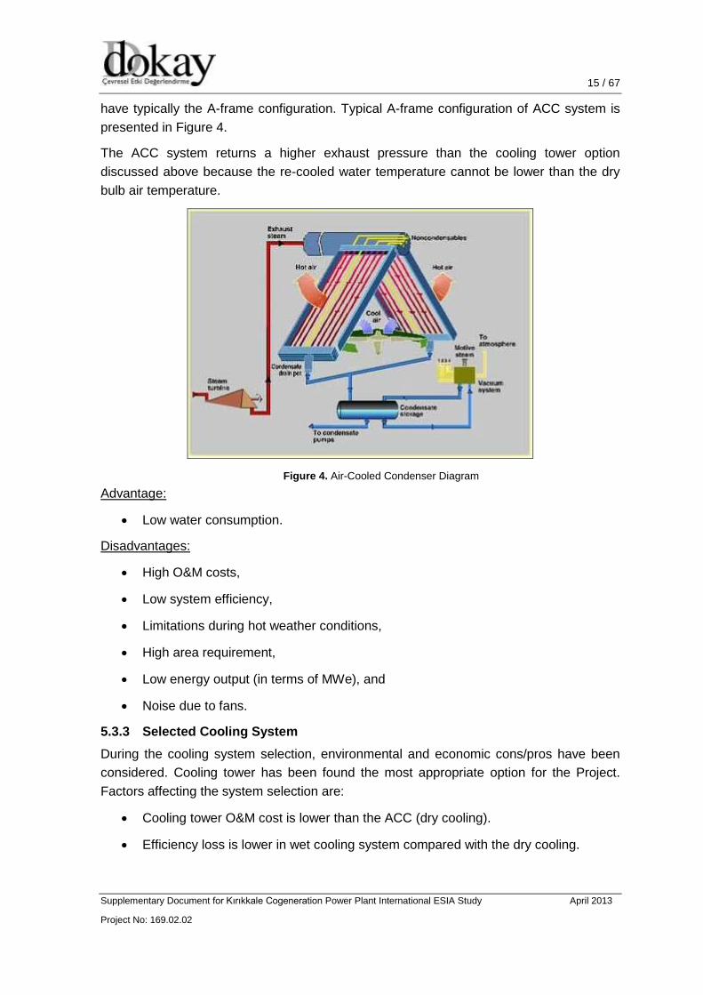
have typically the A-frame configuration. Typical A-frame configuration of ACC system is
presented in Figure 4.
The ACC system returns a higher exhaust pressure than the cooling tower option
discussed above because the re-cooled water temperature cannot be lower than the dry
bulb air temperature.
Figure 4. Air-Cooled Condenser Diagram
Advantage:
Low water consumption.
Disadvantages:
High O&M costs,
Low system efficiency,
Limitations during hot weather conditions,
High area requirement,
Low energy output (in terms of MWe), and
Noise due to fans.
5.3.3 Selected Cooling System
During the cooling system selection, environmental and economic cons/pros have been
considered. Cooling tower has been found the most appropriate option for the Project.
Factors affecting the system selection are:
Cooling tower O&M cost is lower than the ACC (dry cooling).
Efficiency loss is lower in wet cooling system compared with the dry cooling.

16 / 67 16 / 46
Supplementary Document for Kırıkkale Cogeneration Power Plant International ESIA Study April 2013
Project No: 169.02.02
16 / 52
Dry cooling system may have noise impact on near sensitive receptors because of
usage of fans.
Dry cooling is dependent on ambient air conditions (during hot seasons system’s
efficiency decreases).
Since Tüpraş refinery funded the construction of Kapulukaya Dam, Refinery has the right
to use the 6% of the raw water supplied from Kapulukaya Dam. Seymenoba has made a
protocol with Tüpraş to use the raw water. Therefore, water supply for the wet cooling
system shall not create concern about water supply to the system. Plant’s discharge
values can be seen in the Project’s water balance diagram in Figure 5.

17 / 67
Supplementary Document for Kırıkkale Cogeneration Power Plant International ESIA Study April 2013
Project No: 169.02.02
17 / 52
Figure 5. Water Balance Diagram of the Project
18 / 67 18 / 46
Supplementary Document for Kırıkkale Cogeneration Power Plant International ESIA Study April 2013
Project No: 169.02.02
18 / 52
5.4 Configuration Options
System options have been considered by taking into account some parameters such as
ambient conditions, turbine efficiency, cost, power output etc.
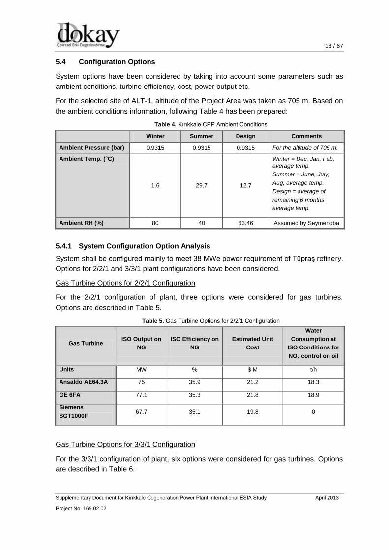
For the selected site of ALT-1, altitude of the Project Area was taken as 705 m. Based on
the ambient conditions information, following Table 4 has been prepared:
Table 4. Kırıkkale CPP Ambient Conditions
Winter Summer Design Comments
Ambient Pressure (bar) 0.9315 0.9315 0.9315 For the altitude of 705 m.
Ambient Temp. (°C)
1.6 29.7 12.7
Winter = Dec, Jan, Feb, average temp.
Summer = June, July,
Aug, average temp.
Design = average of
remaining 6 months
average temp.
Ambient RH (%) 80 40 63.46 Assumed by Seymenoba
5.4.1 System Configuration Option Analysis
System shall be configured mainly to meet 38 MWe power requirement of Tüpraş refinery.
Options for 2/2/1 and 3/3/1 plant configurations have been considered.
Gas Turbine Options for 2/2/1 Configuration
For the 2/2/1 configuration of plant, three options were considered for gas turbines.
Options are described in Table 5.
Table 5. Gas Turbine Options for 2/2/1 Configuration
Gas Turbine ISO Output on
NG
ISO Efficiency on
NG
Estimated Unit
Cost
Water
Consumption at
ISO Conditions for
NOx control on oil
Units MW % $ M t/h
Ansaldo AE64.3A 75 35.9 21.2 18.3
GE 6FA 77.1 35.3 21.8 18.9
Siemens
SGT1000F 67.7 35.1 19.8 0
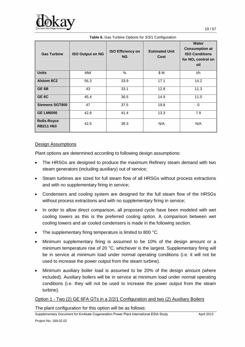
Gas Turbine Options for 3/3/1 Configuration
For the 3/3/1 configuration of plant, six options were considered for gas turbines. Options
are described in Table 6.
19 / 67 19 / 46
Supplementary Document for Kırıkkale Cogeneration Power Plant International ESIA Study April 2013
Project No: 169.02.02
19 / 52
Table 6. Gas Turbine Options for 3/3/1 Configuration
Gas Turbine ISO Output on NG ISO Efficiency on
NG
Estimated Unit
Cost
Water
Consumption at
ISO Conditions
for NOx control on
oil
Units MW % $ M t/h
Alstom 8C2 56.3 33.9 17.1 14.2
GE 6B 43 33.1 12.8 11.3
GE 6C 45.4 36.5 14.9 11.0
Siemens SGT800 47 37.5 19.8 0
GE LM6000 42.8 41.4 13.3 7.9
Rolls-Royce
RB211 H63 42.5 39.3 N/A N/A
Design Assumptions
Plant options are determined according to following design assumptions:
The HRSGs are designed to produce the maximum Refinery steam demand with two
steam generators (including auxiliary) out of service;
Steam turbines are sized for full steam flow of all HRSGs without process extractions
and with no supplementary firing in service;
Condensers and cooling system are designed for the full steam flow of the HRSGs
without process extractions and with no supplementary firing in service;
In order to allow direct comparison, all proposed cycle have been modeled with wet
cooling towers as this is the preferred cooling option. A comparison between wet
cooling towers and air cooled condensers is made in the following section.
The supplementary firing temperature is limited to 800 °C.
Minimum supplementary firing is assumed to be 10% of the design amount or a
minimum temperature rise of 20 °C, whichever is the largest. Supplementary firing will
be in service at minimum load under normal operating conditions (i.e. it will not be
used to increase the power output from the steam turbine).
Minimum auxiliary boiler load is assumed to be 20% of the design amount (where
included). Auxiliary boilers will be in service at minimum load under normal operating
conditions (i.e. they will not be used to increase the power output from the steam
turbine).
Option 1 - Two (2) GE 6FA GTs in a 2/2/1 Configuration and two (2) Auxiliary Boilers
The plant configuration for this option will be as follows:

20 / 67 20 / 46
Supplementary Document for Kırıkkale Cogeneration Power Plant International ESIA Study April 2013
Project No: 169.02.02
20 / 52
Two GE 6FA gas turbines;
Two dual pressure HRSGs each rated to produce 50% of the Refinery steam flow.
Supplementary firing of the HRSGs is not required in this case;
One condensing extraction steam turbine rated for a maximum output without steam
extraction of 75 MW;
One condenser, wet cooling towers (with ACC as an option); and
Two auxiliary boilers each sized for 50% of the Refinery steam load.
Option 2 - Three (3) Siemens ST800 GTs in a 3/3/1 Configuration
For this option, auxiliary boilers are not included. Planned equipment installation is
described below:
Three Siemens SGT800 gas turbines;
Three dual pressure HRSGs equipped with supplementary firing and forced draft
fans. Each HRSG will be capable of supplying 100% of the Refinery steam
requirements. NOTE: It is not the intention that HRSGs should be able to operate with
their associated GT out of service (i.e. the HRSGs are not auxiliary fired);
One condensing extraction steam turbine rated for a maximum output without steam
extraction of 55 MW; and
One condenser, wet cooling towers (with ACC as an option).
Option 3 – Three (3) Siemens SGT800 GTS in a 3/3/1 Configuration and two (2) Auxiliary
Boilers
The Plant with three (3) units and two (2) auxiliary boilers would have the following
equipment installed:
Three Siemens SGT800 gas turbines;
Three dual pressure HRSGs equipped with supplementary firing, each rated to
produce 33.4% of the Refinery steam demand;
One condensing extraction steam turbine rated for a maximum output without steam
extraction of 62MW;
One condenser, wet cooling towers (with ACC as an option);
Two auxiliary boilers each rated to produce 33.4% of the Refinery steam demand.
Summary of Modeling Results for 3 Options
According to modeling study, a summary of results for three options is given in Table 7:

21 / 67 21 / 46
Supplementary Document for Kırıkkale Cogeneration Power Plant International ESIA Study April 2013
Project No: 169.02.02
21 / 52
Table 7. Modeling Results of Configuration Options
Option 1 Option 2 Option 3
Gas Turbine - GE 6FA SGT800 SGT800
Configuration No. GT/HRSG/ST
+ Aux. 2/2/1 + 2 3/3/1 3/3/1 + 2
Power Output MW 193 170 163
Efficiency % 45.7 44.8 44.5
Capital Cost US $M 223.077 261.963 217.075
Cost per MW US $M / MW 1.16 1.54 1.33
5.4.2 Selected Plant Configuration
Result of the modeling study shows that the Option1 has the highest power output and
efficiency of the options modeled and the lowest number of gas turbines installed. The
HRSGs for the plant do not include supplementary firing and consequently could be
considered the simplest cycle design.
The relatively large size of gas turbines that is required and 2/2/1 configuration means that
the flexibility of this plant options is limited.
The new and clean power output of the modeled GE 6FA gas turbine is approximately 70
MWe, allowing significant headroom for degradation to meet the maximum Refinery
demand of 38 MWe.
Option 1 is the least flexible, but has the highest efficiency and power output with a
competitive capital cost, giving the best cost per MW.
Option 2 has good flexibility, but has the highest capital cost and the lowest efficiency with
a lower power output than Option 1, giving the highest cost per MW.
Option 3 has good flexibility and the lowest capital cost, but has a lower efficiency and
power output than Option 1, with the cost per MW being higher than Option 1.
The Plant configuration selection was carried out considering parameters such as
efficiency, capital cost, flexibility, total power output and cost per MW. From the
comparison described above, Option 1 (2/2/1 + 2) has been selected for the most feasible
configuration of all.
5.4.3 Option 4 (Enhancement of the Selected Configuration)
This option is considered to be changing the number of Steam Boilers from two (2) boilers
to one (1) boiler. In the absence of gas turbines, HRSG will run with Fresh Air Firing
(FAF). For the selected Option 3, steam supply of HRSG unit (in the absence of gas
turbines) is 100 t/h. For this Option 4; since there will be one (1) steam boiler, steam
capacity of HRSGs shall be increased from 100 t/h to 181 t/h in the absence of gas
turbines. This capacity increase will meet the steam requirement of the Refinery.
22 / 67 22 / 46
Supplementary Document for Kırıkkale Cogeneration Power Plant International ESIA Study April 2013
Project No: 169.02.02
22 / 52
This option also involves the option of change Heavy Fuel Oil (HFO) as back-up fuel for
Steam Boiler to Diesel Fuel Oil (DFO) in order to reduce the treatment required for Steam
Boiler Flue gas. Changing back-up fuel to DFO reduces the Flue Gas treatment with
consequent cost and efficiency improvements.
With the usage of DFO as back-up fuel, HFO will not be required in the Kırıkkale CPP so
that DFO system capacity will be increased to withstand simultaneous supply to Gas
Turbines and Steam Boiler.
Steam Boiler auxiliaries
Flue Gas Desulphurization System: The DFO composition and particularly the sulphur
content don’t require installing FGD unit to comply with the SOx emission limits.
Therefore, FGD unit with all its auxiliaries can be removed, and consequently the
design, operation and maintenance will be significantly simplified. DFO fuel gas
treatment will be reduced to a filtration unit to comply with the particulate matter
emission limit.
DFO System: DFO storage capacity will be increased to contain the volume
equivalent to three (3) days of the plant operating in island mode and exporting the
maximum power and steam demands to the Refinery. The capacity of the DFO main
pumps will be increased to withstand the DFO flow required for Steam Boiler.
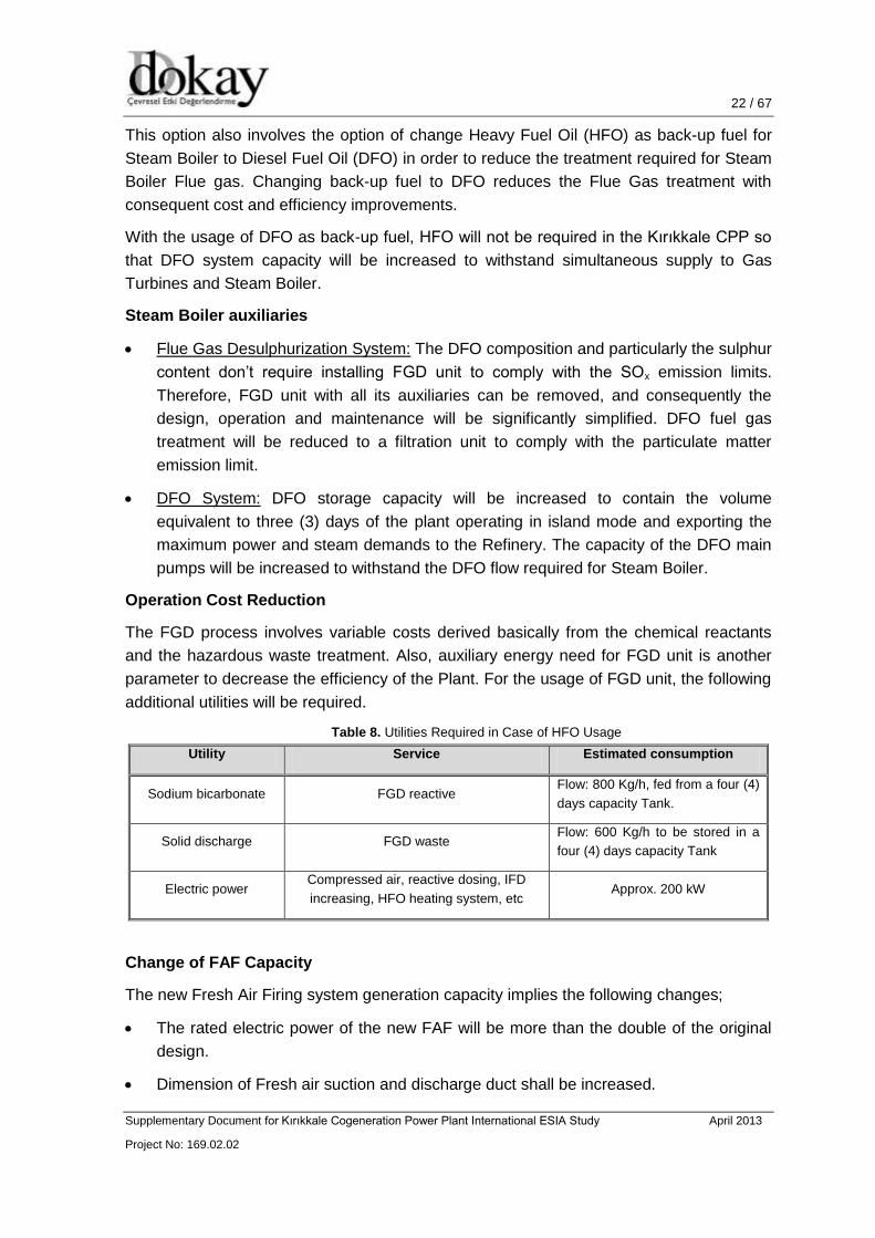
Operation Cost Reduction
The FGD process involves variable costs derived basically from the chemical reactants
and the hazardous waste treatment. Also, auxiliary energy need for FGD unit is another
parameter to decrease the efficiency of the Plant. For the usage of FGD unit, the following
additional utilities will be required.
Table 8. Utilities Required in Case of HFO Usage
Utility Service Estimated consumption
Sodium bicarbonate FGD reactive Flow: 800 Kg/h, fed from a four (4)
days capacity Tank.
Solid discharge FGD waste Flow: 600 Kg/h to be stored in a
four (4) days capacity Tank
Electric power Compressed air, reactive dosing, IFD
increasing, HFO heating system, etc Approx. 200 kW
Change of FAF Capacity
The new Fresh Air Firing system generation capacity implies the following changes;
The rated electric power of the new FAF will be more than the double of the original
design.
Dimension of Fresh air suction and discharge duct shall be increased.

23 / 67 23 / 46
Supplementary Document for Kırıkkale Cogeneration Power Plant International ESIA Study April 2013
Project No: 169.02.02
23 / 52
The burner’s capacity is increased to approximately double capacity of the original
design.
HRSG Fuel Gas condition system capacity increases for new maximum fuel gas
consumption.
A Flue gas treatment system, Selective Catalytic Reduction (SCR), is included to
comply with the NOx emission limit values. The new SCR system will include the
following:
Urea Storage;
Dissolver Tank;
Urea transfer system including pumps, pipes, and auxiliaries;
Urea solution Tank;
Urea solution transfer system with pumps and auxiliaries;
Vaporizer;
Blowers;
Urea injection skid; and
Catalyst reactor
Environmental Aspect
Since the sulphur content of the DFO is less than HFO, FGD unit will no longer be needed
which is a plus as compared with the selected configuration. Therefore, daily solid waste
(600 kg/h) of the FGD unit will be eliminated.
Use of SCR unit will decrease the NOx emission of the new configuration. Moreover, use
of SCR unit is considered as BAT.
Another advantage of DFO usage in Steam Boiler is the elimination of a storage tank for
HFO which requires extra area apart from the DFO storage tank.

24 / 67 24 / 46
Supplementary Document for Kırıkkale Cogeneration Power Plant International ESIA Study April 2013
Project No: 169.02.02
24 / 52
6. TECHNICAL SPECIFICATIONS
According to selected plant configuration and cooling system, each component of the
Kırıkkale CPP will be described specifically under this section.
6.1 EQUIPMENT TECHNICAL ISSUES
Main equipment that will be described under this section:
Gas Turbines
Heat Recovery Steam Generators (HRSGs)
Bypass Stacks
Steam Turbines and Auxiliaries
Steam Boilers and Flue Gas Desulphurization (FGD) System
6.1.1 Gas Turbines
The configuration of the MS 6111 FA (GE 6FA) is a single shaft, bolted rotor with the
generator connected to the gas turbine through a speed reduction gear at the compressor
or “cold” end. This feature provides for an axial exhaust to optimize the plant arrangement
for combined cycle or waste heat recovery applications. Illustrated version of GE 6FA
turbine is given in Figure 6.
Figure 6. GE 6FA Gas Turbine
Compressor
The compressor is an 18 stage axial flow design with 1 row of modulating inlet guide
vanes and a pressure ratio of 15.8:1 in ISO conditions. Interstage extraction is used for
cooling and sealing air (turbine nozzles, wheelspaces) and for compressor surge control

25 / 67 25 / 46
Supplementary Document for Kırıkkale Cogeneration Power Plant International ESIA Study April 2013
Project No: 169.02.02
25 / 52
during start-up/shutdown. Construction employs 15 full length tie bolts that compress the
discs at the bolt circle thereby forming a rigid rotor. The discs are centered by means of
rabbets. The compressor blades are attached to the discs with locked-in dovetails. High
strength, corrosion resistant GTD450 stainless steel blading material is provided on the
first nine stages. The remaining blading, except stage 17 stator and EGV, is of high
strength AISI 403+Cb alloy. Stage 17 stator and EGV are cast from high strength 403CB.
Because the blading material in the compressor has high corrosion resistance, a coating
is not required. The compressor wheel webs are coated with corrosion resistant paint.
Combustion System
A reverse flow, six chamber second generation Dry Low NOx combustion system is
standard with six fuel nozzles per chamber. Two retractable spark plugs and four flame
detectors are a standard part of the combustion system. Crossfire tubes connect each
combustion chamber to adjacent chambers on both sides. Transition pieces are cooled by
air impingement. Thermal barrier coatings are applied to the inner walls of the combustion
liners and transition pieces for longer inspection intervals. Each chamber, lines and
transition piece can be individually replaced.
Turbine Section
The turbine section has three stages with air-cooling on all three nozzle stages and the
first and second bucket stages. The first stage bucket has an advanced cooling system to
withstand the higher firing temperature. It utilizes turbulated serpentine passages with
cooling air discharging through the tip, leading and trailing edges. The buckets are
designed with long shanks to isolate the turbine wheel rim from the hot gas path and
integral tip shrouds are incorporated on the second and third stages to eliminate bucket
fatigue concerns and to improve heat rate. The first stage has a separate, two piece
casing shroud that permits reduced tip clearances.
The rotor is a single shaft, two bearing design with high torque capability incorporating
internal air-cooling for the turbine section. Both the compressor and turbine sections are
constructed of individually rabbeted discs held with bolts. Each turbine wheel is
prestressed with a hot spin process to reduce the operating stresses. The direction of
shaft rotation is counter-clockwise when facing the gas turbine output flange (compressor
forward shaft flange). The load gear reverses the direction of rotation as it drives the
generator rotor. For field changeout, the gas turbine rotor is handled as one piece. The
turbine buckets (rotating blades) can be changed in sets or individually without any field
balancing of the rotor.
6.1.2 Heat Recovery Steam Generators (HRSGs)
The HRSG units will be double pressure type, comprising economizer, drum, evaporator
and superheater sections. The HRSG shall be designed to accept the full gas flow from
the GT exhaust and including any additional gas flow arising from the supplementary firing
system. The HRSG supporting structure, together with the steelwork for support of the
steam drums and access stairways shall be clad by sheeting.
26 / 67 26 / 46
Supplementary Document for Kırıkkale Cogeneration Power Plant International ESIA Study April 2013
Project No: 169.02.02
26 / 52
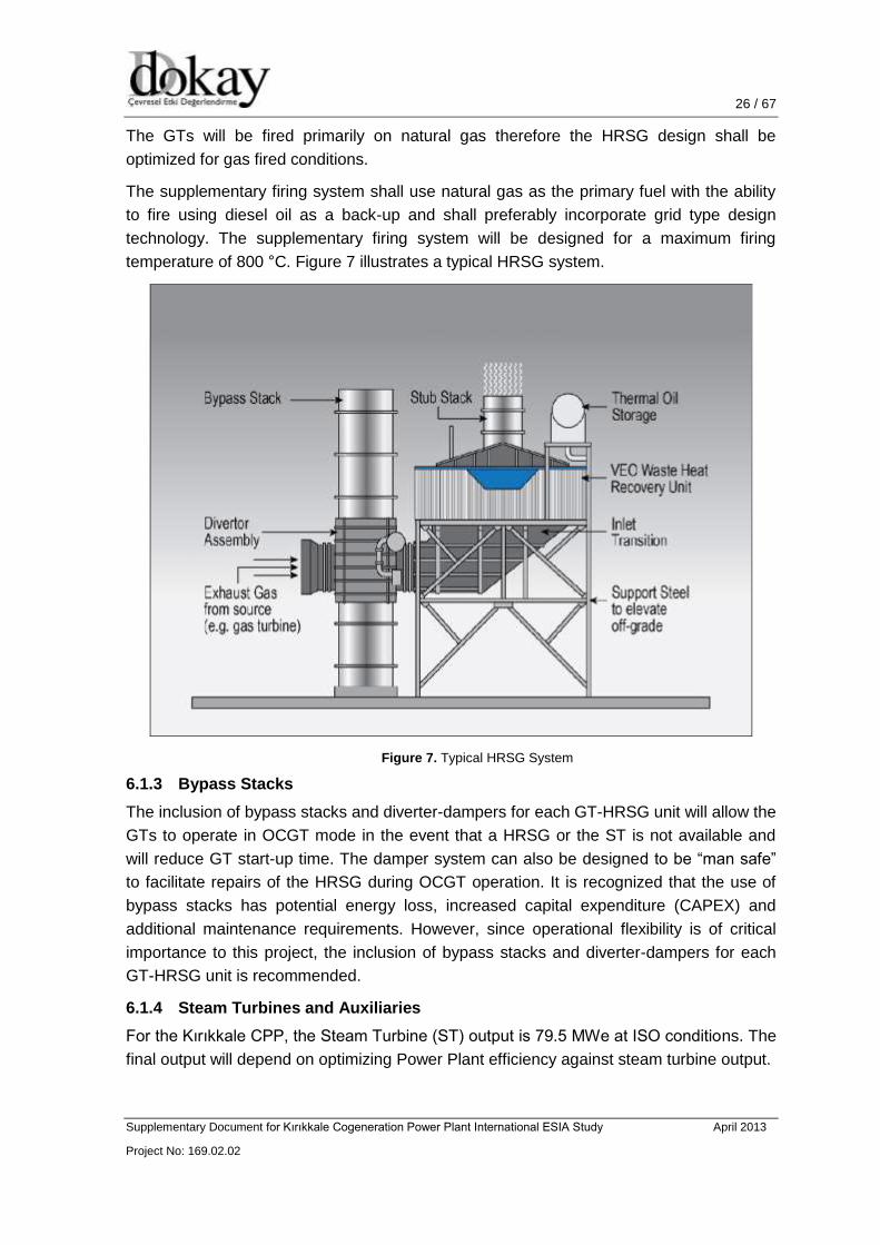
The GTs will be fired primarily on natural gas therefore the HRSG design shall be
optimized for gas fired conditions.
The supplementary firing system shall use natural gas as the primary fuel with the ability
to fire using diesel oil as a back-up and shall preferably incorporate grid type design
technology. The supplementary firing system will be designed for a maximum firing
temperature of 800 °C. Figure 7 illustrates a typical HRSG system.
Figure 7. Typical HRSG System
6.1.3 Bypass Stacks
The inclusion of bypass stacks and diverter-dampers for each GT-HRSG unit will allow the
GTs to operate in OCGT mode in the event that a HRSG or the ST is not available and
will reduce GT start-up time. The damper system can also be designed to be “man safe”
to facilitate repairs of the HRSG during OCGT operation. It is recognized that the use of
bypass stacks has potential energy loss, increased capital expenditure (CAPEX) and
additional maintenance requirements. However, since operational flexibility is of critical
importance to this project, the inclusion of bypass stacks and diverter-dampers for each
GT-HRSG unit is recommended.
6.1.4 Steam Turbines and Auxiliaries
For the Kırıkkale CPP, the Steam Turbine (ST) output is 79.5 MWe at ISO conditions. The
final output will depend on optimizing Power Plant efficiency against steam turbine output.
27 / 67 27 / 46
Supplementary Document for Kırıkkale Cogeneration Power Plant International ESIA Study April 2013
Project No: 169.02.02
27 / 52
The ST shall be sized for full condensing mode to maximize power output when the
Refinery is shutdown (i.e. it will accept the maximum amount of steam produced by the
HRSG when the extractions to the Refinery are closed).
The steam turbine generator and all of its auxiliary and ancillary plant shall be placed in a
dedicated ventilated steam turbine building.
6.1.5 Steam Boilers and Flue Gas Desulphurization (FGD) System
6.1.5.1. Steam Boilers
Two (2) Steam Boilers will be installed to supply the maximum steam required for the
Refinery, even if no Gas Turbine are running. Boilers allow steam production up to 109 t/h
and steam temperature 370 °C. Fuel gas consumption of Boilers is estimated to be 6900
kg/h (at 100% MCR) where HFO consumption shall be 8400 kg/h (at 100% MCR).
Possible operation period of Steam Boilers with HFO is estimated to be 5 minutes /
month.
The furnaces of boilers shall be of Monowall construction and consist of welded fin-tube
panels. Burners are mounted on the furnace front wall covered by refractory. The
convection banks of Steam Boilers are made up of bare curved tubes expanded in the
upper and lower drums. The expansion is achieved using a pneumatic or electrical
expanding machine with torque limit in the drills mechanized on the drums with simple or
double grooving depending on the design pressure of the unit. The convection bank tubes
are in line. The drums of Steam Boilers are of completely solid welded construction. The
drum ends are of semi-elliptical section and supplied with elliptical access of 305 x 406
mm at both ends.
The exhaust system of the Steam Boilers (two (2) boilers each having 95 MWt power) will
have two (2) independent stacks (equipped with continuous emission monitoring system
for NOx, dust and SOx) for the Steam boilers. Therefore exhaust system will consist of two
(2) independent FGD in order to comply with emission when operating with Heavy Fuel Oil
(HFO).
6.1.5.2. Flue Gas Desulphurization (FGD) System
The FGD system is designed as a dry FGD with sodium bicarbonate injection. The
injection of the reagent is realized in the flue gas duct downstream the boiler just before
the fabric filters. The dry reactor allows the reagent get into contact with the gas during the
necessary treatment time (approximately 2 seconds). The reaction will be finalized in the
fabric filers where the solid residue will be accumulated prior to be deposited in waste silo.
With the planned equipment, a desulphurization efficiency of 99% can be achieved. The
higher desulphurization efficiency can be achieved by only increasing the reagent feed to
the FGD system.
The concentration of dust in the flue gas leaving the FGD absorber is cleaned by the low
pressure pulse jet filter to a dust content of below 20 mg/Nm3, dry (at 6% O2).

28 / 67 28 / 46
Supplementary Document for Kırıkkale Cogeneration Power Plant International ESIA Study April 2013
Project No: 169.02.02
28 / 52
The absorber is arranged downstream of the boiler. The absorber is an empty vertical flue
gas duct with venturi shaped nozzles which create the fluidized bed mixture of lime, re-
circulated desulphurization products and fly ash.
The absorption product, which mainly consists of calcium sulphite (CaSO3 x ½ H2O),
calcium sulphate (CaSO4 x ½ H2O), limestone (CaCO3) and fly ash is separated from the
clean gas in the downstream low pressure pulse jet filters.
The product is re-circulated back to the absorber via air-slides to prolong the solids
retention time of the sorbent. This aims at reducing the Ca/S molar ratio of the process.
The Ca/S molar ratio is approximately 1.2-1.8 (or higher, depending on raw as ash
content) at the requested data and desulphurization efficiency of approximately 80%.
With the planned equipment, a desulphurization efficiency of 99% can be achieved. The
higher desulphurization efficiency can be achieved by only increasing the reagent feed to
the FGD system. Guaranteed emission values are given in 9.1.
The concentration of dust in the flue gas leaving the FGD absorber is cleaned by the low
pressure pulse jet filter to a dust content of below 20 mg/Nm3, dry (at 6% O2).
Technical Features of the FGD System
Absorber:
Inside the absorber, which is an empty vertical flue gas duct with venture shaped nozzles,
a fluidized bed exist of material from ash, absorbent and FGD reaction products. To
achieve the optimal reaction temperature, water will be sprayed into the absorber by spill
back nozzles.
The absorber is made from normal mild steel without any internal fixed or moving parts.
No corrosion protection has to be provided in the absorber. Due to the high reactive solids
loading the inner areas of the absorber are continuously cleaned so that corrosive scaling
cannot stick on the inner surface.
Absorbent handling and storage:
FGD process is calculated with feeding of the reagent, which is the basis for
desulphurization up to emission limit value. Reagent will be delivered by trucks, and
stored in a silo. Through a pneumatic conveying system the reagent is transported to a
day silo which is situated close to the CFB absorber.
Fabric Filter:
A Fabric Filter (or ESP) is used for de-dusting the flue gas downstream the absorber.
Re-heating system:
The FGD system is typically operating between 75 and 85 °C, which causes a clean gas
temperature at stack entrance of approximately 80 to 90 °C. Additional flue gas re-heating
is not necessary. The optimum process temperature in the FGD absorber is directly
controlled within the CFB FGD system by water injection.

29 / 67 29 / 46
Supplementary Document for Kırıkkale Cogeneration Power Plant International ESIA Study April 2013
Project No: 169.02.02
29 / 52
Ducts and Stack:
The stack does not need some additional protection against i.e. corrosion.
Water / waste water:
Duct pollutants such as SO2 and SO3 will be removed by the following reaction:
NaHCO3 + SO2 + SO3 Na2SO3 + Na2SO4 + H2O + CO2
Estimated solid waste amount is 600 kg/h for the maximum steam production.
Description of the Planned FGD System
The reagent shall be delivered by trucks and stored in a storage silo, sized for 7 days
storage time.
The sorbent shall be of quality suitable for use in the FGD system, with an adequate
BET index.
The fresh sorbent shall be sent directly to the reactor by pneumatic conveying. The
reagent storage silo is provided with a flat type fluidized bottom, with fluidization
ensured by two (2) 100% dedicated blowers.
The reagent is transferred by one pneumatic conveying line, sized for the maximum
demand of the two units simultaneously operating at MCR, to one daily bin sized for
24 hours operation of two boilers at MCR conditions.
The fresh lime is fed this bin to the CFB reactor via-air-slides, one (1) 100% duty.
The flue gas from the CFB reactor goes into the fabric filter for the solids separation.
Via a main air-slide arranged below the filter hoppers, the solids recovered from the
fabric filter are recirculated into the CFB reactor to utilize the non-reacted lime
fraction.
A part of this solid stream will be directed, via a secondary air-slide provided with a
flow-regulation valve, into an ash surge bin common to two boiler units, from where
the ash will be pneumatically transported to the by-product silo.
The surge hopper doesn’t require long storage capacity: 4 hours operation storage
time, for two boilers at 100% MCR can be provided.
The storage silo will be utilized to store the end products.
The proposed configuration provides for all necessary redundancies to guarantee the
requested steam plant availability.
6.2 Back-up Fuel
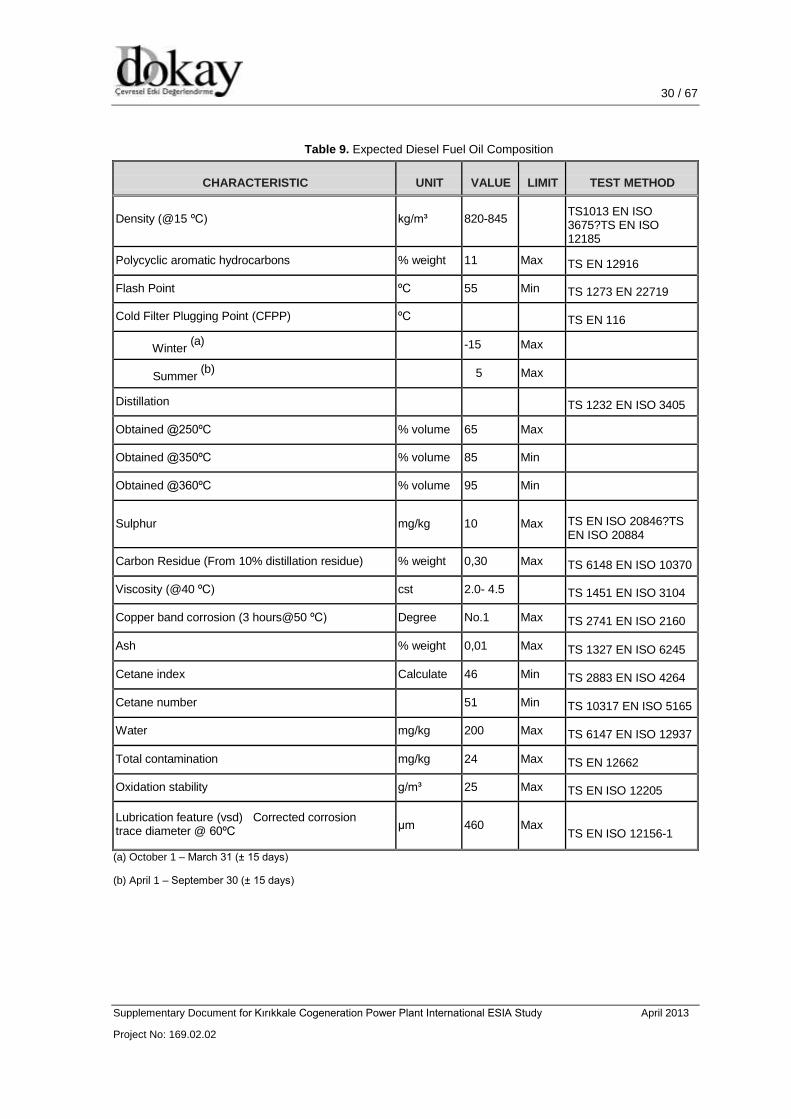
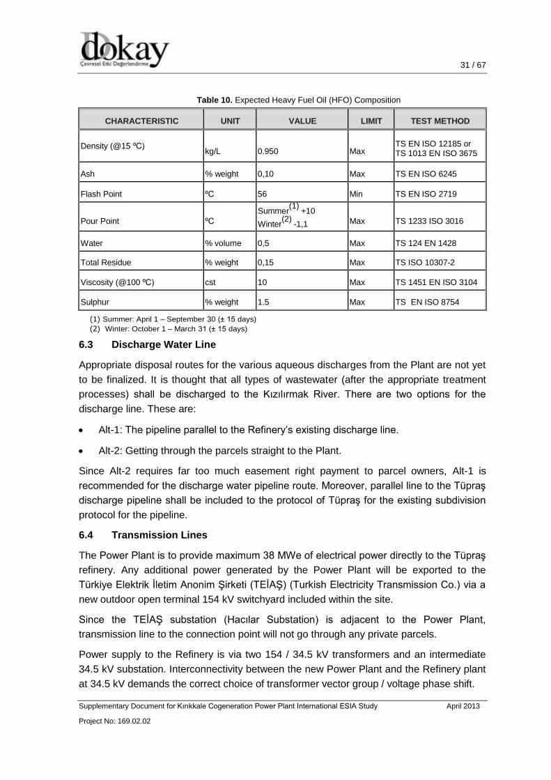
Kırıkkale CPP will use natural gas as the primary fuel source. Back-up fuel usage includes
Diesel Fuel Oil and Heavy Fuel Oil. Composition of back-up fuel sources is tabulated and
explained in Table 9 and Table 10.
30 / 67 30 / 46
Supplementary Document for Kırıkkale Cogeneration Power Plant International ESIA Study April 2013
Project No: 169.02.02
30 / 52
Table 9. Expected Diesel Fuel Oil Composition
CHARACTERISTIC
UNIT
VALUE
LIMIT
TEST METHOD
Density (@15 ºC)
kg/m³
820-845
TS1013 EN ISO 3675?TS EN ISO 12185
Polycyclic aromatic hydrocarbons % weight 11 Max TS EN 12916
Flash Point ºC 55 Min TS 1273 EN 22719
Cold Filter Plugging Point (CFPP) ºC
TS EN 116
Winter (a)
-15 Max
Summer (b)
5 Max
Distillation
TS 1232 EN ISO 3405
Obtained @250ºC % volume 65 Max
Obtained @350ºC % volume 85 Min
Obtained @360ºC % volume 95 Min
Sulphur
mg/kg
10
Max
TS EN ISO 20846?TS EN ISO 20884
Carbon Residue (From 10% distillation residue) % weight 0,30 Max TS 6148 EN ISO 10370
Viscosity (@40 ºC) cst 2.0- 4.5 TS 1451 EN ISO 3104
Copper band corrosion (3 hours@50 ºC) Degree No.1 Max TS 2741 EN ISO 2160
Ash % weight 0,01 Max TS 1327 EN ISO 6245
Cetane index Calculate 46 Min TS 2883 EN ISO 4264
Cetane number
51 Min TS 10317 EN ISO 5165
Water mg/kg 200 Max TS 6147 EN ISO 12937
Total contamination mg/kg 24 Max TS EN 12662
Oxidation stability g/m³ 25 Max TS EN ISO 12205
Lubrication feature (vsd) Corrected corrosion trace diameter @ 60ºC
µm
460
Max
TS EN ISO 12156-1
(a) October 1 – March 31 (± 15 days)
(b) April 1 – September 30 (± 15 days)
31 / 67 31 / 46
Supplementary Document for Kırıkkale Cogeneration Power Plant International ESIA Study April 2013
Project No: 169.02.02
31 / 52
Table 10. Expected Heavy Fuel Oil (HFO) Composition
CHARACTERISTIC UNIT VALUE LIMIT TEST METHOD
Density (@15 ºC) kg/L
0.950
Max
TS EN ISO 12185 or TS 1013 EN ISO 3675
Ash % weight 0,10 Max TS EN ISO 6245
Flash Point ºC 56 Min TS EN ISO 2719
Pour Point
ºC
Summer(1)
+10
Winter(2)
-1,1
Max
TS 1233 ISO 3016
Water % volume 0,5 Max TS 124 EN 1428
Total Residue % weight 0,15 Max TS ISO 10307-2
Viscosity (@100 ºC) cst 10 Max TS 1451 EN ISO 3104
Sulphur % weight 1.5 Max TS EN ISO 8754
(1) Summer: April 1 – September 30 (± 15 days)
(2) Winter: October 1 – March 31 (± 15 days)
6.3 Discharge Water Line
Appropriate disposal routes for the various aqueous discharges from the Plant are not yet
to be finalized. It is thought that all types of wastewater (after the appropriate treatment
processes) shall be discharged to the Kızılırmak River. There are two options for the
discharge line. These are:
Alt-1: The pipeline parallel to the Refinery’s existing discharge line.
Alt-2: Getting through the parcels straight to the Plant.
Since Alt-2 requires far too much easement right payment to parcel owners, Alt-1 is
recommended for the discharge water pipeline route. Moreover, parallel line to the Tüpraş
discharge pipeline shall be included to the protocol of Tüpraş for the existing subdivision
protocol for the pipeline.
6.4 Transmission Lines
The Power Plant is to provide maximum 38 MWe of electrical power directly to the Tüpraş
refinery. Any additional power generated by the Power Plant will be exported to the
Türkiye Elektrik İletim Anonim Şirketi (TEİAŞ) (Turkish Electricity Transmission Co.) via a
new outdoor open terminal 154 kV switchyard included within the site.
Since the TEİAŞ substation (Hacılar Substation) is adjacent to the Power Plant,
transmission line to the connection point will not go through any private parcels.
Power supply to the Refinery is via two 154 / 34.5 kV transformers and an intermediate
34.5 kV substation. Interconnectivity between the new Power Plant and the Refinery plant
at 34.5 kV demands the correct choice of transformer vector group / voltage phase shift.

32 / 67 32 / 46
Supplementary Document for Kırıkkale Cogeneration Power Plant International ESIA Study April 2013
Project No: 169.02.02
32 / 52
Appropriate transmission line route is not yet to be finalized. Two options are considered
within this manner:
Opt-1 is the transmission line going around the Refinery area.
Opt-2 is the transmission line passing through the security zone of the Refinery.
According to Opt-1, transmission line goes around the Refinery area so that earth works
for this option requires large amount of excavation work. It is recommended to choose the
Opt-2 for the ease of earth works and economic issues (since Opt-2 requires shorter
transmission line).
6.5 Natural Gas Supply Line
The installed power of the project is 233.7 MWe and 300,000,000 m3 of natural gas has
been annually planned to be consumed. There are two options for the supply of natural
gas.
A new BOTAŞ pressure relief and measurement station (PRMS), which is 1200 m far
from the Kırıkkale CPP, will be constructed for natural gas which will be used as fuel
in the power plant. Natural gas supply from the BOTAŞ PRMS is considered as the
Opt-1.
At the South border of the Tüpraş Refinery, branch of the BOTAŞ PRMS is located.
The branch station is located within the borders of the Refinery. Natural gas supply
from this station is the Opt-2.
Since Opt-2 is located within the borders of Tüpraş Refinery, there shall not be
environmental and socially negative impact of the Opt-2. Therefore, Opt-2 is
recommended as the natural gas supply station. Seymenoba shall perform detailed
engineering studies to determine the exact route for the chosen option.

33 / 67 33 / 46
Supplementary Document for Kırıkkale Cogeneration Power Plant International ESIA Study April 2013
Project No: 169.02.02
33 / 52
7. EXISTING ENVIRONMENTAL CHARACTERISTICS OF THE PROJECT AREA
7.1 Flora and Fauna
The Project site and the impact area are under the continental climatic conditions.
Therefore, dominant habitat of vegetation is steppe. During the international evaluations,
the categories and criteria set out in the Red List of Threatened Species (IUCN, 2011)
issued by International Union for Conservation of Nature, the Convention on International
Trade in Endangered Species of Wild Fauna and Flora (CITES, 2004) and Convention on
the conservation of European wildlife and natural habitats (BERN, 2002) have been
evaluated and the danger categories and protected status identified for each species.
In the examination carried out at national level, the decisions made by the Central Hunting
Commission (CHC) are evaluated for all fauna groups identified. Lists of different status
are formed based on the CHC decisions made by the commission which convenes each
year. Annex lists contained in CHC decisions:
ANNEX I: Wild Animals Protected by the Ministry of Environment and Forestry
ANNEX II: Game Animals Protected by the Central Hunting Commission
ANNEX III: Game Animals the hunting of which is permitted by the Central Hunting
Commission for specified periods.
Plant, amphibian, reptile, bird and mammal species encountered and likely to be
encountered due to the habitat characteristics at the project site and its area of influence
are identified during the National EIA studies, and included to the National EIA Report.
At all stages of the project, protection measures of the BERN convention will be complied
with for the fauna species set out in Annex-2 and Annex-3 of BERN Convention and the
provisions of the articles 6 and 7 of the same will be applied.
7.2 Geological, Hydrogeological and Hydrological Characteristics
The territories of the province, in general, consist of the medium-height mountains split by
stream valleys. The elevation difference between the stream beds and hills is slight. The
mountains became round and sometimes pointed hills by being split by the deep valleys
on each direction. The southern territories of the province being the coastline of Kizilirmak
in the first place are formed by alluvial deposit. Granites are commonly seen in the site
extending up to Delice Creek. These granites formed by bulk units of all sizes. The
Kizilirmak parts of Karakeçili are covered by hard rocks. In the region, Dizilitaş formation,
İncik formation, Bayındır member, Kızılırmak formation takes place.
The geology of the Project Site is formed by the units belong to Kizilirmak Formation. The
formation consists of non-bonded slope wash, sandstone, mudstone and lenses having
intermediate layers of gypsum in parts. In addition, it contains tuff and limestone layers in
some parts.
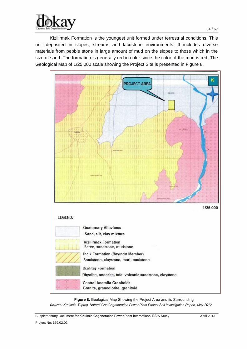
34 / 67 34 / 46
Supplementary Document for Kırıkkale Cogeneration Power Plant International ESIA Study April 2013
Project No: 169.02.02
34 / 52
Kizilirmak Formation is the youngest unit formed under terrestrial conditions. This
unit deposited in slopes, streams and lacustrine environments. It includes diverse
materials from pebble stone in large amount of mud on the slopes to those which in the
size of sand. The formation is generally red in color since the color of the mud is red. The
Geological Map of 1/25.000 scale showing the Project Site is presented in Figure 8.
Figure 8. Geological Map Showing the Project Area and its Surrounding
Source: Kırıkkale-Tüpraş, Natural Gas Cogeneration Power Plant Project Soil Investigation Report, May 2012
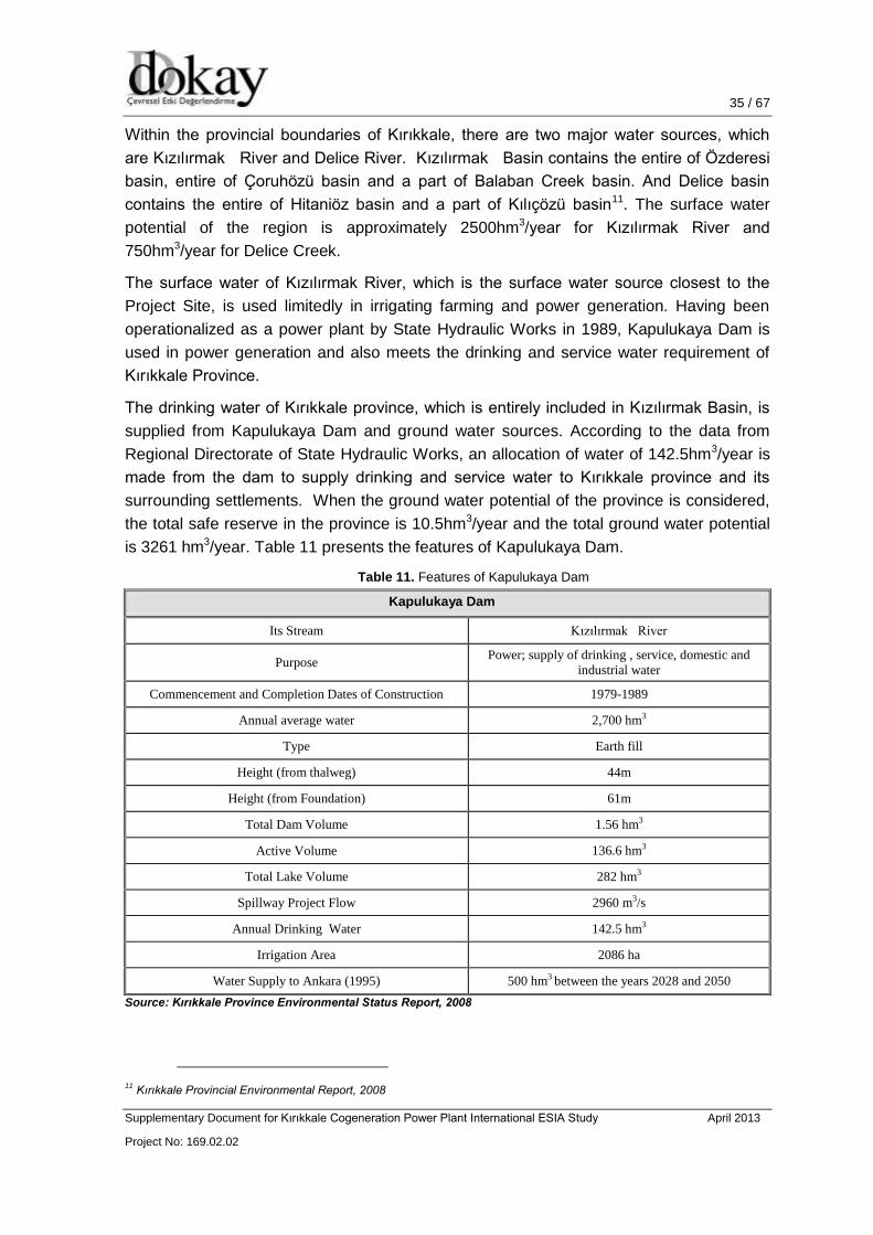
35 / 67 35 / 46
Supplementary Document for Kırıkkale Cogeneration Power Plant International ESIA Study April 2013
Project No: 169.02.02
35 / 52
Within the provincial boundaries of Kırıkkale, there are two major water sources, which
are Kızılırmak River and Delice River. Kızılırmak Basin contains the entire of Özderesi
basin, entire of Çoruhözü basin and a part of Balaban Creek basin. And Delice basin
contains the entire of Hitaniöz basin and a part of Kılıçözü basin11. The surface water
potential of the region is approximately 2500hm3/year for Kızılırmak River and
750hm3/year for Delice Creek.
The surface water of Kızılırmak River, which is the surface water source closest to the
Project Site, is used limitedly in irrigating farming and power generation. Having been
operationalized as a power plant by State Hydraulic Works in 1989, Kapulukaya Dam is
used in power generation and also meets the drinking and service water requirement of
Kırıkkale Province.
The drinking water of Kırıkkale province, which is entirely included in Kızılırmak Basin, is
supplied from Kapulukaya Dam and ground water sources. According to the data from
Regional Directorate of State Hydraulic Works, an allocation of water of 142.5hm3/year is
made from the dam to supply drinking and service water to Kırıkkale province and its
surrounding settlements. When the ground water potential of the province is considered,
the total safe reserve in the province is 10.5hm3/year and the total ground water potential
is 3261 hm3/year. Table 11 presents the features of Kapulukaya Dam.
Table 11. Features of Kapulukaya Dam
Kapulukaya Dam
Its Stream Kızılırmak River
Purpose Power; supply of drinking , service, domestic and
industrial water
Commencement and Completion Dates of Construction 1979-1989
Annual average water 2,700 hm3
Type Earth fill
Height (from thalweg) 44m
Height (from Foundation) 61m
Total Dam Volume 1.56 hm3
Active Volume 136.6 hm3
Total Lake Volume 282 hm3
Spillway Project Flow 2960 m3/s
Annual Drinking Water 142.5 hm3
Irrigation Area 2086 ha
Water Supply to Ankara (1995) 500 hm3 between the years 2028 and 2050
Source: Kırıkkale Province Environmental Status Report, 2008
11
Kırıkkale Provincial Environmental Report, 2008
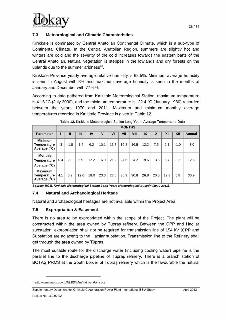
36 / 67 36 / 46
Supplementary Document for Kırıkkale Cogeneration Power Plant International ESIA Study April 2013
Project No: 169.02.02
36 / 52
7.3 Meteorological and Climatic Characteristics
Kırıkkale is dominated by Central Anatolian Continental Climate, which is a sub-type of
Continental Climate. In the Central Anatolian Region, summers are slightly hot and
winters are cold and the severity of the cold increases towards the eastern parts of the
Central Anatolian. Natural vegetation is steppes in the lowlands and dry forests on the
uplands due to the summer aridness12.
Kırıkkale Province yearly average relative humidity is 62.5%. Minimum average humidity
is seen in August with 3% and maximum average humidity is seen in the months of
January and December with 77.6 %.
According to data gathered from Kırıkkale Meteorological Station, maximum temperature
is 41.6 °C (July 2000), and the minimum temperature is -22.4 °C (January 1980) recorded
between the years 1970 and 2011. Maximum and minimum monthly average
temperatures recorded in Kırıkkale Province is given in Table 12.
Table 12. Kırıkkale Meteorological Station Long Years Average Temperature Data
MONTHS
Parameter I II III IV V VI VII VIII IX X XI XII Annual
Minimum Temperature Average (
oC)
-3 -1.8 1.4 6.2 10.1 13.8 16.8 16.5 12.2 7.5 2.1 -1.0 -3.0
Monthly
Temperature
Average (oC)
0.4 2.3 6.9 12.2 16.9 21.2 24.6 24.2 19.6 13.6 6.7 2.2 12.6
Maximum Temperature Average (
oC)
4.1 6.9 12.6 18.0 23.0 27.5 30.9 30.8 26.8 20.5 12.3 5.8 30.9
Source: MGM, Kırıkkale Meteorological Station Long Years Meteorological Bulletin (1970-2011).
7.4 Natural and Archaeological Heritage
Natural and archaeological heritages are not available within the Project Area.
7.5 Expropriation & Easement
There is no area to be expropriated within the scope of the Project. The plant will be
constructed within the area owned by Tüpraş refinery. Between the CPP and Hacılar
substation, expropriation shall not be required for transmission line of 154 kV (CPP and
Substation are adjacent) to the Hacılar substation. Transmission line to the Refinery shall
get through the area owned by Tüpraş.
The most suitable route for the discharge water (including cooling water) pipeline is the
parallel line to the discharge pipeline of Tüpraş refinery. There is a branch station of
BOTAŞ PRMS at the South border of Tüpraş refinery which is the favourable the natural
12
http://www.mgm.gov.tr/FILES/iklim/turkiye_iklimi.pdf

37 / 67 37 / 46
Supplementary Document for Kırıkkale Cogeneration Power Plant International ESIA Study April 2013
Project No: 169.02.02
37 / 52
gas pipeline route. Since the branch station is located within the Refinery area, natural
gas pipeline does not require easement & expropriation.
7.6 Landscaping
After the construction period, landscaping will be carried out around the area with the
species suitable for the climate and vegetation of the region in which the power plant will
be located.
7.7 Land Use
Based on the field survey carried out at the Project Site and its surroundings, the Project
Area is categorized as dry agricultural land.
7.8 Population Characteristics of the Region
According to Turkish Statistical Institute (TÜİK) results of 2012, total population of the
province is 274,727 whereas the total population of Turkey is 75,627,384 and population
density of the province is 61 and population density of the country is 98. As a result, this
number is below the average of Turkey.
According to TÜİK 2011 data, total population of Kırıkkale was 274,992 in 2011, 233,768
of which lived in the city/county centers and 41.224 in towns/villages. In 2011, rural
population rate to the general population was 14.99%, while rural population rate to the
general population was 85.01%. Rate of population of the province to the general
population is above the average in Turkey (76.8%). Distribution of the population by
counties is given in Table 13.
Table 13. Distribution of Population in Kırıkkale by Counties
Counties Province/County Center Town/Villages TOTAL
TOTAL Male Female TOTAL Male Female TOTAL Male Female
Center 193.950 97.411 96.539 8.148 4.224 3.924 202.098 101.635 100.463
Bahşili 5.245 2.628 2.617 1.666 857 809 6.911 3.485 3.426
Balışeyh 2.111 1.059 1.052 4.715 2.427 2.288 6.826 3.486 3.340
Çelebi 782 386 396 1.358 655 703 2.140 1.041 1.099
Delice 2.420 1.304 1.116 7.172 3.467 3.705 9.592 4.771 4.821
Karakeçili 3.115 1.533 1.582 260 124 136 3.375 1.657 1.718
Keskin 10.211 4.975 5.236 9.294 4.766 4.528 19.505 9.741 9.764
Sulakyurt 2.560 1.384 1.176 5.367 2.616 2.751 7.927 4.000 3.927
Yahşihan 13.374 6.202 7.172 3.244 1.648 1.596 16.618 7.850 8.768
TOTAL 233.768 116.882 116.886 41.224 20.784 20.440 274.992 137.666 137.326
Source: TÜİK (Address-based Population Registration System), 2011
7.9 Seismic Activity
Kırıkkale province is located in 1st degree seismic zone. Kırıkkale Province is located in
the tectonic region called as Central Anatolian Plain Region. It is under the influence of

38 / 67 38 / 46
Supplementary Document for Kırıkkale Cogeneration Power Plant International ESIA Study April 2013
Project No: 169.02.02
38 / 52
Ezine Pazarı Fault Zone and the faults associated with it. 1938 M=6.6 Kırşehir-Keskin
Earthquake is the biggest earthquake which affected Kırıkkale in the last century.
At the Project Site, the return period for any two earthquakes having the magnitudes of
5.0 and 6.0 is 7 years and 43 years, respectively. Besides, while the probability of
occurrence of an earthquake having the magnitudes of 6. 0 is 20.6%, the probability of
occurrence of an earthquake having the magnitudes of 6.0 within a period of 50 years
which can be thought as a standard lifecycle has been calculated as 68.5%.
Figure 9. Seismic Map of Kırıkkale
7.10 Soil Characteristics of the Region
The soil in Kırıkkale province generally consists of brown soils. The soil which is brown or
grayish on the surface is small-grained and easily dispersible. It has a rich content of lime.
Its main rock is of volcanic. These soils are accumulated in the alveolar parts in the highly
rugged areas. Exposed volcanic rock surfaces are observed on them. They are fertile
since they are rich in minerals. In addition, there are alluvial soils in the riverside on the
south. They form thick covers in patches. Their slope is slight. They are suitable for field
agriculture and irrigated farming. The fact that the regions dry and receives scare
precipitation is an important factor affecting the soil formation13. Kırıkkale has an
agricultural area of 306,506 ha. 223,040 hectares of which is irrigable. In a 27,907 hectare
part of it (9.1%), irrigational agriculture is done.
13
http://www.kirikkale.gov.tr/index.asp?islem=cografya

39 / 67 39 / 46
Supplementary Document for Kırıkkale Cogeneration Power Plant International ESIA Study April 2013
Project No: 169.02.02
39 / 52
8. ENVIRONMENTAL IMPACTS OF THE PROJECT AND MITIGATION
MEASURES
8.1 Use of Natural Resources
In this section, usage of natural resources such as water (for cooling and
construction/operation activities), fuel, and land within the Project will be discussed.
8.1.1 Land Use
The Project Site of approximately 85000 m2, at an altitude of 705 m, is located adjacent to
the South Eastern corner of the Refinery alongside the existing Hacılar substation. There
is no forest land and Protected Area within the Project Site.
The Project Site is within the Tüpraş Refinery boundary, therefore there is no agricultural
activity within the Project Site.
8.1.2 Fuel Use
The main fuel for the operation of the Project is natural gas. Estimated consumption of the
natural gas is 300,000,000 m3/year.
When natural gas is cut-off or an extraordinary occurrence breaks out and natural gas is
not supplied, diesel oil will be used to meet the requirements in the gas turbine with the
aim of providing electric and steam safety of Tupras. In spite of these measures; if any
problem occurs, heavy fuel oil will be utilized in the auxiliary boiler and the limited amount
of steam will be produced for the procurement of steam required for the safety of Refinery.
Diesel fuel will be used as fuel for the construction equipment and machinery.
8.1.3 Water Use
It has been foreseen that approximately 550 personnel will work in the construction stage
of the project. Based on the assumption in which per capita water consumption will be
18514 L/day-per capita, water need of the personnel will be 101,75 m15 /day-per capita.
The need of drinking water will be met by bottles.
it is assumed that approximately 35 personnel will be employed for the operation stage
and per capita water consumption is 185 L/day, the amount of domestic water which is
required within the scope of the project will be approximately 6,475 m³/day including hand
washing, showers, emergency response cleaning showers, toilets, kitchen and general
cleaning works. The drinking water requirement will be met by the bottles, as in the
construction stage. The reserve water which will be utilized in the cooling system will be
provided from Kapulukaya Dam. Pure (demineralised) water to be stored in the pure water
14
http://tuikapp.tuik.gov.tr/Bolgesel/tabloOlustur.do
15 http://tuikapp.tuik.gov.tr/Bolgesel/tabloOlustur.do

40 / 67 40 / 46
Supplementary Document for Kırıkkale Cogeneration Power Plant International ESIA Study April 2013
Project No: 169.02.02
40 / 52
tank will be primarily used for boiler feed water, chemical solution preparation and
chemical washing.
8.2 Impacts and Mitigation Measures
In this section, the impacts of the project on physical and biologic environment are defined
and legal, administrative and technical measures which will be taken to improve, minimize
and prevent these impacts are separately and elaborately explained.
8.2.1 Wastewater
During the construction, the wastewater will be collected within wastewater tank via
suitable waster system and treated by package treatment system in accordance with the
Water Pollution Control Regulation. The wastewater will be used to prevent the dust which
may occur during the construction activities. The expected amount of wastewater during
the construction stage has been estimated to be 101.75 m3/day. Since the treated water is
used for dust control during construction activities, there will be no discharge of
wastewater during the construction period.
Wastewater management during the operation period will be the industrial wastewater
treatment plant for the wastewater produced from;
Process Water: HRSG blow down water, HRSG drainage water, chemical drainage
water and other operational wastewater.
The blow down water of the cooling tower for the free chlorine control.
Wastewater including oil which is filtered from oil separator.
Wastewater generated from reverse osmosis system to be used in the cooling water
process.
Wastewater used for the cooling system will be discharged to Kızılırmak River.
Seymenoba commits that the effluent from the neutralization treatment plant together with
cooling tower blow-down will comply with the following national limits:
Table 14. Wastewater Discharge Limit Values for the Project
Parameter Unit Composite Sampling 24-hours
COD mg/L 30
TSS mg/L 100
Oil and Grease mg/L 10
Total Phosphorus mg/L -
Total Cyanide mg/L 0.5
Temperature °C 35
pH - 6-9

41 / 67 41 / 46
Supplementary Document for Kırıkkale Cogeneration Power Plant International ESIA Study April 2013
Project No: 169.02.02
41 / 52
Discharge of the cooling water may affect the aquatic ecosystem. Warm water increases
the temperature of the receiving body. This situation causes O2 depletion, therefore
change in the ecological status of the water.
The following waste water streams will be treated on-site before being mixed and
discharged to the river:
Process water effluents including HRSG blowdown, HRSG drain water, chemical
drains and other process waste water will be treated in a neutralization pit;
Cooling tower blowdown shall be treated to control the free chlorine content;
Sewage (domestic/human waste) will be collected in a septic tank and the liquid
effluent mixed with domestic waste water; and
Surface water contaminated with oil that has been passed through an oil / water
separator.
The following waste water streams will be recycled if it is practical to do so:
Surface water shall be collected and transferred to the cooling tower basin.
Condensate return from refinery in a small holding tank prior to testing. If the quality is
acceptable it will be transferred into the steam / water cycle after polishing, otherwise
it will be transferred to the raw water tank or disposed of.
If the above options are not practical, the wastewater streams will be mixed with the other
wastewater streams and discharged to the Kızılırmak River.
During the operation stage of the Project, estimated amount of wastewater will be 2400
m3/day (0.0278 m3/s). According to Kızılırmak monitoring station report of State Hydraulic
Works, annual average flow rate of Kızılırmak River is 74.99 m3/s. On the other hand, as
mentioned above, wastewater discharge to the river is 0.0278 m3/s. According to IFC’s
Guideline on Environmental Wastewater and Ambient Water Quality, discharged cooling
water shall not result in a temperature increase of no more than 3°C at the edge of the
zone where initial mixing and dilution take place. Water balance calculations show that
flow rate of the discharge water is insignificant as compared with the flow rate of the river.
Therefore, temperature of the discharge water will not affect the actual temperature of the
Kızılırmak River due to well mixing and dispersion of the discharged water.
8.2.2 Flora/Fauna
During the operation period of the Project, anthropogenic factors have been expected to
have impact on fauna and flora, therefore on the biological diversity. For this reason;
people who are temporarily or permanently stay within the Project Area will be ensured to
keep the negative impacts on the flora and fauna at the minimum level. The gathering
plant species, the damage on wild animal species, hunting or killing those animals will be
definitely prevented.

42 / 67 42 / 46
Supplementary Document for Kırıkkale Cogeneration Power Plant International ESIA Study April 2013
Project No: 169.02.02
42 / 52
The wastewater will be handled and treated in a suitable way according to discharge limit
values described above.
Moreover; Bern agreement protection measures in regard to the fauna species listed in
Bern Agreement Annex-2 and Annex-3 as well as 6th and 7th articles of the agreement will
be followed in the operation stage of the project.
8.2.3 Noise
The noise to be generated during the operation stage will be resulted from the gas
turbines, steam turbines and air-cooled condensers. The amount of noise reaching to the
nearest receptors will be minimized by the selection of suitable equipment, noise
absorbers and isolation.
8.2.4 Solid Waste
The construction waste will be composed of plates, metal parts, packages and boxes,
iron, steel, cement packages, wood residual and scrap metals. The storage areas which
are assigned for collecting construction waste within short-term will be present in the field.
The construction waste which is recyclable will be recycled and non-recyclable
construction waste will be disposed in accordance with the related regulation.
Recyclable solid waste (glass, paper, plastic, etc.) which will be generated by the
personnel during the construction activities will be collected within separate containers
and given to the licensed recycling companies in accordance with the provisions of
“Regulation on Control of Package Waste”. On the other hand, non-recyclable waste will
be collected within separate containers and disposed in accordance with the provisions of
“Regulation on Control of Solid Waste”.
The amount of excavation soil which will be obtained as a result of excavation to be
performed in the construction stage within the scope of the project has been expected to
be approximately 35,000 m3. The excavation material will be primarily used as filling
material for the plants to be built as well as rehabilitation of the current roads and
environmental planning. Unused part of the excavation waste will be disposed in the
excavation storage area determined by the related municipality in accordance with the
provisions of “Regulation on Control of Excavation Soil, Construction and Debris Waste”.
As the construction activities progress, it has been expected that waste which may be
specified as hazardous waste such as painting boxes, diluting containers, etc. will be
generated. These wastes will be temporarily stored in the waterproof concrete area
separate from other wastes and sent to the plant with waste disposal license for the final
disposal. During the storage and transportation stages; these materials will be disposed in
accordance with the provisions of “Regulation on Control of Hazardous Waste”.
Packaging waste will be generated by the personnel working during the site preparation,
construction, and operation stages of the Project. Recyclable solid waste such as package
material and similar waste which will be generated from the construction works will be
recycled; having signed the protocol with Hacılar Municipality; non-recyclable waste given
43 / 67 43 / 46
Supplementary Document for Kırıkkale Cogeneration Power Plant International ESIA Study April 2013
Project No: 169.02.02
43 / 52
to the solid waste collection system will be disposed. Packaging waste such as paper,
cardboards, etc. which may be recycled will be collected in the containers whose tops are
covered within the construction site separate from the domestic solid waste and then sent
to the licensed recycling companies.
If tyres of vehicles and construction vehicles are required to be changes in the Project
Site, the tyres changes will be delivered to the licensed carriers in accordance with the
provisions of “Regulation on Control of Tyres Which Have Completed Their Life-Cycles”.
Solid waste being generated by FGD unit will be deposited in waste silo temporarily then,
will be sent for the final disposal by a licensed firm. Wasted material will be handled with
the provisions of “Regulation on Control of Hazardous Waste”.
8.2.5 Emission
The manner in which the pollutants which will be released to the atmosphere from the flue
of the proposed plant will spread within the specified construction area (17.5 km in north-
south direction, 17.5 km in east – west direction) under the current meteorological
conditions and the possible level ground concentration (YSK) values generated by the
pollutants in question have been examined with the Air Quality Modelling Study conducted
in September 2012. The modelling study has been conducted including existing thermal
power plant operation and planned CCGT’s normal operational phase and the back-up
phase.
Generally, the source of SO2 emissions in the gas flue is the oxidation of the sulphur
within the fuel. The emission control is performed by either decreasing the sulphur content
of the fuel or increasing SO2 gas. Since natural gas including the sulphur in the negligible
level will be used as main fuel in Kırıkkale Cogeneration Power Plant, SO2 emissions
generated from the plant will be in the negligible level. Since diesel fuel will be used as
reserved fuel, it has been expected that SO2 will be generated under the working
conditions in which diesel fuel is used.
There are two factors causing NOx emissions which will be generated as a result of
combustion process to be performed in the plant. The first one is nitrogen content of the
fuel used for the combustion process. However; more importantly, NOX emission is
generated from the high-temperature oxidation of the nitrogen free in the air. The
generation of NOX is easier when the combustion temperature increases. The boiler
combustion, combustion temperature, pressure etc. are the factors determining the
emissions in question within the plant to be built. The low-NOX burner will be used to
control NOX emissions generated from the planned power plant. NOX will be increased by
decreasing the air rate within specific areas as possible as and fixing the deficient fire.
CO emissions are generated as a result of inefficient combustion. The suitable
persistency period and high-temperature should be ensured to complete the controlled
combustion. The limit value of CO emission is % 15 O2 and 100 mg/Nm3 in the volume.
CO emission to be generated from the flue of the plant will be maximum 100 mg/Nm3.

44 / 67 44 / 46
Supplementary Document for Kırıkkale Cogeneration Power Plant International ESIA Study April 2013
Project No: 169.02.02
44 / 52
Estimated mass flow rates of pollutants running on natural gas and diesel oil are tabulated
below:
Table 15. Mass Flow Rates and Concentrations of Pollutants for Natural Gas Conditions
Parameter Values
NOx
33 mg/Nm³ (dry, %15 O2)
18.12 kg/h (as NO2 )
CO 62 mg/Nm³ (dry, %15 O2)
34,04 kg/h
Table 16. Mass Flow Rates and Concentrations of Pollutants for Diesel Oil Conditions
Parameter
Value1
Gas Turbine Auxiliary Boiler
NOx
33 mg/Nm³ (dry, %15 O2)
18.12 kg/h (as NO2 )
150 mg/Nm³ (dry, %15 O2)
30 kg/h (as NO2 )
CO 62 mg/Nm³ (dry, %15 O2)
34,4 kg/h
80 mg/Nm³ (dry, %15 O2)
16 kg/h
SO2
100 mg/Nm³ (dry, %15 O2)
54,91 kg/h
200 mg/Nm³ (dry, %15 O2)
40 kg/h
* The values are design values of the Project
Guaranteed emission values are given in Section 9.1.
8.2.6 Transmission line and Pipelines
Wastewater discharge pipeline
Appropriate disposal routes for the various aqueous discharges from the Plant are not yet
to be finalized. It is thought that all types of wastewater (after the appropriate treatment
processes) shall be discharged to the Kızılırmak River. Possible impact of the wastewater
discharge to the Kızılırmak River is the thermal pollution. As described in Section 8.2.1,
the flow rate of the wastewater is much lower than the flow rate of the river. Therefore,
cooling water discharge shall not cause thermal pollution in the river hence; aquatic
ecosystem will not be affected.
Transmission line
Since the TEİAŞ substation (Hacılar Substation) is adjacent to the Power Plant,
transmission line to the connection point will not go through any private parcels. Hence,
there won’t be negative impact on the environment. Minimum working distance of 1.11
meters will be applied as per IFC’s Electric Power Transmission and Distribution
Guideline.

45 / 67 45 / 46
Supplementary Document for Kırıkkale Cogeneration Power Plant International ESIA Study April 2013
Project No: 169.02.02
45 / 52
Natural gas supply line
Natural gas will be supplied from the BOTAŞ PRMS station, which is to be constructed
about 1200 meters away from the Project Site, or the branch of the station which is
located at South border of Tüpraş Refinery. Since the branch of the PRMS is within the
borders of the Refinery, this option shall not cause environmental and social negative
impact.

46 / 67 46 / 46
Supplementary Document for Kırıkkale Cogeneration Power Plant International ESIA Study April 2013
Project No: 169.02.02
46 / 52
9. COMPLIANCE WITH BEST AVAILABLE TECHNIQUES (BAT) AND
INDUSTRIAL EMISSIONS DIRECTIVE
The European Council Directive on Industrial Emissions (Integrated Pollution Prevention
and Control) (Directive 2010/75/EU of November 24, 2010) aims at an integrated
approach of pollution prevention and control arising from industrial activities listed in its
Annex I. The Directive requires that “The Commission shall organize an exchange of
information between Member States and the industries on best available techniques,
associated monitoring, and developments in them”. The results of exchange of information
have been published by the Commission as Best Available Techniques reference
documents (BREFs) on each industrial activity listed in Annex I.
To organize the exchange of information the Commission has set up the so called Sevilla
process in order to produce BREFs in all for 33 industrial activities. One of the BREFs is
the BREF on Large Combustion Plants (LCP), which deals with “Combustion installations
with a rated thermal input exceeding 50 MW” according to the IPPC Directive’s Annex I.
This chapter has been developed to determine the Project’s compliance with BAT and
Industrial Emissions Directive. According to IED Article 30 (3), Part 2 of Annex V shall be
applicable for the emissions limit values. IFC EHS Guidelines for Thermal Power Plants
states the emission limit values in its tables 6 (B) and 6 (C). Tables 6,7,8,9 of BREF on
LCPs’ will also be followed. In the following section, comparison of limit values will be
provided. Those limit values will be the guaranteed emission values for the Project.
9.1 Emissions
Emissions to air are one of the most significant risks to the environment presented by the
energy sector and a broad range of substances with the potential to harm the environment
are emitted as a result of combustion activities.
The energy sector is one of the largest contributors to greenhouse gas emissions through
CO2 and to a lesser extent N2O emissions which pose a significant threat to the global
environment.
Emissions to air from combustion installations also have the potential to cause significant
impacts on local air quality. There are a range of emissions and emission sources ranging
from dust from solid fuel and ash storage and handling to NOx, SOx, CO, hydrocarbons,
particulates and heavy metals from combustion plant. All these emissions have the
potential to adversely affect the air quality.
SO2 Emission
Use of FGD System reduces the sulphur oxides which is included in the Project. Following
tables represent the comparison of limit values for different standards.
Steam Boilers consist of independent stacks and each boiler has a thermal input of 95
MWt. Therefore, capacity criteria of 50-100 MWt range has been used for the
determination of limit values. According to
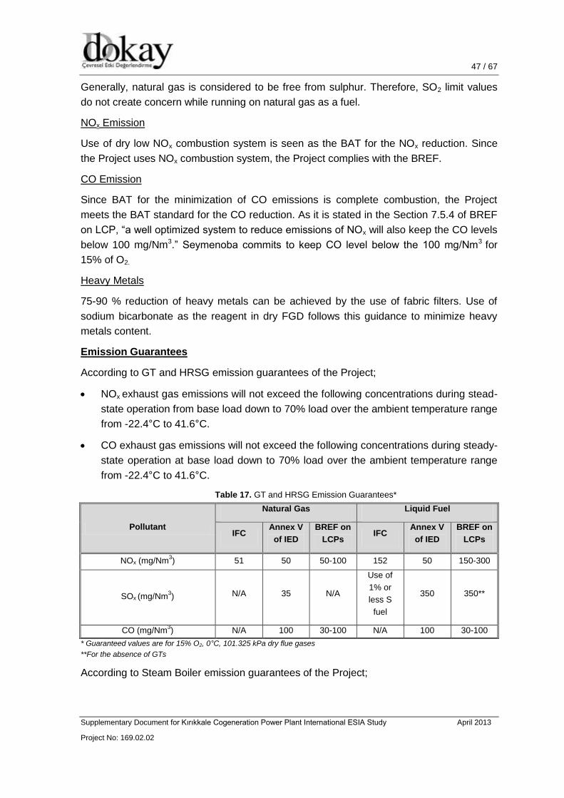
47 / 67 47 / 46
Supplementary Document for Kırıkkale Cogeneration Power Plant International ESIA Study April 2013
Project No: 169.02.02
47 / 52
Generally, natural gas is considered to be free from sulphur. Therefore, SO2 limit values
do not create concern while running on natural gas as a fuel.
NOx Emission
Use of dry low NOx combustion system is seen as the BAT for the NOx reduction. Since
the Project uses NOx combustion system, the Project complies with the BREF.
CO Emission
Since BAT for the minimization of CO emissions is complete combustion, the Project
meets the BAT standard for the CO reduction. As it is stated in the Section 7.5.4 of BREF
on LCP, “a well optimized system to reduce emissions of NOx will also keep the CO levels
below 100 mg/Nm3.” Seymenoba commits to keep CO level below the 100 mg/Nm3 for
15% of O2.
Heavy Metals
75-90 % reduction of heavy metals can be achieved by the use of fabric filters. Use of
sodium bicarbonate as the reagent in dry FGD follows this guidance to minimize heavy
metals content.
Emission Guarantees
According to GT and HRSG emission guarantees of the Project;
NOx exhaust gas emissions will not exceed the following concentrations during stead-
state operation from base load down to 70% load over the ambient temperature range
from -22.4°C to 41.6°C.
CO exhaust gas emissions will not exceed the following concentrations during steady-
state operation at base load down to 70% load over the ambient temperature range
from -22.4°C to 41.6°C.
Table 17. GT and HRSG Emission Guarantees*
Pollutant
Natural Gas Liquid Fuel
IFC Annex V
of IED
BREF on
LCPs IFC
Annex V
of IED
BREF on
LCPs
NOx (mg/Nm3) 51 50 50-100 152 50 150-300
SOx (mg/Nm3) N/A 35 N/A
Use of
1% or
less S
fuel
350 350**
CO (mg/Nm3) N/A 100 30-100 N/A 100 30-100
* Guaranteed values are for 15% O2, 0°C, 101.325 kPa dry flue gases
**For the absence of GTs
According to Steam Boiler emission guarantees of the Project;

48 / 67 48 / 46
Supplementary Document for Kırıkkale Cogeneration Power Plant International ESIA Study April 2013
Project No: 169.02.02
48 / 52
Each steam boiler will not exceed the following concentrations during steady-state
operation from base load down to 50% load over the ambient temperature range from -
22.4°C to 41.6°C.
Table 18. Steam Boilers Emissions Guarantees*
Pollutant
Natural Gas Liquid Fuel
IFC Annex V
of IED
BREF on
LCPs IFC
Annex V
of IED
BREF on
LCPs
NOx (mg/Nm3) 240 100 50-100 400 300 N/A
SOx (mg/Nm3) N/A 35 N/A 900-1500 350 100-350
CO (mg/Nm3) N/A 100 30-100 N/A 80 N/A
* Guaranteed values are for 3% O2, 0°C, 101.325 kPa dry flue gases
9.2 Water Contamination
There are a number of aqueous effluent sources from power generation plant. One of the
most significant effluents is discharge of cooling water, either from once-through cooling
or from cooling tower blowdown. Other effluents include boiler blowdown, effluent from
reverse osmosis plant, waste water from desulphurization plant etc.
According to BREF on LCP, prevention of oil contamination by oil separation wells is a
BAT. Installation of a wastewater treatment plant to remove heavy metal content and to
decrease the amount of solid matter from the water is another BAT.
According to BREF on Industrial Cooling System (ICS), BAT consists of several
approaches such as reduction of water requirements, emissions to water, energy
consumption etc. for the industrial cooling systems.
The Project complies with some of BAT approaches for the reduction of water
requirement such as:
- Optimization of heat reuse; and
- Recirculating systems (cycle amount is 3.28).
For the reduction of entrainment, the Project applies the following BAT approaches:
- Optimization of water velocity with raw water tank to limit sedimentation.
For the reduction of emissions to water, the Project applies a wet cooling tower
against the effect of reduced environmental impact of reduced heat discharge. Aim is
to reduce Delta-T in the Kızılırmak River for each operational season (summer and
winter conditions). The following BAT approaches are also considered for the Project:
- Operating the system for the pH between 7 and 9;
- Closing blowdown temporarily after dosage;
- Monitoring and control of cooling water chemistry;
- Selecting the right material to prevent corrosion;

49 / 67 49 / 46
Supplementary Document for Kırıkkale Cogeneration Power Plant International ESIA Study April 2013
Project No: 169.02.02
49 / 52
- Avoiding stagnant zones in the system;
- Automated cleaning systems; and
- Keeping the water velocity above 0.8 m/s.
After the determination of the water discharge pipeline route, a study on thermal modeling
is recommended.
The liquid effluent from the neutralization treatment plant together with cooling tower
blowdown will be discharged to the River, to follow the recommended pipeline route and
will comply with the following discharge limits:
Table 19. Guaranteed Wastewater Discharge Values
Parameter Unit Composite Sampling 24-hours
COD mg/L 30
TSS mg/L 100
Oil and Grease mg/L 10
Total Phosphorus mg/L -
Total Cyanide mg/L 0.5
Temperature °C 35
pH - 6-9

50 / 67 50 / 46
Supplementary Document for Kırıkkale Cogeneration Power Plant International ESIA Study April 2013
Project No: 169.02.02
50 / 52
10. ADVANTAGES ON THE CURRENT POWER PLANT OF TÜPRAŞ REFINERY
The existing Thermal Power Plant (TPP) in Kırıkkale Refinery is constructed in 1986. TPP
unit has been equipped with two 12 MWe CTR12 type steam turbines and 21 MWe Nuovo
Pignone type steam turbine to meet the Refinery’s electric demand. First and second
turbine has been built in 1986; third one (21MW) has been built in 2007. There are four
120 t/h boilers in Kırıkkale Refinery burning Refinery Gas and Fuel Oil mixture.
According to Tüpraş Refinery emissions monitoring study, following Table 20 and Table
21 are prepared.
Table 20. Features of Power Plant Unit Common Flue
Source F-2201A F-2201B F-2201C F-2201D
Total Thermal
Power MW 211.6
Thermal
Power MW 50.45 52.29 54.43 54.43
Thermal
Power MW 5.62 44.83 4.95 47.34 5.88 48.55 5.88 48.55
Fuel Type Gas Fuel-Oil Gas Fuel-Oil Gas Fuel-Oil Gas Fuel-Oil
Fuel Amount 657.3
Nm3/h
4,100
kg/h
579
Nm3/h
4,330
kg/h
686.6
Nm3/h
4,440
kg/h
686.6
Nm3/h
4,440
kg/h
Efficiency 89.3%
Flue Cross
Section Ø = 2.4 m
Flue Height 120 m

51 / 67 51 / 46
Supplementary Document for Kırıkkale Cogeneration Power Plant International ESIA Study April 2013
Project No: 169.02.02
51 / 52
Table 21. Monitoring Results of Power Plant Unit Common Flue from current operations at the
Refinery
Flue Diameter (m)
2.40
Flue Height
(m)
120
Parameters 1st
Measurement
2nd
Measurement
3rd
Measurement
Average
Gas Temperature (o
C) 131 131 131 131
O2% 13.15 13.13 13.13 13.14
Pressure (atm) 0.933
Humidity (%) 12.9
Flue Gas Velocity (m/s) 16.3
Flue Gas Flow (m3/hour) 265.327
Flue Gas Flow (Under Normal Conditions) (Nm3/hour) 167.280
Flue Gas Flow – Dry Base (Under Normal Conditions) (Nm3/hour) 145.701
Efficiency (%) 89.3 89.3 89.3 89.3
Concentrations (mg/Nm3)
Dust
mg/m3
28.6 30.3 37.4 32.1
mg/Nm3 39.5 41.8 51.6 44.3
3% O2 90.5 95.7 118.1 101.4
Carbon monoxide
(CO)
ppm 1 4 1 2
mg/m3 1 3 1 2
mg/Nm3 1 5 1 3
3% O2 3 11 3 6
Sulfur dioxide (SO2)
ppm 216 218 217 217
mg/m3 389 393 391 391
mg/Nm3 617 623 620 620
3% O2 1415 1425 1418 1419
Nitric oxide
(NO)
ppm 97 101 97 98
mg/m3 88 91 88 89
mg/Nm3 130 135 130 132
3% O2 298 309 297 301
Nitrogen dioxide
(NO2)
ppm 102 106 102 103
mg/m3 142 147 142 143
mg/Nm3 210 218 209 212
3% O2 481 498 479 486
Total Organic Compounds
mg/Nm3
0.856 0.915 0.832 0.868
Mass Flow (kg/hour)
Total Organic Compounds 0.1264
Dust 6.4576
Carbon monoxide
(CO) 0.3643
Sulfur dioxide (SO2) 90.3348
Nitrogen oxides NO 19.1883
NO2 30.9385
52 / 67 52 / 46
Supplementary Document for Kırıkkale Cogeneration Power Plant International ESIA Study April 2013
Project No: 169.02.02
52 / 52
The existing Plant located in Tüpraş refinery has adverse effects from environmental and
economic aspects. Energy efficiency of the current plant is lower than the planned CCGT
system’s efficiency. According to modeling studies, the Project’s emissions (NOx and CO)
are extremely lower than the limit values set forth by Turkish regulations. Natural gas is
used as the main fuel source which is environmentally friendly as compared with other
fuel types. Since the selected system will have back-up fuel; the Project guarantees the
continuity of energy supply to the Refinery in any emergency case, which brings an
advantage compared with the existing plant.

53 / 67 53 / 46
Supplementary Document for Kırıkkale Cogeneration Power Plant International ESIA Study April 2013
Project No: 169.02.02
53 / 52
11. OVERVIEW OF ENVIRONMENTAL AND SOCIAL MANAGEMENT SYSTEM
The ESIA was undertaken between April and November 2012 and conducted by DOKAY
on behalf of AES-Entek. As required in EBRD PR1, the ESIA provides an overview of the
environmental and social baseline at the site, the identification of works that may affect
the baseline and an assessment of the direct and indirect effects of the project. Where
impacts are identified the ESIA has identified mitigation measures that to diminish the
impact of the project on sensitive receptors and resources. The ESIA is considered to be
sufficient for the proposed works and given that construction works at the site are well
advanced it is considered appropriate that any environmental and social gap are
addressed within the ESAP.
The initial compassing stage of the ESIA identified that the following environmental and
social aspects could be out of the scope assessment which include:
Indigenous people;
Land acquisition, involuntary resettlement and economic displacement; and
Cultural heritage
11.1 Occupational Health, Safety, and Environmental Policies of the Project
Owner and the Contractor
Seymenoba Elektrik Uretim A.S and Técnicas Reunidas appointed by AES-Entek as the
turnkey EPC Contractor, apply the procedures established in their HSE Management
Systems in all projects, certified according to:
OHSAS 18001, Occupational Health and Safety Management Systems; and
ISO 14001, Environmental Management Systems.
HSE Policies
Seymenoba commits that everyone, including employees, contractors, visitors and
members of local communities are the first consideration. Seymenoba believes that all
occupational accidents are preventable, and each individual is responsible for their own
safety as well as the safety of their colleagues and other persons affected by their work
activities. Seymenoba is committed to implement its HSE Policy in terms of the following
concerns:
Seymenoba will ensure that adequate resources are allocated and appropriate
responsibilities are identified to meet the requirements of its HSE Policy.
Seymenoba will establish and implement programs, and best practices for conducting
safe, healthful, and environmentally sound operations.
The Project will fully comply with all related Turkish HSE laws and regulations, EBRD
PRs, IFC PS’s, and applicable EU Directives.
What about CEMS and EHS management systems? ISO certification?

54 / 67 54 / 46
Supplementary Document for Kırıkkale Cogeneration Power Plant International ESIA Study April 2013
Project No: 169.02.02
54 / 52
Seymenoba will spend all necessary efforts for the prevention of environmental
pollution, and will seek ways to manage natural resources.
Seymenoba will improve its health, safety, and environmental performance
continuously by setting and reviewing objectives and targets with the required
performance measurements and assessments.
The major element of the HSE Management of the Project is the tracking of all significant
HSE Management actions required to control the Project HSE hazards/risks. Legal
compliance is required to ensure all management actions meet with certain standards.
Construction Permit, Environmental Permit and Independent Control requirements are the
main elements of legal compliance. For the tracking of each action, HSE Compliance
Tracking System (HSE CTS) will be used. This is a database of information on each
action item, which is updated at regular intervals (nominally monthly).
The compliance structure of the Seymenoba HSE Policy with shareholders’ policies,
National and International Requirements during the construction of the Kırıkkale CPP is
shown in Figure 10.
Figure 10. Kırıkkale CPP Construction Stage Health, Safety, and Environmental Management
System Document Structure
Source: Kırıkkale CPP Project HSE Management Plan

55 / 67 55 / 46
Supplementary Document for Kırıkkale Cogeneration Power Plant International ESIA Study April 2013
Project No: 169.02.02
55 / 52
The HSE structure and responsibilities are defined in Kırıkkale CPP Project HSE
Management Plan as follows:
Construction Director – overall responsibility for HSE performance
Site Manager – overall responsibility for HSE performance
HSE Manager – coordination and leadership of HSE management
AES-Entek’s HSE Management applies a procedure for controlling contractors. This
procedure is called “Contractor Selection and Management”. The procedure sets down
the way in which contractors are selected due to HSE qualifications, the HSE
management plans, programs, procedures and resources which must be provided to
support the contracted work, and the methods which are used to control contractors
working within the Project.
Seymenoba commits in the National EIA that waste control/disposal will be conducted
according to National and International requirements. Recyclable materials will be
transported by licensed vehicles to licensed recycling facilities.
Hazardous wastes will be disposed in compliance with related regulations.
A study about area of influence of transmission lines was not conducted during the
National EIA as it will be concern of a separate EIA study. However, as per EBRD and
IFC requirements; influence area and impacts of transmission lines will be covered during
the ESIA studies.
Corporate HSE Policy of Técnicas Reunidas is based on two main principles:
The level of safety and the standards of health and ergonomics can be controlled and achieved.
The adverse environmental impacts of the projects are minimized.
Técnicas Reunidas believes that achievement of such principles will be ensured with a
continuous monitoring of the design along the whole project. HSE issues and actions will
be properly identified and documented.
Técnicas Reunidas ensures that its Quality, Health, Safety, and Environmental Policy is
understood, implemented, continuously updated and communicated at every level of the
Organization. The company commits to:
Foster a continuous improvement in the work methods and procedures, promoting a philosophy of prevention before remedy, “do it right the first time”.
Establish objectives in Quality and HSE and review them periodically.
Satisfy all requirements established by Seymenoba, current legislation and applicable
codes, as well as any further requirements that Seymenoba may choose to endorse.
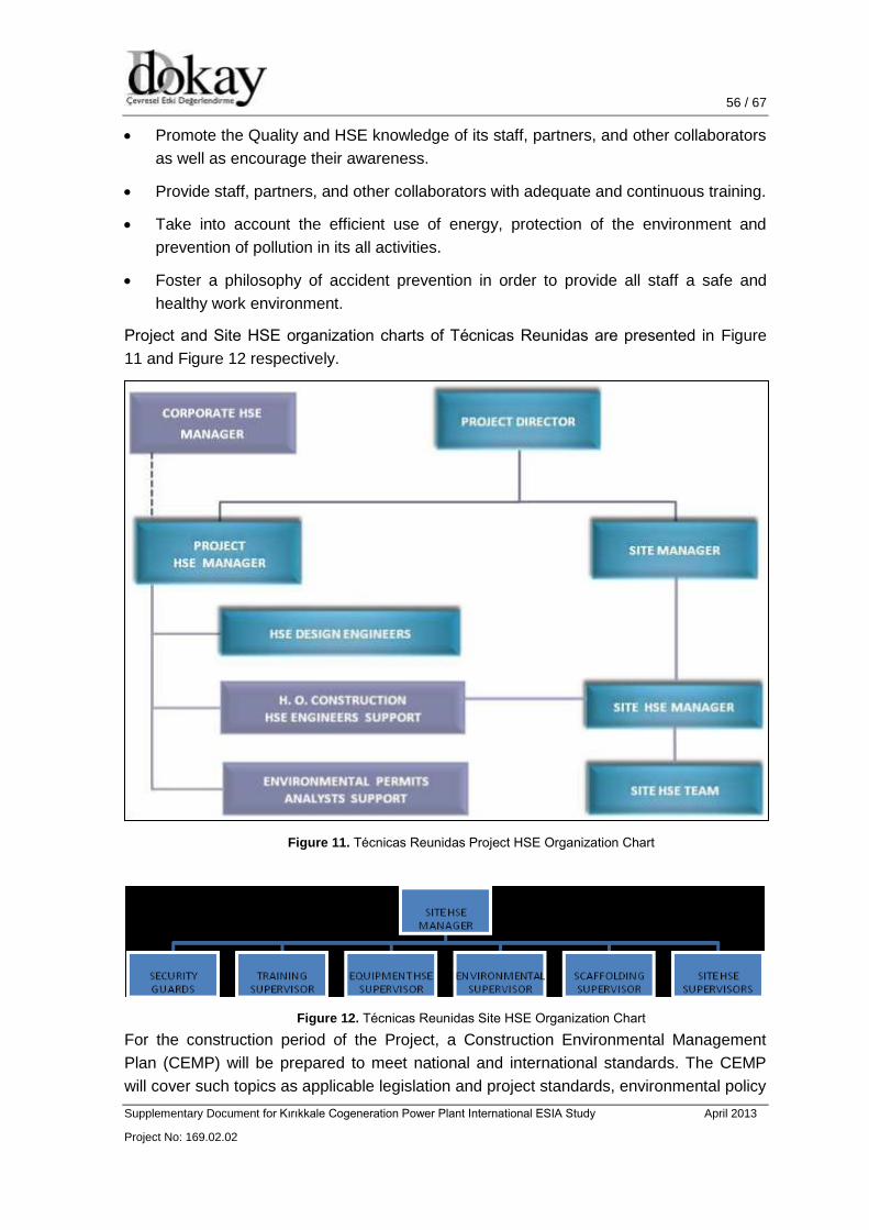
56 / 67 56 / 46
Supplementary Document for Kırıkkale Cogeneration Power Plant International ESIA Study April 2013
Project No: 169.02.02
56 / 52
Promote the Quality and HSE knowledge of its staff, partners, and other collaborators
as well as encourage their awareness.
Provide staff, partners, and other collaborators with adequate and continuous training.
Take into account the efficient use of energy, protection of the environment and
prevention of pollution in its all activities.
Foster a philosophy of accident prevention in order to provide all staff a safe and
healthy work environment.
Project and Site HSE organization charts of Técnicas Reunidas are presented in Figure
11 and Figure 12 respectively.
Figure 11. Técnicas Reunidas Project HSE Organization Chart
Figure 12. Técnicas Reunidas Site HSE Organization Chart
For the construction period of the Project, a Construction Environmental Management
Plan (CEMP) will be prepared to meet national and international standards. The CEMP
will cover such topics as applicable legislation and project standards, environmental policy

57 / 67 57 / 46
Supplementary Document for Kırıkkale Cogeneration Power Plant International ESIA Study April 2013
Project No: 169.02.02
57 / 52
and organization, permit issues, induction and trainings, inspections and reporting as well
as environmental monitoring mechanisms.
11.2 Social Policies of the Project Owner and the Contractor
11.2.1 Grievance Mechanism for Workers
AES-Entek has a “Helpline” for its staff to raise workplace concerns. The details of this
mechanism are presented in Figure 13.

58 / 67 58 / 46
Supplementary Document for Kırıkkale Cogeneration Power Plant International ESIA Study April 2013
Project No: 169.02.02
58 / 52
Figure 13. AES-Entek Helpline
THE HELPLINE
The Helpline is available
– 24 hours a day – 7 days a week – In Turkish
What is it?
AES Entek strives to create a work
environment where AES Entek people feel
free to raise questions or concerns directly
to AES Entek leaders. However, in some
cases AES Entek people may not feel
comfortable doing this. The Helpline offers
another option for AES Entek people to
request advice or report wrongdoing.
All efforts are made to preserve the
confidentiality of the Helpline report.
AES Entek will not tolerate retaliation
against any AES Entek person for raising
questions or making a good faith report of
improper behavior.
Caller may remain anonymous.
How does it work?
– Caller makes a report via the Internet or telephone
– Caller receives a report identification number and is assigned a date to check back on the status of the report
– All reports are tracked in a confidential database
– At the conclusion of the investigation, a final response is delivered to the caller and logged in the database
How to contact the Helpline?
YARDIM HATTI
Yardım Hattı’na
– 7 gün – 24 saat – Türkçe ulaşılabilir.
Yardım Hattı Nedir?
AES Entek, çalışanlarına sorularını
ve kaygılarını amirlerine rahatça
paylaşabilecekleri bir çalışma ortamı
yaratmak için çaba gösterir. Bazı
durumlarda, AES Entek çalışanları
kendilerini bu durumda rahat
hissedemeyebilir. Yardım Hattı, AES Entek
çalışanlarının tavsiye alabilecekleri ve
görevi suistimali bildirebilecekleri başka bir
seçenektir.
Yardım Hattı’na iletilen raporların
gizliliğinin korunması için her türlü önlem
alınmıştır.
Bir ihlali, şüpheli bir davranışı ya da
gerçeğe dayalı bir endişeyi raporlayan bir
çalışana karşı misilleme yapana tölerans
gösterilmeyecektir.
Arayan kişi adını gizleyebilir.
Nasıl çalışır?
– Arayan kişi Internet ya da telefon hattından ulaşabilir
– Arayan kişiye bir kimlik numarası verilir ve raporun durumunu kontrol etmesi için bir tarih verilir
– Bütün raporlar gizli bir veritabında takip edilir
– Soruşturmanın sonunda, arayana nihai karar bildirilir ve sisteme kaydedilir.
Yardım Hattı’na nasıl ulaşılır?
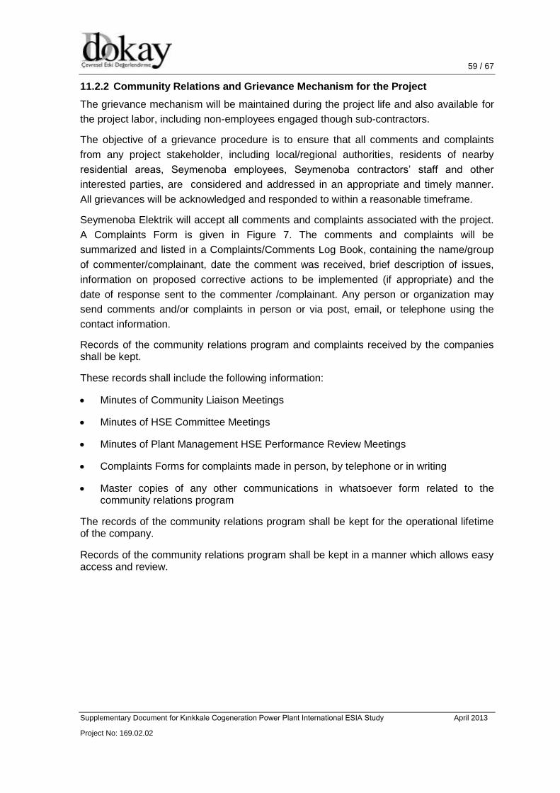
59 / 67 59 / 46
Supplementary Document for Kırıkkale Cogeneration Power Plant International ESIA Study April 2013
Project No: 169.02.02
59 / 52
11.2.2 Community Relations and Grievance Mechanism for the Project
The grievance mechanism will be maintained during the project life and also available for
the project labor, including non-employees engaged though sub-contractors.
The objective of a grievance procedure is to ensure that all comments and complaints
from any project stakeholder, including local/regional authorities, residents of nearby
residential areas, Seymenoba employees, Seymenoba contractors’ staff and other
interested parties, are considered and addressed in an appropriate and timely manner.
All grievances will be acknowledged and responded to within a reasonable timeframe.
Seymenoba Elektrik will accept all comments and complaints associated with the project.
A Complaints Form is given in Figure 7. The comments and complaints will be
summarized and listed in a Complaints/Comments Log Book, containing the name/group
of commenter/complainant, date the comment was received, brief description of issues,
information on proposed corrective actions to be implemented (if appropriate) and the
date of response sent to the commenter /complainant. Any person or organization may
send comments and/or complaints in person or via post, email, or telephone using the
contact information.
Records of the community relations program and complaints received by the companies shall be kept.
These records shall include the following information:
Minutes of Community Liaison Meetings
Minutes of HSE Committee Meetings
Minutes of Plant Management HSE Performance Review Meetings
Complaints Forms for complaints made in person, by telephone or in writing
Master copies of any other communications in whatsoever form related to the community relations program
The records of the community relations program shall be kept for the operational lifetime of the company.
Records of the community relations program shall be kept in a manner which allows easy access and review.

60 / 67 60 / 46
Supplementary Document for Kırıkkale Cogeneration Power Plant International ESIA Study April 2013
Project No: 169.02.02
60 / 52

61 / 67 61 / 46
Supplementary Document for Kırıkkale Cogeneration Power Plant International ESIA Study April 2013
Project No: 169.02.02
61 / 52
Figure 14. Seymenoba Complaint Form
62 / 67 62 / 46
Supplementary Document for Kırıkkale Cogeneration Power Plant International ESIA Study April 2013
Project No: 169.02.02
62 / 52
11.2.3 Health, Safety, and Environment (HSE) Management Plan
This part addresses the overall management plan and system which will used to control
health, safety and environmental (HSE) management and specially applies for the
construction, installation, start-up and commissioning activities of Kırıkkale 233.7 MWe
Natural Gas Fired Cogeneration Plant Construction Project owned by Seymenoba Elektrik
Üretim ve Ticaret A.S.
The purpose of this part is to set down the guiding principles, management structure,
organization and outline of the specific programs which implement Health, Safety and
Environmental (HSE) management within the construction, start up and commissioning
activities at the project.
Construction Director is responsible for ensuring the overall implementation of the HSE
Management Plan and related plans and programs in construction project. Site Manager
is responsible for ensuring the overall implementation of the HSE Management Plan and
related plans and programs on site. HSE Manager is responsible for the design,
organization, management and ensuring the overall implementation of the HSE
Management System and related plans and programs on site. Personnel are responsible
for implementing the HSE Management System, plans, programs and all its individual
components, as part of their general duties and in relation to all work activities which they
carry out.
Seymenoba Elektrik is committed to a high standard of health, safety and environmental
(HSE) management, and throughout the project’s construction and operational process.
This commitment is central to the Company objective of implementing best industry
practices and being a welcome, responsible and long-term member of the local
community. The HSE management system has been developed to provide a framework
by which the Company can effectively manage the HSE issues related to construction,
start up and commissioning activities. The philosophy is that HSE considerations should
be integrated into the day-to-day work activities of the Company, so that good HSE
management becomes a normal, accepted part of work, and is not considered an
additional burden or separate effort divorced from construction. The HSE management
system has been designed in accordance with state-of-the-art, international principles and
practices for the HSE management of power plant constructions, including best industry
practices and the requirements specified for an HSE management system under ISO
14001:2004 – Environmental Management System and OHSAS 18001:1999 -
Occupational Health and Safety Management System promoting continuous improvement
in HSE performance. However the ISO 14001 and OHSAS 18001 Certifications are not
mandatory but a matter of project management’s decision. The HSE management system
follows the “continual improvement” model of PLAN-DO-CHECK-ACT, as shown in Figure
15 below:

63 / 67 63 / 46
Supplementary Document for Kırıkkale Cogeneration Power Plant International ESIA Study April 2013
Project No: 169.02.02
63 / 52
Figure 15. Seymenoba “Continual Improvement” Model of PLAN-DO-CHECK-ACT
The policy stage involves the management commitment to managing health and safety,
environmental issues.
The planning (PLAN) stage involves the hazard identification and risk assessment of the
project and its associated work activities, and the designing of appropriate management
programs by which to control these hazards/risks. The implementation and operation (DO)
stage covers the implementation of controls over construction, start up and commissioning
activities (via written procedures, information/instruction/training to personnel and record-
keeping) to ensure that the hazards/risks are properly managed. The checking and
corrective action (CHECK) stage contains confirmation that control measures are
implemented, via field inspections, walk-downs, reviews, audits, etc. to ensure that what
has been prescribed is actually being executed in the field. Finally, the management
review (ACT) stage includes reviewing the performance of the Company in relation to the
whole HSE management system, and the HSE management system itself as a working
tool, and making any necessary changes to ensure that it continues to be effective and
promotes continuous improvement in performance.
The HSE management system considers all aspects of HSE management, including
organization and roles & responsibilities, communication, physical control of work
activities, work procedures, response to accidents and emergencies, and welfare facilities
for personnel. Part of the HSE management system covers both internal and external
communications, including community relations. Therefore, when implemented fully, the
HSE management system is a comprehensive, complete way of operating safely and
protecting the environment, which is integrated with construction, start up and

64 / 67 64 / 46
Supplementary Document for Kırıkkale Cogeneration Power Plant International ESIA Study April 2013
Project No: 169.02.02
64 / 52
commissioning activities, and makes a significant contribution to the business success of
the Seymenoba Elektrik.
Risk Analysis and Emergency Response Plans including fire, accidents and spills will be prepared for the construction phase of the project. However, general mitigation measures regarding occupational health and safety are:
Employees will be trained for the health and safety requirements;
All the precautions related with working at heights will be taken throughout the
construction and operational phases of the proposed project in accordance with the
EBRD Guidelines and the local regulations;
Material Safety Data Sheets for all chemicals used at the plant will be available at site
and in easy reach to concerned employees;
Proper and approved Personal Protective Equipment (PPE) will be provided to all
employees handling chemicals and will be trained on their use and maintenance;
Key personnel will be trained in first aid and have a valid training certificate;
Employees will be trained on the use of firefighting systems and equipment.
11.2.4 Workers Accommodation and Transportation
During the construction phase, workers will live in a hostel provided by Project Contractor
in city of Kırıkkale or Hacilar District. They will travel to work on a bus-in/bus-out (BIBO)
basis which will be provided by Project Contractor. Workers who are locally resident in
central of Kırıkkale will be transported to the construction site on a daily basis where they
work on a rotational shift basis in common with all other workers. At present, this journey
takes around 30 minutes but might be significantly reduced if bypass route is designated.
The Project Construction Area is managed in accordance with applicable Turkish
standards and the guidance contained in the EBRD Guidance Note “Workers
Accommodation Processes and Standards”. The key elements of the standards are as
follows:
Climatic aspects: given the extreme weather conditions that may occur at site,
accommodation is provided with heating in winter and ventilation or air conditioning in
summer so that the inside temperature is constantly kept around 200C;
Drinking water: is provided in sufficient quantities at all times, either from regular taps
if drinking water quality can be ensured or in bottles;
The following standards apply for accommodation and sanitary facilities:
100 liters of water per worker per day are available in average for personal
hygiene purposes. This water is drinking water quality unless explicitly
marked otherwise;
One hand wash sink per ten persons;
65 / 67 65 / 46
Supplementary Document for Kırıkkale Cogeneration Power Plant International ESIA Study April 2013
Project No: 169.02.02
65 / 52
One toilet per ten persons;
One urinal per fifteen persons.
The construction area is designed to accommodate up to 585 workers, supervisory and
management staff. Construction area is equipped with mess halls, recreational facilities
and medical facilities. The remote construction camps accommodate up to 585 workers
and are sustained by supplies from Hacilar District central onsite facilities. Extinguishers
are provided and fire emergency procedures are in place, with trained fire wardens in the
construction area. All the necessary safety measures will be taken by the Constractor
including emergency exist door, fire alarm system, etc.
11.2.5 Human Resources Policies
AES-Entek has an “Ethical Rules of Conduct and Implementation Principles” document.
The document includes principles and responsibilities of AES-Entek in internal and
external relations as well as ethical rules of conduct to be complied with by employees.
The employees are aware of the document and they are expected to behave accordingly.
In this document, AES-Entek lists its basic principles relating to employee relations as follows:
In recruitment and employment, to seek for certain objective job-related qualifications as the key and single criterion, and to provide and offer equal opportunities;
Employment decisions will not be made on the basis of personal characteristics, such as gender, race nationality, ethnic origin, religion or belief, disability, age or sexual orientation, unrelated to inherent job requirements;
Human resources policies will be maintained appropriate to the workforce;
All workers will receive documentation on their working conditions and terms of employment including their entitlement to wages, hours of work, overtime arrangements and overtime compensation, and any benefits;
To attract to the Company the most qualified and talented young and the most experienced professionals who may take and carry the Company forward;
To make the most of the skills, strengths and creativity of its employees;
To offer equal opportunities for training, guidance and development of its employees in order to let each and every employee to strive for excellence;
To reward the success and achievement through fair and competitive wage policies and effective and objective performance assessment and appraisal systems and practices;
To improve and encourage loyalty of employees to the Company by offering equal opportunities in promotion and rewarding policies;
To preserve and maintain labor peace at all times and try to show each and every employee that the Company could be an ideal place to work;
66 / 67 66 / 46
Supplementary Document for Kırıkkale Cogeneration Power Plant International ESIA Study April 2013
Project No: 169.02.02
66 / 52
To provide the employees with clean, healthy, hygienic and safe working conditions;
To create and maintain a transparent work environment encouraging mutual respect, where the most important components are cooperation solidarity and acting with integrity;
To show not a bit of tolerance to harassment at work;
To welcome, evaluate and respond to comments and suggestions of employees and take motivation increasing actions; and
Not to share with third parties any proprietary information of employees without knowledge of and prior consent of the relevant employee, except for legal obligations.
In its Recruitment Policy, Técnicas Reunidas commits the following:
Técnicas Reunidas carries out their recruitment processes respecting equal opportunities and non-discrimination.
The recruitment processes at Técnicas Reunidas is guided by respect for people, the transparency of information, honesty and professionalism at work.
Técnicas Reunidas guarantees confidentiality of candidates participating in
recruitment processes.

67 / 67 67 / 46
Supplementary Document for Kırıkkale Cogeneration Power Plant International ESIA Study April 2013
Project No: 169.02.02
67 / 52
12. REFERENCES
European Bank for Reconstruction and Development (EBRD). (2008). Environmental
and Social Policy.
European Union (EU). (November 24, 2010). Directive 2010/75/EU of the European
Parliament and of the Council on Industrial Emissions (IPPC).
European Commission (EC) (December 2001). Integrated Pollution Prevention and
Control “Reference Document on the application of Best Available Techniques to
Industrial Cooling Systems”.
European Commission (EC). (July 2006). Integrated Pollution Prevention and Control
“Reference Document on Best Available Techniques for Large Combustion Plants”.
International Finance Corporation (IFC). (2012). Sustainability Framework, Policy and
Performance Standards on Environmental and Social Sustainability Access to
Information Policy.
International Finance Corporation (IFC). (December 19, 2008). Environmental, Health,
and Safety Guidelines for Thermal Power Plants.
International Finance Corporation (IFC). (April 30, 2007). Environmental, Health, and
Safety Guidelines for Electric Power Transmission and Distribution.
International Finance Corporation (IFC). (April 30, 2007). Environmental, Health, and
Safety Guidelines for Environmental Wastewater and Ambient Water Quality.
Seymenoba A.Ş. (2013) Kırıkkale CPP Project HSE Management Plan (Doc. No. SYM-
O-PEP-HSE-00002-R0A).
Técnicas Reunidas. (2012). Kırıkkale CPP Project Technical Proposal-Chapter
22:HSE.