Embed Size (px)
Citation preview

SC I ENCE ROBOT I C S | R E S EARCH ART I C L E
B IOM IMET I CS
John A. Paulson School of Engineering Applied Sciences, Harvard University,Cambridge, MA 02138, USA.*Corresponding author. Email: [email protected]
Rafsanjani et al., Sci. Robot. 3, eaar7555 (2018) 21 February 2018
Copyright © 2018
The Authors, some
rights reserved;
exclusive licensee
American Association
for the Advancement
of Science. No claim
to original U.S.
Government Works
Kirigami skins make a simple soft actuator crawlAhmad Rafsanjani, Yuerou Zhang, Bangyuan Liu, Shmuel M. Rubinstein, Katia Bertoldi*
Bioinspired soft machines made of highly deformable materials are enabling a variety of innovative applications, yettheir locomotion typically requires several actuators that are independently activated. We harnessed kirigami princi-ples to significantly enhance the crawling capability of a soft actuator. We designed highly stretchable kirigamisurfaces in which mechanical instabilities induce a transformation from flat sheets to 3D-textured surfaces akin tothe scaled skin of snakes. First, we showed that this transformation was accompanied by a dramatic change in thefrictional properties of the surfaces. Then, we demonstrated that, when wrapped around an extending soft actuator,the buckling-induced directional frictional properties of these surfaces enabled the system to efficiently crawl.
by guest on March 1, 2018
http://robotics.sciencemag.org/
Dow
nloaded from
INTRODUCTIONNature offers many examples of slender limbless organisms that takeadvantage of both the flexibility of their body and the frictional propertiesof their skin to efficiently move and explore the surrounding space (1–5).For example, snakes rely on the substantial reconfiguration in the shapeof their body (6) andon the frictional anisotropyof their skin (7) topropelthemselves. Not only microscopic features (8, 9) but also the macroscalestructure and arrangement of their ventral scales contribute to such an-isotropic friction (5), because their preferred orientation makes sliding inthe forward direction much easier than in the backward one.
The flexibility of soft-bodied animals has recently inspired the de-sign of new class of soft robots that are easy and inexpensive to fabri-cate yet still can achieve complex motions (10–14). However, efforts toreplicate natural frictional properties in synthetic systems have beenlimited (15, 16). The skin of the vast majority of soft robots consists ofan unstructured flexible membrane that lacks directional frictionalproperties. As a result, multiple actuators activated independentlyare typically required to achieve locomotion (16–21).
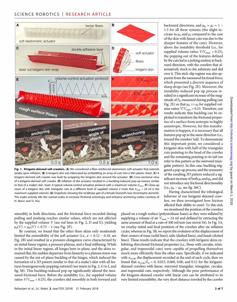
Inspired by the friction-assisted locomotion of snakes (1, 5, 7) and bythe recent advances in engineered surfaces with programmable tribolog-ical behavior (22–25), we introduce here a smart and flexible skin withanisotropic frictional properties that enables a single soft actuator topropelitself. To this end, we took advantage of kirigami, the ancient Japaneseart of paper cutting, whose principles have recently emerged as promisingtools to realize highly stretchable and morphable structures (26–29). Werealized the skin by embedding an array of properly designed cuts into aplanar plastic sheet (Fig. 1A) and then wrapping it around a soft actuator(see Fig. 1, B to D). Upon inflation, the elongation of the actuatortriggered amechanical instability in the kirigami skin that in turn inducedthe pop-up of a three-dimensional (3D) morphology similar to that of asnake’s skin (Fig. 1, E and F). The highly directional 3D features inducedby buckling significantly altered the frictional properties of the kirigamiskins and enabled our simple machine to move forward. The buckling-induced pop-up process observed in our kirigami skin resembles the abil-ity of the snakes to actively actuate their scales (Fig. 1F and movie S1) totune their frictional properties (5).
RESULTSWe considered a soft fluidic actuator comprising an elastomeric tubemade of silicone rubber (Smooth-On Inc., Ecoflex 00-30; shearmodulus
ma≃ 30 kPa)with a length of 164mmand a triangular cross sectionwithedges of 25mm (see Fig. 1, B andC). Tomaximize its elongation duringinflation and constrain any other mode of deformation, we surroundedthe tube with stiff Kevlar fibers arranged in a helical pattern with smallpitch (so that the fibers were almost aligned with the circumferentialdirection—see the Supplementary Materials for details). We found thatthe actuator extended by 25%when inflatedwith amaximumvolume ofVmax = 24 ml of air. However, because symmetry resulted in equalmovements of both actuator ends during inflation and deflation, thissystemdid notmove forwardwhen placed on a substrate (seemovie S2).
Next, we covered the actuator with kirigami skins (see Fig. 1D andmovie S3) and investigated their effect on its ability to move. Ourkirigami skins were fabricated by laser cutting 9 by 32 centimeter-scaleunit cells arranged on a triangular lattice with spacing of l = 4.5 mmand hinge width of d = 0.7 mm into polyester plastic sheets (ArtusCorporation; Young’s modulus of E = 4.33 GPa, see fig. S2). Inspiredby the shapes observed in ventral scales of snakes (22), we consideredfour different cuts (see Fig. 2A): (i) linear cuts, (ii) triangular cuts, (iii)circular cuts, and (iv) trapezoidal cuts. For all assembled kirigami-skinned crawlers, we first characterized their elongation (e) and pres-sure (P) as a function of the supplied volume (V) and then investigatedhow inflation affected the frictional forcewhen theymovedon a substrate.To this end, we pulled (i.e., moved backward) and pushed (i.e., movedforward) the crawlers inflated by different amounts of air against a roughsurface (polyurethane foam) while monitoring the resistive force (Ffr).Effective coefficients of friction in backward (mb) and forward (mf)directions were then extracted from these measurements as
mb ¼Fpeakb
D EFN
; mf ¼Fpeakf
D EFN
ð1Þ
whereFN≃ 0.2N is the crawler’sweight, ⟨ ⋅ ⟩denotes themean value, andFpeakb and Fpeak
f are the local peaks of Ffr recorded during pulling andpushing, respectively (see the Supplementary Materials for details).
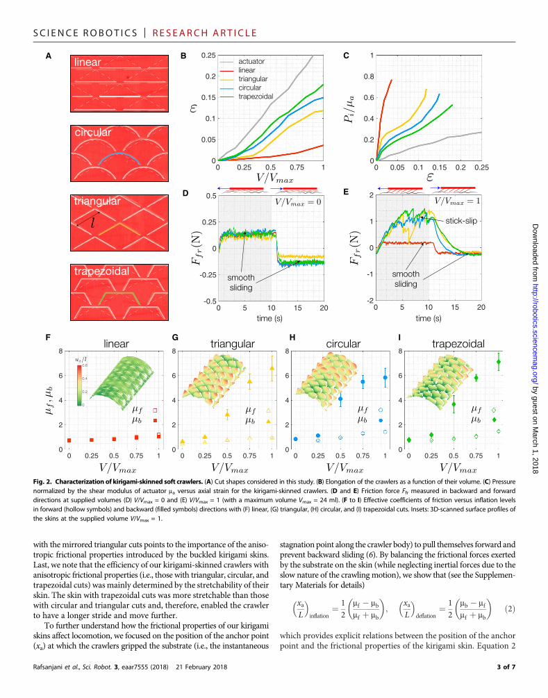
Although the pattern with linear cuts has been used frequently todesign highly stretchable systems (26, 29), we found that thecorresponding kirigami skin severely limited the extensibility of the ac-tuator [i.e., e = (L − L0)/L0 < 0.05, L0, and L denoting the undeformedand deformed lengths of the perforated part of the skin (Fig. 2B)] andmade it very stiff (see Fig. 2C). This is because the antisymmetric out-of-plane buckling mode typical of this kirigami sheet is characterized byalternating up and down (see fig. S6B) buckled ligaments (26) andtherefore is suppressed by the presence of the actuator. Hence, nofeatures pop up upon inflation (see inset in Fig. 2F), the crawler slides
1 of 7
SC I ENCE ROBOT I C S | R E S EARCH ART I C L E
by guest on March 1, 2018
http://robotics.sciencemag.org/
Dow
nloaded from
smoothly in both directions, and the frictional force recorded duringpulling and pushing reaches similar values, which are not affectedby the supplied volume V (see red lines in Fig. 2, D and E), yieldingmf(V) ≃ mb(V) ≃ 0.75 − 1 (see Fig. 2F).
By contrast, we found that the other three skins only moderatelylimited the extensibility of the soft actuator (i.e., e ≃ 0.12 ~ 0.18, seeFig. 2B) and resulted in a pressure-elongation curve characterized byan initial linear regime, a pressure plateau, and a final stiffening.Whilein the initial linear regime, all hinges bent in-plane, and the skins re-mained flat; the sudden departure from linearity to a plateau stress wascaused by the out-of-plane buckling of the hinges, which induced theformation of a 3D pattern similar to that of a snake’s skin with all fea-tures homogeneously popping outward (see insets in Fig. 2, G to I, andfig. S8). This buckling-induced pop-up significantly altered the mea-sured frictional force. Before the instability (i.e., for supplied volumeratios V/Vmax < 0.25), the crawlers slid smoothly in both forward and
Rafsanjani et al., Sci. Robot. 3, eaar7555 (2018) 21 February 2018
backward directions, and mb ≃ mf ≃ 1 ~1.5 for all three systems (the slight in-crease in mb and mf compared to the caseof the skinwith linear cutswas due to thesharper features of the cuts). However,above the instability threshold (i.e., forsupplied volume ratios V/Vmax > 0.25),the popping out of the features definedby the cuts led to a jerkingmotion in back-ward direction, with the crawlers that al-ternatively stuck to the substrate and slidover it. This stick-slip regimewas also ap-parent from themeasured frictional force,which presented a discrete sequence ofsharp drops (see Fig. 2E). Moreover, theinstability-induced pop-up process re-sulted in a significant increase of themag-nitude ofFfrmeasured during pulling (seeFig. 2E) so that mb >> mf for supplied vol-ume ratios V/Vmax > 0.25. Therefore, ourresults indicate that buckling can be ex-ploited to transform the frictional proper-ties of a surface from isotropic to highlyanisotropic. However, for this transfor-mation to happen, it is necessary that allfeatures pop up in the same direction (i.e.,toward the crawlers’ tail). To demonstratethis important point, we considered akirigami skin with half of the triangularcuts pointing to the head of the crawlerand the remaining pointing to its tail (werefer to this pattern as themirrored trian-gular pattern). In this case, buckling trig-gered apop-upprocess, and the symmetryof the resulting 3D pattern induced a sig-nificant increase of bothmf and mb anddidnot introduce any frictional directionality(i.e., mb ~ mf, see fig. S6C).
Having characterized the tribologicalbehavior of our kirigami-skinned craw-lers, we then investigated how frictionaffected their ability to crawl. To this end,wemonitored the position of the crawlers
placed on a rough surface (polyurethane foam) as they were inflated bysupplying a volume of air Vmax = 24 ml and deflated by extracting thesame amount of fluid at a rate of 300ml/min (see movie S4). In Fig. 3A,we overlay initial and final positions of the crawlers after six inflationcycles, whereas in Fig. 3B, we report the evolution of the displacement oftheir centers of mass (solid lines), tails (dashed lines), and heads (dottedlines). These results indicate that the crawlers with kirigami skins ex-hibiting directional frictional properties (i.e., those with circular, trian-gular, and trapezoidal cuts) were capable of propelling themselvesmuch more efficiently than the other ones. Specifically, if we indicatedwith ucycle, the displacement recorded at the end of each cycle, then wefound that ucycle/L0 = 0, 0.015, 0.068, 0.08, and 0.12 for the kirigami-skinned crawlers with linear, mirrored triangular, triangular, circular,and trapezoidal cuts, respectively. Although the poor performance ofthe kirigami-skinned crawler with linear cuts can be attributed to itsvery limited extensibility, the very short distance traveled by the crawler
G
E
A
C
B
D
F
Fig. 1. Kirigami-skinned soft crawlers. (A) We considered a fiber-reinforced elastomeric soft actuator that extendsaxially upon inflation. (B) A kirigami skin was fabricated by embedding an array of cuts into a thin plastic sheet. (C) Akirigami-skinned soft crawler was built by wrapping the kirigami skin around the actuator. (D) Cross-sectional viewof a kirigami-skinned soft crawler. (E) Inflation of the actuator resulted in a buckling-induced pop-up texture similarto that of a snake’s skin. Inset: A typical volume-control actuation protocol with a maximum volume Vmax. (F) Close-upviews of a kirigami skin with triangular cuts at a different level of supplied volume V (note that Vmax = 24 ml is themaximum supplied volume). (G) Snapshots showing the rectilinear gait of a female Dumeril’s boa (Acrantophis dumerili).The snake actively tilts the ventral scales to increase frictional anisotropy and enhance anchoring (video courtesy ofH. Marvi and D. Hu).
2 of 7
SC I ENCE ROBOT I C S | R E S EARCH ART I C L E
by guest on March 1, 2018
http://robotics.sciencemag.org/
Dow
nloaded from
with themirrored triangular cuts points to the importance of the aniso-tropic frictional properties introduced by the buckled kirigami skins.Last, we note that the efficiency of our kirigami-skinned crawlers withanisotropic frictional properties (i.e., those with triangular, circular, andtrapezoidal cuts) wasmainly determined by the stretchability of theirskin. The skin with trapezoidal cuts was more stretchable than thosewith circular and triangular cuts and, therefore, enabled the crawlerto have a longer stride and move further.
To further understand how the frictional properties of our kirigamiskins affect locomotion, we focused on the position of the anchor point(xa) at which the crawlers gripped the substrate (i.e., the instantaneous
Rafsanjani et al., Sci. Robot. 3, eaar7555 (2018) 21 February 2018
stagnation point along the crawler body) to pull themselves forward andprevent backward sliding (6). By balancing the frictional forces exertedby the substrate on the skin (while neglecting inertial forces due to theslow nature of the crawling motion), we show that (see the Supplemen-tary Materials for details)
xaL
� �inflation
¼ 12
mf � mbmf þ mb
� �;
xaL
� �deflation
¼ 12
mb � mfmf þ mb
� �ð2Þ
which provides explicit relations between the position of the anchorpoint and the frictional properties of the kirigami skin. Equation 2
0 5 10 15 20-0.5
-0.25
0
0.25
0.5
0 0.25 0.5 0.75 10
0.05
0.1
0.15
0.2
0.25A B
0 0.25 0.5 0.75 10
2
4
6
8
0 0.25 0.5 0.75 10
2
4
6
8
0 0.25 0.5 0.75 1
2
4
6
8
0 0.25 0.5 0.75 10
2
4
6
8
F
D E
G H I
C
0 0.05 0.1 0.15 0.2 0.250
0.2
0.4
0.6
0.8
1
0 5 10 15 20-2
-1
0
1
2
Fig. 2. Characterization of kirigami-skinned soft crawlers. (A) Cut shapes considered in this study. (B) Elongation of the crawlers as a function of their volume. (C) Pressurenormalized by the shear modulus of actuator ma versus axial strain for the kirigami-skinned crawlers. (D and E) Friction force Ffr measured in backward and forwarddirections at supplied volumes (D) V/Vmax = 0 and (E) V/Vmax = 1 (with a maximum volume Vmax = 24 ml). (F to I) Effective coefficients of friction versus inflation levelsin forward (hollow symbols) and backward (filled symbols) directions with (F) linear, (G) triangular, (H) circular, and (I) trapezoidal cuts. Insets: 3D-scanned surface profiles ofthe skins at the supplied volume V/Vmax = 1.
3 of 7

SC I ENCE ROBOT I C S | R E S EARCH ART I C L E
by guest on March 1, 2018
http://robotics.sciencemag.org/
Dow
nloaded from
indicates that, to maximize the distance traveled by the crawlers, theratio mb/mf should be as large as possible. In this case, xa/L approaches±0.5, and anchoring occurs at the tail during inflation/elongation andat the head during deflation/shortening, completely preventing back-ward sliding. Moreover, Eq. 2 also shows that for mb ~ mf, the anchorpoint is located at the center of mass of the crawlers (i.e., xa/L ~ 0). Inthis case, the head and tail of the crawlers move by the same amount(but in opposite directions) during inflation and deflation, and thereis no advancement. In Fig. 3C, we compared the position of theanchor point extracted by our tests with that predicted by Eq. 2 usingthe experimentally measured friction coefficients reported in Fig. 2(F to I).We found that the trends observed in our experiments are wellcaptured by our simple model. When the kirigami skin has isotropicfrictional properties (as for the patterns with mirrored triangularcuts during the entire inflation/deflation process and with circular,triangular, and trapezoidal cuts before buckling), then xa/L is about 0.By contrast, if mb >> mf (as for the skins with triangular, circular, andtrapezoidal cuts after buckling), then the anchor point moves towardthe tail and the head of the crawler during inflation and deflation,respectively.
The results reported in Fig. 3 (A toC) show that, by taking advantageof the directional frictional properties induced in the kirigami skins by
Rafsanjani et al., Sci. Robot. 3, eaar7555 (2018) 21 February 2018
buckling, even a single soft actuator can propel itself. They also indicatethat the conditions used in our experiments were not optimal, becauseeven for our best kirigami-skinned crawlers, the anchor points werelocated near their centers of mass for volume ratiosV/Vmax < 0.25. Thislimitation can be overcome by not fully deflating the actuators so thatthey always operate in the regionwhere the skin has anisotropic frictionalproperties. In Fig. 3E, we report the measured (markers) and predicted(continuous lines) total displacement (utot) when a total volume Vtot =120 ml of air was supplied by cyclically inflating and deflating them be-tween the maximum volume Vmax = 24 ml and the minimum volumeVmin ∈ [0,Vmax] (see movie S5 and the Supplementary Materials fordetails). We found that there is an optimum value of the minimumvolume Vmin for which the crawlers move more efficiently. Whereasfor smaller values of theminimum volumeVmin, the lack of anisotropicfrictional properties resulted in smaller total displacement utot, whenVmin was increased above the optimum value, the limited change inlength experienced by the crawlers during the cycles became thelimiting factor.
To date, we have considered kirigami skins that were initially flatand in which buckling induced the reversible and repeatable forma-tion of a 3D directional texture, but plastic deformation at the liga-ments can also be harnessed to generate a permanent 3Dmorphology
0 0.25 0.5 0.75 1
2
4
6
8
A B C
D
0 0.25 0.5 0.75 10
0.5
1
0.25
0.75
0 1 2 3 4 5 60
1
E GF
0 0.25 0.5 0.75 10
0.25
0.5
0.75
0
1
0 1 1 3 2 5 3 7 4 9 5
0 0.25 0.5 0.75 1
0.05
0.1
0.15
0.2
0.25
0 1 2 3 4 5 6
0
0.2
0.4
0.6
0.8
1
0 0.5 1 0.5 0-0.5
-0.25
0
0.25
0.5
Fig. 3. Crawler locomotion. (A) Initial and final positionof the crawlers after six inflation cycleswithV∈ [0,24]ml. (B) Displacement of the center ofmass (solid line), head (dashedline), and tail (dotted line) of the crawlers versus number of cycles. (C) Position of the anchor point during inflation and deflation. Themarkers denote the experimental data oversix cycles. The solid lines denote the predictions given by Eq. 2 using the experimentally measured friction coefficients. (D) Measured (markers) and predicted (continuous lines)total displacement when a volume of 120 ml of air was supplied by cyclically inflating and deflating the actuators between Vmax = 24 ml and Vmin ∈ [0,Vmax]. (E) Elongationversus supplied volume for a kirigami-skinned crawler with triangular cuts. Results for elastic (yellow line) and plastically deformed (purple line) skins are compared. The insetshows the plastically deformed skin at V/Vmax = 0 and 1 (with Vmax = 24 ml). (F) Effective coefficients of friction versus supplied volume for the crawler with the plasticallydeformed skin. (G) Measured total displacement for the crawler with the plastically deformed skin when a volume of 120 ml of air was supplied by cyclically inflating anddeflating it between 0 ml and Vpl
max, with Vplmax∈½0;24� ml. Error bars indicate SD of the measured anchor points during six inflation/deflation cycles.
4 of 7

SC I ENCE ROBOT I C S | R E S EARCH ART I C L E
by guhttp://robotics.sciencem
ag.org/D
ownloaded from
(28) and, therefore, to improve the efficiency of the crawlers. To dem-onstrate this, we considered a kirigami skin with triangular cuts, andbefore wrapping it around the actuators, we applied a large stretch sothat in the post-buckling regime, plastic strains developed in the liga-ment between the cuts, creating a permanent pop-up pattern (see insetsof Fig. 3E). We found that this plastically deformed skin affected theresponse of the system in two ways. On the one hand, it increased theelongation that the crawler experienced at the beginning of the infla-tion process (Fig. 3E). On the other hand, its permanent directional tex-ture resulted in highly anisotropic frictional properties through theentire actuation process (Fig. 3F). Hence, the efficiency in locomotionfor this crawler was optimal when the supplied volume was cyclicallyvaried between 0 and 12 ml (Fig. 3G), resulting in ~22% improvementin comparison to the best performance of the corresponding crawlerwith a purely elastic kirigami skin.
est on March 1, 2018
CONCLUSIONIn summary, we have demonstrated that kirigami principles can beexploited to create bioinspired flexible andmorphable skins with direc-tional frictional properties that can be integrated in soft robots toachieve locomotion even with a single extending actuator. Althoughseveral techniques (including rapid prototyping, pop-up fabrication,and origami) have been proposed to fabricate morphable structuresin the recent years, we believe that the proposed kirigami approachprovides a simpler, faster, and cheaper technique to create them. Ourkirigami skins were fabricated by simply embedding an array of cutsinto a planar thin sheet. Mechanical instabilities triggered under uni-axial tension were then exploited to create a 3D pattern and even toguide the formation of permanent folds.
We have shown that the efficiency of our kirigami-skinned crawlerscan be improved by properly balancing the frictional properties andstretchability of the skins through careful choice of the cut geometryand the actuation protocol. Moreover, our results indicate that theplastic deformation at the hinges can be harnessed to further optimizethe response of the system. However, the reversible and repeatable pop-up process observed in the elastic regime offers opportunities for on-demand and active control of friction, which is important for a broadrange of applications, including robotic manipulation and transferprinting (23). Although we have focused on fluid-driven soft actuators
Rafsanjani et al., Sci. Robot. 3, eaar7555 (2018) 21 February 2018
in this study, the designed stretchable kirigami skins can also be appliedto different classes of soft robots, including those based on dielectricelastomers (30, 31), shapememory polymers (32), shapememory alloys(15, 20, 21), and hydrogels (33). In addition, because the properties ofthe designed kirigami skins are primarily governed by the geometry ofthe structure rather than the constitutive properties of the material, theproposed principles can be applied to systems over a wide range oflength scales andmade of differentmaterials. Hence, recent advances intop-down techniques, such as photolithography (26), open up excitingopportunities for miniaturization of the proposed architectures. On theother side, thicker and stiffer sheets can be used to realize skins for largerrobots such as planetary rovers for space exploration.
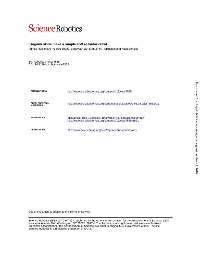
Last, we note that all crawlers considered in this study were actuatedpneumatically using air transferred to them from a stationary source viaa flexible tube. However, real-world applications require systems thatare capable of operating without the constraint of a tether. As a first stepin this direction,we built a fully untetheredkirigami-skinned soft crawlerby integrating on-board control, sensing, actuation, and power supply(Fig. 4A, see the Supplementary Materials for details). Because all thesecomponents can be packed into a volume as small as 25mm3and as lightas 45 g, they can be attached to the tail of the actuator without limitingits ability to move on a variety of terrains (Fig. 4, B and C, movies S6 toS10, and fig. S13). Hence, we believe that our kirigami-based strategyopens avenues for the design of new class of soft crawlers that cantravel across complex environments for search and rescue, explora-tion and inspection operations, environmental monitoring, and med-ical procedures.
MATERIALS AND METHODSFabrication of kirigami-skinned crawlersThe kirigami-skinned soft crawlers investigated in this study compriseda fiber-reinforced soft actuator wrapped with a kirigami sheet. Thefiber-reinforced soft actuators were made by pouring a platinum-catalyzed silicone rubber (Ecoflex 00-30, Smooth-On Inc.) into a 3D-printedmold. The actuator has a hollowprismatic tubewith a triangularcross section. To maximize the elongation of the actuator upon infla-tion and constrain its deformation in the circumferential direction, wesurrounded the elastomeric tube by stiff Kevlar fibers arranged in ahelical pattern. The fibers were held in place by brushing the surface
A B C
Fig. 4. Untethered kirigami-skinned soft crawlers. (A) Fabrication of our untethered kirigami-skinned crawlers. (B) Untethered kirigami-skinned soft crawler withcircular cuts moves over asphalt. (C) Untethered kirigami-skinned soft crawler with trapezoidal cuts climbs a concrete ramp.
5 of 7

SC I ENCE ROBOT I C S | R E S EARCH ART I C L E
of the actuatorwith a very thin layer of uncured elastomer. The kirigamiskins were fabricated by laser cutting an array of 9 by 32 unit cells into51-mmthick polyester plastic sheets (Artus Corporation, NJ). To assemblethe kirigami-skinned crawlers, we wrapped the kirigami sheet aroundthe fiber-reinforced actuator and attached its two edges together using adouble-sided adhesive sheet (Blick Art Materials, IL). More details oncrawler design, geometry of cuts, fabrication, testingmethods, analyticalmodel, and finite-element simulationsmay be found in the SupplementaryMaterials.
by guest on March
http://robotics.sciencemag.org/
Dow
nloaded from
SUPPLEMENTARY MATERIALSrobotics.sciencemag.org/cgi/content/full/3/15/eaar7555/DC1Supplementary sections S1 to S4.Fig. S1. Fabrication of an extending fiber-reinforced actuator.Fig. S2. Kirigami patterns.Fig. S3. Fabrication and assembly of kirigami-skinned crawlers.Fig. S4. Untethered kirigami-skinned crawler.Fig. S5. Mechanical response of the actuator.Fig. S6. Mechanical response of kirigami sheets.Fig. S7. Mechanical response of kirigami-skinned crawlers.Fig. S8. Evolution of surface morphology for our kirigami-skinned crawlers.Fig. S9. Friction measurement setup.Fig. S10. Friction measurements.Fig. S11. Effective friction coefficients.Fig. S12. Frictional properties of a crawler with a plastically deformed skin.Fig. S13. Locomotion of our untethered kirigami-skinned crawler.Fig. S14. Relation between the location of the anchor point and the fraction coefficients.Fig. S15. Finite-element simulations of kirigami unit cells.Movie S1. Rectilinear gait of a female Dumeril’s boa.Movie S2. A fiber-reinforced extending actuator is placed over a rough surface and issubjected to cyclic inflation/deflation.Movie S3. Assembly of a kirigami-skinned soft crawler.Movie S4. Motion of the crawlers during six inflation cycles with V ∈ [0,24] ml.Movie S5. Motion of the crawlers when a total volume Vtot = 120 ml of air is supplied bycyclically inflating and deflating them between Vmax = 24 ml and Vmin ∈ [0,Vmax].Movie S6. Fully untethered kirigami skinned crawlers with triangular, circular, and trapezoidalkirigami skins.Movie S7. An untethered crawler with circular kirigami skin propels itself over asphalt.Movie S8. An untethered crawler with trapezoidal kirigami skin climbs a concrete ramp.Movie S9. An untethered crawler with triangular kirigami skin propels itself over rough stone.Movie S10. Motion of an untethered crawler with trapezoidal kirigami skin for Pmin = 1, 4, 8,and 12 kPa and Pmax = 16 kPa.References (34–38)
1, 2018
REFERENCES AND NOTES1. H. W. Lissmann, Rectilinear locomotion in a snake (Boa occidentalis). J. Exp. Biol. 26,
368–379 (1950).
2. M. Denny, Locomotion: The cost of gastropod crawling. Science 208, 1288–1290(1980).
3. D. Berrigan, D. J. Pepin, How maggots move: Allometry and kinematics of crawling inlarval Diptera. J. Insect Physiol. 41, 329–337 (1995).
4. R. D. Maladen, Y. Ding, C. Li, D. I. Goldman, Undulatory swimming in sand: Subsurfacelocomotion of the sandfish lizard. Science 325, 314–318 (2009).
5. H. Marvi, J. P. Cook, J. L. Streator, D. L. Hu, Snakes move their scales to increase friction.Biotribology 5, 52–60 (2016).
6. R. M. Alexander, Principles of Animal Locomotion (Princeton Univ. Press, 2006).
7. D. L. Hu, J. Nirody, T. Scott, M. J. Shelley, The mechanics of slithering locomotion.Proc. Natl. Acad. Sci. U.S.A. 106, 10081–10085 (2009).
8. J. Hazel, M. Stone, M. S. Grace, V. V. Tsukruk, Nanoscale design of snake skin for reptationlocomotions via friction anisotropy. J. Biomech. 32, 477–484 (1999).
9. R. A. Berthé, G. Westhoff, H. Bleckmann, S. N. Gorb, Surface structure and frictionalproperties of the skin of the Amazon tree boa Corallus hortulanus (Squamata, Boidae).J. Comp. Physiol. A 195, 311–318 (2009).
10. D. Trivedi, C. D. Rahn, W. M. Kier, I. D. Walker, Soft robotics: Biological inspiration, state ofthe art, and future research. Appl. Bionics Biomech. 5, 99–117 (2008).
Rafsanjani et al., Sci. Robot. 3, eaar7555 (2018) 21 February 2018
11. C. Majidi, Soft Robotics: A perspective–current trends and prospects for the future.Soft Robotics 1, 5–11 (2013).
12. S. Kim, C. Laschi, B. Trimmer, Soft robotics: A bioinspired evolution in robotics.Trends Biotechnol. 31, 287–294 (2013).
13. D. Rus, M. T. Tolley, Design, fabrication and control of soft robots. Nature 521, 467–475(2015).
14. N. W. Pikul, S. Li, H. Bai, R. T. Hanlon, I. Cohen, R. F. Shepherd, Stretchable surfaces withprogrammable 3D texture morphing for synthetic camouflaging skins. Science 358,210–214 (2017).
15. A. Menciassi, D. Accoto, S. Gorini, P. Dario, Development of a biomimetic miniaturerobotic crawler. Auton. Robotics 21, 155–163 (2006).
16. J. Z. Ge, A. A. Calderón, N. O. Pérez-Arancibia, An earthworm-inspired soft crawling robotcontrolled by friction. arXiv 1707.04084 (2017).
17. K. Suzumori, T. Hama, T. Kanda, New pneumatic rubber actuators to assist colonoscopeinsertion, in IEEE International Conference on Robotics and Automation, (ICRA, 2006),pp. 1824–1829.
18. R. F. Shepherd, F. Ilievski, W. Choi, S. A. Morin, A. A. Stokes, A. D. Mazzeo, X. Chen,M. Wang,G. M. Whitesides, Multigait soft robot. Proc. Natl. Acad. Sci. U.S.A. 108,20400–20403 (2011).
19. F. Connolly, P. Polygerinos, C. J. Walsh, K. Bertoldi, Mechanical programming of softactuators by varying fiber angle. Soft Robotics 2, 26–32 (2015).
20. S. Seok, C. Denizel Onal, K.-J. Cho, R. J. Wood, D. Rus, S. Kim, Meshworm: A peristaltic softrobot with antagonistic nickel titanium coil actuators. IEEE/ASME Trans. Mechatronics 18,1485–1497 (2013).
21. T. Umedachi, V. Vikas, B. A. Trimmer, Softworms: The design and control of non-pneumatic, 3D-printed, deformable robots. Bioinspir. Biomim. 11, 025001 (2016).
22. H. A. Abdel-Aal, M. El Mansori, Tribological analysis of the ventral scale structure in aPython regius in relation to laser textured surfaces. Surf. Topogr. Metrol. Prop. 1, 015001(2013).
23. H. Marvi, Y. Han, M. Sitti, Actively controlled fibrillar friction surfaces. Appl. Phys. Lett. 106,051602 (2015).
24. S. Das, N. Cadirov, S. Chary, Y. Kaufman, J. Hogan, K. L. Turner, J. N. Israelachvili, Stick–slipfriction of gecko-mimetic flaps on smooth and rough surfaces. J. R. Soc. Interface 12,20141346 (2015).
25. T. Yamaguchi, Y. Sawae, S. M. Rubinstein, Effects of loading angles on stick–slip dynamicsof soft sliders. Extreme Mech. Lett. 9, 331–335 (2016).
26. T. C. Shyu, P. F. Damasceno, P. M. Dodd, A. Lamoureux, L. Xu, M. Shlian, M. Shtein,S. C. Glotzer, N. A. Kotov, A kirigami approach to engineering elasticity innanocomposites through patterned defects. Nat. Mater. 14, 785–789 (2015).
27. M. K. Blees, A. W. Barnard, P. A. Rose, S. P. Roberts, K. L. McGill, P. Y. Huang, A. R. Ruyack,J. W. Kevek, B. Kobrin, D. A. Muller, P. L. McEuen, Graphene kirigami. Nature 524, 204–207(2015).
28. A. Rafsanjani, K. Bertoldi, Buckling-induced kirigami. Phys. Rev. Lett. 118, 084301 (2017).29. Y. Tang, G. Lin, S. Yang, Y. K. Yi, R. D. Kamien, J. Yin, Programmable kiri-kirigami
metamaterials. Adv. Mater. 29, 1604262 (2017).30. S. Shian, K. Bertoldi, D. R. Clarke, Dielectric elastomer based “grippers” for soft robotics.
Adv. Mater. 27, 6814–6819 (2015).31. T. Li, G. Li, Y. Liang, T. Cheng, J. Dai, X. Yang, B. Liu, Z. Zeng, Z. Huang, Y. Luo, T. Xie,
W. Yang, Fast-moving soft electronic fish. Sci. Adv. 3, e1602045 (2017).32. A. Miriyev, K. Stack, H. Lipson, Soft material for soft actuators. Nat. Commun. 8, 596
(2017).33. H. Yuk, S. Lin, C. Ma, M. Takaffoli, N. X. Fang, X. Zhao, Hydraulic hydrogel actuators and
robots optically and sonically camouflaged in water. Nat. Commun. 8, 14230 (2017).34. B. C. Jayne, S. J. Newman, M. M. Zentkovich, H. M. Berns, Why arboreal snakes should not
be cylindrical: Body shape, incline and surface roughness have interactive effects onlocomotion. J. Exp. Biol. 218, 3978–3986 (2015).
35. F. Connolly, C. J. Walsh, K. Bertoldi, Automatic design of fiber-reinforced soft actuators fortrajectory matching. Proc. Natl. Acad. Sci. U.S.A. 114, 51–56 (2017).
36. A. Lamoureux, K. Lee, M. Shlian, S. R. Forrest, M. Shtein, Dynamic kirigami structures forintegrated solar tracking. Nat. Commun. 6, 8092 (2015).
37. M Isobe, K. Okumura, Initial rigid response and softening transition of highly stretchablekirigami sheet materials. Sci. Rep. 6, 24758 (2016).
38. M. Senn, C. Eberl, Digital Image Correlation and Tracking (2015); https://uk.mathworks.com/matlabcentral/fileexchange/50994-digital-imagecorrelation-and-tracking.
AcknowledgmentsFunding: Research was supported by the NSF under grant number DMR-1420570.A.R. acknowledges the financial support provided by the Swiss National Science Foundationunder grant number P300P2-164648. Author contributions: A.R. and K.B. conceived theconcepts and designed the research. A.R., Y.Z., and B.L. built the crawlers and performed theexperiments. B.L. developed the control unit for the untethered crawler. A.R. and S.M.Rdeveloped the theoretical model. A.R., S.M.R., and K.B. analyzed the data and wrote the paper.
6 of 7

SC I ENCE ROBOT I C S | R E S EARCH ART I C L E
K.B. supervised the research. Competing interests: A.R. and K.B. are named inventors on U.S.Provisional Patent Application No. 62,624,371, which has been submitted by President andFellows of Harvard College and generally covers transformation of a 2D sheet into a3D-patterned, perforated surface, such as a kirigami structure induced by buckling ofinterconnecting ligaments. The other authors declare no competing interests. Data andmaterials availability: All data needed to support the conclusions are in the main text or theSupplementary Materials.
Rafsanjani et al., Sci. Robot. 3, eaar7555 (2018) 21 February 2018
Submitted 13 December 2017Accepted 2 February 2018Published 21 February 201810.1126/scirobotics.aar7555
Citation: A. Rafsanjani, Y. Zhang, B. Liu, S. M. Rubinstein, K. Bertoldi, Kirigami skins make asimple soft actuator crawl. Sci. Robot. 3, eaar7555 (2018).
7 of 7
by guest on March 1, 2018
http://robotics.sciencemag.org/
Dow
nloaded from
Kirigami skins make a simple soft actuator crawlAhmad Rafsanjani, Yuerou Zhang, Bangyuan Liu, Shmuel M. Rubinstein and Katia Bertoldi
DOI: 10.1126/scirobotics.aar7555, eaar7555.3Sci. Robotics
ARTICLE TOOLS http://robotics.sciencemag.org/content/3/15/eaar7555
MATERIALSSUPPLEMENTARY http://robotics.sciencemag.org/content/suppl/2018/02/16/3.15.eaar7555.DC1
REFERENCES
http://robotics.sciencemag.org/content/3/15/eaar7555#BIBLThis article cites 34 articles, 10 of which you can access for free
PERMISSIONS http://www.sciencemag.org/help/reprints-and-permissions
Terms of ServiceUse of this article is subject to the
is a registered trademark of AAAS.Science RoboticsAmerican Association for the Advancement of Science. No claim to original U.S. Government Works. The title New York Avenue NW, Washington, DC 20005. 2017 © The Authors, some rights reserved; exclusive licensee
(ISSN 2470-9476) is published by the American Association for the Advancement of Science, 1200Science Robotics
by guest on March 1, 2018
http://robotics.sciencemag.org/
Dow
nloaded from

Supplementary Materials for
Kirigami skins make a simple soft actuator crawl
Ahmad Rafsanjani, Yuerou Zhang, Bangyuan Liu, Shmuel M. Rubinstein,
Katia Bertoldi*
*Corresponding author. Email: [email protected]
Published 21 February 2018, Sci. Robot. 3, eaar7555 (2018)
DOI: 10.1126/scirobotics.aar7555
The PDF file includes:
Supplementary sections S1 to S4.
Fig. S1. Fabrication of an extending fiber-reinforced actuator.
Fig. S2. Kirigami patterns.
Fig. S3. Fabrication and assembly of kirigami-skinned crawlers.
Fig. S4. Untethered kirigami-skinned crawler.
Fig. S5. Mechanical response of the actuator.
Fig. S6. Mechanical response of kirigami sheets.
Fig. S7. Mechanical response of kirigami-skinned crawlers.
Fig. S8. Evolution of surface morphology for our kirigami-skinned crawlers.
Fig. S9. Friction measurement setup.
Fig. S10. Friction measurements.
Fig. S11. Effective friction coefficients.
Fig. S12. Frictional properties of a crawler with a plastically deformed skin.
Fig. S13. Locomotion of our untethered kirigami-skinned crawler.
Fig. S14. Relation between the location of the anchor point and the fraction
coefficients.
Fig. S15. Finite-element simulations of kirigami unit cells.
Legends for movies S1 to S10
References (34–38)
Other Supplementary Material for this manuscript includes the following:
(available at robotics.sciencemag.org/cgi/content/full/3/15/eaar7555/DC1)
Movie S1 (.mp4 format). Rectilinear gait of a female Dumeril’s boa.
robotics.sciencemag.org/cgi/content/full/3/15/eaar7555/DC1

Movie S2 (.mp4 format). A fiber-reinforced extending actuator is placed over a
rough surface and is subjected to cyclic inflation/deflation.
Movie S3 (.mp4 format). Assembly of a kirigami-skinned soft crawler.
Movie S4 (.mp4 format). Motion of the crawlers during six inflation cycles with V
∈ [0,24] ml.
Movie S5 (.mp4 format). Motion of the crawlers when a total volume Vtot = 120
ml of air is supplied by cyclically inflating and deflating them between Vmax = 24
ml and Vmin ∈ [0,Vmax].
Movie S6 (.mp4 format). Fully untethered kirigami skinned crawlers with
triangular, circular, and trapezoidal kirigami skins.
Movie S7 (.mp4 format). An untethered crawler with circular kirigami skin
propels itself over asphalt.
Movie S8 (.mp4 format). An untethered crawler with trapezoidal kirigami skin
climbs a concrete ramp.
Movie S9 (.mp4 format). An untethered crawler with triangular kirigami skin
propels itself over rough stone.
Movie S10 (.mp4 format). Motion of an untethered crawler with trapezoidal
kirigami skin for Pmin = 1, 4, 8, and 12 kPa and Pmax = 16 kPa.
Supplementary sections S1 to S4.
S1 Fabrication The kirigami-skinned soft crawlers investigated in this study comprise a fiber-reinforced soft
actuator with a kirigami sheet wrapped around. In this Section, we describe our methods for
fabricating both the fiber-reinforced soft actuators and the kirigami sheets as well as for
assembling the kirigami-skinned crawlers.
Fiber-reinforced soft actuators
The fiber-reinforced soft actuators considered in this study are made of platinum-catalyzed
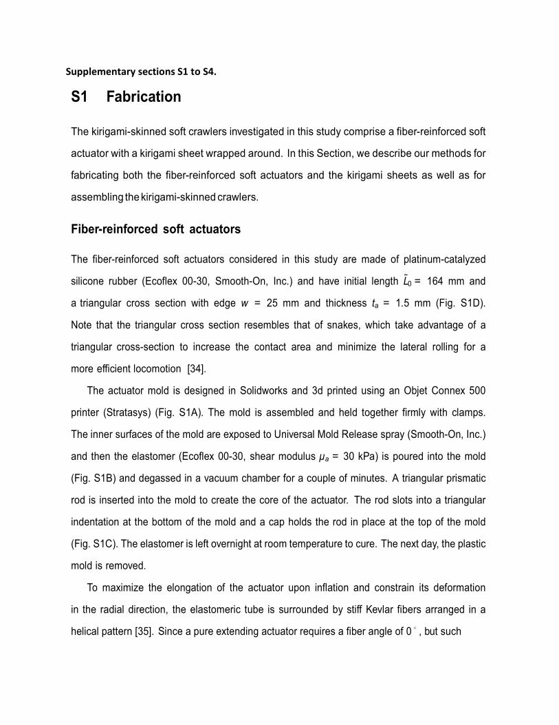
silicone rubber (Ecoflex 00-30, Smooth-On, Inc.) and have initial length L0 = 164 mm and
a triangular cross section with edge w = 25 mm and thickness ta = 1.5 mm (Fig. S1D).
Note that the triangular cross section resembles that of snakes, which take advantage of a
triangular cross-section to increase the contact area and minimize the lateral rolling for a
more efficient locomotion [34].
The actuator mold is designed in Solidworks and 3d printed using an Objet Connex 500
printer (Stratasys) (Fig. S1A). The mold is assembled and held together firmly with clamps.
The inner surfaces of the mold are exposed to Universal Mold Release spray (Smooth-On, Inc.)
and then the elastomer (Ecoflex 00-30, shear modulus µa = 30 kPa) is poured into the mold
(Fig. S1B) and degassed in a vacuum chamber for a couple of minutes. A triangular prismatic
rod is inserted into the mold to create the core of the actuator. The rod slots into a triangular
indentation at the bottom of the mold and a cap holds the rod in place at the top of the mold
(Fig. S1C). The elastomer is left overnight at room temperature to cure. The next day, the plastic
mold is removed.
To maximize the elongation of the actuator upon inflation and constrain its deformation
in the radial direction, the elastomeric tube is surrounded by stiff Kevlar fibers arranged in a
helical pattern [35]. Since a pure extending actuator requires a fiber angle of 0◦ , but such

Figure S1. Fabrication of an extending fiber-reinforced actuator. (A) Exploded view of the 3D printed mold showing the indent in the rear cap and the path for fibers. (B) The elastomer is poured into the mold. (C) The rod is inserted into the mold and held in place by the caps. (D) Picture of the fabricated fiber-reinforced actuator.
angle is difficult to achieve in practice, we use two families of fibers arranged
symmetrically at a characteristic angle α1 ≃ 7◦ and α2 ≃ 7◦ (Fig. S1D). This leads to an
actuator that purely extend and does not twist and expand. To control the fiber angle during
fabrication, ridges are introduced on the surface of the mold. These leave grooves on the
actuator, which define the path for winding the fibers. At each end of the actuator the fiber is
looped around a few times and tied. The fibers and knots are held in place by brushing the
surface of the actuator with a very thin layer of uncured elastomer. The actuator is then
carefully removed from the rod. The ends of the actuator are plugged with Sil-Poxy, and a
vented screw is inserted at one end. The Sil-Poxy is allowed to cure for 24 hours.
A B C
fiber path
indent
middle rod
Kevlar fibers
D

Kirigami sheets
The kirigami sheets are fabricated by laser cutting an array of 9 × 32 cuts into polyester plastic
sheets (Artus Corporation, NJ) with Youngs modulus E = 4.33 GPa and Poissons ratio ν = 0.4.
Figure S2. Kirigami patterns. (A) Unit cell and points used to generate different cut shapes. (B)-(E) Four different cut shapes are considered in this study: (B) linear cuts, (C) triangular cuts, (D) circular cuts and (E) trapezoidal cuts. (F) We also consider a mirrored pattern based on triangular cuts.The repeating units are high- lighted in each graph. (G) Kirigami skeets fabricated by laser cutting a polyester plastic sheet.
A
linear triangular
circular trapezoidal
B C
D E
F mirrored
G

In all our designs the cuts are arranged on a triangular lattice with unit cell defined by the
primitive vectors a1 = [l cos π/6, l sin π/6] and a2 = [l cos π/6, l sin π/6] (Fig. S2A). Each
unit cell comprises a cut with end points P1 = a1δ/l and P5 = a1 + a2(1 δ/l) (Fig. S2A). In
this study we consider four different cut shapes:
• Linear cuts: these consists of horizontal straight cuts that connect the points P1 and P5
and define an array of hinges with minimum width δ0 = 2δ cos π/6 (Fig. S2B). Note
that the response of kirigami sheets with such perforation pattern has been investigated in
several studies [30, 31, 36, 37].
• Triangular cuts: these consists of two straight cuts connecting the points P1, P3 = a1
and P5 and define an array of hinges with minimum width δ0 = δ cos π/6 (Fig. S2C).
• Circular cuts: these consists of circular segments with end points P1 and P5 and radius
r = l δ and define an array of hinges with minimum width 2 20 1l l
(Fig. S2D).
• Trapezoidal cuts: these consists of three straight cuts connecting the points P1, P2
= a1 [(l δ) tan π/6, 0], P4 = a1 + [(l δ) tan π/6, 0] and P5 and define an array
of hinges with minimum width δ0 = δ sin π/6 (Figure S2E). All fabricated kirigami sheets are characterized by δ/l = 0.156, with l = 4.5 mm.
Finally, to investigate the effect of the asymmetry of the kirigami patterns on the motion of
the crawlers, we also consider a mirrored triangular pattern comprising triangular cuts that point
both upward and downward (Fig. S2F). The repeating unit of the mirrored design is defined by
the primitive vectors a1 = [2lcos π/6, 0] and a2 = [0, 16lsin π/6].

Assembly of the kirigami-skinned crawlers To assemble the kirigami-skinned crawlers, we wrap the kirigami sheet around the fiber-reinforced
actuator. To this end, we use a double-sided adhesive sheet with a thickness of 0.07 mm (23205-
1009, Blick Art Materials, IL). More specifically,
• Step 1: we start by cutting and removing from the adhesive sheet the area occupied by
the kirigami sheet (a rectangle of 74 mm× 164 mm) connected to the two triangular caps
(Fig. S3A). We also introduce into the adhesive one layer of the kirigami cuts along one
of the long edges of the removed rectangular area (this area is then used to bond the two
edges together and wrap the sheet around the actuator - see Step 4).
• Step 2: we remove the top cover of the adhesive layer and attach the plastic sheet (Artus
Corporation, NJ) to it. We introduce the kirigami pattern in the area of the plastic sheet
from which the adhesive has been removed (Fig. S3B). Moreover, to facilitate assembly
of the kirigami-skinned crawler, fold lines are precisely raster engraved (see red lines in
Fig. S3B-top) and a circular opening is introduced in the rear cap for the inlet tube to pass
through.
• Step 3: slits are introduced through both layers along the boundaries of the kirigami skin,
leaving flaps to facilitate the assembly. The kirigami skin is removed from the layered
sheet (Fig. S3C).
• Step 4: the kirigami-skinned crawlers is assembled (Fig. S3D). First, we pass the inlet
tube through the circular opening in the rear cap of the kirigami skin. Then, we bond the
ends of the kirigami skin together by overlapping the double-sided adhesive flaps. Note
that no glue is used in this step, but only the double-sided tape already incorporated into
the part. The assembled kirigami-skinned soft crawlers has an array of 3 × 32 cuts on
each of its three faces.

Figure S3. Fabrication and assembly of kirigami-skinned crawlers. (A) Step 1, cutting the adhesive sheet. (B) Step 2, attaching and cutting plastic shim. (C) Step 3, cutting the boundaries. (D) Step 4, covering the soft actuator with the kirigami skin. First, we pass the inlet tube through the circular opening in the rear cap of the kirigami skin. Then, we bond the ends of the kirigami skin together by overlapping the double-sided adhesive flaps.
Assembly of untethered kirigami-skinned crawlers
The crawlers described in the previous Section are actuated pneumatically using air transferred
to them from a stationary source via a flexible tube. However, real-world applications require
systems that are capable of operating without the constraint of a tether. As a first step in this
direction, we also build a fully untethered kirigami-skinned soft crawler by integrating on-board
control, sensing, actuation and power supply (Fig. S5). Specifically,
• Control and Sensing: the control comprises both on-board and off-board systems, which
step 1 step 2
step 3
double-sided adhesive
A B
DC step 4

communicate with each other using the 2.4GHz ZigBee communication protocol via a
wireless serial transceiver module (model CC2530 - WeBee IOT Technology Co., Ltd.).
The on-board system consists of a micro-controller unit (model ATMega328, Arduino
Nano). In order to build a feedback control system, we use a pressure sensor (model
XGZP6847 - CFSensor) on-board to detect the real-time pressure of the elastomeric
actuator and send this information to the off-board system as the feedback signal. Based
on the received pressure values, a simple on-off control algorithm implemented in
MATLAB determine the open/closed states of the two valves responsible for inflation and
deflation of the soft actuator. When the measured pressure is lower than a prescribed
minimum pressure Pmin, the controller sets the status of the inflation valve to open and
that of the deflation one to closed. Differently, when the measured pressure is higher
than a prescribed maximum pressure Pmax, the controller sets the status of the
inflation valve to closed and that of the deflation one to open.
• Actuation: The crawler is actuated using a micro pneumatic diaphragm pump (model
SC3101PM - Shenzhen Skoocom Electronic Co., Ltd.) and two two-three-way miniature
pneumatic solenoid valves (X-Valve, Parker Co.). The power of pump can be controlled
from zero to its maximum by the micro-controller unit with the help of a motor controller
(model TB6612FNG - KNACRO). Note that the pump has a maximum power of 0.347W,
which is achieved when the input voltage of the system is 7.4V.
• Power supply: The on-board system is powered by two micro 3.7V lithium battery (model
LP401230 - Shenzhen PKCell Battery Co., Ltd.) to provide 7.4V. The pump is powered
by 7.4V, while the micro-controller unit, the pressure sensor and both valves are powered
by 5V converted from 7.4V via a voltage regulator (model LM7805 - Fairchild Semicon-
ductor).

Figure S4. Untethered kirigami-skinned crawler. Components of our untethered kirigami-skinned soft crawler with on-board control, actuation and sensing.
It is important to note that all the on-board components have a total weight of 45g and can be
packed into a triangular prism with length of 10 cm and sides of 3cm (Fig. S5). Such small
volume is then attached to the back of a fiber-reinforced soft actuator and both parts are covered
by a kirigami skin to form a fully untethered kirigami-skinned soft crawler.
solenoid valve
controlpower
pressuresensor
wireless communicationmotor controller
microcontroller (MCU)
voltage regulator valve controller
sensing and actuation
lithium battery
air pumplaptop
fiber-reinforced elastomeric actuatoron-board control/actuation
untethered kirigami skinned soft crawler
monitor controlalgorithm
2.4GZigBeeoff-board
2.4GZigBeeMCUair pump
valves
pressuresensor
crawler
on-board
system topology
0
S2 Testing In this Section we first describe the mechanical tests that we use to characterize the response
of the fiber-reinforced soft actuators and kirigami sheets separately. We then provide details on
the mechanical tests conducted to characterize the behavior of the assembled kirigami-skinned
crawlers.
Fiber-reinforced soft actuators
The fiber-reinforced soft actuators considered in this study are tested using a syringe pump
(Standard Infuse/Withdraw PHD Ultra; Harvard Apparatus) equipped with two 50 mL syringes
that have an accuracy of 0.1% (1000 series, Hamilton Company). The experiments are con-
ducted under volume control at a rate of 300 mL/min and the maximum supplied volume of air
is Vmax = 24 mL. During inflation the pressure P is measured using a silicon pressure sensor
(MPX5100; Freescale Semiconductor) with a range of 0-100 kPa and an accuracy of ±2.5%,
which is connected to a data acquisition system (NI USB-6009, National Instruments). The
elongation of the actuators is monitored by putting two markers on both ends of each actuator,
and recording their position with a high-resolution camera (SONY RX100V). The axial strain
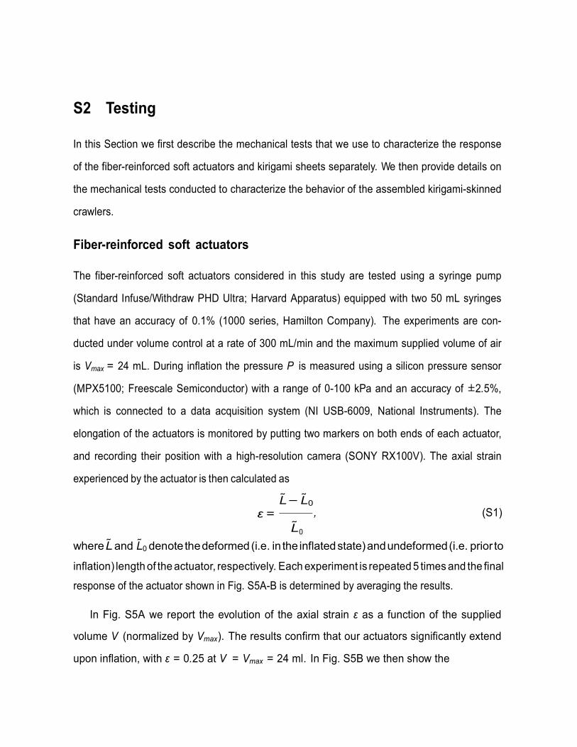
experienced by the actuator is then calculated as
L L0
ε = L
, (S1)
where L and L0 denote the deformed (i.e. in the inflated state) and undeformed (i.e. prior to
inflation) length of the actuator, respectively. Each experiment is repeated 5 times and the final
response of the actuator shown in Fig. S5A-B is determined by averaging the results.
In Fig. S5A we report the evolution of the axial strain ε as a function of the supplied
volume V (normalized by Vmax). The results confirm that our actuators significantly extend
upon inflation, with ε = 0.25 at V = Vmax = 24 ml. In Fig. S5B we then show the
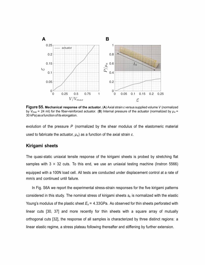
Figure S5. Mechanical response of the actuator. (A) Axial strain ε versus supplied volume V (normalized by Vmax = 24 ml) for the fiber-reinforced actuator. (B) Internal pressure of the actuator (normalized by µa = 30 kPa) as a function of its elongation.
evolution of the pressure P (normalized by the shear modulus of the elastomeric material
used to fabricate the actuator, µa) as a function of the axial strain ε.
Kirigami sheets The quasi-static uniaxial tensile response of the kirigami sheets is probed by stretching flat
samples with 3 × 32 cuts. To this end, we use an uniaxial testing machine (Instron 5566)
equipped with a 100N load cell. All tests are conducted under displacement control at a rate of
mm/s and continued until failure.
In Fig. S6A we report the experimental stress-strain responses for the five kirigami patterns
considered in this study. The nominal stress of kirigami sheets sk is normalized with the elastic
Young’s modulus of the plastic sheet Es = 4.33GPa. As observed for thin sheets perforated with
linear cuts [30, 37] and more recently for thin sheets with a square array of mutually
orthogonal cuts [32], the response of all samples is characterized by three distinct regions: a
linear elastic regime, a stress plateau following thereafter and stiffening by further extension.
0 0.25 0.5 0.75 10
0.05
0.1
0.15
0.2
0.25
0 0.05 0.1 0.15 0.2 0.250
0.2
0.4
0.6
0.8
1actuator
A B
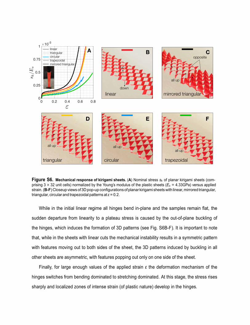
Figure S6. Mechanical response of kirigami sheets. (A) Nominal stress sk of planar kirigami sheets (com- prising 3 × 32 unit cells) normalized by the Young’s modulus of the plastic sheets (Es = 4.33GPa) versus applied strain. (B-F) Closeup views of 3D pop-up configurations of planar kirigami sheets with linear, mirrored triangular, triangular, circular and trapezoidal patterns at ε = 0.2.
While in the initial linear regime all hinges bend in-plane and the samples remain flat, the
sudden departure from linearity to a plateau stress is caused by the out-of-plane buckling of
the hinges, which induces the formation of 3D patterns (see Fig. S6B-F). It is important to note
that, while in the sheets with linear cuts the mechanical instability results in a symmetric pattern
with features moving out to both sides of the sheet, the 3D patterns induced by buckling in all
other sheets are asymmetric, with features popping out only on one side of the sheet.
Finally, for large enough values of the applied strain ε the deformation mechanism of the
hinges switches from bending dominated to stretching dominated. At this stage, the stress rises
sharply and localized zones of intense strain (of plastic nature) develop in the hinges.
0 0.2 0.4 0.6 0.80
0.25
0.5
0.75
1 10-3
lineartriangularcirculartrapezoidalmirrored triangular
linear mirrored triangular
triangular circular trapezoidal
A B C
D E F
up
down
opposite
all up
all up all upall up

Figure S7. Mechanical response of kirigami-skinned crawlers. (A) Axial strain ε versus supplied volume V for the kirigami-skinned crawlers. Inset shows definition of L0 and L0. (B) Internal pressure P versus axial strain ε for the kirigami-skinned crawler. (C) Internal pressure P versus axial strain ε for the crawlers with a kirigami skin comprising an array with dimension reported in Section S1 (solid line) and a looser skin with all dimensions increased by 10% (dashed linev).
Kirigami-skinned crawlers
Three different set of tests are conducted to characterize the mechanical response of the
assembled kirigami-skinned crawlers: one set to characterize their elongation and pressure as
a function of the supplied volume, another set to investigate how inflation affects the
frictional force when they move on a substrate and a final set to characterize their locomotion.
Elongation and pressure The evolution of the elongation and pressure of our kirigami-skinned crawlers upon inflation is
characterized with an experimental procedure identical to that used for the fiber-reinforced soft
actuators. However, it is important to note that for the kirigami-skinned crawlers the axial strain
ε is calculated using the length of the perforated part of the skin,
L L0 ε = ,
(S2) L0
where L0 and L denote the undeformed and deformed lengths of the perforated part of the
skin (see inset in Fig. S7A). In Fig. S7A and S7B we report the experimental results obtained
0 0.25 0.5 0.75 10
0.05
0.1
0.15
0.2
0.25
0 0.05 0.1 0.15 0.2 0.250
0.2
0.4
0.6
0.8
1CA B
0 0.05 0.1 0.15 0.2 0.250
0.2
0.4
0.6
0.8
1
actuatorlineartriangularcirculartrapezoidalmirrored triangular
triangularloose triangular

for the actuators covered with the five different kirigami skins considered in this study and for
comparison, we also include the results of the fiber-reinforced actuator (dashed gray line). First,
we find that kirigami skins comprising an array of triangular, circular, trapezoidal and mirrored
triangular cuts only moderately limit the extensibility of the soft actuator. By contrast, when a
kirigami sheet with linear cuts is wrapped around the actuator, the extensibility of the resulting
crawler is almost completely suppressed. This is because the symmetric out-of-plane buckling
mode of the sheet with linear cuts is prevented by the presence of the actuator (see Fig. S8). As
such, no mechanical instability is triggered in the kirigami sheet with linear cuts upon inflation,
resulting in linear and very stiff response (see red line in Fig. S7A)
Second, Fig. S7B reveals that, with the exception of the kirigami-skinned crawler with linear
cuts, all other crawlers are characterized by a pressure-elongation evolution qualitatively
identical to the stress-strain curves shown in Fig. S6A (i.e. characterized by a initial linear
regime, a pressure plateau and final stiffening). However, in the kirigami-skinned crawlers the
transition between the plateau and the stiffening regimes occurs at much lower values of axial
strain compared to the corresponding kirigami sheets. To understand the reason behind this
difference, we fabricate and test an additional kirigami-skinned crawler covered by a looser
skin with triangu- lar cuts. More specifically, in this looser skin all dimensions are increased by
10% compared to those described in Section S1. The results reported in Fig. S7C show that the
transition between the plateau and the stiffening regimes is postponed in the actuator with the
looser skin (i.e. it occurs at ε ∼ 0.15 instead of at ε ∼ 0.08). This indicates that the start of
the stiffening regime in the kirigami soft-crawler is not due to the stretching of the hinges (as
for the kirigami sheets), but to the interaction between the skin and the actuator. Upon inflation,
because of both the bulging of the actuator and the positive Poisson’s ratio of the kirigami
sheets (which results in shrinkage of their cross-section), the kirigami sheet and the actuator
get in contact. At that point the actuator starts pushing the skin, limiting its out-of-plane
deformation and increasing its axial stiffness.

Finally, in Fig. S8 we report snapshots showing the evolution of the surface morphology as
a function of the supplied volume for the kirigami-skinned crawlers considered in this study.
Figure S8. Evolution of surface morphology for our kirigami-skinned crawlers. Closeup views of our kirigami-skinned crawlers at different inflation levels.
Friction force
We conduct a set of tests to measure how inflation affects the frictional force when the crawlers
move on a substrate. Specifically, in these experiments the crawlers are placed on a rough
surface (polyurethane foam) and pushed (i.e. moved in forward direction) and pulled (i.e.
moved in backward direction) for 10 mm at a constant rate of 1 mm/s using a motorized
translation stage (MTS50-Z8 - Thorlabs). The resistive force in the direction of the motion (i.e.
the friction force), Ff r , is measured using a 1 lb Load Cell (LSB200 Miniature S-Beam Load
Cell, FUTEK Advanced Sensor Technology, Inc.) (see Fig. S9). We consider both the fiber-
reinforced soft actuator (without kirigami skin) and kirigami-skinned crawlers with linear,
triangular, circular, trapezoidal and mirrored triangular patterns. In all our tests the crawlers
are pushed and pulled 5 times for different values of supplied volume (i.e. V = 0, 6, 12,
18, 24 mL), the last 3 of which are analyzed to characterize frictional properties of crawlers
linear mirrored triangular triangular circular trapezoidal
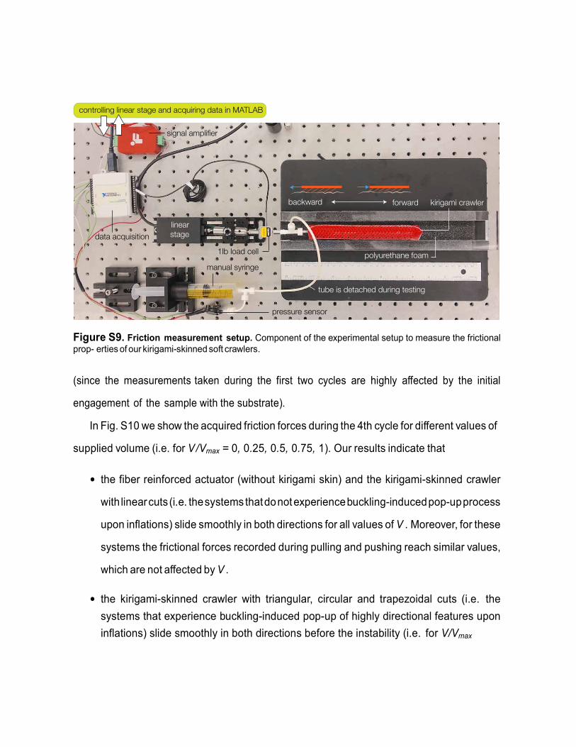
Figure S9. Friction measurement setup. Component of the experimental setup to measure the frictional prop- erties of our kirigami-skinned soft crawlers.
(since the measurements taken during the first two cycles are highly affected by the initial
engagement of the sample with the substrate).
In Fig. S10 we show the acquired friction forces during the 4th cycle for different values of
supplied volume (i.e. for V /Vmax = 0, 0.25, 0.5, 0.75, 1). Our results indicate that
• the fiber reinforced actuator (without kirigami skin) and the kirigami-skinned crawler
with linear cuts (i.e. the systems that do not experience buckling-induced pop-up process
upon inflations) slide smoothly in both directions for all values of V . Moreover, for these
systems the frictional forces recorded during pulling and pushing reach similar values,
which are not affected by V .
• the kirigami-skinned crawler with triangular, circular and trapezoidal cuts (i.e. the
systems that experience buckling-induced pop-up of highly directional features upon
inflations) slide smoothly in both directions before the instability (i.e. for V/Vmax
forwardbackward kirigami crawler
linearstage
1lb load cell polyurethane foam
pressure sensor
manual syringe
tube is detached during testing
data acquisition
controlling linear stage and acquiring data in MATLAB
signal amplifier

≤ 0.25). Differently, for V /Vmax > 0.25 the buckling-induced popping-out of the
features defined by the cuts leads to a jerking motion in backward direction, with the
crawlers that alter- natively stick to the substrate and slide over it. Such stick-slip
regime is also apparent from the measured frictional force which presents a discrete
sequence of sharp drops. On the other hand, the friction force is almost constant and the
crawler slides smoothly when pushed in the forward direction (i.e. for 10s < t < 20s).
Finally, we also note that the instability-induced pop-up process results in a
significant increase of the magnitude of Ff r measured during pulling.
• the kirigami-skinned crawler with mirrored triangular cuts (i.e. the system that experience
buckling-induced pop-up of symmetric features upon inflations) slides smoothly in both
directions before the instability. Since the mirrored pattern is inherently stiffer than the
triangular one larger volumes should be supplied to trigger the instability and initiate the
pop-up (i.e. V /Vmax ∼ 0.5). For V /Vmax > 0.5 the buckling-induced popping-out of
the features defined by the cuts leads to a jerking motion in both backward and forward
direction and a significant increase of the magnitude of Ff r measured during both pulling
and pushing.
An effective coefficient of friction in backward (µb) and forward (µf ) directions is then
extracted from our force measurements as
, ,peak peak
b f
b fN N
F Fu
F F (S3)
where NF 0.2 N is the crawler’s weight, · denotes the mean value and peak
bF and peak
fF are
the local peaks of Ffr recorded during pulling and pushing, respectively. Note that these peaks
are calculated using the MATLAB findpeaks function with
MinPeakProminence = max(Ff r ) and MinPeakHeight = 0.5 max(Ff r ).
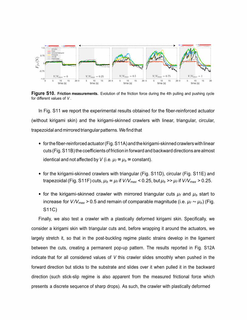
Figure S10. Friction measurements. Evolution of the friction force during the 4th pulling and pushing cycle for different values of V .
In Fig. S11 we report the experimental results obtained for the fiber-reinforced actuator
(without kirigami skin) and the kirigami-skinned crawlers with linear, triangular, circular,
trapezoidal and mirrored triangular patterns. We find that
• for the fiber-reinforced actuator (Fig. S11A) and the kirigami-skinned crawlers with linear
cuts (Fig. S11B) the coefficients of friction in forward and backward directions are almost
identical and not affected by V (i.e. µf ≃ µb ≃ constant).
• for the kirigami-skinned crawlers with triangular (Fig. S11D), circular (Fig. S11E) and
trapezoidal (Fig. S11F) cuts, µb ≃ µf if V /Vmax < 0.25, but µb >> µf if V /Vmax > 0.25.
• for the kirigami-skinned crawler with mirrored triangular cuts µf and µb start to
increase for V /Vmax > 0.5 and remain of comparable magnitude (i.e. µf ∼ µb) (Fig.
S11C)
Finally, we also test a crawler with a plastically deformed kirigami skin. Specifically, we
consider a kirigami skin with triangular cuts and, before wrapping it around the actuators, we
largely stretch it, so that in the post-buckling regime plastic strains develop in the ligament
between the cuts, creating a permanent pop-up pattern. The results reported in Fig. S12A
indicate that for all considered values of V this crawler slides smoothly when pushed in the
forward direction but sticks to the substrate and slides over it when pulled it in the backward
direction (such stick-slip regime is also apparent from the measured frictional force which
presents a discrete sequence of sharp drops). As such, the crawler with plastically deformed
0 5 10 15 200 5 10 15 200 5 10 15 200 5 10 15 200 5 10 15 20-1.5
-0.75
0
0.75
1.5
time (s) time (s) time (s) time (s) time (s)
actuatorlinearmirrored triangulartriangularcirculartrapezoidal

Figure S11. Effective friction coefficients. Effective friction coefficients for (A) the fiber-reinforced soft ac- tuator and kirigami-skinned crawlers with (B) linear, (C) mirrored triangular, (D) triangular, (E) circular and (F) trapezoidal cuts.
kirigami skin exhibits highly anisotropic frictional properties through the entire actuation process
(Fig. S12B).
Locomotion To characterize the ability of our kirigami-skinned crawler to move we place them on a rough
surface (polyurethane foam) and repeatedly inflate them by supplying 24 mL of air and
deflate them by extracting the same amount of fluid. During these tests we record the motion
of the crawlers using a high-resolution camera (SONY RX100V) at a frame rate of 30 fps
and determine their displacement using an open-source digital image correlation and tracking
0 0.25 0.5 0.75 10
2
4
6
8
0 0.25 0.5 0.75 10
2
4
6
8
0 0.25 0.5 0.75 1 0 0.25 0.5 0.75 1
0 0.25 0.5 0.75 1 0 0.25 0.5 0.75 1
actuator linear mirrored triangular
triangular circular trapezoidal
A B C
D E F

Figure S12. Frictional properties of a crawler with a plastically deformed skin. (A) Evolution of the friction force during the 4th pulling and pushing cycle for different values of V . (B) Effective friction coefficients in forward and backward direction for the plastically deformed kirigami-skinned crawlers.
package [38]. Specifically, we track the position of 16 markers uniformly placed on the skin
of the crawlers and use these data to characterize displacement, velocity and location of the
anchor point.
While in Fig. 3 of the main text we present results for the tethered crawlers that are actuated
pneumatically using air transferred to them from a stationary source via a flexible tube, we also
characterize the ability to move of an untethered kirigami-skinned crawler with trapezoidal cuts.
In this case the tests are conducted under pressure control conditions, the maximum pressure
is set to Pmax = 16 kPa and the minimum pressure is varied (i.e Pmin = 1 kPa, 4 kPa, 8 kPa
and 12 kPa) and we use the on-board pressure sensor to switch between inflation and deflation.
In Fig. S13A we report the pressure signal detected by the on-board pressure sensor in our
experiments, while in Fig. S13B we show the corresponding displacement of the center of the
crawler. Similarly to the case of the corresponding tethered crawler, also here we find that
the locomotion efficiency of the crawlers can be improved by carefully choosing the minimum
pressure. Specifically, we find that the tested crawler with Pmin = 1 kPa, 4 kPa, 8 kPa and
0 8 16 24 32-1.5
-0.75
0
0.75
1.5
time (s)
00.250.50.751
A
0 0.25 0.5 0.75 1
B
0
2
4
6
8
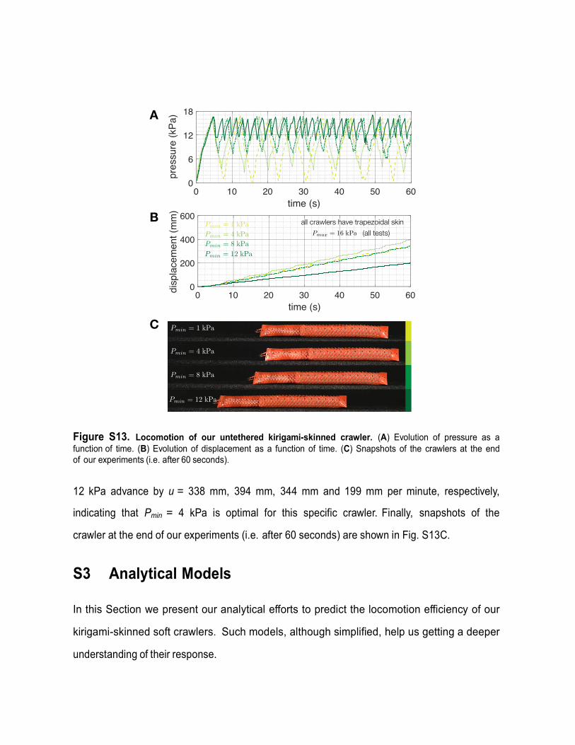
Figure S13. Locomotion of our untethered kirigami-skinned crawler. (A) Evolution of pressure as a function of time. (B) Evolution of displacement as a function of time. (C) Snapshots of the crawlers at the end of our experiments (i.e. after 60 seconds).
12 kPa advance by u = 338 mm, 394 mm, 344 mm and 199 mm per minute, respectively,
indicating that Pmin = 4 kPa is optimal for this specific crawler. Finally, snapshots of the
crawler at the end of our experiments (i.e. after 60 seconds) are shown in Fig. S13C.
S3 Analytical Models In this Section we present our analytical efforts to predict the locomotion efficiency of our
kirigami-skinned soft crawlers. Such models, although simplified, help us getting a deeper
understanding of their response.
0 10 20 30 40 50 60time (s)
0
200
400
600
disp
lace
men
t (m
m)
0 10 20 30 40 50 60time (s)
0
6
12
18
pres
sure
(kPa
)A
B
C
all crawlers have trapezoidal skin (all tests)

Relation between the location of the anchor point and the measured effective friction coefficients
To connect the measured effective coefficients of friction (µf and µb) of our kirigami-skinned
crawlers to the location of their anchor point (xa), we neglect inertial forces (due to slow nature
of the crawling motion) and impose static equilibrium in the direction of motion by balancing
the friction forces acting on the two sides of the crawlers’ instantaneous anchor point (see
Fig. S14). Assuming that the mass of crawlers is uniformly distributed along their length with
a linear density ρ = m/L, we find that during inflation
1
21
2
0,a
a
x L
b fL xg dx g dx
(S4)
while during deflation
1
21
2
0,a
a
x L
f bL xg dx g dx
(S5)
where xa denote the position of the anchor point measured from the center of mass. By solving
Eqs. (S4) and (S5) we find that
inflation deflation
1 1, ,
2 2b f b fa a
b f b f
x x
L L
(S6)
which provide explicit relations between the position of the anchor point and the frictional
properties of the kirigami skin. Eqs. (S6) clearly indicate that, to maximize the distance traveled
by the crawlers, the ratio µb/µf should be as large as possible. In such case, xa/L → ±0.5 and
anchoring occurs at the tail during inflation/elongation and at the head during
deflation/shortening, completely preventing backward sliding. Moreover, Eqs. (S6) also show
that for µb ∼ µf the anchor point is located at the center of mass of the crawlers (i.e. xa/L
∼ 0). In such case the head and tail of the crawlers move by the same amount (but in
opposite directions) during inflation and deflation and there is no advancement.

a
a
Figure S14. Relation between the location of the anchor point and the fraction coefficients. (A) Snapshot of our crawler. (B) Friction forces acting on the crawler during inflation. (C) Friction forces acting on the crawler during deflation.
As for the error of the model with respect to the experimental data, it is important to mention
that in our simple analysis we assume quasi-static equilibrium and homogeneous deformations
our experiments show that the deformation is not always homogeneous. Furthermore, an ad-
ditional source of error is introduced during processing of the experimental data (i.e. when
extracting the anchor point from the recorded experimental movies). To quantify the difference
between the position of the anchor point as predicted by our model (xm) and measured from
our experiments (xe ), we calculate the normalized root-mean-square error
NRMSD =
2
1
max minmax min
100n m e
a ai ix x
x xnx x
(S7)
where xmax = L/2 and xmin = L/2 are respectively the maximum and minimum values for
the position of the anchor point and n = 8 is the number of available data points. We find
that NRMSD = 13.5%, 12.1%, 15.9% and 9.4% for the kirigami skins with triangular, circular,
trapezoidal and mirrored triangular cuts, respectively.
anchor point
inflation
deflation
anchor point
0
A
B
C

Estimation of the total distance traveled by the crawlers The total distance traveled by the crawlers, utot, when a total volume Vtot of air is supplied by
cyclically inflating and deflating them between Vmax and Vmin can be calculated as
max min
min max0
V Vtot a a
V V
u x xd dN dV dV
L L dV L dV
(S8)
where N = (Vmax Vmin)/Vtot are xa denotes the position of the anchor point.
S4 Finite Element Simulations
In this Section, we present the results of Finite Element (FE) simulations conducted to study
the effect of the cut shape on the stretchability of the corresponding kirigami skin. All simula-
tions are conducted using the commercial package Abaqus\Standard 6.14 (Dassault Systemes).
Moreover, in all analyses we consider flat sheets, discretize them with 3D shell elements (S4R)
and model the cuts as seam cracks with duplicate overlapping nodes along the cuts. Finally, to
reduce the computational cost and make sure the response of the system is not dominated by
boundary effects, we investigate the response of infinite perforated flat sheets using a unit cell
and periodic boundary conditions. Since here we are mostly interested in the response of the
perforated sheet immediately after buckling (i.e. before the plastic deformation takes place),
for this set of simulations we use a linear elastic material model (with E = 4.33 GPa and
ν = 0.4). All simulations consist of two steps: (i) we first use a linear perturbation analysis
(*BUCKLE module in Abaqus) to identify the critical buckling mode; (ii) we then introduce a
small imperfection ( ; 0.001l) in the form of the critical mode into the mesh to guide the post-
buckling analysis. For this step we conduct dynamic implicit simulations (*DYNAMIC module
in Abaqus) and to facilitate convergence, we introduce some artificial numerical damping.
In Fig. S15A-C we present the stress-strain curves obtained for unit cells with triangular,
circular and trapezoidal cuts when stretched uniaxially (note that ε is the applied strain and sk

Figure S15. Finite-element simulations of kirigami unit cells. Stress-strain curves for unit cells with triangu- lar, circular and trapezoidal cuts for (A) δ/l = 0.111 (B) δ/l = 0.156 (C) δ/l = 0.2 (D) Snapshot of undeformed (ε = 0) and deformed configurations of unit cells for ε = 0.2 and ε = 0.4. Note that in our simulations we consider an elastic sheet with thickness t = 51µm, Young’s modulus E = 4.33 GPa and Poisson’s ratio ν = 0.4.
0 0.1 0.2 0.3 0.40
0.5
1
1.5
2
0 0.1 0.2 0.3 0.40
0.5
1
1.5
2
0 0.1 0.2 0.3 0.40
0.5
1
1.5
2triangularcirculartrapezoidal
A B C
D

is the measured nominal stress). Three different hinge widths are considered, i.e. δ/l = 0.111
(see Fig. S15A), 0.156 (see Fig. S15B) and 0.2 (see Fig. S15C). The simulations confirm the
trends observed in experiments (see Fig. S6A) and indicate that the pattern with trapezoidal cut
is the most stretchable. Moreover, as expected, they indicate that by increasing the hinge width,
δ/l, the kirigami sheets become stiffer.
S5 Description of Supporting Movies Movie S1. Rectilinear gait of a female Dumeril’s boa. The snake actively tilts the ventral scales
to increase frictional anisotropy and enhance anchoring (courtesy of H. Marvi and D. Hu).
Movie S2. A fiber-reinforced extending actuator is placed over a rough surface and is subjected
to cyclic inflation/deflation. Since symmetry results in equal movement of both actuator ends
during inflation and deflation, it does not move forward.
Movie S3. Assembly of a kirigami-skinned soft crawler.
Movie S4. Motion of the crawlers during six inflation cycles with V ∈ [0,24] ml.
Movie S5. Motion of the crawlers when a total volume Vtot = 120 ml of air is supplied by
cyclically inflating and deflating them between Vmax = 24 ml and Vmin ∈ [0,Vmax].
Movie S6. Fully untethered kirigami skinned crawlers with triangular, circular, and trapezoidal
kirigami skins. Note that the rear part of the crawler is rigid and contains the control unit.
Therefore, the pop-up of the portion of the skin that covers it is not that pronounced.
Movie S7. An untethered crawler with circular kirigami skin propels itself over asphalt.
Movie S8. An untethered crawler with trapezoidal kirigami skin climbs a concrete ramp.
Movie S9. An untethered crawler with triangular kirigami skin propels itself over rough stone.
Note that the two vertical bands appearing on the kirigami skin during inflation are due to
lighting, since in those locations the control unit beneath the skin is covered with black tape.
Movie S10. Motion of an untethered crawler with trapezoidal kirigami skin for Pmin = 1, 4, 8,
and 12 kPa and Pmax = 16 kPa. The top left panel shows the real-time pressure inside the
actuator, while the top right panel reports the position of the center of mass of the crawler over
time.
![Soft Robotics: Self-walking, self-learning bipedal robot · Actuator” [MPA] is a soft pneumatic actuator utilizing the elastic properties of rubber. The MPA has been initially developed](https://img.dokumen.tips/doc/110x75/5f8263a0e309ac562212bef3/soft-robotics-self-walking-self-learning-bipedal-actuatora-mpa-is-a-soft-pneumatic.jpg)