Embed Size (px)
Citation preview

24/02/2016
1
Kirchhoff’s Voltage and Current Laws
• Node
– a point in a circuit where two or more circuit components are joined
• Loop– any closed path that passes through no node more than once
• Mesh– a loop that contains no other loop
• Examples:
– A, B, C, D, E and F are nodes
– the paths ABEFA, BCDEB and ABCDEFA are loops
– ABEFA and BCDEB are meshes
Kirchhoff’s Laws
24/02/2016
2
• Kirchhoff’s Voltage Law (KVL)
At any instant the algebraic sum of all the voltages around any loop in a circuit is zero
KVL around loop ABEFA:
Proof:
or with the voltage polarities reversed:
Example 1: Let us write KVL around loop ABCDEFA

24/02/2016
3
Example 2: Let us write KVL around loop ABEFA
Example 3: Let us write KVL around loop BCDEB

24/02/2016
4
Example 4: Notice in the series example given earlier that the sum of the resistor voltages is equal to the source voltage.
I1= R1= 0.68 k V1= P1=
I2= R2= 1.50 k V2= P2=
I3= R3= 2.20 k V3= P3=
IT= RT= 4.38 k VS= 12 V PT= 2.74 mA
2.74 mA
2.74 mA
2.74 mA 1.86 V
4.11 V
6.03 V
5.1 mW
11.3 mW
16.5 mW
32.9 mW
KVL: Vs V1 V2 V3 = 0
• Kirchhoff’s Current Law (KCL)
At any instant, the algebraic sum of all the currents flowing into any node in a circuit is zero
– Label the currents flowing into the node as positiveand the currents flowing out of the node as negative
24/02/2016
5
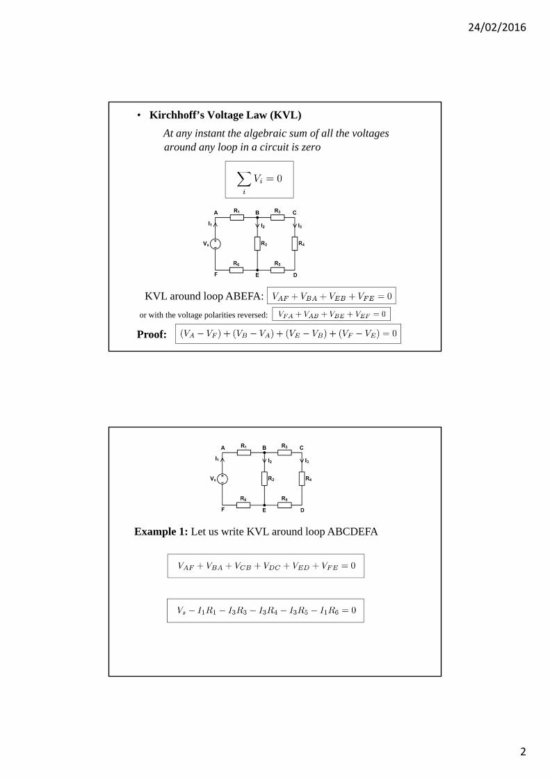
Example 1: Let us write KCL at node A
Example 2: Let us write KCL at node B
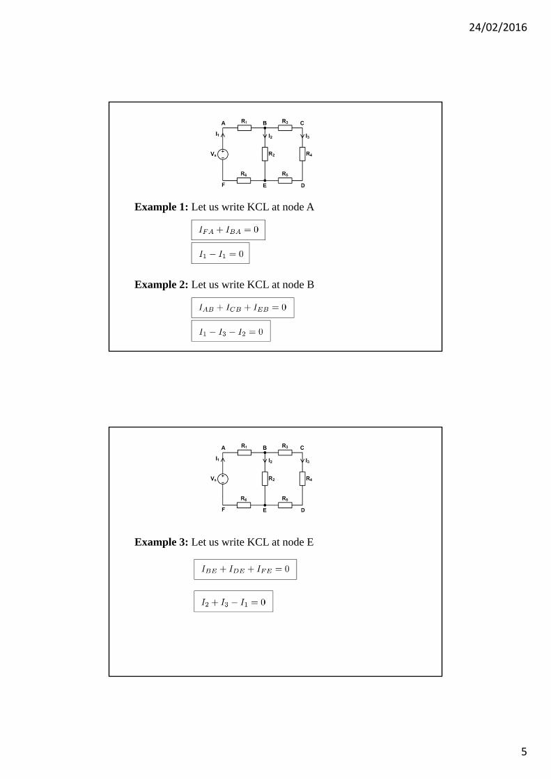
Example 3: Let us write KCL at node E

24/02/2016
6
Example 4: Notice in the parallel resistors example given earlier, the current from the source was equal to the sum of the branch currents.
I1= R1= 0.68 k V1= P1=
I2= R2= 1.50 k V2= P2=
I3= R3= 2.20 k V3= P3=
IT= RT= 386 VS= 5.0 V PT=
5.0 V
5.0 V
5.0 V
13.0 mA
2.3 mA
3.3 mA
7.4 mA 36.8 mW
16.7 mW
11.4 mW
64.8 mW
KCL: Is I1 I2 I3 = 0
Total power in an electrical circuit should be zero, i.e., generated power should be equal to the dissipated power. A negative value for the power indicates that it is a generated power.
Total Power
Example 1:

24/02/2016
7
Example 2: Notice in the series example given earlier that the sum of the resistor voltages is equal to the source voltage.
I1= R1= 0.68 k V1= P1=
I2= R2= 1.50 k V2= P2=
I3= R3= 2.20 k V3= P3=
IT= RT= 4.38 k VS= 12 V PT= 2.74 mA
2.74 mA
2.74 mA
2.74 mA 1.86 V
4.11 V
6.03 V
5.1 mW
11.3 mW
16.5 mW
32.9 mW
KVL: Vs V1 V2 V3 = 0
Example 3: Notice in the parallel resistors example given earlier, the current from the source was equal to the sum of the branch currents.
I1= R1= 0.68 k V1= P1=
I2= R2= 1.50 k V2= P2=
I3= R3= 2.20 k V3= P3=
IT= RT= 386 VS= 5.0 V PT=
5.0 V
5.0 V
5.0 V
13.0 mA
2.3 mA
3.3 mA
7.4 mA 36.8 mW
16.7 mW
11.4 mW
64.8 mW
KCL: Is I1 I2 I3 = 0

24/02/2016
8
Example: Consider the electrical circuit below
a) Find Io.
b) Verify that the total power dissipated equals to the
total power generated.
Solution:

24/02/2016
9
Example : (with dependent sources)
Consider the electrical circuit below
a) Find I1, I2, I3 and I4.
b) Verify the power condition (Pdissipated = Pgenerated)

24/02/2016
10
Solution:
24/02/2016
11
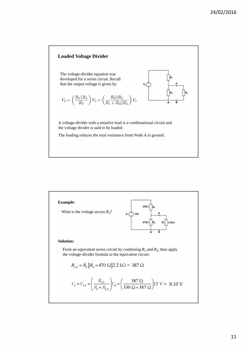
Loaded Voltage Divider
A voltage-divider with a resistive load is a combinational circuit and the voltage divider is said to be loaded.
The loading reduces the total resistance from Node A to ground.
The voltage-divider equation was developed for a series circuit. Recall that the output voltage is given by
What is the voltage across R3?
Form an equivalent series circuit by combining R2 and R3; then apply the voltage-divider formula to the equivalent circuit:
8.10 V
Solution:
Example:

24/02/2016
12
Stiff voltage divider
A stiff voltage-divider is one in which the loaded voltage nearly the same as the no-load voltage. To accomplish this, the load current must be small compared to the bleeder current (or RL is large compared to the divider resistors).
If R1 = R2 = 1.0 k, what value of RL will make the divider a stiff voltage divider? What fraction of the unloaded voltage is the loaded voltage?
RL > 10 R2; RL should be 10 k or greater.
This is 95% of the unloaded voltage.
Example:
Solution:
For a 10 k load,
Loading Effect of a Voltmeter
All measurements affect the quantity being measured. A voltmeter has internal resistance, which can change the resistance of the circuit under test. In this case, a 1 M internal resistance of the meter accounts for the readings.
Assume VS = 10 V, but the meter reads only 4.04 V when it is across either R1 or R2.
10 V
Can you explain what is happening?
4.04 V
4.04 V
24/02/2016
13
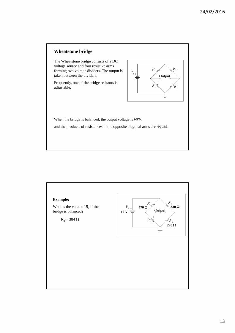
Wheatstone bridge
The Wheatstone bridge consists of a DC voltage source and four resistive arms forming two voltage dividers. The output is taken between the dividers.
Frequently, one of the bridge resistors is adjustable.
When the bridge is balanced, the output voltage is zero,
and the products of resistances in the opposite diagonal arms are equal.
Example:
What is the value of R2 if the bridge is balanced?
470 330
270
12 V
R2 = 384
24/02/2016
14
Troubleshooting
The effective troubleshooter must think logically about circuit operation.
Understand normal circuit operation and find out the symptoms of the failure.
Decide on a logical set of steps to find the fault.
Following the steps in the plan, make measurements to isolate the problem.
Modify the plan if necessary.
Analysis:
Planning:
Measurement:
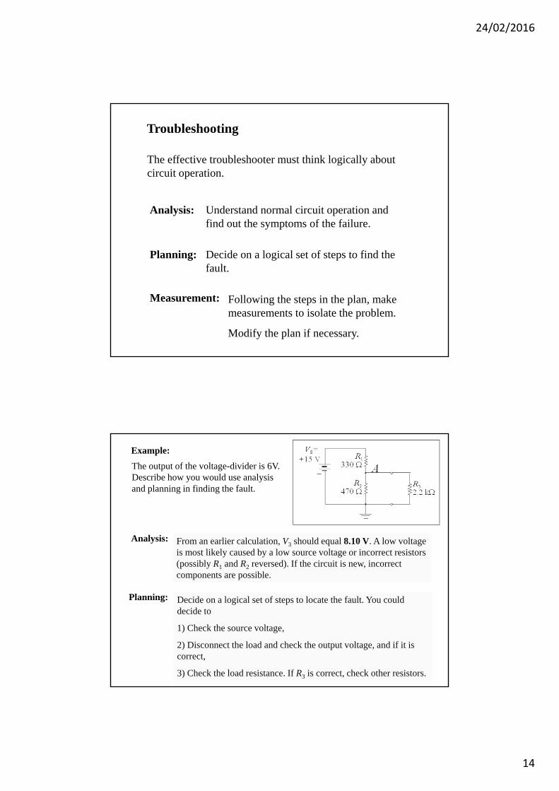
The output of the voltage-divider is 6V. Describe how you would use analysis and planning in finding the fault.
From an earlier calculation, V3 should equal 8.10 V. A low voltage is most likely caused by a low source voltage or incorrect resistors (possibly R1 and R2 reversed). If the circuit is new, incorrect components are possible.
Decide on a logical set of steps to locate the fault. You could decide to
1) Check the source voltage,
2) Disconnect the load and check the output voltage, and if it is correct,
3) Check the load resistance. If R3 is correct, check other resistors.
A
Example:
Analysis:
Planning: