Embed Size (px)
Citation preview
IntroductionStep by step
ElectronicsKirchhoff’s Law Example
Terry Sturtevant
Wilfrid Laurier University
March 14, 2012
Terry Sturtevant Electronics Kirchhoff’s Law Example
IntroductionStep by step Overview
Analyzing the behaviour of DC circuits involving only DC (ie.unchanging in time) voltage sources and ohmic devices can bedone using Kirchhoff’s Laws.
Terry Sturtevant Electronics Kirchhoff’s Law Example
IntroductionStep by step Overview
All of these calculations assume that the current through adevice is proportional to the voltage across the device.
A device for which this is true is considered “ohmic”.For many devices the relationship may be far more complex,and so the equations relating voltages and currents in thecircuit become non-linear and are much harder to solve.
Terry Sturtevant Electronics Kirchhoff’s Law Example

IntroductionStep by step Overview
All of these calculations assume that the current through adevice is proportional to the voltage across the device.A device for which this is true is considered “ohmic”.
For many devices the relationship may be far more complex,and so the equations relating voltages and currents in thecircuit become non-linear and are much harder to solve.
Terry Sturtevant Electronics Kirchhoff’s Law Example

IntroductionStep by step Overview
All of these calculations assume that the current through adevice is proportional to the voltage across the device.A device for which this is true is considered “ohmic”.For many devices the relationship may be far more complex,and so the equations relating voltages and currents in thecircuit become non-linear and are much harder to solve.
Terry Sturtevant Electronics Kirchhoff’s Law Example

IntroductionStep by step Overview
These laws areAt any point in a circuit, the sum of the currents flowing towardthe point is equal to the sum of the currents flowing away from thepoint; or, the algebraic sum of all the currents flowing toward anode is equal to zero. ∑
I = 0
Terry Sturtevant Electronics Kirchhoff’s Law Example

IntroductionStep by step Overview
In any closed circuit, the algebraic sum of all the voltages aroundthe loop is equal to zero; or, the sum of all voltage sources is equalto the sum of all IR drops1. (In this case “voltage sources” can bepositive or negative.) ∑
V =∑
IR
1The path around a loop is a series of voltage “steps”, in which, at the endof the loop, you must return to the same voltage you started with. There areonly two kinds of voltages in the circuit. Those due to sources, such asbatteries, and those due to sinks, which are resistors. By Ohm’s law, thevoltage across a resistor is IR.
Terry Sturtevant Electronics Kirchhoff’s Law Example

IntroductionStep by step Overview
The way that these laws are applied to analyze a circuit involveschoosing nodes in the circuit for the first law and using loops inthe circuit for the second and producing equations from each nodeand loop.
Terry Sturtevant Electronics Kirchhoff’s Law Example

IntroductionStep by step Overview
After the equations are created, determining the currents in thecircuit is accomplished by solving the equations simultaneously. Inthis case, the system we must solve is of the form
AX = B
where A is the coefficient matrix and X is the vector of thecurrents. (Because of the two types of equations used, B is avector of voltages and zeros.)
Terry Sturtevant Electronics Kirchhoff’s Law Example

IntroductionStep by step Overview
If a solution exists, it may be found by
X = A−1B
where A−1 is the inverse of the coefficient matrix. (A solution willnot exist if you have, for instance, erroneously connected twodifferent voltage sources in parallel.)
Terry Sturtevant Electronics Kirchhoff’s Law Example

IntroductionStep by step Overview
So far no mention has been made of the dimension of thecoefficient matrix. Clearly, to be invertible A must be square,however you will probably have many more equations than currents.This is because the equations are not all linearly independent. Inother words, some of the equations are redundant, and will have tobe eliminated for the system to be solvable.
Terry Sturtevant Electronics Kirchhoff’s Law Example

IntroductionStep by step Overview
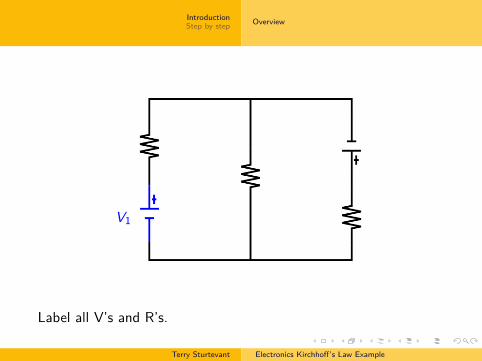
Label all V’s and R’s.
Terry Sturtevant Electronics Kirchhoff’s Law Example
IntroductionStep by step Overview
V1
Label all V’s and R’s.
Terry Sturtevant Electronics Kirchhoff’s Law Example

IntroductionStep by step Overview
V2
Label all V’s and R’s.
Terry Sturtevant Electronics Kirchhoff’s Law Example
IntroductionStep by step Overview
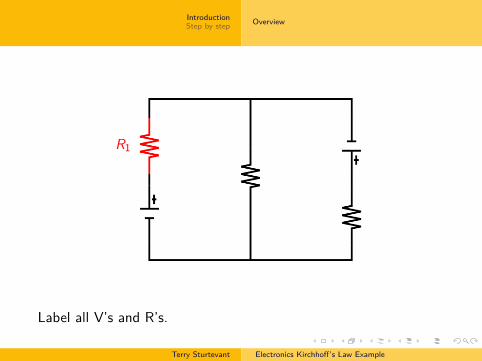
R1
Label all V’s and R’s.
Terry Sturtevant Electronics Kirchhoff’s Law Example
IntroductionStep by step Overview
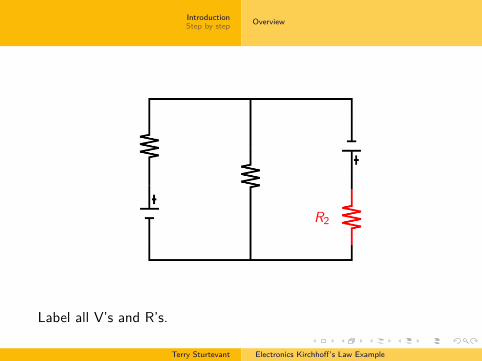
R2
Label all V’s and R’s.
Terry Sturtevant Electronics Kirchhoff’s Law Example

IntroductionStep by step Overview
R3
Label all V’s and R’s.
Terry Sturtevant Electronics Kirchhoff’s Law Example

IntroductionStep by step Overview
R1 I1
6
Label all I’s to go with R’s and pick directions for I’s.
Terry Sturtevant Electronics Kirchhoff’s Law Example

IntroductionStep by step Overview
R2 I2?
Label all I’s to go with R’s and pick directions for I’s.
Terry Sturtevant Electronics Kirchhoff’s Law Example
IntroductionStep by step Overview
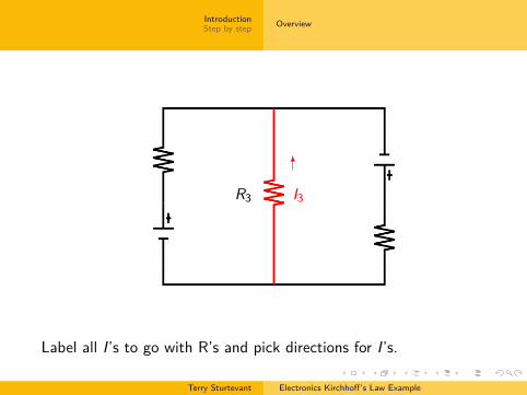
R3 I3
6
Label all I’s to go with R’s and pick directions for I’s.
Terry Sturtevant Electronics Kirchhoff’s Law Example

IntroductionStep by step Overview
L1
���?
Label loops.
Terry Sturtevant Electronics Kirchhoff’s Law Example

IntroductionStep by step Overview
L2
���?
Label loops.
Terry Sturtevant Electronics Kirchhoff’s Law Example

IntroductionStep by step Overview
L3'
&
$
%�
Label loops.
Terry Sturtevant Electronics Kirchhoff’s Law Example

IntroductionStep by step Overview
I1
6
I2?
I3
6
N1
Label nodes.
Terry Sturtevant Electronics Kirchhoff’s Law Example

IntroductionStep by step Overview
I1
6
I2?
I3
6
N2
Label nodes.
Terry Sturtevant Electronics Kirchhoff’s Law Example

IntroductionStep by step
Creating voltage equationsCreating current equationsCreating the matrixReducing the matrix to squareSolving the system
Making loop equations
For each loop:1 Start at node, go around to first component.2 If component is a battery, count the voltage as positive if you
come to the ‘-’ terminal first.3 If component is a resistor, count the IR as positive if you
come to the resistor going against the current.4 Repeat for all components until you are back at the node.5 Set the sum of all of the contributions from 2 and 3 to zero.
Terry Sturtevant Electronics Kirchhoff’s Law Example

IntroductionStep by step
Creating voltage equationsCreating current equationsCreating the matrixReducing the matrix to squareSolving the system
Making loop equations
For each loop:
1 Start at node, go around to first component.2 If component is a battery, count the voltage as positive if you
come to the ‘-’ terminal first.3 If component is a resistor, count the IR as positive if you
come to the resistor going against the current.4 Repeat for all components until you are back at the node.5 Set the sum of all of the contributions from 2 and 3 to zero.
Terry Sturtevant Electronics Kirchhoff’s Law Example

IntroductionStep by step
Creating voltage equationsCreating current equationsCreating the matrixReducing the matrix to squareSolving the system
Making loop equations
For each loop:1 Start at node, go around to first component.
2 If component is a battery, count the voltage as positive if youcome to the ‘-’ terminal first.
3 If component is a resistor, count the IR as positive if youcome to the resistor going against the current.
4 Repeat for all components until you are back at the node.5 Set the sum of all of the contributions from 2 and 3 to zero.
Terry Sturtevant Electronics Kirchhoff’s Law Example

IntroductionStep by step
Creating voltage equationsCreating current equationsCreating the matrixReducing the matrix to squareSolving the system
Making loop equations
For each loop:1 Start at node, go around to first component.2 If component is a battery, count the voltage as positive if you
come to the ‘-’ terminal first.
3 If component is a resistor, count the IR as positive if youcome to the resistor going against the current.
4 Repeat for all components until you are back at the node.5 Set the sum of all of the contributions from 2 and 3 to zero.
Terry Sturtevant Electronics Kirchhoff’s Law Example

IntroductionStep by step
Creating voltage equationsCreating current equationsCreating the matrixReducing the matrix to squareSolving the system
Making loop equations
For each loop:1 Start at node, go around to first component.2 If component is a battery, count the voltage as positive if you
come to the ‘-’ terminal first.3 If component is a resistor, count the IR as positive if you
come to the resistor going against the current.
4 Repeat for all components until you are back at the node.5 Set the sum of all of the contributions from 2 and 3 to zero.
Terry Sturtevant Electronics Kirchhoff’s Law Example

IntroductionStep by step
Creating voltage equationsCreating current equationsCreating the matrixReducing the matrix to squareSolving the system
Making loop equations
For each loop:1 Start at node, go around to first component.2 If component is a battery, count the voltage as positive if you
come to the ‘-’ terminal first.3 If component is a resistor, count the IR as positive if you
come to the resistor going against the current.4 Repeat for all components until you are back at the node.
5 Set the sum of all of the contributions from 2 and 3 to zero.
Terry Sturtevant Electronics Kirchhoff’s Law Example

IntroductionStep by step
Creating voltage equationsCreating current equationsCreating the matrixReducing the matrix to squareSolving the system
Making loop equations
For each loop:1 Start at node, go around to first component.2 If component is a battery, count the voltage as positive if you
come to the ‘-’ terminal first.3 If component is a resistor, count the IR as positive if you
come to the resistor going against the current.4 Repeat for all components until you are back at the node.5 Set the sum of all of the contributions from 2 and 3 to zero.
Terry Sturtevant Electronics Kirchhoff’s Law Example

IntroductionStep by step
Creating voltage equationsCreating current equationsCreating the matrixReducing the matrix to squareSolving the system
Here’s how the equation for Loop 1 is created.
Terry Sturtevant Electronics Kirchhoff’s Law Example

IntroductionStep by step
Creating voltage equationsCreating current equationsCreating the matrixReducing the matrix to squareSolving the system
L1
���?
@R
Start here
Start at the lower right corner of this loop.
Terry Sturtevant Electronics Kirchhoff’s Law Example

IntroductionStep by step
Creating voltage equationsCreating current equationsCreating the matrixReducing the matrix to squareSolving the system
L1
���?
V1
V1 is the first thing we encounter.
Terry Sturtevant Electronics Kirchhoff’s Law Example

IntroductionStep by step
Creating voltage equationsCreating current equationsCreating the matrixReducing the matrix to squareSolving the system
L1
���?
V1
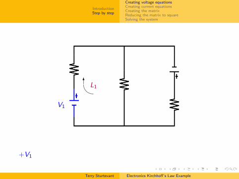
V1 is positive since we hit the negative terminal first.
Terry Sturtevant Electronics Kirchhoff’s Law Example
IntroductionStep by step
Creating voltage equationsCreating current equationsCreating the matrixReducing the matrix to squareSolving the system
L1
���?
R1 I1
6
V1
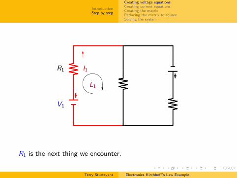
R1 is the next thing we encounter.
Terry Sturtevant Electronics Kirchhoff’s Law Example

IntroductionStep by step
Creating voltage equationsCreating current equationsCreating the matrixReducing the matrix to squareSolving the system
L1
���?
R1 I1
6
V1
I1R1 is negative since the loop direction matches the current direc-tion.
Terry Sturtevant Electronics Kirchhoff’s Law Example

IntroductionStep by step
Creating voltage equationsCreating current equationsCreating the matrixReducing the matrix to squareSolving the system
L1
���?
R1 I1
6
V1
R3 I3
6
R3 is next.
Terry Sturtevant Electronics Kirchhoff’s Law Example

IntroductionStep by step
Creating voltage equationsCreating current equationsCreating the matrixReducing the matrix to squareSolving the system
L1
���?
R1 I1
6
V1
R3 I3
6
I3R3 is positive since the loop direction opposes the current direction.
Terry Sturtevant Electronics Kirchhoff’s Law Example

IntroductionStep by step
Creating voltage equationsCreating current equationsCreating the matrixReducing the matrix to squareSolving the system
L1
@R
Start here
Terry Sturtevant Electronics Kirchhoff’s Law Example
IntroductionStep by step
Creating voltage equationsCreating current equationsCreating the matrixReducing the matrix to squareSolving the system
L1�6V1
+V1
Terry Sturtevant Electronics Kirchhoff’s Law Example

IntroductionStep by step
Creating voltage equationsCreating current equationsCreating the matrixReducing the matrix to squareSolving the system
L1
��-R1 I1
6
V1
+V1 − I1R1
Terry Sturtevant Electronics Kirchhoff’s Law Example

IntroductionStep by step
Creating voltage equationsCreating current equationsCreating the matrixReducing the matrix to squareSolving the system
L1
���?
R1 I1
6
V1
R3 I3
6
+V1 − I1R1 + I3R3
Terry Sturtevant Electronics Kirchhoff’s Law Example

IntroductionStep by step
Creating voltage equationsCreating current equationsCreating the matrixReducing the matrix to squareSolving the system
L1
���?
R1 I1
6
V1
R3 I3
6
+V1 − I1R1 + I3R3 = 0
Terry Sturtevant Electronics Kirchhoff’s Law Example

IntroductionStep by step
Creating voltage equationsCreating current equationsCreating the matrixReducing the matrix to squareSolving the system
Thus for the example above:
Loop 1 (starting at Node 1)
V1 − I1R1 + I3R3 = 0
Loop 2 (starting at Node 2)
V2 − I2R2 − I3R3 = 0
Loop 3 (starting at Node 1)
V1 − I1R1 + V2 − I2R2 = 0
Terry Sturtevant Electronics Kirchhoff’s Law Example
IntroductionStep by step
Creating voltage equationsCreating current equationsCreating the matrixReducing the matrix to squareSolving the system
Thus for the example above:Loop 1 (starting at Node 1)
V1 − I1R1 + I3R3 = 0
Loop 2 (starting at Node 2)
V2 − I2R2 − I3R3 = 0
Loop 3 (starting at Node 1)
V1 − I1R1 + V2 − I2R2 = 0
Terry Sturtevant Electronics Kirchhoff’s Law Example

IntroductionStep by step
Creating voltage equationsCreating current equationsCreating the matrixReducing the matrix to squareSolving the system
Making node equations
For each node:1 Currents coming into node are positive, others are negative.2 Set the sum of all of the contributions from 1 to zero.
Terry Sturtevant Electronics Kirchhoff’s Law Example

IntroductionStep by step
Creating voltage equationsCreating current equationsCreating the matrixReducing the matrix to squareSolving the system
Making node equations
For each node:
1 Currents coming into node are positive, others are negative.2 Set the sum of all of the contributions from 1 to zero.
Terry Sturtevant Electronics Kirchhoff’s Law Example

IntroductionStep by step
Creating voltage equationsCreating current equationsCreating the matrixReducing the matrix to squareSolving the system
Making node equations
For each node:1 Currents coming into node are positive, others are negative.
2 Set the sum of all of the contributions from 1 to zero.
Terry Sturtevant Electronics Kirchhoff’s Law Example

IntroductionStep by step
Creating voltage equationsCreating current equationsCreating the matrixReducing the matrix to squareSolving the system
Making node equations
For each node:1 Currents coming into node are positive, others are negative.2 Set the sum of all of the contributions from 1 to zero.
Terry Sturtevant Electronics Kirchhoff’s Law Example

IntroductionStep by step
Creating voltage equationsCreating current equationsCreating the matrixReducing the matrix to squareSolving the system
Here’s how the equation for Node 1 is created.
Terry Sturtevant Electronics Kirchhoff’s Law Example

IntroductionStep by step
Creating voltage equationsCreating current equationsCreating the matrixReducing the matrix to squareSolving the system
I1
6
I2?
I3
6
N1
Here is Node 1.
Terry Sturtevant Electronics Kirchhoff’s Law Example
IntroductionStep by step
Creating voltage equationsCreating current equationsCreating the matrixReducing the matrix to squareSolving the system
I1
6
I2?
I3
6
N1
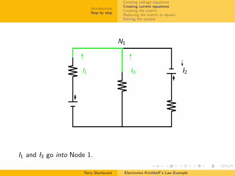
I1 and I3 go into Node 1.
Terry Sturtevant Electronics Kirchhoff’s Law Example
IntroductionStep by step
Creating voltage equationsCreating current equationsCreating the matrixReducing the matrix to squareSolving the system
I1
6
I2?
I3
6
N1
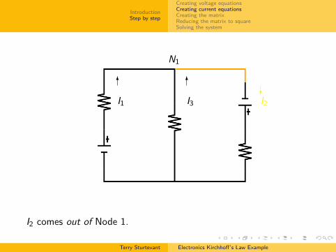
I2 comes out of Node 1.
Terry Sturtevant Electronics Kirchhoff’s Law Example

IntroductionStep by step
Creating voltage equationsCreating current equationsCreating the matrixReducing the matrix to squareSolving the system
I1
6
I2?
I3
6
N1
I1 + I3 = I2
Terry Sturtevant Electronics Kirchhoff’s Law Example
IntroductionStep by step
Creating voltage equationsCreating current equationsCreating the matrixReducing the matrix to squareSolving the system
I1
6
I2?
I3
6
N1
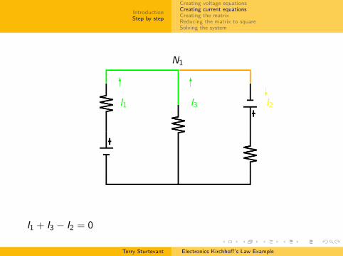
I1 + I3 − I2 = 0
Terry Sturtevant Electronics Kirchhoff’s Law Example

IntroductionStep by step
Creating voltage equationsCreating current equationsCreating the matrixReducing the matrix to squareSolving the system
Thus for the example above:
Node 1I2 − I3 − I1 = 0
Node 2I1 + I3 − I2 = 0
Terry Sturtevant Electronics Kirchhoff’s Law Example

IntroductionStep by step
Creating voltage equationsCreating current equationsCreating the matrixReducing the matrix to squareSolving the system
Thus for the example above:Node 1
I2 − I3 − I1 = 0
Node 2I1 + I3 − I2 = 0
Terry Sturtevant Electronics Kirchhoff’s Law Example

IntroductionStep by step
Creating voltage equationsCreating current equationsCreating the matrixReducing the matrix to squareSolving the system
Thus for the example above:Node 1
I2 − I3 − I1 = 0
Node 2I1 + I3 − I2 = 0
Terry Sturtevant Electronics Kirchhoff’s Law Example

IntroductionStep by step
Creating voltage equationsCreating current equationsCreating the matrixReducing the matrix to squareSolving the system
Set up a system of equations.
Thus for the example above:
Loop 1 : −I1R1 +I3R3 = −V1Loop 2 : −I2R2 −I3R3 = −V2Loop 3 : −I1R1 −I2R2 = −V1 − V2Node 1 : −I1 +I2 −I3 = 0Node 2 : +I1 −I2 +I3 = 0
Terry Sturtevant Electronics Kirchhoff’s Law Example

IntroductionStep by step
Creating voltage equationsCreating current equationsCreating the matrixReducing the matrix to squareSolving the system
Set up a system of equations. Thus for the example above:
Loop 1 : −I1R1 +I3R3 = −V1Loop 2 : −I2R2 −I3R3 = −V2Loop 3 : −I1R1 −I2R2 = −V1 − V2Node 1 : −I1 +I2 −I3 = 0Node 2 : +I1 −I2 +I3 = 0
Terry Sturtevant Electronics Kirchhoff’s Law Example

IntroductionStep by step
Creating voltage equationsCreating current equationsCreating the matrixReducing the matrix to squareSolving the system
Create matrices.
Thus for the example above:We can rewrite the above system in matrix form as
−R1 0 +R30 −R2 −R3−R1 −R2 0−1 +1 −1+1 −1 +1
I1
I2I3
=
−V1−V2
−V1 − V200
Terry Sturtevant Electronics Kirchhoff’s Law Example

IntroductionStep by step
Creating voltage equationsCreating current equationsCreating the matrixReducing the matrix to squareSolving the system
Create matrices.Thus for the example above:
We can rewrite the above system in matrix form as−R1 0 +R3
0 −R2 −R3−R1 −R2 0−1 +1 −1+1 −1 +1
I1
I2I3
=
−V1−V2
−V1 − V200
Terry Sturtevant Electronics Kirchhoff’s Law Example

IntroductionStep by step
Creating voltage equationsCreating current equationsCreating the matrixReducing the matrix to squareSolving the system
Create matrices.Thus for the example above:We can rewrite the above system in matrix form as
−R1 0 +R3
0 −R2 −R3−R1 −R2 0−1 +1 −1+1 −1 +1
I1
I2I3
=
−V1−V2
−V1 − V200
Terry Sturtevant Electronics Kirchhoff’s Law Example

IntroductionStep by step
Creating voltage equationsCreating current equationsCreating the matrixReducing the matrix to squareSolving the system
Create matrices.Thus for the example above:We can rewrite the above system in matrix form as
−R1 0 +R30 −R2 −R3−R1 −R2 0−1 +1 −1+1 −1 +1
I1
I2I3
=
−V1−V2
−V1 − V200
Terry Sturtevant Electronics Kirchhoff’s Law Example

IntroductionStep by step
Creating voltage equationsCreating current equationsCreating the matrixReducing the matrix to squareSolving the system
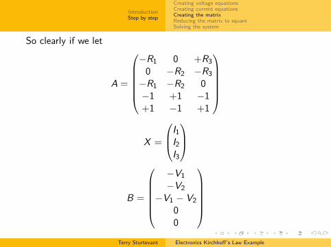
So clearly if we let
A =
−R1 0 +R3
0 −R2 −R3−R1 −R2 0−1 +1 −1+1 −1 +1
X =
I1I2I3
B =
−V1−V2
−V1 − V200
Terry Sturtevant Electronics Kirchhoff’s Law Example

IntroductionStep by step
Creating voltage equationsCreating current equationsCreating the matrixReducing the matrix to squareSolving the system
So clearly if we let
A =
−R1 0 +R3
0 −R2 −R3−R1 −R2 0−1 +1 −1+1 −1 +1
X =
I1I2I3
B =
−V1−V2
−V1 − V200
Terry Sturtevant Electronics Kirchhoff’s Law Example
IntroductionStep by step
Creating voltage equationsCreating current equationsCreating the matrixReducing the matrix to squareSolving the system
So clearly if we let
A =
−R1 0 +R3
0 −R2 −R3−R1 −R2 0−1 +1 −1+1 −1 +1
X =
I1I2I3
B =
−V1−V2
−V1 − V200
Terry Sturtevant Electronics Kirchhoff’s Law Example

IntroductionStep by step
Creating voltage equationsCreating current equationsCreating the matrixReducing the matrix to squareSolving the system
Then
AX = B
Terry Sturtevant Electronics Kirchhoff’s Law Example

IntroductionStep by step
Creating voltage equationsCreating current equationsCreating the matrixReducing the matrix to squareSolving the system
ThenAX = B
Terry Sturtevant Electronics Kirchhoff’s Law Example
IntroductionStep by step
Creating voltage equationsCreating current equationsCreating the matrixReducing the matrix to squareSolving the system
Reduce coefficient matrix to square, since it will not be invertibleotherwise.
Be sure to adjust the solution vector accordingly.
Terry Sturtevant Electronics Kirchhoff’s Law Example

IntroductionStep by step
Creating voltage equationsCreating current equationsCreating the matrixReducing the matrix to squareSolving the system
Reduce coefficient matrix to square, since it will not be invertibleotherwise. Be sure to adjust the solution vector accordingly.
Terry Sturtevant Electronics Kirchhoff’s Law Example

IntroductionStep by step
Creating voltage equationsCreating current equationsCreating the matrixReducing the matrix to squareSolving the system
A =
−R1 0 +R3
0 −R2 −R3−R1 −R2 0−1 +1 −1+1 −1 +1
Here’s the matrix
Terry Sturtevant Electronics Kirchhoff’s Law Example

IntroductionStep by step
Creating voltage equationsCreating current equationsCreating the matrixReducing the matrix to squareSolving the system
A =
−R1 0 +R3
0 −R2 −R3−R1 −R2 0−1 +1 −1+1 −1 +1
Notice row 1
Terry Sturtevant Electronics Kirchhoff’s Law Example

IntroductionStep by step
Creating voltage equationsCreating current equationsCreating the matrixReducing the matrix to squareSolving the system
A =
−R1 0 +R3
0 −R2 −R3−R1 −R2 0−1 +1 −1+1 −1 +1
Notice row 1 +row 2
Terry Sturtevant Electronics Kirchhoff’s Law Example

IntroductionStep by step
Creating voltage equationsCreating current equationsCreating the matrixReducing the matrix to squareSolving the system
A =
−R1 0 +R3
0 −R2 −R3−R1 −R2 0−1 +1 −1+1 −1 +1
Notice row 1 +row 2 equal row 3, so we can get rid of row 3
Terry Sturtevant Electronics Kirchhoff’s Law Example

IntroductionStep by step
Creating voltage equationsCreating current equationsCreating the matrixReducing the matrix to squareSolving the system
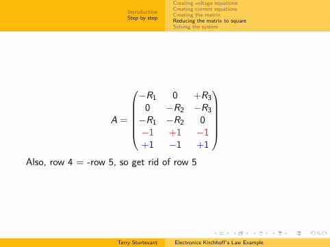
A =
−R1 0 +R3
0 −R2 −R3−R1 −R2 0−1 +1 −1+1 −1 +1
Also, row 4
Terry Sturtevant Electronics Kirchhoff’s Law Example
IntroductionStep by step
Creating voltage equationsCreating current equationsCreating the matrixReducing the matrix to squareSolving the system
A =
−R1 0 +R3
0 −R2 −R3−R1 −R2 0−1 +1 −1+1 −1 +1
Also, row 4 = -row 5, so get rid of row 5
Terry Sturtevant Electronics Kirchhoff’s Law Example

IntroductionStep by step
Creating voltage equationsCreating current equationsCreating the matrixReducing the matrix to squareSolving the system
So we are left with
A =
−R1 0 +R30 −R2 −R3−1 +1 −1
and
B =
−V1−V2
0
after adjustment
Terry Sturtevant Electronics Kirchhoff’s Law Example

IntroductionStep by step
Creating voltage equationsCreating current equationsCreating the matrixReducing the matrix to squareSolving the system
So we are left with
A =
−R1 0 +R30 −R2 −R3−1 +1 −1
and
B =
−V1−V2
0
after adjustment
Terry Sturtevant Electronics Kirchhoff’s Law Example

IntroductionStep by step
Creating voltage equationsCreating current equationsCreating the matrixReducing the matrix to squareSolving the system
NowX = A−1B
which gives
X =1
R2R1 + R2R3 + R1R3
R3V1 + R3V2 + R2V1R3V1 + R1V2 + R3V2
R1V2 − R2V1
Notice that, depending on the voltages involved, some of thecurrents could be negative. In this case, it simply means that theactual current goes in the opposite direction from what you hadchosen.
Terry Sturtevant Electronics Kirchhoff’s Law Example