Embed Size (px)
Citation preview

Reprinted with permission from August 2017 QST ARRL, the national association for Amateur Radio® www.arrl.org
overall operation away from the original design frequency. Now the wires resemble an M over a large U. This improve-ment slightly increased the size, but significantly improved overall operat-ing performance. This is the design chosen by Leo Shoemaker, K4KIO, of KIO Technology, and pub-lished in the March 2009 issue of QST.8
AssemblyUpon receiving my pack-ages, I opened them and inventoried the parts. I was pleasantly surprised to find all parts were there, the antenna was partly assembled, and all parts were neatly labeled within their own packaging. I was also pleased with the obvious quality of parts and construction and with the clarity of the instruc-
tions provided. Assembly would be very straightforward. Note: following instructions is always best.
KIO recommends painting the fiber-glass spreaders for protection from the Sun. Because we have a lot of sunshine down here, that was my first step. If I were taking the antenna on a DXpedition, I’d probably skip this step. I then gathered tools — a 7⁄16 wrench, a 3⁄16 nut driver for adjusting the hose clamps, pliers, and a small adjustable wrench.
The base plate and the L-shaped bot-
Reviewed by Bill Kennamer, [email protected]
A few years ago, we moved back to Arkansas, bringing a truckload of monoband Yagi antennas. After 3 years of searching, we finally found a suit-able location, but no house — so we started building. After 10 more years, the house is shaping up nicely, the antenna farm not so much. When we started building, my wife decreed that the house must be finished before any towers could be erected. However, as completion nears, we have jointly made the deci-sion that it’s just too much house for retired people to maintain, so we also decided that no perma-nent towers go up at this location.
Wanted: A Lightweight, Multiband BeamBecause I had a push-up TV mast available, and my wife was okay with that, I began to search for a suitable antenna. This antenna would have to be light, with a reasonably small footprint that could work on a TV mast. I also wanted coverage of 17 and 12 meters, in addition to the other bands. My search led me to two or three possibili-ties, and the one that seemed to be the
KIO Technology Broadband Hexagonal Beam Antenna
Bottom LineCompact and lightweight, the KIO
Technology Broadband Hexagonal Beam offers good performance on 20 – 6 meters.
best fit was the Broadband Hexagonal Beam from KIO Technology. I chose the five-band model (20, 17, 15, 12, and 10 meters) with an optional 6-meter kit and a BAL-8 balun kit. Within 5 days, it turned up at the house in two FedEx packages.
The original Hex-Beam was de-signed and manufactured by Traffie Technology in the late 1990s. Viewed from above, Traffie’s design resembled an M over a W in wire configuration. This antenna had a smaller footprint, but also a narrower bandwidth due to more folding of the element wires. Steve Hunt, G3TXQ, made enhance-ments to the original design that im-proved the bandwidth, thus improving
8L. Shoemaker, K4KIO, “Building a Five Band G3TXQ Broadband Hexagonal Beam,” QST, Mar. 2009, pp. 30 – 33.
QST® – Devoted entirely to Amateur Radio www.arrl.org Reprinted with permission from August 2017 QST
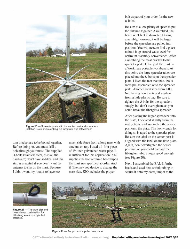
Figure 20 — Spreader plate with the center post and spreaders installed. Note studs sticking out for future wire attachment
Figure 21 — The Adel clip and hose clamp combination for attaching wires is simple but effective.
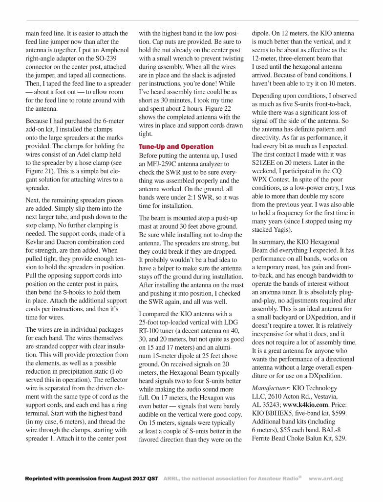
Figure 22 — Support cords pulled into place.
tom bracket are to be bolted together. Before doing so, you must drill a hole through your mast. The supplied U-bolts (stainless steel, as is all the hardware) don’t have saddles, and this step is essential if you don’t want the antenna to slip on the mast. Because I didn’t want my rotator to have too
much side force from a long mast with antenna on top, I used a 1-foot piece of 11⁄2-inch galvanized water pipe. It is sufficient for this application. KIO supplies the bolt required based upon the mast size specified at order. And if (like me) you decide to change the mast size, KIO includes the proper
bolt as part of your order for the new U-bolts.
Be sure to allow plenty of space to put the antenna together. Assembled, the beam is 21 feet in diameter. During assembly, however, it will be larger before the spreaders are pulled into position. You will need to find a place to hold it up around waist level for optimum assembly convenience. After assembling the mast bracket to the spreader plate, I clamped the mast on a Workmate portable workbench. At this point, the large spreader tubes are placed into the U-bolts on the spreader plate. I liked the fact that the U-bolts were pre-assembled onto the spreader plate. Another great idea from KIO! No chasing down nuts and washers from a little plastic bag. Be sure to tighten the U-bolts for the spreaders snugly, but don’t overtighten, as you could break the fiberglass spreader.
After placing the larger spreaders onto the plate, I deviated slightly from the instructions, and assembled the center post onto the plate. The hex wrench for doing so is taped to the spreader plate. Be sure the label on the center post is aligned with the label on the base plate. Again, don’t overtighten the center post nut, or you could damage the fiberglass tube. Snug is good enough (see Figure 20).
Next, I assembled the BAL-8 ferrite beads and used heat-shrink tubing to secure it onto my coax jumper to the
Reprinted with permission from August 2017 QST ARRL, the national association for Amateur Radio® www.arrl.org
main feed line. It is easier to attach the feed line jumper now than after the antenna is together. I put an Amphenol right-angle adapter on the SO-239 connector on the center post, attached the jumper, and taped all connections. Then, I taped the feed line to a spreader — about a foot out — to allow room for the feed line to rotate around with the antenna.
Because I had purchased the 6-meter add-on kit, I installed the clamps onto the large spreaders at the marks provided. The clamps for holding the wires consist of an Adel clamp held to the spreader by a hose clamp (see Figure 21). This is a simple but ele-gant solution for attaching wires to a spreader.
Next, the remaining spreaders pieces are added. Simply slip them into the next larger tube, and push down to the stop clamp. No further clamping is needed. The support cords, made of a Kevlar and Dacron combination cord for strength, are then added. When pulled tight, they provide enough ten-sion to hold the spreaders in position. Pull the opposing support cords into position on the center post in pairs, then bend the S-hooks to hold them in place. Attach the additional support cords per instructions, and then it’s time for wires.
The wires are in individual packages for each band. The wires themselves are stranded copper with clear insula-tion. This will provide protection from the elements, as well as a possible reduction in precipitation static (I ob-served this in operation). The reflector wire is separated from the driven ele-ment with the same type of cord as the support cords, and each end has a ring terminal. Start with the highest band (in my case, 6 meters), and thread the wire through the clamps, starting with spreader 1. Attach it to the center post
with the highest band in the low posi-tion. Cap nuts are provided. Be sure to hold the nut already on the center post with a small wrench to prevent twisting during assembly. When all the wires are in place and the slack is adjusted per instructions, you’re done! While I’ve heard assembly time could be as short as 30 minutes, I took my time and spent about 2 hours. Figure 22 shows the completed antenna with the wires in place and support cords drawn tight.
Tune-Up and OperationBefore putting the antenna up, I used an MFJ-259C antenna analyzer to check the SWR just to be sure every-thing was assembled properly and the antenna worked. On the ground, all bands were under 2:1 SWR, so it was time for installation.
The beam is mounted atop a push-up mast at around 30 feet above ground. Be sure while installing not to drop the antenna. The spreaders are strong, but they could break if they are dropped. It probably wouldn’t be a bad idea to have a helper to make sure the antenna stays off the ground during installation. After installing the antenna on the mast and pushing it into position, I checked the SWR again, and all was well.
I compared the KIO antenna with a 25-foot top-loaded vertical with LDG RT-100 tuner (a decent antenna on 40, 30, and 20 meters, but not quite as good on 15 and 17 meters) and an alumi-num 15-meter dipole at 25 feet above ground. On received signals on 20 meters, the Hexagonal Beam typically heard signals two to four S-units better while making the audio sound more full. On 17 meters, the Hexagon was even better — signals that were barely audible on the vertical were good copy. On 15 meters, signals were typically at least a couple of S-units better in the favored direction than they were on the
dipole. On 12 meters, the KIO antenna is much better than the vertical, and it seems to be about as effective as the 12-meter, three-element beam that I used until the hexagonal antenna arrived. Because of band conditions, I haven’t been able to try it on 10 meters.
Depending upon conditions, I observed as much as five S-units front-to-back, while there was a significant loss of signal off the side of the antenna. So the antenna has definite pattern and directivity. As far as performance, it had every bit as much as I expected. The first contact I made with it was S21ZEE on 20 meters. Later in the weekend, I participated in the CQ WPX Contest. In spite of the poor conditions, as a low-power entry, I was able to more than double my score from the previous year. I was also able to hold a frequency for the first time in many years (since I stopped using my stacked Yagis).
In summary, the KIO Hexagonal Beam did everything I expected. It has performance on all bands, works on a temporary mast, has gain and front-to-back, and has enough bandwidth to operate the bands of interest without an antenna tuner. It is absolutely plug-and-play, no adjustments required after assembly. This is an ideal antenna for a small backyard or DXpedition, and it doesn’t require a tower. It is relatively inexpensive for what it does, and it does not require a lot of assembly time. It is a great antenna for anyone who wants the performance of a directional antenna without a large overall expen-diture or for use on a DXpedition.
Manufacturer: KIO Technology LLC, 2610 Acton Rd., Vestavia, AL 35243; www.k4kio.com. Price: KIO BBHEX5, five-band kit, $599. Additional band kits (including 6 meters), $55 each band. BAL-8 Ferrite Bead Choke Balun Kit, $29.