Embed Size (px)
Citation preview

1
Abstract
A flapping quad-wing ornithopter is
modeled and analyzed to mimic flapping wing
biosystems to produce lift and thrust for forward
flight by considering the motion of a three-
dimensional rigid and thin quad-wing in
flapping and pitching motion with phase lag,
based on earlier analysis of bi-wing. Basic
Unsteady Aerodynamic Approach incorporating
salient features of viscous effect and leading-
edge suction is utilized. Parametric study is
carried out to reveal the aerodynamic
characteristics of flapping quad-wing
ornithopter flight and for comparative analysis
with various selected simple models in the
literature. A generic approach is followed to
understand and mimic the unsteady
aerodynamics of biosystem that can be adopted
in a simple and workable Quad-Wing-Micro-
Air-Vehicle (QVMAV) model. Analysis is
carried out by differentiating the pitching and
flapping motion phase-lag and studying its
respective contribution to the flight forces.
Further considerations are given to the
influence of the Strouhal number on the
propulsion generation. Results are discussed in
comparison with various selected simple models
in the literature, with a view to develop a
practical ornithopter model.
1 Introduction
The present work is a part of a series of work to
follow a generic approach to model the
kinematics and aerodynamics of flapping wing
ornithopter, by focusing on a flapping quad-
wing ornithopter modeled and analyzed to
mimic flapping wing biosystems to produce lift
and thrust for forward flight. To this end
considerations are given to the motion of a
three-dimensional rigid and thin quad-wing in
flapping and pitching motion with phase lag
following earlier analysis of bi-wing model.
Basic Unsteady Aerodynamic Approach
incorporating salient features of viscous effect
and leading-edge suction will be utilized.
Parametric study is carried out to reveal the
aerodynamic characteristics of flapping quad-
wing ornithopter flight characteristics and for
comparative analysis with various selected
simple models in the literature, in an effort to
develop a simple flapping quad-wing
ornithopter model, as exemplified in Fig. 1. A
generic approach is followed to understand and
mimic the unsteady aerodynamics of biosystem
that can be adopted in a simple and workable
Quad-Wing-Micro-Air-Vehicle (QVMAV)
model.
The most distinctive characteristic of
flapping wing motion of ornithopters and
entomopters flight is the wing kinematics.
Based on Ellington’s study [1- 3], the kinematic
of flight produced by the generic wing (semi-
elliptical wing) can be classified into the
inclined stroke plane, where the resultant force
produced by the wing can be separated into
vertical and horizontal components, which are
lift, thrust and drag, respectively throughout the
up-stroke and down-stroke cycle; the inclined
stroke plane, where a large horizontal thrust
component will be produced; and the vertical
stroke plane.
KINEMATIC AND UNSTEADY AERODYNAMIC MODELLING OF FLAPPING BI- AND QUAD-WING
ORNITHOPTER
Harijono Djojodihardjo, Muhammad Anas Abd Bari
Universiti Putra Malaysia, 43400 Serdang, Selangor Darul Ehsan, Malaysia
Keywords: Bi-Wing Ornithopter, Flapping Wing Aerodynamics, Micro Air Vehicle, Quad-Wing
Ornithopter, Unsteady Aerodynamics

HARIJONO DJOJODIHARDJO & MUHAMMAD ANAS ABD BARI
2
Fig. 1: Upstroke and downstroke motion of dragonfly
(Adapted from [17]).
Motivated by flying biosystems, flight
engineering has been initiated since hundreds of
years ago and has gradually grown from the
time of Leonardo Da Vinci to Otto Lilienthal’s
gliders, to modern aircraft technologies and
present flapping flight research. Recent interest
in the latter has grown significantly particularly
for small flight vehicles (or Micro-Air-Vehicles)
with very small payload carrying capabilities to
allow remote sensing missions hazardous as
well as confined areas. Some of these vehicles
may have a typical wingspan of 15 cm, with a
weight restriction of less than 100 g (Ho et al,
[4]). Perhaps the most comprehensive account
of insect flight or entomopter to date is given by
Weis-Fogh [5], Ellington [1-3], Shyy et al [6-7],
Dickinson et al [8], Żbikowski [9] and Ansari et
al [10], while one of the first successful attempts
to develop birdlike flapping flight was made by
DeLaurier [11]. Although our interest in
developing a mathematical and experimental
model is on more or less rigid quad wing
ornithopter, it is also motivated by the fact that
insect and hummingbirds have lightweight,
flexible wings that undergo large deformations
while flapping, which can increase the lift of
flapping wings (Rosenfeld [12]). It will be of
good interest how wing flexibility can be later
on adopted. The flapping wing designs have
been created with varied success, for forward or
hover mode, but not both, based on observations
of hummingbirds and bats (Nicholson et al
[13]). According to Maybury and Lehmann
[14], the dragonfly has the capability to shift
flight modes simply by varying the phase lag
between its fore and hind wings. With that
observation, a quad-winged flapping system
could be conceived as the simplest mechanism
that has the capabilities to shift between flight
modes [13]. In one of the recent works in
developing quad flapping wing micro air
vehicle, Ratti [15] has theoretically shown that a
flight vehicle with four flapping wings has 50%
higher efficiency than that with two flapping
wings. Inspired by the flight of a dragonfly,
Prosser [16] analyzed, developed and
demonstrated a Quad-Wing Micro Air Vehicle
(QW-MAV) which can produce higher
aerodynamic performance and energy
efficiency, and increased payload capacity
compared to a conventional (flapping wing)
MAV (BW-MAV). However, to develop a
generic model of flapping wing ornithopter, Bi-
Wing ornithopter will first be reviewed and
developed, and then extended to quad-wing
ornithopter.
The image displayed in Fig. 1 exhibit a
dragonfly, which will later be imitated to take
advantage of the quad-wing kinematic and
aerodynamic interactions, in the effort of
improving the performance of the ornithopter to
be developed. Fig. 1 also schematically exhibits
the flapping motion of the quad-wing dragonfly,
as studied by Wang and Russell [17]. Within
such backdrop, a generic approach is followed
to understand and mimic the unsteady
aerodynamics of Biosystem that can be adopted
in the present bi-wing FW-MAV and quad-wing
QWMAV, following our previous attempt to
develop pterosaur-like ornithopter to produce
lift and thrust for forward flight as a simple and
workable ornithopter flight model [18]. At the
present stage, such model will not take into
account the more involved leading edge vortex
and wake penetration exhibited by insect flight
[1-10].
2 Kinematics of Flapping Wing Motion
The flapping wing motion of ornithopters and
entomopters can be generally grouped in three
classes, based on the kinematics of the wing
motion and mechanism of forces generation; the
horizontal stroke plane, inclined stroke plane
and vertical stroke plane [5]. As a result of these

3
KINEMATIC AND UNSTEADY AERODYNAMIC MODELLING OF FLAPPING BI- AND QUAD-WING ORNITHOPTER
kinematics, the aerodynamics
associated with insect flight are
also very different from those met
in conventional fixed- and rotary-
wing air-vehicle or even bird flight
[10]. Based on Ellington’s study [1-
3], the kinematics of flight
produced by the generic wing
(semi-elliptical wing) can be
classified into the inclined stroke
plane, where the resultant force produced by the
wing can be separated into vertical and
horizontal components, which are lift, thrust and
drag, respectively, throughout the up-stroke and
down-stroke cycle; the inclined stroke plane,
where a large horizontal thrust component will
be produced; and the vertical stroke plane.
Insect wings are elegant, impressive and
instructive to be considered in the development
of small-scale engineering. They are deformable
airfoils whose shape is actively controlled by
the wingbase articulation while the wing area is
subject to inertial, elastic and aerodynamic
forces.
3 Theoretical Development of the Generic
Aerodynamics of Flapping Wings
Following the frame of thought elaborated in the
previous section, several generic flying
biosystem wing planforms are chosen as
baseline geometries for the ornithopter.
Referring to the eagle wing and for convenience
of baseline analysis, the semi elliptical wing
(shown in Fig. 2) is selected for the current bi-
wing baseline study, which will also be utilized
for the quad-wing study.
In the present work, analytical approaches of
quasi-steady and unsteady model are carefully
evaluated in order to deal with the aerodynamic
problem. In agreement with the quasi-steady
model, it is observed and can be assumed that
the flapping frequencies are sufficiently slow
that shed wake effects are negligible, as in
pterosaur and medium- to large-sized birds so
that the unsteady approach attempts to model
the wake like hummingbird and insects can be
deferred to the refinement stage of the work.
The present aerodynamic approach is
synthesized using basic foundations that may
exhibit the generic contributions of the motion
elements of the bio-inspired bi-wing and quad-
wing air vehicle characteristics. These are the
strip theory and thin wing aerodynamic
approach [19], Jones modified Theodorsen
unsteady aerodynamics [20, 11], incorporation
of leading edge suction [21, 22], and Jones’
modified Theodorsen approach which
incorporates Garrick’s leading edge suction.
The computation of lift and thrust generated by
pitching and flapping motion of three-
dimensional rigid wing is conducted in a
structured approach using strip theory and
Jones’ modified Theodorsen approach without
camber, leading edge suction and post-stall
behavior. Later, the computational model will
take into account certain physical parameters
that can be identified via observations and
established results of various researchers.
Lifting-surface theory [23-26] may later be
incorporated. In the present work, unsteady
aerodynamics of a flapping wing using a
modified strip theory approach as a
simplification of DeLaurier’s[11] approach is
utilized without post-stall behavior. The
computational logic in the present work is
summarized in the Flow-Chart exhibited in Fig.
3.
To obtain insight into the mechanism of lift
and thrust generation, Djojodihardjo and Ramli
[27-29] and Djojodihardjo and Bari [30-31]
analyzed the wing flapping motion by looking
into the individual contribution of the pitching,
flapping and coupled pitching-flapping to the
generation of the aerodynamic forces. Also the
influence of the variation of the forward speed,
flapping frequency and pitch-flap phase lag has
been analyzed. Such approach will also be
followed here through further scrutiny of the
motion elements. The generic procedure is
Fig. 2: A generic semi-elliptical ornithopter wing planform adopted from
eagle-wing planform
(a) Top view and outline of an eagle wing (b) The present Baseline Generic Wing Planform.

HARIJONO DJOJODIHARDJO & MUHAMMAD ANAS ABD BARI
4
Fig. 3: Ornithopter Flapping Wing Aerodynamics
Computational Scheme
Fig. 4: (a)Forces on section of the wing. (b),(c),(d)Flapping and Pitching motion of
flapping wing.
synthesized from the pitching-flapping motion
of rigid wing developed by DeLaurier [11],
taking into account unsteady aerodynamics of
Theodorsen [19], Jones [20], and Garrick [22].
The flapping motion of the wing is
distinguished into three distinct motions with
respect to the three axes; these are: a) Flapping,
which is up and down plunging motion of the
wing; b) Feathering is the pitching motion of
wing and can vary along the span; c) Lead-lag,
which is in-plane lateral movement of wing, as
incorporated in Fig. 4. The lead-lag motion
could be interpreted to apply to the phase lag
between pitching and flapping motion, while the
fore-and-aft movement can be associated with
the orientation of the stroke plane. The degree
of freedom of the motion is also depicted in Fig.
4. The flapping angle β varies as a
sinusoidal function and pitching angle θ
are given by the following equations.
0( ) cost t
(1)
0( ) sin( )
dyt t
B
(2)
where θ0 and βo indicate maximum value
for each variables, is the lag between
pitching and flapping angle and y is the
distance along the span of the wing.
As a baseline, by referring to eq. (1) and
eq. (2), β is considered to vary following
a cosine function while θ a sine function.
Leading edge suction is included
following the analysis of Polhamus [32]
which has been taken into consideration
by DeLaurier’s approximation [11] and
Harmon [33].
Three dimensional
effects will later be
introduced by using
Scherer’s modified
Theodorsen-Jones Lift
Deficiency Factor [34]. To
account for the unsteady
effects, Theodorsen
unsteady aerodynamics
[19] and its three
dimensional version by
Jones [20] have been
incorporated. Further
refinement is made to
improve accuracy. Thin
airfoil approximation based on Prandtl’s lifting
line theory, i.e. that the circulation is acting on
the quarter-chord and the downwash and
dominant airflow is calculated at the three-
quarter chord point, is also adopted for each
strip.
In the present analysis no linear variation of
the wing’s dynamic twist is assumed for
simplification and instructiveness. However, in
principle, such additional requirements can
easily be added due to the linearity assumption.
Assuming small angle approximation, for the
plunging displacement or heaving of the wing,
the flapping displacement h is given by
h y
(3)
5
KINEMATIC AND UNSTEADY AERODYNAMIC MODELLING OF FLAPPING BI- AND QUAD-WING ORNITHOPTER
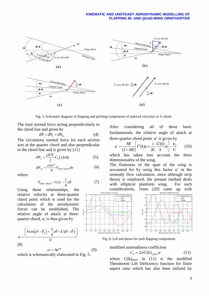
Fig. 5: Schematic diagram of flapping and pitching components of induced velocities at ¾ chord.
The total normal force acting perpendicularly to
the chord line and given by
c ncdN dN dN (4)
The circulatory normal force for each section
acts at the quarter chord and also perpendicular
to the chord line and is given by [11]
( )
2c n
UVdN C y cdy
(5)
2
4nc mid chord
cdN V dy
(6)
where
1
4mid chordV U c (7)
Using these relationships, the
relative velocity at three-quarter
chord point which is used for the
calculation of the aerodynamic
forces can be established. The
relative angle of attack at three-
quarter chord, α, is then given by
3
cos ( )4
ah c U
U
(8)
i tAe (9)
which is schematically elaborated in Fig. 5.
After considering all of these basic
fundamentals, the relative angle of attack at
three-quarter chord point α’ is given by
' ( ) ( )
(2 ) 2
owAR c G kF k
AR U k U
(10)
which has taken into account the three
dimensionality of the wing.
The finiteness of the span of the wing is
accounted for by using this factor α’ in the
unsteady flow calculation, since although strip
theory is employed, the present method deals
with elliptical planform wing. For such
considerations, Jones [20] came up with
modified unsteadiness coefficient
2 ( )n jonesC C k
(11)
where C(k)jones in (11) is the modified
Theodorsen Lift Deficiency function for finite
aspect ratio which has also been utilized by
Fig. 6: Lift and thrust for each flapping components

HARIJONO DJOJODIHARDJO & MUHAMMAD ANAS ABD BARI
6
DeLaurier in his approach. Accordingly,
C(k)jones is a complex function; therefore it is
more convenient to use Scherer’s [19,20]
formulation which takes the following form
( )( )
(2 AR)jones
AR C kC k
(12)
( ) ( ) ( )C k F k iG k (13) C(k), F(k) and G(k) relate to the well-known
Theodorsen function [19,20] which are
functions of reduced frequency, k. In addition,
in present study, the interpretation that the real
part of C(k) contributes only to the lift whereas
the imaginary part for the thrust is adopted. This
interpretation follows the methodological
philosophy of Theodorsen and Garrick [26,39]
and the classical unsteady aerodynamics. Using
Complex Analysis, the unsteady lift is expressed
as [22]:
2 ( )L b C k Q (14)
where Q is given by i tQ e . Then,
substitution Q into eq. (14) gives
2 ( ) i tL b C k e (15)
In the Complex Analysis of Theodorsen,
Garrick, the convenience of the analysis is to
associate the Imaginary part of (14) and (15)
with the Lift [22, 35]. The details are elaborated
as follows. The reduced frequency is defined as
bk
, or
b tt ks
b
. Assuming
sinusoidal motion
cos sini te t i t (16)
or
cos sini te ks i ks
(17)
Combining (13 ) and (15), one obtains:
2 ( ) ( ) cos sin L b F k iG k ks i ks (18)
Note that
1
2 2 2( ) ( ) ( ) ( ) ( )
CC k k F k iG k F k G k (19)
After algebraic manipulation, Eq. (18) reduces
to
( )cos( )cos ( )sin( )sin2 .
( ) cos( )sin sin( )cos
C C
C
k ks k ksL b I P
i k ks ks
(20)
and the imaginary parts of the above equation is
( )sink ks C (21)
Therefore:
1
2 2 12( )
2 ( ) ( ) sin tan( )
L
G kb F k G k ks
F k
(22)
For consistency with the strip theory, the
downwash for untwisted planform wing is given
by (Anderson [36])
02( )
2
ow
U AR
(23)
From Fig. 5(c), the flow velocity which includes
the downwash and wing’s motion relative to
free-stream velocity, V can be formulated as
1
2 22 1cos sin '
2
V
U h U c (24)
where the third and fourth terms are acting at
the three-quarter chord point. The apparent mass
effect (momentum transferred by accelerating
air to the wing) for the section, is perpendicular
to the wing, and acts at mid chord, and can be
calculated as [11]
2 1( )
4 4nc
cdN U c dy
(25)
The term 1
4U c is mid-chord normal
velocity’s time rate of change due to the motion
of the wing.
Apart from normal forces, chordwise forces
are also generated due to sectional circulation
distribution as in Fig. 6(a). The total chordwise
force, dFx is accumulated by three forces which
are leading edge suction, force due to camber,
and chordwise friction drag due to viscosity
effect. All of these forces acting along and
parallel to the chord line as in the Fig. 4(a).
x s camber fdF dT dD dD (26)
where Garrick’s [26,39] expression for leading
edge suction, dTs is
12
4 2s s
c UVdT cdy
U
(27)
and [11]
2 ( )
2camber o
UVdD cdy
(28)

7
KINEMATIC AND UNSTEADY AERODYNAMIC MODELLING OF FLAPPING BI- AND QUAD-WING ORNITHOPTER
Fig. 7: Variation of Lift (a) and Thrust (b) with phase
lag between Pitching and Flapping
21
2f x fdD V C cdy
(29)
According to the potential theory, the leading
edge suction for most airfoils is predicted to be
less that 100% due to viscosity effect, hence the
efficiency term ηs is introduced for dTs. The
normal 2D force, dN and 2D chordwise force,
dFx for each section is of the is also changes its
direction at every instant during flapping. These
forces in the vertical and horizontal directions
will be resolved into those perpendicular and
parallel to the free-stream velocity, respectively.
The resulting vertical and horizontal
components of the forces is then given by
cos sinxdL dN dF
(30)
cos dNsinxdT dF (31)
These expressions are then integrated along the
semi span, b/2 in order to obtain a three
dimensional lift for each wing
/2
2
0
b
DL L dy (32)
/2
2
0
b
DT T dy
(33)
4 The influence of the phase-lag between
pitching and flapping motion and the
individual motion component on the flight
performance
A parametric study is carried out to
investigate the influence of the phase lag
between pitching and flapping motion to the
generation of lift and thrust. As exhibited in
Fig. 7, the optimum lift and thrust can also
be obtained by appropriate choice of this
phase lag. From this study, it is observed that
the lift always increases with phase lag angle
between pitching and flapping motion, and it
reaches its maximum value when the phase
lag angle, = 3π/8. The thrust also exhibits
a similar behavior.
Another study is carried out to assess the
influence of other flapping wing motion
parameters, such as flapping frequency, wing
angle of incidence and the effect of total
flapping angle, to the flight performance
desired. Fig. 8 (a) and (b) show the
contribution of individual motion component
to the lift and thrust including the result
using the lifting surface method result
obtained by La Mantia and Dabnichki [37]
and Spectral Method of Ou and Jameson
[38], respectively.
5 Modeling and Parametric Study of the
Influence of Leading Edge Vortex (LEV) on
Bi-wing Flapping Motion Aerodynamics
To study the influence of a leading edge vortex
(LEV) on the flapping flight performance, the
oscillatory motion of bi-wing flapping system is
simulated by assuming discontinuous motion,
by considering the discontinuity to be
contributed by instant vortex shedding at the
leading edge. To serve as a baseline, the
development of the simulation is based on the
following rationale:
Table 1: Forces for prevous and tailored scheme

HARIJONO DJOJODIHARDJO & MUHAMMAD ANAS ABD BARI
8
Fig. 9: Lift and thrust due to simulated LEV effect
Fig. 8: The contribution of individual motion component to the lift
(upper) and thrust (lower); comparison with Lifting surface result of
La Mantia and Dabnichki [37] and Spectral Method of Ou and
Jameson [38] exhibit similar qualitative behavior
LEV is assumed to occur as part of the
pitching motion
LEV is created due to sudden downstroke
movement of the leading edge; from
biological and performance optimization
reason, LEV is assumed not to be created
during the upstroke.
LEV is created during the sudden change of
motion which is assumed to take place
within a fraction of each stroke. For
illustration, without loss of generalities, that
fraction is assumed to be in the order of
10%.
Since the lift and thrust are the two
components of the aerodynamic force and
thrust of the flapping wing, then this
idealized LEV is acting in the same fashion
for both lift and thrust.
These assumptions are only applied to the
pitch motion without considering skin
friction, three-dimensional effect and
Fig. 10: (a) Drag producing vortex street; (b)
Thrust producing vortex street. Adapted from [40]

9
KINEMATIC AND UNSTEADY AERODYNAMIC MODELLING OF FLAPPING BI- AND QUAD-WING ORNITHOPTER
Table 1: Average lift and thrust
leading edge suction. The effect of these
three flapping motion components, from
physical reasoning, should be superposed to
the resulting discontinuous pitching motion
to obtain the total lift and thrust per cycle
similar to the procedure followed in the
absence of LEV.
Without going through the detail, such
procedure is followed to mimic the influence of
LEV in a biosystem, to reach the objective of
enhancing performance as intrinsic control in
biosystem and to allow simple simulation in a
mechanized ornithopter. Then a parametric
study is carried out to simulate discontinuous
motion that will produce better lift and thrust.
The result are exhibited in Fig. 9a, which
indicates that by performing such discontinuous
pitching oscillation, better lift contribution to
the flapping aerodynamic performance is
produced compared to the original continuous
one. However, no significant thrust
contribution is indicated (Fig. 9b).
6 Aerodynamic Forces and Strouhal
Number Relationship in Bi-Wing
Von Karman and Burgers [39] offered the
first theoretical explanation of drag or thrust
production based on the resulting vortex
street (i.e., the placement and orientation of
the wake vortex elements). With respect to
flapping airfoil, Jones and Platzer [40]
demonstrates that vortex streets
characteristic of drag production have a row
of vortices of clockwise rotation above the
symmetry plane, and a row of vortices of
counter-clockwise rotation below the
symmetry plane, as exhibited in shown in
Fig. 10a. For an airfoil plunging at a low
Strouhal number (k = 3.6, h = 0.08, St =
0.29), the vortices induce a velocity or
momentum deficit on the centerline
indicative of drag, and the wake wavelength,
, defined here as the distance between
vortex centers of same rotation, is shorter
than the wavelength predicted by linear
theory, l.t. = 2π/k, due to the production of
drag.
Oscillating the airfoil more energetically the
vortex street shown in Fig. 10b is generated (k =
3.0, h =0.20, St = 0.60), which produces thrust.
In the present work, the Strouhal number is
defined as
0 0 0h h hbSt k
U b U b
(34)
For small insects, Yu and Ma [41] noted that
the flapping Strouhal number St 1.0, i.e. the
reduced frequency k = 2St 2, and noted
Lighthill's findings, that k = 0.5 is the upper
limit of applying the quasi-steady assumption.
Pennycuick [42] experimentally derived the
correlation of the wing-beat frequency for
flapping flight to the body mass, wingspan,
wing area and the wing moment of inertia. For
birds with the body mass ranging from 20g to
nearly 5kg the wingbeat frequency is correlated
by the following formula:
HARIJONO DJOJODIHARDJO & MUHAMMAD ANAS ABD BARI
10
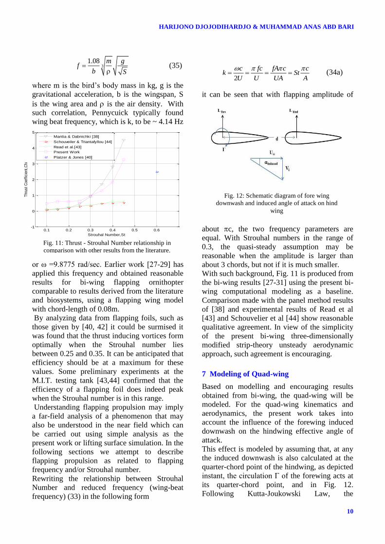
Fig. 12: Schematic diagram of fore wing
downwash and induced angle of attack on hind
wing
31.08 m g
fb S
(35)
where m is the bird’s body mass in kg, g is the
gravitational acceleration, b is the wingspan, S
is the wing area and is the air density. With
such correlation, Pennycuick typically found
wing beat frequency, which is k, to be ~ 4.14 Hz
or ω =9.8775 rad/sec. Earlier work [27-29] has
applied this frequency and obtained reasonable
results for bi-wing flapping ornithopter
comparable to results derived from the literature
and biosystems, using a flapping wing model
with chord-length of 0.08m.
By analyzing data from flapping foils, such as
those given by [40, 42] it could be surmised it
was found that the thrust inducing vortices form
optimally when the Strouhal number lies
between 0.25 and 0.35. It can be anticipated that
efficiency should be at a maximum for these
values. Some preliminary experiments at the
M.I.T. testing tank [43,44] confirmed that the
efficiency of a flapping foil does indeed peak
when the Strouhal number is in this range.
Understanding flapping propulsion may imply
a far-field analysis of a phenomenon that may
also be understood in the near field which can
be carried out using simple analysis as the
present work or lifting surface simulation. In the
following sections we attempt to describe
flapping propulsion as related to flapping
frequency and/or Strouhal number.
Rewriting the relationship between Strouhal
Number and reduced frequency (wing-beat
frequency) (33) in the following form
2
c fc fA c ck St
U U UA A
(34a)
it can be seen that with flapping amplitude of
about c, the two frequency parameters are
equal. With Strouhal numbers in the range of
0.3, the quasi-steady assumption may be
reasonable when the amplitude is larger than
about 3 chords, but not if it is much smaller.
With such background, Fig. 11 is produced from
the bi-wing results [27-31] using the present bi-
wing computational modeling as a baseline.
Comparison made with the panel method results
of [38] and experimental results of Read et al
[43] and Schouvelier et al [44] show reasonable
qualitative agreement. In view of the simplicity
of the present bi-wing three-dimensionally
modified strip-theory unsteady aerodynamic
approach, such agreement is encouraging.
7 Modeling of Quad-wing
Based on modelling and encouraging results
obtained from bi-wing, the quad-wing will be
modeled. For the quad-wing kinematics and
aerodynamics, the present work takes into
account the influence of the forewing induced
downwash on the hindwing effective angle of
attack.
This effect is modeled by assuming that, at any
the induced downwash is also calculated at the
quarter-chord point of the hindwing, as depicted
instant, the circulation Γ of the forewing acts at
its quarter-chord point, and in Fig. 12.
Following Kutta-Joukowski Law, the
Fig. 11: Thrust - Strouhal Number relationship in
comparison with other results from the literature.
0.1 0.2 0.3 0.4 0.5 0.6-1
0
1
2
3
4
5
Strouhal Number,St
Thr
ust
Coe
ffic
ient
,Cfx
Mantia & Dabnichki [38]
Schouveiler & Triantafyllou [44]
Read et al.[43]
Present Work
Platzer & Jones [40]
11
KINEMATIC AND UNSTEADY AERODYNAMIC MODELLING OF FLAPPING BI- AND QUAD-WING ORNITHOPTER
Table 3: Quad-Wing Parametric study results
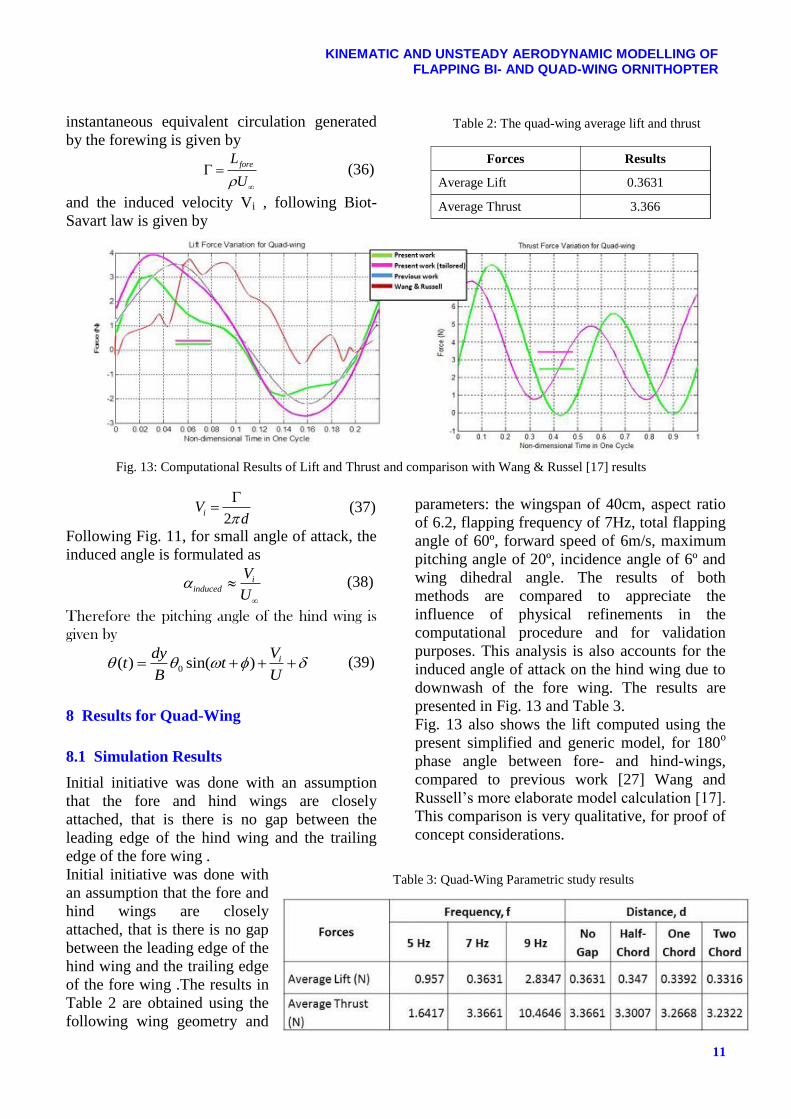
Forces Results
Average Lift 0.3631
Average Thrust 3.366
Table 2: The quad-wing average lift and thrust
instantaneous equivalent circulation generated
by the forewing is given by
foreL
U (36)
and the induced velocity Vi , following Biot-
Savart law is given by
2iV
d
(37)
Following Fig. 11, for small angle of attack, the
induced angle is formulated as
induce
id
V
U
(38)
Therefore the pitching angle of the hind wing is
given by
0( ) sin( ) iVdy
t tB U
(39)
8 Results for Quad-Wing
8.1 Simulation Results
Initial initiative was done with an assumption
that the fore and hind wings are closely
attached, that is there is no gap between the
leading edge of the hind wing and the trailing
edge of the fore wing .
Initial initiative was done with
an assumption that the fore and
hind wings are closely
attached, that is there is no gap
between the leading edge of the
hind wing and the trailing edge
of the fore wing .The results in
Table 2 are obtained using the
following wing geometry and
parameters: the wingspan of 40cm, aspect ratio
of 6.2, flapping frequency of 7Hz, total flapping
angle of 60º, forward speed of 6m/s, maximum
pitching angle of 20º, incidence angle of 6º and
wing dihedral angle. The results of both
methods are compared to appreciate the
influence of physical refinements in the
computational procedure and for validation
purposes. This analysis is also accounts for the
induced angle of attack on the hind wing due to
downwash of the fore wing. The results are
presented in Fig. 13 and Table 3.
Fig. 13 also shows the lift computed using the
present simplified and generic model, for 180o
phase angle between fore- and hind-wings,
compared to previous work [27] Wang and
Russell’s more elaborate model calculation [17].
This comparison is very qualitative, for proof of
concept considerations.
Fig. 13: Computational Results of Lift and Thrust and comparison with Wang & Russel [17] results

HARIJONO DJOJODIHARDJO & MUHAMMAD ANAS ABD BARI
12
8.2 Variation of Oscillatory Articulation of
the Quad-Wing
Following the procedure and parametric study
carried out for bi-wing ornithopter [27-31], the
present study also addresses the flapping
kinematics accordingly, by taking into
considerations what has been learned from bi-
wing
parametric
study. The
forewing and
hindwing are
arranged in
tandem without
gap, so that the
leading edge of
the hindwing
touches the
trailing edge of
the forewing, and
they are moving
simultaneously. The pitching motion of both
forewing and hindwing moves sinusoidally,
while the flapping motion of both is varied
following sine, negative cosine and cosine. The
results, as exhibited in Fig. 14, shows that the
synchronous sinusoidal pitching and flapping
produce the maximum amplitude as well as
average values of lift and thrust. These results
also indicate one variation only of such
oscillatory articulation possibilities that could be
further tailored to meet certain objectives.
8.3 Parametric Study for Quad-Wing
A parametric study is carried out to assess the
influence of certain flapping wing motion
parameters to the flight performance desired.
The study considers the following parameters:
the effect of forward speed, the effect of
flapping frequency, the effect of lag angle, the
effect of distance between fore and hind wing
and the effect of the total flapping angle. The
results are exhibited in Fig. 15 and table 3. In
general, the sensitivity of the bi-wing and quad-
wing towards these parameters are comparable.
Interesting results are exhibited by Table 1
where the combination of pitch and flap of both
fore and hind wings are varied.
Results obtained as exhibited in next section
show the lift produced for various scenarios
involving phase combinations between flapping
and pitching motions of the individual fore- and
hind-wings. Table 1 summarizes the average
forces per cycle for the selected scenarios.
A deduction can be made from the results from
Table 1 that the phase lag of π/4 produces the
maximum lift and thrust among the others.
However further
analysis to
optimize the
combination of
these parameters
is still under
progress.
9 Conclusion
The present work
has been
performed to
assess the effect Fig. 14: Lift and thrust for quad-wing for each flapping motion components
Fig. 15: Lift and Thrust generated by Fore and Hind wing

13
KINEMATIC AND UNSTEADY AERODYNAMIC MODELLING OF FLAPPING BI- AND QUAD-WING ORNITHOPTER
of flapping-pitching motion with pitch-flap
phase lag in the flight of ornithopter. In this
conjunction, a computational model has been
considered, and a generic computational method
has been adopted, utilizing strip theory and two-
dimensional unsteady aerodynamic theory of
Theodorsen with modifications to account for
three-dimensional and viscous effects and
leading edge suction. The study is carried out on
semi-elliptical wing planforms. For the quad-
wing ornithopter, at the present stage, the
simplified computational model adopted
verified the gain in lift obtained as compared to
bi-wing flapping ornithopter, in particular by the
possibility of varying the phase lag between the
flapping and pitching motion of individual wing
as well as between the fore- and hind-wings. A
structured approach has been followed to assess
the effect of different design parameters on lift
and thrust of an ornithopter, as well as the
individual contribution of the component of
motion. These results lend support to the
utilization of the generic modeling adopted in
the synthesis of a flight model, although more
refined approach should be developed. Various
physical elements could be considered to
develop ornithopter kinematic and aerodynamic
modeling, as well as using more refined
aerodynamic computation, such as CFD or
lifting surface methods. In retrospect, a generic
physical and computational model based on
simple kinematics and basic aerodynamics of a
flapping-wing ornithopter has been
demonstrated to be capable of revealing its basic
characteristics and can be utilized for further
development of a flapping-wing MAV.
Application of the present kinematic,
aerodynamic and computational approaches
shed some light on some of the salient
aerodynamic performance of the quad-wing
ornithopter.
The results have been compared and
validated with other literatures within similar
unsteady aerodynamic approach and general
physical data, and within the physical
assumptions limitations; encouraging qualitative
agreements or better have been indicated, which
meet the proof of concept objectives of the
present work. For the bi-wing flapping
ornithopter, judging from lift per unit span, the
present flapping-wing model performance is
comparable to those studied by Byl [37] and
Harmon [32].The analysis and simulation by
splitting the flapping and pitching motion shows
that: (a) The lift is dominantly produced by the
pitching motion, since the relative airflow effect
prevailed along 75% of the chord length. (b)
The thrust is dominated by flapping motion (c)
Phase-lag could be utilized to obtain optimum
lift and thrust for each wing configurations.
Acknowledgment
The authors would like to thank Universiti Putra
Malaysia (UPM) for granting Research
University Grant Scheme (RUGS) Project Code:
9378200, under which the present research is
carried out.
References
[1] Ellington CP, The Aerodynamics of Hovering Insect
Flight, III. Kinematics, Phil. Trans. R. Soc. London
B, 305, pp 41-78, 1984.
[2] Ellington CP, The Novel Aerodynamics of Insect
Flight: Applications to Micro-Air Vehicles, The
Journal of Experimental Biology 202, pp 3439–3448,
1999.
[3] Ellington CP, The Aerodynamics of Hovering Insect
Flight, I, Quasi-Steady Analysis,” Phil.Trans. of
Roy.Soc.London, B, Bio.Sci., Vol 35, No 1122, Feb
1984.
[4] Ho S, Nassef H, Pornsinsirirak N, Tai YC and Ho
CM, Unsteady Aerodynamics and Flow Control for
Flapping Wing Flyers, Progress in Aerospace
Sciences 39, pp 635–681, 2003.
[5] Weis-Fogh T, Quick Estimates of Flight Fitness in
Hovering Animals, Including Novel Mechanisms for
Lift Production. Journal of Experimental Biology 59,
pp 169–230, 1973.
[6] Shyy W, Berg M and Ljungqvist D, Flapping and
Flexible Wings for Biological and Micro Air
Vehicles, Progress in Aerospace Sciences, Vol. 35:
pp 455-505, 1999.
[7] Shyy W, Aono H, Chimakurthi S K, Trizila P, Kang
C-K, Cesnik C E S and Li H. Recent Progress in
Flapping Wing Aerodynamics and Aeroelasticity,
Progress in Aerospace Science, 2010.
[8] Dickinson M H, Lehmann F O and Sane S P, Wing
Rotation and the Aerodynamic Basis of Insect Flight,
Science 284, pp 1954, 1999.
[9] Żbikowski R, On Aerodynamic Modelling of an
Insect-like Flapping Wing in hover for Micro Air
Vehicles, Phil. Trans. R. Soc. Lond. A 360, pp 273-
390, 2002.

HARIJONO DJOJODIHARDJO & MUHAMMAD ANAS ABD BARI
14
[10] Ansari S A, Żbikowski R and Knowles K,
Aerodynamic Modelling of Insect-like Flapping
Flight for Micro Air Vehicles, Progress in Aerospace
Sciences 42, pp 129–172, 2006.
[11] DeLaurier J D, An Aerodynamic Model for Flapping
Wing Flight, The Aeronautical Journal of the Royal
Aeronautical Society, pp. 125-130, 1993.
[12] Rosenfeld N C, An Analytical Investigation of
Flapping Wing Structures for MAV, Ph.D. Thesis,
University of Maryland, 2011.
[13] Nicholson B, Page S, Dong H and Slater J, Design of
a Flapping Quad-Winged Micro Air Vehicle, AIAA-
4337, 2007.
[14] Maybury W J and Lehmann F-O, The Fluid
Dynamics of Flight Control by Kinematic Phase Lag
Variation Between Two Robotic Insect Wings,
Journal of Experimental Biology, Vol. 207, pp 4707-
4726, 2004.
[15] Ratti J, QV-The Quad Winged, Energy Efficient, Six
degree of Freedom Capable Micro Air Vehicle, PhD
thesis, Georgia Institute of Technology, 2011.
[16] Prosser D T, Flapping Wing Design for a Dragon-fly
like MAV, M.Sc. Thesis, Rochester Institute of
Technology, 2011.
[17] Wang Z J and Russell D, Effect of Forewing and
Hindwing Interactions on Aerodynamic Forces and
Power in Hovering Dragonfly Flight, Physical
Review Letters 99, 148101, 2007.
[18] Lentink D, Jongerius S R and Bradshaw N L, The
Scalable Design of Flapping Micro-Air Vehicles
Inspired by Insect Flight, Flying Insects and Robots,
pp 185-205, 2010.
[19] Theodorsen T, General Theory of Aerodynamic
Instability and the Mechanism of Flutter, NACA
Report No.496, 1949.
[20] Jones R T, The Unsteady Lift of a Wing of Finite
Aspect Ratio, NACA Report 681, 1940.
[21] Kuethe A M, Chow C-Y, The Finite Wing,
Foundations of Aerodynamics, 4th ed, John Wiley,
New York, pp145-164, 1986.
[22] Garrick I E, Propulsion of a Flapping and Oscillating
Aerofoil, NACA Report No.567, 1936.
[23] Ashley H, Landahl M T and Widnall S E, New
Directions in Lifting Surface Theory, AIAA journal,
3, No.1, 1965.
[24] Albano A and Rodden W P, A doublet-lattice method
for calculating lift distributions on oscillating
surfaces in subsonic flows, AIAA Journal, Vol. 7, No.
2, pp. 279-285, 1969.
[25] Djojodihardjo H and Widnall S E, A numerical
method for the calculation of nonlinear, unsteady
lifting potential flow problems, 1969,
AIAA Journal, Vol. 7, No. 2, pp. 2001-2009, 1969
[26] Murua J, Palacios R, and Graham, J M R,
Applications of the Unsteady Vortex-Lattice Method
in Aircraft Aeroelasticity and Flight Dynamics
Preprint submitted to Progress in Aerospace Sciences
August 1, 2012
[27] Djojodihardjo H and Ramli ASS, Kinematic And
Unsteady Aerodynamic Modelling, Numerical
Simulation And Parametric Study Of Flapping Wing
Ornithopter, Proceedings, International Forum on
Aeroelasticity and Structural Dynamics, Bristol,
2013.
[28] Djojodihardjo H and Ramli A S S, Generic and
Parametric Study of the Aerodynamic Characteristics
of Flapping Wing Micro-Air-Vehicle, Applied Mech.
and Materials, Trans Tech Publications,
Switzerland,Vol.225, pp 18-25, 2012.
[29] Djojodihardjo H and Ramli, A S S, Kinematic and
Aerodynamic Modeling of Flapping Wing
Ornithopter, Procedia Engineering (Elsevier), Vol.
50, 2012, pp 848-863, 2012.
[30] Djojodihardjo H and Bari M A A , Further
Development of the Kinematic and Aerodynamic
Modeling and Analysis of Flapping Wing
Ornithopter from Basic Principles, Submitted to
Aerotech Conference 2014, October 29-30 2014,
Kuala Lumpur, Malaysia
[31] Djojodihardjo H and Bari M A A, Kinematic and
Unsteady Aerodynamic Modelling of Flapping Wing.
Submitted for publication, 2014 .
[32] Polhamus E C, A Concept Of The Vortex Lift Of
Sharp-Edge Delta Wings Based On A Leading-Edge-
Suction Analogy, NASA TN D-3767, 1966.
[33] Harmon R L, Aerodynamic Modelling of a Flapping
Membrane Wing Using Motion Tracking
Experiments, M.Sc. Thesis, University of Maryland,
2008.
[34] Scherer J O, Experimental and Theoretical
Investigation of Large Amplitude Oscillating Foil
Propulsion Systems, Hydronautics, Laurel, Md,
December 1968.
[35] Garrick I E, On Some Reciprocal Relations in the
Theory of Nonstationary Flows, NACA Report 629,
1938.
[36] Anderson J D, Fundamentals of Aerodynamics,
fourth ed., McGraw-Hill, New York.2004.
[37] Ou, K. and Jameson, A., Towards Computational
Flapping Wing Aerodynamics of Realistic
Configurations using Spectral Difference Method,
AIAA 2011-3068, 20th AIAA CFD Conference,
2011
[38] La Mantia, M. and Dabnichki, P., Unsteady Panel
Method for Oscillating Foils, in Advances in BE
Tech., Gatmiri, Sellier, Aliabadi, BETEQ-2006-
part2, 2006
[39] Von Karman, T. and Burgers, J. M.,, General
Aerodynamic Theory - Perfect Fluids," Division E,
Vol. II, Aerodynamic Theory, Ed. Durand, W. F.,
1943, p.
[40] Jones, K.D. and Platzer, M.F., Numerical
Computation of Flapping-Wing Propulsion and
Power Extraction, AIAA−97−0826-NPS Lib.
[41] Yu, Tong, Ma, An Analytic Approach To Theoretical
Modeling of Highly Unsteady Viscous Flow Excited
By Wing Flapping in Small Insects, Acta
Mech.Sinica, V19, N6, Dec 2003

15
KINEMATIC AND UNSTEADY AERODYNAMIC MODELLING OF FLAPPING BI- AND QUAD-WING ORNITHOPTER
[42] Pennycuick C J, Predicting Wingbeat Frequency and
Wavelength of Birds, The Journal of Experimental
Biology150, pp 171 – 85, 1990.
[43] Read, Hover and Triantafyllou, Forces on Oscillating
Foils for Propulsion and Maneuvering, Journal of
Fluids and Structures, 17 (1), pp 163-183, 2003.
[44] Schouveiler H and Triantafyllou, Performance of
Flapping Foil Propulsion, Journal of Fluids and
Structures, 20 (7), pp 949-959, 2005.
[45] Byl K, A Passive Dynamic Approach for Flapping
Wing Micro Aerial Vehicle Control, ASME Dynamic
Systems and Controls Conference, 2010.
http://www.ece.ucsb.edu/~katiebyl/papers/Byl10
_DSCC.pdf
[46] Norberg, U.M., Hovering Flight of Plecotus auritus,
L. Bijdr. Dierk 40, Proc.2nd
int. Bat.Res, Conf., pp
62-66, 1970.
[47] Tedrake R, Jackowski Z, Cory R, Roberts J W and
Hoburg W, Learning to Fly like a Bird,
Communications of the ACM, 2009.
[48] Altshuler D L, Dudley R, Ellington C P,
Aerodynamic Forces of Revolving Hummingbird
Wings and Wing Models, J. Zool, Land., 264, pp
327-332, 2004.
[49] Kesel A B, Aerodynamic Characteristics of
Dragonfly Wing Sections Compared with Technical
Airfoils, J. Exp. Biol. 203,pp 3125-3135, 2000.
[50] Tucker V A, Gliding Birds: The Effect Of Variable
Wing Span, J. Exp. Biology, 133, 1987.
[51] Mueller D, Bruck H A and Gupta, S K, Measurement
of Thrust and Lift Forces Associated with Drag of
Compliant Flapping Wing for Micro Air Vehicles
using a New Test Stand Design, Experimental
Mechanics 50, pp 725–735, 2009.
[52] Deng X and Hu Z, Wing-wing Interactions in
Dragonfly Flight, A Publication of Ine-Web.Org,
10.2417/1200811.1269, 2008.
[53] Jones K D and Platzer M F, Numerical Computation
of Flapping-Wing Propulsion And Power Extraction,
AIAA−97−0826-NPS Lib.
[54] Triantafyllou M S and Triantafyllou GS, An efficient
swimming machine, Scientific American; Vol. 272
Issue 3, web.mit.edu, 1995.
[55] Wang J, Dissecting Insect Flight, Ann.Rev.Fl.Mech.
2005, 37, pp 183-210.
[56] Jones and Platzer, On the Use of Vortex Flows for
the Propulsion of Micro-Air & Sea Vehicles, MP-
069(I)-(SYA)-40
[57] Xu B and Wang J, Passive wing pitch reversal in
insect flight, JFM 2007, Vol. 591,pp 321-327
[58] Phillips N and Knowles K, Formation of the Leading-
edge Vortex and Spanwise Flow on an Insect-like
Flapping-wing throughout a Flapping Half Cycle,
https://dspace.lib.cranfield.ac.uk/bitstream/1826/.../ma
nuscript%20final.p
[59] Warrick D R, Tobalske B W and Powers D R, Lift
production in the hovering hummingbird, Proc. R.
Soc. B 276, pp 3747–3752, 2009
Contact Author Email Address
Corresponding Author:
Harijono Djojodihardjo. Professor, Aerospace
Engineering Department, Faculty of
Engineering, Universiti Putra Malaysia, 43400
UPM Serdang, Selangor Darul Ehsan, Malaysia.
Email address:
Copyright Statement
The authors confirm that they, and/or their company or
organization, hold copyright on all of the original material
included in this paper. The authors also confirm that they
have obtained permission, from the copyright holder of
any third party material included in this paper, to publish
it as part of their paper. The authors confirm that they
give permission, or have obtained permission from the
copyright holder of this paper, for the publication and
distribution of this paper as part of the ICAS2014
proceedings or as individual off-prints from the
proceedings.


![Dynamics and flight control of a flapping- wing robotic ... · aerodynamics of flapping-wing flight [8,13–15]. Despite having achieved stable flight, the flapping-wing robot in](https://img.dokumen.tips/doc/110x75/5e232a06436fd7265e4f446b/dynamics-and-flight-control-of-a-flapping-wing-robotic-aerodynamics-of-flapping-wing.jpg)