Embed Size (px)
Citation preview

RDR 200GX/DP Weather Radar System
The information contained herein is RADTEC. Any copying
or reproduction of this document in any form and/or disclosure to other parties Rev 7/6/09
without the express written consent of Radtec Engineering, Inc. is strictly prohibited Page 1
RDR-200GX/DP Weather Radar Systems
SHMU Dual Polarity Radar Site RDR-200GX
Kosice, Slovakia Antenna/Transmitter/Receiver
Lockheed-Martin RDR-200GX Radtec Offset Feed Antenna
Weather Radar Systems IInnnnoovvaattiivvee TTeecchhnnoollooggyy
AAffffoorrddaabbllee PPrroovveenn

RDR 200GX/DP Weather Radar System
The information contained herein is RADTEC. Any copying
or reproduction of this document in any form and/or disclosure to other parties
without the express written consent of Radtec Engineering, Inc. is strictly prohibited
Rev 2013
Page 2
Table Of Contents
RDR RADAR ADVANTAGES ................................................................................................................... 3
THE RDR FAMILY OF RADAR SYSTEMS ........................................................................................... 5
SENSITIVITY VERSUS RANGE .............................................................................................................. 6
TRANSMITTER .......................................................................................................................................... 7
PRECISION OFFSET FEED ANTENNA ................................................................................................. 8
LOW SIDE LOBE ENERGY REDUCES GROUND/SEA CLUTTER ........................................................................... 9
RADOME .................................................................................................................................................... 11
RADOME TECHNOLOGY AND DUAL POLARITY .............................................................................................. 12
ADVANCED LIGHTNING PROTECTION PROGRAM ....................................................................................... 12
DUAL POLARITY RDR-200GX/DP ........................................................................................................14
CONVENTIONAL PRECIPITATION ESTIMATION ALGORITHMS: SHORTCOMINGS FOR OPERATIONAL USE ..........16
SIMULTANEOUS TRANSMISSION, PARALLEL RECEPTION ........................................................................... 16
RADTEC’S IMPLEMENTATION OF DUAL POLARITY RADAR ............................................................................. 16
RDR RADAR TECHNICAL CHARACTERISTICS ............................................................................. 20

RDR 200GX/DP Weather Radar System
The information contained herein is RADTEC. Any copying
or reproduction of this document in any form and/or disclosure to other parties
without the express written consent of Radtec Engineering, Inc. is strictly prohibited
Rev 2013
Page 3
RDR Radar Advantages n Technology- The RDR family of radar systems uses the most up to date
technology available for magnetron radar systems, including;
• Stable Design Concept
• Coaxial magnetron
• Fully solid state linear IGBT modulator
• Integrated low noise receiver front end
• Digital receiver and signal processor
e Company with complete in-house radar design and manufacturing
capabilities
• Assures product integrity and reliability throughout the product’s life
• Assures complete system integration and performance verification
• Easily facilitates performance upgrades and enhancements
• Assures affordable technical support and protection against obsolescence
throughout the product’s life
• ISO 9001-2000 certified
Performance- The low noise integrated receiver front end, and stable
linear IGBT solid state modulator, combined with a digital receiver, provide
frequency and phase stability approaching that of a fully coherent Klystron.
The benefit is more accurate velocity data, better ground clutter cancellation,
and superior dual polarity operation.
The RDR-200GX has a maximum PRF of 5000 pulses per second, more than
double that of many other weather radars. The high PRF means accurate Doppler
measurement of high wind velocities - double that of many radars.
Ground Clutter- Velocity based clutter filters, in conjunction with a
precision COHO phase locked to the magnetron provide 40 dB or better clutter
rejection. An optional offset feed antenna provides 35 dB or better side lobe
suppression for additional ground clutter rejection (most ground clutter is due to
antenna side lobes).
The offset feed antenna substantially reduces ground clutter, which assures
reliable detection and warning of wind shear conditions even in the Terminal
Control Area, with the clutter inherent in an airport location.
The combination of DFT velocity processing with the offset feed antenna and
linear IGBT modulator provides the most effective and reliable state-of-the-art
clutter suppression available today- under virtually all operating conditions.

RDR 200GX/DP Weather Radar System
The information contained herein is RADTEC. Any copying
or reproduction of this document in any form and/or disclosure to other parties
without the express written consent of Radtec Engineering, Inc. is strictly prohibited
Rev 2013
Page 4
Reliable- The RDR family of radars use a stable well proven design, with a
minimum number of components, and are fully solid state (with the exception
of the magnetron tube).
Operating Cost- The stable, well proven design, with standard
components wherever possible, adds up to a system with very low operating
costs. In addition, wherever possible, all RDR models share components within
the X, C-band and S-band product line. This commonality leads to initial cost
savings, as well savings in the on-going cost of support, training, maintenance,
etc.
Capabilities Protect Investment- Modular design allows
upgrading to meet future requirements, protecting today’s investment:
• Antenna
8 ft. (2.4 m) offset feed antenna for superior ground clutter rejection, 0.9°
beam width, 45 dB gain, 35 dB first side lobe suppression (one way, single
polarity)
• Optional hydrological analysis software provides full analysis product
generation capability including volume scan products and hydro -
meteorological rainfall analysis.
• Optional aviation support software provides product generation, detection,
time of arrival forecast and warning capabilities for wind shear, microbursts,
gust fronts, etc.
• Multiple radar networking provides expansion of coverage area, status/control
and processing for all radars at a central location, unattended operation of
radars in remote locations
• Overlay and underlay capability allows easy selection/inclusion of a wide
range of maps, satellite imagery, etc. on radar images
• Optional dual polarity operation provides improved accuracy of rainfall
measurement and measurement of precipitation type (rain, hail, snow, graupel,
etc.).

RDR 200GX/DP Weather Radar System
The information contained herein is RADTEC. Any copying
or reproduction of this document in any form and/or disclosure to other parties
without the express written consent of Radtec Engineering, Inc. is strictly prohibited
Rev 2013
Page 5
The RDR Family Of Radar Systems
Dehydrator
Radar Control
Processor
(RCP)
Signal Processor
Servo Amplifier
Transmitter
Waveguide Test Points
“Conventional” RDR-200GX/DP
Transmitter/Receiver
“Package” RDR-200GX System
For Mounting Inside Radome
The RDR family of radar systems is made up of a number of models which can be
configured to meet virtually any weather radar requirement.
RDR-200GXDP: The RDR-200GX/DP is an advanced, digital Doppler
weather radar designed to provide reliable precipitation
measurement in a high clutter environment. It features an offset
feed antenna to minimize ground clutter, and optional dual
polarity operation for maximum rainfall measurement accuracy
and precipitation classification. It includes the REI-DSP digital
receiver and signal processor which provides PPI and volume
scan data and analysis products of scientific quality and
accuracy.

RDR 200GX/DP Weather Radar System
The information contained herein is RADTEC. Any copying
or reproduction of this document in any form and/or disclosure to other parties
without the express written consent of Radtec Engineering, Inc. is strictly prohibited
Rev 2013
Page 6
Sensitivity versus Range
The following graph indicates the sensitivity of the RDR-200GX/DP magnetron radar out
to 200 km range. These sensitivity calculations assume a 2.4 m antenna with 0.9° beam
width, and a 4.5 µsecond pulse width.
Sensitivity versus Range
0.00
-10.00
0 50 100 150 200 250 300
-20.00
-30.00
-40.00
-50.00
-60.00
Radtec
RDR200GX
2.4 m Ant
4.5µs P/W
Single Pol
Radtec
RDR200GX
2.4 m Ant
4.5µs P/W
Dual Pol
-70.00
R a nge (km)
Sensitivity (dBZ) vs. Range For RDR-200GX/DP 200 kW X-Band Radar
Proven Reliability, Low Risk of the RDR Family
Commercial-off-the-shelf availability - very low technical risk.
Coaxial magnetron technology - cost effective, proven reliability.
Solid state Linear IGBT modulator - reliable, no thyratrons to replace; accurate pulse stability.
Virtually maintenance free pedestal - Long life AC servo motors, low mass antenna
Integrated front end receiver- minimizes complex setup and calibration adjustments
Digital signal processor - more accurate velocity data for superior ground clutter rejection
Available options - assure ability to meet future needs, protecting today’s investment

RDR 200GX/DP Weather Radar System
The information contained herein is RADTEC. Any copying
or reproduction of this document in any form and/or disclosure to other parties
without the express written consent of Radtec Engineering, Inc. is strictly prohibited
Rev 2013
Page 7
Transmitter
Accurate Doppler velocity data requires that the radar’s operating frequency and phase be
extremely stable. When pulses are received, any change in frequency/phase is assumed
to be Doppler shift due to velocity of the target precipitation. If the change is the result
of instability in the transmitter, the signal processor has no way to detect which part of
the change is due to the target velocity, and which is due to transmitter instability, thus,
velocity data is less accurate.
One of the major advantages of a Doppler radar is the ability to use velocity based clutter
filters. This means that targets with zero velocity are assumed to be clutter, and filtered
out. To do this effectively, the radar must have very accurate velocity data.
In the RDR radar’s receiver and digital signal processor-receiver, the measurement of the
magnetron burst is used for phase locking (Digital COHO) and for Automatic Frequency
Control (AFC) of the Stable Local Oscillator (STALO). The stability of the transmitter
and accuracy of the burst phase measurement permit 40 dB or better of ground clutter
cancellation in the velocity based clutter filters.
In a Doppler radar, the maximum range and the maximum velocity that can be measured
are related to the Pulse Repetition Frequency (PRF). Longer ranges require lower PRF’s;
higher velocities require higher PRF’s. Thus, there is a trade-off between velocity and
range. This is sometimes referred to as the Doppler Dilemma.
The RDR-200GX/DP solid state linear IGBT modulator permits selecting a PRF’s from
500 to 5000 pulses per second. This permits adjusting the PRF to the optimum value for
the existing conditions. In addition, pulse staggered velocity unfolding is available with
2/3, 3/4 and 4/5 ratio.
Linear IGBT modulator
has fully programmable pulse widths and pulse rates. No fixed time
constants (Pulse Forming Network, charged delay
line, etc.) are used.
The only limitation on pulse width/rate combinations is the magnetron duty cycle. Pulse width/rate changes are automatically checked to prevent exceeding the maximum duty cycle.

RDR 200GX/DP Weather Radar System
The information contained herein is RADTEC. Any copying
or reproduction of this document in any form and/or disclosure to other parties
without the express written consent of Radtec Engineering, Inc. is strictly prohibited
Rev 2013
Page 8
Vm
ax (
m/s
)
100.00
10.00
1.00
10.00 100.00 1000.00
Rmax (km)
Chart of RDR-200GX/DP - PRF (pulse rate) versus Rmax (maximum unambiguous range) and Vmax (maximum unambiguous velocity).
Precision Offset Feed Antenna
Offset Feed Antenna
Superior ground clutter rejection
d on RDR-200GX/DP
Parabolic reflector
Precision offset feed
2.4 m (8 ft) or 4.3 m ( 14 ft )
45 dB gain
width
First side lobes
-35dBc (one way single polarity)
-30dBc (one way dual polarity)
Rigid composite materials
Low mass
Reduced driveline stress Longlife AC servomotors
Offset Feed Antenna

The information contained herein is RADTEC. Any copying
or reproduction of this document in any form and/or disclosure to other parties
without the express written consent of Radtec Engineering, Inc. is strictly prohibited
Rev 2013
Page 9
RDR 200GX/DP Weather Radar System
Severe Ground Clutter Typical Of A Large City The Same Image With An Offset Feed
Antenna And Velocity Based Clutter Filtering
Low Side Lobe Energy Reduces Ground/Sea Clutter
Antennas with low side lobe energy avoid ground clutter. Moving ground clutter, such as produced by vehicles and waves cannot be filtered out, thus avoiding moving clutter is extremely important. The Radtec precision offset feed antenna simply avoids most ground clutter.
The feedhorn support struts and waveguide do not interfere with the beam of the
exclusive Radtec precision offset feed antenna. Thus its first side lobes are typically -
35dBc (one way).
The performance of a parabolic antenna is also determined by the accuracy of its shape.
The accurate shape of a Radtec offset feed antenna reflector is inherent in the reflector;
not dependent on supporting structure. The light weight, very rigid composite materials,
and precision manufacturing, assure that the Radtec offset feed antenna will retain its
accurate shape, and, therefore, design level performance, throughout its life.

The information contained herein is RADTEC. Any copying
or reproduction of this document in any form and/or disclosure to other parties
without the express written consent of Radtec Engineering, Inc. is strictly prohibited
Rev 2013
Page 10
RDR 200GX/DP Weather Radar System
Conventional center feed antennas place the feedhorn and its support struts in the main beam. The interference with the main beam produces side lobes which cause reflections from clutter targets.
Offset Feed Antenna Components

The information contained herein is RADTEC. Any copying
or reproduction of this document in any form and/or disclosure to other parties
without the express written consent of Radtec Engineering, Inc. is strictly prohibited
Rev 2013
Page 11
RDR 200GX/DP Weather Radar System
Radome
(12 ft.) for 2.4 m offset feed
antenna (22 ft ) for 4.3 m
me
0.3 dB for A-sandwich radome
230 Km/hr (138 mph) wind survival
for undamaged radome
-50° C to +70°C
Hydrophobic surface
90% transmission when wet
Radtec laminated radome
RDR radomes are moisture resistant and corrosion proof. Undamaged radomes have
withstood winds in excess of 200 mph. Many similar radomes are in use in installations
worldwide, many with over 20 years of successful service.

The information contained herein is RADTEC. Any copying
or reproduction of this document in any form and/or disclosure to other parties
without the express written consent of Radtec Engineering, Inc. is strictly prohibited
Rev 2013
Page 12
RDR 200GX/DP Weather Radar System
Radome Technology And Dual Polarity
Both the laminated and A-sandwich radomes are truly spherical not composed of
segmented, flat panels. The pedestal design is such that the center of rotation for both
azimuth and elevation is placed at the center of the radome, resulting in a symmetrical
electrical signal path length for all antenna motions.
When used in dual polarization mode, a major cause of discrepancies between the
horizontal and vertical polarization planes is caused by a radome frame, especially a
metal frame. MFG Galileo A-sandwich radomes have seams, but no frame. The seam
has very good RF performance. The RF transmission of the seam is very close to that of
the rest of the radome. Additional details on MFG Galileo A-sandwich radome
construction and performance are available in a Radtec technical exhibit.
Advanced Lightning Protection Program
Lightning is the single most frequent cause of damage to weather radar systems. The risk
of damage to the radar system can be significantly reduced through certain design and
construction features of the radar and its installation:
• Radome lightning protection system- The radome and antenna are particularly
vulnerable to lightning strikes. Adequate protection is required to reduce the
potential for damage to the radar from lightning strikes on the radome and
antenna.
Radtec offers MFG Galileo’s lightning protection system, which is compliant
with both the “rolling sphere” concept defined in the National Fire Protection
Association (NFPA) standard 780, and the US Federal Aviation Administration
(FAA) standard FAA-STD-019C which covers lightning protection for ground
based aviation related equipment and facilities in the United States.
• Adequate earth grounding- Radtec recommends an earth ground for the radar
system of not more that one ohm ground resistance.
• Adequate isolation of the radar system from incoming power and communication
circuits
The following diagrams illustrate a lightning protection system described by NFPA
standard 780.

The information contained herein is RADTEC. Any copying
or reproduction of this document in any form and/or disclosure to other parties
without the express written consent of Radtec Engineering, Inc. is strictly prohibited
Rev 2013
Page 13
RDR 200GX/DP Weather Radar System
Lightning Protection
“Rolling Sphere” Area defined by National Fire Protection Association Standard 780
Typical Radtec Lightning Protection Configuration Per NFPA Std. 780
Provides 3-dimensional lightning protection around the radome.

The information contained herein is RADTEC. Any copying
or reproduction of this document in any form and/or disclosure to other parties
without the express written consent of Radtec Engineering, Inc. is strictly prohibited
Rev 2013
Page 14
RDR 200GX/DP Weather Radar System
Dual Polarity RDR-200GX/DP
Dual polarity capability is available as an option on Radtec radars. The option includes
all required features for the antenna, transmitter, receiver, signal processor and the
required processing software. The radar is still capable of providing all normal
reflectivity and velocity products in addition to the dual polarity products.
Radtec radars with the dual polarity hardware option currently support the following dual
polarity data products:
ZDR- Differential Reflectivity
KDP- Specific Differential Phase Shift
DP- Differential Phase Shift
hv-
LDR-
Co-polar Correlation Coherency Coefficient
Linear Depolarization Ratio
Rainfall rate and accumulation
Precipitation Classification (Rain, Drizzle, Snow, Small Hail, Large Hail,
Graupel)
With traditional weather radar technology, the radar can only measure the total reflection.
The total reflection is a function of the size, number and phase (rain, snow, hail, etc.) of
precipitation particles (hydrometeors). Thus determining the actual amount of liquid in
the precipitation, or detecting a specific type of precipitation, such as hail, from only a
radar image becomes at best an estimate which may be subject to large errors. Doppler
adds the ability to measure velocity, which greatly enhances the radar’s ability to detect
certain types of severe weather.
A significant amount of research has been done to determine how to get more
precipitation information using a radar system. Much of that research has been focused
on radar systems that have the ability to control the polarization angle of the transmitted
signal and to analyze reflectivity data at specified polarization angles. This is called a
polarimetric (dual polarity) radar. Polarimetric techniques provide accurate rainfall
measurement at all locations within the radar’s coverage area, and accurate measurement
of specific types of precipitation within a storm cell. These advances are likely to make
as big an improvement in radar based weather forecasting over Doppler radar as the
addition of Doppler capability did over conventional weather radar.
Horizontally and vertically polarized
pulses transmitted simultaneously with
equal amplitude.
Transmitted Pulses
Reflected
Pulses
Reflected pulses with amplitude of
horizontal and vertical reflections
proportional to shape of target
Small Drop - nearly spherical, weak
reflections, H & V nearly equal
Medium Drop - slightly flattened,
medium strength reflections, H > V
Large Drop - significantly flattened,
strong reflections, H >> V
Small hailstone - tumbling randomly,
strong reflections, H & V nearly equal
Large hailstone - predominant dimension
vertical, strong reflections, V > H

The information contained herein is RADTEC. Any copying
or reproduction of this document in any form and/or disclosure to other parties
without the express written consent of Radtec Engineering, Inc. is strictly prohibited
Rev 2013
Page 15
RDR 200GX/DP Weather Radar System
ZDR (differential reflectivity) is one of the simplest polarimetric techniques. For ZDR, the
radar transmits pulses with horizontal and vertical polarization, either simultaneously, or
on alternating pulses. The differences in amplitude between the horizontally and
vertically polarized reflections are analyzed to extract more information about the
precipitation.
Small raindrops are nearly spherical and reflect horizontally and vertically polarized
signals nearly equally. As raindrops become larger, they tend to flatten into oblate
spheroids. This flattening is the result of air flow pressure on the bottom of the drop as it
falls. Therefore, drops will tend to fall with the widest dimension of their shape aligned
horizontally. The widest dimension (horizontal) will reflect horizontally polarized
signals more strongly than the narrower dimension (vertical). Thus, the difference
between the horizontally and vertically polarized reflections can provide an estimate of
the size of the raindrops. This technique is referred to as differential reflectivity or ZDR.
ZDR has been demonstrated to provide ability to differentiate between hail and other
types of precipitation. Small hail stones tend to be relatively symmetrical and tumble
randomly as they fall. Therefore, there is little difference in amplitude between
horizontally and vertically polarized reflections from hailstones. Large hail stones tend
to be assymmetrical and fall with the longest dimension vertical (prolate), thus reflecting
the vertically polarized signal more strongly. As a result, an area showing high dBZ
reflectivity with a ZDR value of 3 or 4 dB is likely to be heavy rain. If the ZDR value is
near zero, the reflection is very likely to be small hail. If the ZDR value is negative, it is
likely to be large hail.
KDP is a parameter that research suggests may be useful in improving the accuracy of
radar based rainfall estimates. Note that the “K” in KDP is different than the “K” in the
Probert-Jones equation. In KDP, “K” is the specific differential phase shift per unit of
distance, typically in degrees per km. In other words, KDP compares the phase shift of a
horizontally polarized signal with the phase shift of a vertically polarized signal over the
same distance. The research to date indicates that KDP has several significant
advantages:
• Radar precipitation estimates that are independent of radar calibration.
• Measurement that is nearly linear with respect to rainfall intensity.
• Less dependence on drop size distribution than other parameters.
The following diagram of the cross-section of a storm cell was prepared by Dr. J. Straka
of Oklahoma University using the NCAR CP-2 radar. It is indicative of the sophisticated
type of storm analysis that becomes possible with advanced radar polarimetric
techniques.

The information contained herein is RADTEC. Any copying
or reproduction of this document in any form and/or disclosure to other parties
without the express written consent of Radtec Engineering, Inc. is strictly prohibited
Rev 2013
Page 16
RDR 200GX/DP Weather Radar System
Conventional precipitation estimation algorithms: shortcomings for
operational use
When using a classical Z/R relation, the primary sources of error are:
Calibration error
DSD (Drop Size Distribution) uncertainty (a single Z/R relation does not apply to
all precipitation types).
Attenuation (the measured Z is underestimated).
Dual polarization technique in weather radars is not new (the research effort started 20
years ago). Using the differential reflectivity (ZDR) or the specific differential phase shift
(KDP), researchers have been able to demonstrate that they could improve the rain rate
estimate:
R(ZDR) estimator is independent of error calibration;
R(Z,ZDR) estimator is independent of DSD uncertainty;
R(KDP) estimator is independent of calibration error and of attenuation.
Simultaneous Transmission, Parallel Reception
With the dual polarity option installed, Radtec systems transmit two orthogonally
polarized signals simultaneously. This is done by using a power splitter to split the
transmitter output into two separate signals. These signals are carried to the antenna in
two separate waveguides, and transmitted from the antenna using a feedhorn that
transmits two separate signals; one with linear horizontal polarization, and the other with
linear vertical polarization. Horizontal and vertical reflections are received
simultaneously, and carried back down the separate waveguides. This arrangement
requires two separate circulators, two separate T/R limiters and two separate integrated
low noise front ends.
Radtec’s Implementation Of Dual Polarity Radar
Radtec’s implementation of dual polarity transmits horizontally and vertically polarized
pulses simultaneously. This is referred to as STAR mode (Simultaneous Transmission
And Reception). STAR mode was developed and patented by Dr. Dusan Zrnic of the
U.S. National Weather Service. The patent (#5,500,646) is held by the U.S. Dept. of
Commerce, and is licensed to Radtec.
The information contained herein is RADTEC. Any copying
or reproduction of this document in any form and/or disclosure to other parties
without the express written consent of Radtec Engineering, Inc. is strictly prohibited
Rev 2013
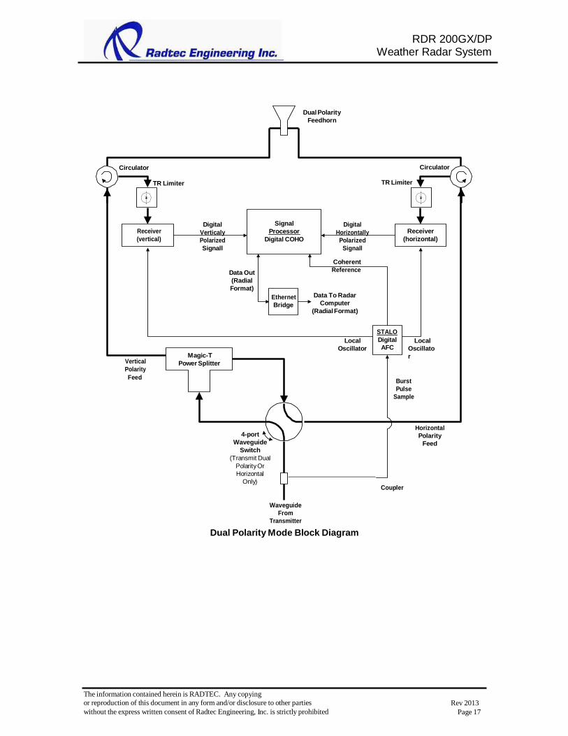
Page 17
RDR 200GX/DP Weather Radar System
Dual Polarity
Feedhorn
Circulator Circulator
TR Limiter TR Limiter
Receiver
(vertical)
Digital
Verticaly
Polarized
Signall
Signal
Processor
Digital COHO
Digital
Horizontally
Polarized
Signall
Receiver
(horizontal)
Data Out
(Radial
Format)
Ethernet
Bridge
Coherent
Reference
Data To Radar
Computer
(Radial Format)
Vertical
Polarity
Magic-T
Power Splitter
Local
Oscillator
STALO
Digital
AFC
Local
Oscillato
r
Feed Burst
Pulse
Sample
4-port
Waveguide
Switch
(Transmit Dual
Polarity Or
Horizontal
Only)
Coupler
Horizontal
Polarity
Feed
Waveguide
From
Transmitter
Dual Polarity Mode Block Diagram

The information contained herein is RADTEC. Any copying
or reproduction of this document in any form and/or disclosure to other parties
without the express written consent of Radtec Engineering, Inc. is strictly prohibited
Rev 2013
Page 18
RDR 200GX/DP Weather Radar System
Dual Polarity
Feedhorn
Circulator Circulator
TR Limiter TR Limiter
Receiver
(vertical)
Digital
Verticaly
Polarized
Signall
Signal
Processor
Digital COHO
Digital
Horizontally
Polarized
Signall
Receiver
(horizontal)
Data Out
(Radial
Format)
Coherent
Reference
Ethernet
Bridge
Vertical
Polarity
Magic-T
Power Splitter
Local
Oscillator
STALO
Digital
AFC
Local
Oscillator
Feed Burst
Pulse
Sample
4-port
Waveguide
Switch
(Transmit Dual
Polarity Or
Horizontal
Only)
Coupler
Horizontal
Polarity
Feed
Waveguide
From
Transmitter
Horizontal Only And LDR Mode Block Diagram
A power splitter is used to divide the transmitter’s output equally between the
horizontally and vertically polarized antenna feeds. A separate receiver is used for each
polarity. The major advantage of this method is that it is entirely electronic, and
therefore highly reliable.
A bypass arrangement is included to bypass the power splitter and provide full
transmitter output for operation in conventional single polarity, horizontally polarized
mode.

The information contained herein is RADTEC. Any copying
or reproduction of this document in any form and/or disclosure to other parties
without the express written consent of Radtec Engineering, Inc. is strictly prohibited
Rev 2013
Page 19
RDR 200GX/DP Weather Radar System
The received horizontal and vertical signals are converted to a common I/F frequency,
and are digitized and multiplexed onto a fiber optic link for transmission to the Enigma
III Signal Processor.
The signal processor processes the two data streams simultaneously in real time.
The output from the signal processor is a real-time data stream in radial format. Each
radial of data includes an ID (radar ID, azimuth and elevation angles, time, etc.) followed
by the data for each range bin in the radial. Each radial is a complete data set for that
radial.
Note that when operating in dual polarity mode, the output data rate is significantly
higher than in single polarity mode. In single polarity mode, the data includes reflectivity
(Z), velocity (V) and spectrum width (W) data values for each range bin. In dual polarity
mode, the data includes Z, V and W as well as data values for ZDR, KDP, LDR, DP and
HV. To preserve full real time operation, the data link between the radar and the central
site must have sufficient bandwidth to handle the additional products. In most cases, this
will require the full bandwidth of at least a T1/E1 (1.544/2.048 Mbits/sec) circuit.
As a reference, the AMS Bulletin, Vol. 80, No. 3, March 1999 includes a paper by Zrnic
and Ryzhkov titled Polarimetry for Weather Surveillance Radars that provides a
substantial amount of information about dual polarity applications.

RDR 200GX/DP Weather Radar System
The information contained herein is RADTEC. Any copying
or reproduction of this document in any form and/or disclosure to other parties
without the express written consent of Radtec Engineering, Inc. is strictly prohibited
Rev 2013
Page 20
RDR Radar Technical Characteristics
RDR Model RDR-200GX/DP
Summary Advanced technology, 200 kW X-Band Doppler weather radar with
precipitation measurement capability
Transmitter
Technology Coaxial Magnetron
Linear IGBT Solid State Modulator
Frequency X-band, tunable 9.3 to 9.7 GHz
Peak Power 200,000 Watts
Pulse Width Programmable 0.2 µsec to 4.5 µsec.
PRF Programmable, 500 to 5000 pulses per second
Polarization Programmable linear horizontal or
simultaneous horizontal & vertical dual polarity
Receiver
Technology Integrated low noise front end, digital I/F
Minimum
Detectable Signal
-114 dBm (2 µs pulse)
Dynamic Range 90 to >110 dB
Noise Figure 3 dB
dBz @ 50 km -23.59 dBZ (4.5 µsec. P/W, single polarity mode)
Signal Processor
Technology ENIGMA IV
Antenna
Size 8 ft (2.4 m) offset feed / 14 ft ( 4.3 m
Beam Width 0.9° for 8 ft (2.4 m) antenna / 0.5 for 4.3m
Gain 45 dB for 8 ft (2.4 m) antennas
Side Lobes Typically -35 dBc

RDR 200GX/DP Weather Radar System
The information contained herein is RADTEC. Any copying
or reproduction of this document in any form and/or disclosure to other parties
without the express written consent of Radtec Engineering, Inc. is strictly prohibited
Rev 2013
Page 21
RDR Model RDR-200GXDP
Pedestal
Technology Long life AC motors
Azimuth 360°, 0 - 4 rpm
Azimuth Accuracy ±0.1°
Elevation Range 360° continuous with offset feed antenna
Elevation Rate 0 - 15°/sec.
Elevation Accuracy ±0.1°
Radome
Size 12 ft (3.7 m) diameter / 22 ft (6.7 m )
Construction A-sandwich
Attenuation Loss 0.3 dB typical, A-sandwich radome
Wind Survival (for
undamaged
radome)
>138 mph (230 km/hr)
Specifications subject to change without notice as product improvements are made.
Sales and Program Management Office 2500 Woodruff Spur, Wayzata, MN 55391 USA Tel 1-952-473-3483 Email: [email protected]