Embed Size (px)
Citation preview

57
KOP-GRID®
TaperedGridCouplings
Interchangeablewith other TaperedGrid Couplings
Tapered,Shot peened gridsQuick, easy installationLow Maintenance
For:Petrochemicaland RefiningMaterial HandlingPulp and PaperFood and TextileGeneral Purpose
Index:Page
HOW TO ORDER .......................................... 61, 64
Technical Advantages ................................... 58, 59
Service Factors ................................................... 60
Interchange Chart ............................................... 61
Selection Procedure............................................ 61
T10 and T20 Standard Couplings ................. 62, 63
Engineering Data ................................................ 65
T31 Full Spacer Coupling ............................. 66, 67
T35 Half Spacer Coupling ............................. 68, 69

58
® KOP-GRID® Couplings
Technical Advantages
Torsional DampingThe grid design functions as a resilient coupling by damping torsionalvibration and cushioning shock loads, resulting in reduced vibration atthe output end of the coupling. Peak loading is reduced, for smoothtorque transmission, to help protect connected equipment from poten-tially damaging vibratory loads.
Light LoadThe outer edges of the grid contact the hubtapered teeth for light loads, leaving a longspan to bear the load variations and still com-pensate for misalignment.
Normal LoadThe grid is free to flex and dampen shockloads, even as the load increases. The spanbetween the support ends shortens with in-creasing load, however the grid is still free toflex, cushioning shock and compensating formisalignment.
Shock LoadThe KOP-GRID® coupling when under ex-treme loads, transmits the full load directlyto driven equipment with the entire grid infull contact with the hub tapered teeth. Yet,the coupling is flexible within its rated capac-ity.
Input: Shock loadingand vibration
Output: Dampened vibrationand shock absorption
KOP-GRID® tapered grid couplings are your best choice to protect your investment in expensive drivingand driven equipment from misalignment, shock loads and vibration, while accommodating reasonableshaft end float.
Offset (Parallel)Movement of the grid in the hub groovesaccommodates parallel misalignment whiledampening shock and vibration.
AngularWith angular misalignment, the grid/groovedesign permits a rocking and sliding actionof grid and hubs without loss of powerthrough the resilient grid.
End Float (Axial)End float is permitted for both driving anddriven shafts because the grid slides freelyin the lubricated grooves.
↓↓↓↓↓ ↓↓↓↓↓ ↓↓↓↓↓ ←←←←← →→→→→
Overload ProtectionA second function of the grid design is that it can act much like a protec-tive overload shear device. During an extreme overload, the grid canshear, reducing the possibility of damage to expensive machinery andequipment.

59
®
T10 with Horizontal Split CoversIdeal for multipurpose industrial applications� Typical Applications:
- Pulp Processing Machinery- Agitators and Aerators- Wood Grinders, Chippers- Conveyors and Crushers- Steel and Aluminum shaping- Textile and Food Machinery
� Interchangeable with other tapered grid couplings� Horizontally split, aluminum alloy cover� Easy installation and access to tapered grids� Easy assembly in confined spaces� Absorbs moderate shock and vibratory loads. Torsionally flexible� Suitable for reversing service� Socket head capscrews and self-locking nuts� Steel hubs — straight bores or standard bushings
T35 Half SpacerFor applications requiring moderate shaft separations� Typical Applications:
- Fans, Blowers and Dryers- Centrifugal Process Pumps- Vacuum Pumps- Crushers and Pulverizers
� Interchangeable with other tapered grid couplings� Half spacer style for shorter shaft separations� Uses standard, interchangeable
components� Horizontally split, aluminum alloy cover� Steel hubs — straight bores or standard bushings� Easily installed and maintained
T20 with Vertical Split Covers Designed for higher speed applications� Typical Applications:
- Food and Grain Process Equipment- Chemical Process Machinery- Screw Compressors and Vacuum Pumps- Fans, Blowers and Dryers- Gearbox Input Shafts
� Interchangeable with other tapered grid couplings� Vertically split, corrosion resistant steel covers. Grade 8 hex head
fasteners� Torsionally flexible� Steel hubs — straight bores or standard bushings
T31 Full SpacerFor general purpose, process pumpapplications� Typical Applications:
- Centrifugal Pumps such as: Stock and Chemical Process- Fish and Slurry Pumps- Petrochemical Process Lines- Municipal and Wastewater Pumps- Descaling and Pulp Pumps
� Interchangeable with other tapered grid couplings� Full spacer version for process pumps� Drop-out center spacer section for easy pump & equipment
maintenance� Horizontally split, aluminum alloy cover� Standard shaft separations available from stock. Large bore
capacity shaft hubs� Grade 8 hex head shaft/spacer hub fasteners
T31 T35
T20T10
KOP-GRID® Couplings
60
®
TypicalApplication Service
FactorAGITATORS
Pure Liquids .......................................................... 1.0Liquids & Solids .................................................... 1.25Liquids — Variable Density ................................... 1.25
BLOWERSCentrifugal ............................................................. 1.0Lobe ...................................................................... 1.5Vane ...................................................................... 1.25
BRIQUETTE MACHINES ........................................... 2.0CAR PULLERS — Intermittent Duty .......................... 1.5COMPRESSORS
Centrifugal ............................................................. 1.0Centriaxial ............................................................. 1.25Lobe ...................................................................... 1.5Reciprocating — Multi-Cylinder ............................ 2.0
CONVEYORS — LIGHT DUTY UNIFORMLY FEDApron, Bucket, Chain, Flight, Screw ..................... 1.25Assembly, Belt ....................................................... 1.0Oven ...................................................................... 1.5
CONVEYORS — HEAVY DUTY NOT UNIFORMLY FEDApron, Bucket, Chain, Flight, Oven ....................... 1.5Assembly, Belt ....................................................... 1.25Reciprocating, Shaker ........................................... 2.5
CRANES AND HOISTS (NOTE 1 and 2)Main hoists, Reversing .......................................... 2.5Skip Hoists, Trolley & Bridge Drives ...................... 2.0Slope ..................................................................... 2.0
CRUSHERSOre, Stone ............................................................. 3.0
DREDGESCable Reels ........................................................... 1.75Conveyors ............................................................. 1.5Cutter Head Jig Drives .......................................... 2.5Maneuvering Winches ........................................... 1.75Pumps ................................................................... 1.75Screen Drives ........................................................ 1.75Stackers ................................................................ 1.75Utility Winches ....................................................... 1.5
ELEVATORS (NOTE 2)Bucket ................................................................... 1.75Centrifugal & Gravity Discharge ........................... 1.5Escalators ............................................................. 1.5Freight ................................................................... 2.5
FANSCentrifugal ............................................................. 1.0Cooling Towers ...................................................... 1.5Forced Draft .......................................................... 1.5Induced Draft without Damper Control ............................................................... 2.0
FEEDERSApron, Belt, Disc, Screw ....................................... 1.25Reciprocating ........................................................ 2.5
TypicalApplication Service
FactorGENERATORS —
(Not Welding) ........................................................... 1.0HAMMER MILLS ........................................................ 2.0LAUNDRY WASHERS —
Reversing ............................................................. 2.0LAUNDRY TUMBLERS .............................................. 2.0LINE SHAFT .............................................................. 1.5LUMBER INDUSTRY
Barkers — Drum Type .............................................. 2.0Edger Feed .............................................................. 2.0Live Rolls ................................................................. 2.0Log Haul — Incline .................................................. 2.0Log Haul — Well type .............................................. 2.0Off Bearing Rolls ...................................................... 2.0Planer Feed Chains ................................................. 1.75Planer Floor Chains ................................................. 1.75Planer Tilting Hoist ................................................... 1.75Slab Conveyor .......................................................... 1.5Sorting Table ............................................................ 1.5Trimmer Feed ........................................................... 1.75
MARINE PROPULSIONMain Drives .............................................................. 2.0
MACHINE TOOLSBending Roll ............................................................ 2.0Plate Planer ............................................................. 1.5Punch Press — Gear Driven ................................... 2.0Tapping Machines .................................................... 2.5Other Machine Tools Main Drives .......................................................... 1.5 Auxiliary Drives .................................................... 1.25
METAL MILLSDraw Bench — Carriage .......................................... 2.0Draw Bench — Main Drive ...................................... 2.0Forming Machines ................................................... 2.0Slitters ...................................................................... 1.5Table Conveyors Non-Reversing ..................................................... 2.25 Reversing ............................................................. 2.5Wire Drawing & Flattening Machine ........................ 2.0Wire Winding Machine ............................................. 1.75
METAL ROLLING MILLS (NOTE 1)Blooming Mills .......................................................... *Coilers, hot mill ........................................................ 2.0Coilers, cold mill ....................................................... 1.25Cold Mills ................................................................. 2.0Cooling Beds ........................................................... 1.75Door Openers .......................................................... 2.0Draw Benches .......................................................... 2.0Edger Drives ............................................................ 1.75Feed Rolls, Reversing Mills ..................................... 3.5Furnace Pushers ..................................................... 2.5Hot Mills ................................................................... 3.0Ingot Cars ................................................................ 2.5Kick-outs .................................................................. 2.5Manipulators ............................................................ 3.0Merchant Mills .......................................................... 3.0Piercers .................................................................... 3.0Pusher Rams ........................................................... 2.5Reel Drives .............................................................. 1.75Reel Drums .............................................................. 2.0Reelers ..................................................................... 3.0Rod and Bar Mills .................................................... 1.5Roughing Mill Delivery Table ................................... 3.0Runout Tables Reversing ............................................................. 3.0 Non-Reversing ..................................................... 2.0Saws, hot & cold ...................................................... 2.5Screwdown Drives ................................................... 3.0Skelp Mills ................................................................ 3.0Slitters ...................................................................... 3.0Slabbing Mills ........................................................... 3.0Soaking Pit Cover Drives ......................................... 3.0Straighteners ............................................................ 2.5Tables, transfer & runout .......................................... 2.0Thrust Block ............................................................. 3.0Traction Drive ........................................................... 3.0Tube Conveyor Rolls ................................................ 2.5Unscramblers ........................................................... 2.5Wire Drawing ........................................................... 1.5
MILLS, ROTARY TYPEBall ........................................................................... 2.25Dryers & Coolers ..................................................... 2.0Hammer ................................................................... 1.75Kilns ......................................................................... 2.0
TypicalApplication Service
FactorPebble & Rod ........................................................... 2.0Pug ........................................................................... 1.75Tumbling Barrels ...................................................... 2.0
MIXERSConcrete Mixers ....................................................... 1.75Drum Type ................................................................ 1.5
OIL INDUSTRYChillers ..................................................................... 1.25Paraffin Filter Press ................................................. 1.75
PAPER MILLSBarker Auxiliaries, Hydraulic .................................... 2.0Barker, Mechanical .................................................. 2.0Barking Drum Spur Gear Only ................................ 2.25Beater & Pulper ....................................................... 1.75Bleacher ................................................................... 1.0Calenders ................................................................. 2.0Chippers ................................................................... 2.5Coaters .................................................................... 1.0Converting Machines, except Cutters, Platers .......................................... 1.5Couch Roll ............................................................... 1.75Cutters, Platers ........................................................ 2.0Cylinders .................................................................. 1.75Disc Refiners ............................................................ 1.75Dryers ...................................................................... 1.75Felt Stretcher ........................................................... 1.25Felt Whipper ............................................................. 2.0Jordans .................................................................... 1.75Line Shaft ................................................................. 1.5Log Haul ................................................................... 2.0Pulp Grinder ............................................................. 1.75Press Roll ................................................................. 2.0Reel .......................................................................... 1.5Stock Chests ............................................................ 1.5Suction Roll .............................................................. 1.75Washers & Thickeners ............................................. 1.5Winders .................................................................... 1.5
PRINTING PRESSES ................................................ 1.5PULLERS — Barge Haul ........................................... 2.0PUMPS
Centrifugal ............................................................... 1.0Boiler Feed ............................................................... 1.5Reciprocating Single Acting 1 or 2 Cylinders ................................................... 2.25 3 or more Cylinders ............................................ 1.75Double Acting ........................................................... 2.0Rotary, Gear, Lobe, Vane ......................................... 1.5
RUBBER INDUSTRYMixer — Banbury ..................................................... 2.5Rubber Calendar ..................................................... 2.0Rubber Mill (2 or more) ............................................ 2.25Sheeter .................................................................... 2.0Tire Building Machines ............................................ 2.5Tire & Tube Press Openers ..................................... 1.0Tubers & Strainers ................................................... 2.0
SCREENSAir Washing .............................................................. 1.0Grizzly ...................................................................... 2.0Rotary — Stone or Gravel ....................................... 1.5Traveling Water Intake .............................................. 1.25Vibrating ................................................................... 2.5
SEWAGE DISPOSAL EQUIPMENTBar Screens ............................................................. 1.25Chemical Feeders .................................................... 1.25Collectors, Circuline or Straightline ......................... 1.25Dewatering Screens ................................................ 1.25Grit Collectors .......................................................... 1.25Scum Breakers ........................................................ 1.25Slow or Rapid Mixers ............................................... 1.25Sludge Collectors ..................................................... 1.25Thickeners ............................................................... 1.25Vacuum Filters ......................................................... 1.25
STEERING GEAR ...................................................... 1.0STOKERS .................................................................. 1.0WINCH ........................................................................ 1.5WINDLASS ................................................................ 1.75
* Refer to KOP-FLEX
NOTES(1) Maximum Torque at the coupling must not exceed
Rated Torque of the coupling.(2) Check local and industrial safety codes.
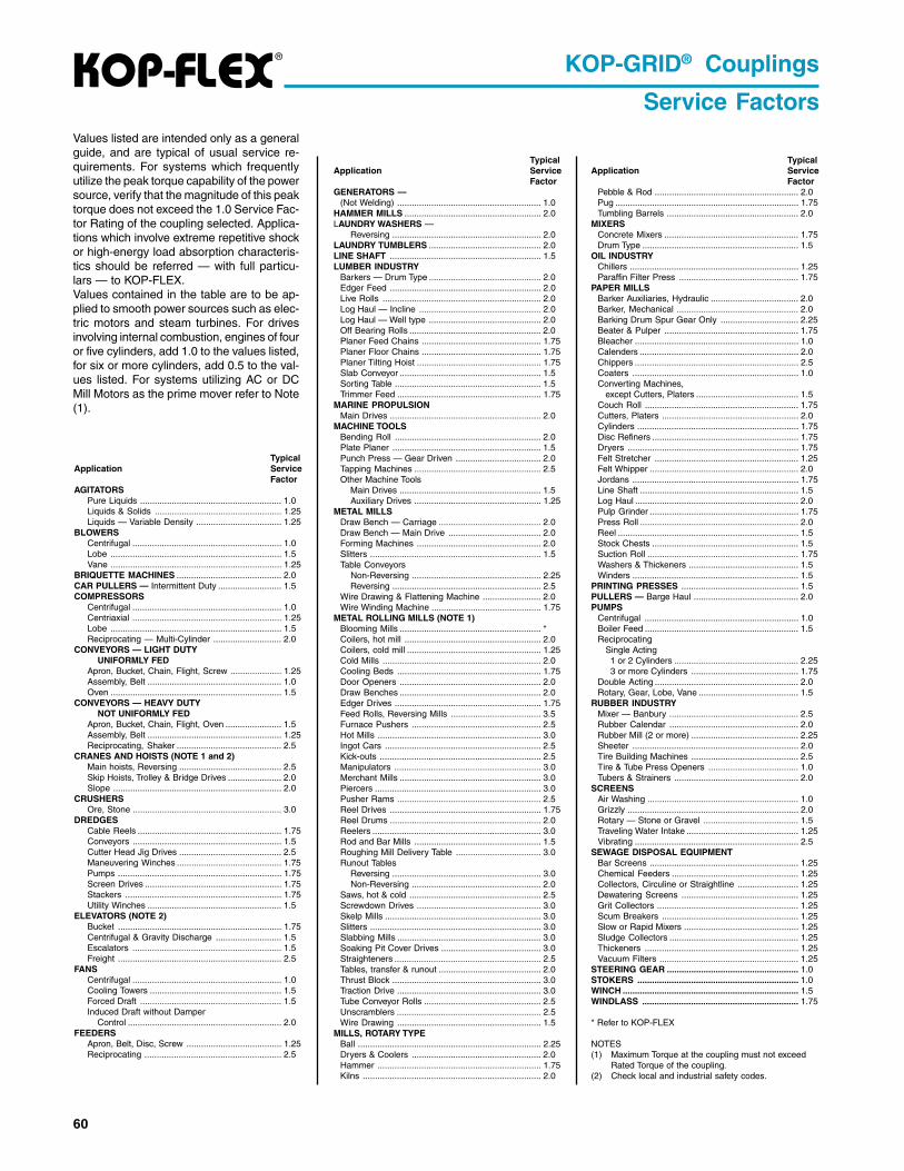
Values listed are intended only as a generalguide, and are typical of usual service re-quirements. For systems which frequentlyutilize the peak torque capability of the powersource, verify that the magnitude of this peaktorque does not exceed the 1.0 Service Fac-tor Rating of the coupling selected. Applica-tions which involve extreme repetitive shockor high-energy load absorption characteris-tics should be referred — with full particu-lars — to KOP-FLEX.Values contained in the table are to be ap-plied to smooth power sources such as elec-tric motors and steam turbines. For drivesinvolving internal combustion, engines of fouror five cylinders, add 1.0 to the values listed,for six or more cylinders, add 0.5 to the val-ues listed. For systems utilizing AC or DCMill Motors as the prime mover refer to Note(1).
KOP-GRID® Couplings
Service Factors

61
®
Kop-Grid Coupling Interchange GuideKop-Grid couplings are interchangeable with other tapered grid couplings,component by component • hubs, grids, seals, and cover assembly
1. Coupling Type:Select the appropriate KOP-GRID coupling type for your application.See page 3 for coupling types.
2. Coupling Size:Step 1: Determine the proper service factor from page M-60.
Step 2: Calculate the required HP/100 RPM, using the HP rating ofthe drive and the coupling speed (RPM) as shown below:
HP x SERVICE FACTOR x 100= HP/100 RPMRPM
Step 3: Select the coupling size having a rating sufficient to handlethe required HP/100 RPM at the appropriate service factor.
KOP-GRID® Couplings
Selection ProcedureStep 4: Verify that the actual coupling speed (RPM) is equal to orless than the maximum allowable speed rating of the coupling.
Step 5: Verify that the maximum bore of the coupling selected isequal to or larger than either of the equipment shafts.
Step 6: Check the overall dimensions to ensure coupling will notinterfere with the coupling guard, piping, or the equipment housingsand that it will fit the required shaft separation.
Description
HUB = Rough Bore HubHUBxBORE = Finished Bore HubHUBx(Bushing Size) = Hubs for Split Taper BushingGRID = Tapered GridT10 CGA = Cover and Grid Ass’y HorizontalT20 CGA = Cover and Grid Ass’y VerticalT10 Cover = Horizontal Split CoverT20 Cover = Vertical Split CoverT10 AK = Horizontal Cover Accessory KitT20 AK = Vertical Cover Accessory KitSHUB = Shaft HubSHUBx(Bushing Size) = Shaft Hub for Split Taper BushingSPHxxx = Distance Between Shaft Ends (x.xx)
PART NUMBER EXPLANATIONComplete Rough Bore Coupling
1000 Series
Size (020 to 140)
T10 = Horizontal Split CoverT20 = Vertical Split CoverT31 = Full SpacerT35 = Half Spacer
1 020 T10
Coupling Parts
ex. 1020 HUBx5/8
* Manufacturers of comparable tapered grid couplings.
DIRG-POK * KLAF * EGDOD * YOJEVOL
T0201 T0201 T0201 0202T0301 T0301 T0301 0302T0401 T0401 T0401 0402T0501 T0501 T0501 0502T0601 T0601 T0601 0602
T0701 T0701 T0701 0702T0801 T0801 T0801 0802T0901 T0901 T0901 0902T0011 T0011 T0011 0012T0111 T0111 T0111 0112
T0211 T0211 T0211 0212T0311 T0311 T0311 0312T0411 T0411 T0411 0412
sepyTgnilpuoC DIRG-POK * KLAF * EGDOD * YOJEVOL
revoCtilpSyllatnoziroH 01T 01T 01T HrevoCtilpSyllacitreV 02T 02T 02T VgnilpuoC)lluF(recapS 13T 13T 13T A/N
gnilpuoCrecapSflaH 53T 53T 53T A/N

62
®
T20 WITH VERTICAL SPLIT COVERS
T10 WITH HORIZONTAL SPLIT COVERS
T10 & T20 WITH BROWNING® SPLIT TAPER BUSHING
KOP-GRID® Couplings
T10 W/BUSHINGS T20 W/BUSHINGS

63
®
Table No. 2 Specifications — KOP-GRID T20 with Vertical Split Covers
Table No. 1 Specifications — KOP-GRID T10 with Horizontal Split Covers
Table No. 3 Specifications — KOP-GRID T10 & T20 Couplings for BROWNING® Split Taper Bushings
KOP-GRID® Couplings
Note: See Table 1 and 2 for maximum speeds.
gnilpuoCeziS
PHrep001MPR
euqroTgnitaR).ni-.bl(
mumixaMdeepS
MPR
mumixaMeroB
erauqS()yeK
.tW.glpCoNhtiW
.bl-eroB
sehcnI-snoisnemiD
A B C D E S paG
0201 86.0 224 0054 521.1 2.4 00.4 88.3 88.1 65.1 26.2 63.1 521.0301 39.1 0021 0054 573.1 7.5 83.4 88.3 88.1 49.1 96.2 45.1 521.0401 22.3 0002 0054 526.1 5.7 26.4 21.4 00.2 52.2 57.2 85.1 521.0501 36.5 0053 0054 578.1 21 44.5 88.4 83.2 26.2 21.3 57.1 521.0601 58.8 0055 0534 521.2 61 49.5 21.5 05.2 00.3 26.3 60.2 521.
0701 31 0008 5214 005.2 22 83.6 21.6 00.3 44.3 57.3 21.2 521.0801 72 00561 0063 000.3 04 46.7 21.7 05.3 21.4 75.4 45.2 521.0901 84 00003 0063 005.3 55 83.8 88.7 88.3 88.4 18.4 18.2 521.0011 18 00505 0442 000.4 39 48.9 96.9 57.4 95.5 21.6 - 881.0111 121 00057 0522 005.4 911 26.01 91.01 00.5 13.6 63.6 - 881.
0211 771 000011 5202 000.5 971 21.21 00.21 88.5 60.7 45.7 - 052.0311 752 000061 0081 000.6 762 26.31 00.31 83.6 65.8 96.7 - 052.0411 073 000032 0561 052.7 393 21.51 56.41 91.7 00.01 19.7 - 052.
gnilpuoCeziS
PHrep001MPR
euqroTgnitaR).ni-.bl(
mumixaMdeepS
MPR
mumixaMeroB
erauqS()yeK
.tW.glpCoNhtiW
.bl-eroB
sehcnI-snoisnemiD
A B C D E S paG
0201 86.0 224 0006 521.1 3.4 83.4 88.3 88.1 65.1 59.0 63.1 521.0301 39.1 0021 0006 573.1 7.5 57.4 88.3 88.1 49.1 89.0 45.1 521.0401 22.3 0002 0006 526.1 4.7 60.5 21.4 00.2 52.2 00.1 85.1 521.0501 36.5 0053 0006 578.1 21 18.5 88.4 83.2 26.2 22.1 57.1 521.0601 58.8 0055 0006 521.2 61 83.6 21.5 05.2 00.3 82.1 60.2 521.
0701 31 0008 0055 005.2 32 18.6 21.6 00.3 44.3 33.1 21.2 521.0801 72 00561 0574 000.3 93 88.7 21.7 05.3 21.4 57.1 45.2 521.0901 84 00003 0004 005.3 65 21.9 88.7 88.3 88.4 88.1 18.2 521.0011 18 00505 0523 000.4 39 05.01 96.9 57.4 95.5 63.2 - 881.0111 121 00057 0003 005.4 021 52.11 91.01 00.5 13.6 35.2 - 881.
0211 771 000011 0072 000.5 081 65.21 00.21 88.5 60.7 88.2 - 052.0311 752 000061 0042 000.6 072 88.41 00.31 83.6 65.8 69.2 - 052.0411 073 000032 0022 052.7 793 83.61 56.41 91.7 00.01 80.3 - 052.
gnilpuoCeziS
.P.Hrep001MPR
euqroTgnitaR).ni-.bl(
gnihsuBeroBegnaR
.tWsseL
gnihsuB).bl(
sehcnI-snoisnemiD
paGA
B C D
E
H01TrevoC
02TrevoC
01TrevoC
02TrevoC
0401 89.1 0521 G 0.1-573. 3.6 26.4 60.5 83.4 49.1 00.2 57.2 00.1 00.1 521.0501 91.4 0462 H 5.1-573. 0.01 44.5 18.5 88.4 91.2 05.2 21.3 52.1 52.1 521.0601 17.8 0055 1P 57.1-5. 3.31 49.5 83.6 88.5 36.2 00.3 26.3 52.1 49.1 521.0701 31 0008 1P 57.1-5. 7.81 83.6 68.6 88.5 36.2 00.3 57.3 83.1 49.1 521.0801 62 00561 1Q 886.2-57. 6.03 46.7 88.7 91.7 52.3 31.4 65.4 57.1 05.2 521.
0901 33 00502 1Q 886.2-57. 6.44 83.8 21.9 44.7 83.3 31.4 18.4 88.1 05.2 521.0011 56 00904 1R 57.3-521.1 07 88.9 05.01 00.9 21.4 83.5 21.6 83.2 88.2 881.0111 56 00904 1R 57.3-521.1 49 26.01 52.11 52.9 52.4 83.5 63.6 05.2 88.2 881.0211 721 00897 1S 52.4-886.1 041 21.21 65.21 31.11 60.5 83.6 55.7 00.3 83.4 052.0311 452 000061 0U 05.5-52.3 991 26.31 88.41 65.11 91.5 83.8 96.7 00.3 49.4 052.0411 792 000781 0U 05.5-52.3 492 21.51 83.61 91.11 13.5 83.8 29.7 21.3 49.4 052.

64
® KOP-GRID® Couplings
Table No. 4 Kop-Grid Couplings — Hubs, Grid, Cover, Seal and Fastener Kits
HOW TO ORDER T10 & T20 COUPLINGS
� To order complete Rough Bore Couplings, specify by Part Number only, for example “1020T10”; Rough Bore Hubs, and T10 Cover and GridAssembly is included.
� To order a Coupling with Finished Bore or Bored to Size Hubs, order two hubs, one Cover and Grid Assembly. Specify Hub Part Number x BoreSize, for example “1020HUBx5/8”. If the bore size indicated is shown in Table No. 4, above, then the hub is a Standard Finished Bore Hub;otherwise a Rough Bore Hub must be rebored.
� To order a Coupling with Split Taper Bushings, order two Bushed Hubs and two appropriate Bushings, one Cover and Grid Assembly.� Cover Kits include Seal and Fastener Sets. The Assembly Kits shown are for REPLACEMENT ONLY.
Table No. 5 Standard Clearance Bored Hubs with Set-Screws
*Complete Hub Part Number by adding Bore Size. Other bores are available by boring Rough Bore Hubs.NOTE – Hub Numbers 1020 HUB through 1190 HUB have clearance fit bores with setscrew over Keyway.
– Hub Numbers 1100 HUB through 1140 HUB have interference fit bores with no Setscrew.
KOP-FLEX Coupling GreasesKOP-FLEX offers greases specifically designed for use in coupling applications. To en-sure proper lubrication and long service life, use KOP-FLEX KSG Standard CouplingGrease. See page 27 for detailed specifications.
.glpCeziS
hguoRetelpmoC �
sgnilpuoCeroB sbuH latnoziroH01T lacitreV02T
01TlatnoziroH
tilpSrevoC
02TlacitreV
tilpSrevoC
dirGbuH
eroBoN
dehsiniFeroB
dna �
otderoBeziS
dirGbuH
dehsuB
-hsuBgni
derepaTdirGtiK
revoCdnadirG
ylbmessA
revoCtiK
yrosseccAtiK
revoCdnadirG
ylbmessA
revoCtiK
yrosseccAtiK
0201 01T0201 02T0201 BUH0201 eroBxBUH0201 — — DIRG0201 AGC01T0201 REVOC01T0201 KA01T0201 AGC02T0201 REVOC02T0201 KA02T0201
0301 01T0301 02T0301 BUH0301 eroBxBUH0301 — — DIRG0301 AGC01T0301 REVOC01T0301 KA01T0301 AGC02T0301 REVOC02T0301 KA02T0301
0401 01T0401 02T0401 BUH0401 eroBxBUH0401 GXBUH0401 G DIRG0401 AGC01T0401 REVOC01T0401 KA01T0401 AGC02T0401 REVOC02T0401 KA02T0401
0501 01T0501 02T0501 BUH0501 eroBxBUH0501 HXBUH0501 H DIRG0501 AGC01T0501 REVOC01T0501 KA01T0501 AGC02T0501 REVOC02T0501 KA02T0501
0601 01T0601 02T0601 BUH0601 eroBxBUH0601 PXBUH0601 1P DIRG0601 AGC01T0601 REVOC01T0601 KA01T0601 AGC02T0601 REVOC02T0601 KA02T0601
0701 01T0701 02T0701 BUH0701 eroBxBUH0701 PXBUH0701 1P DIRG0701 AGC01T0701 REVOC01T0701 KA01T0701 AGC02T0701 REVOC02T0701 KA02T0701
0801 01T0801 02T0801 BUH0801 eroBxBUH0801 QXBUH0801 1Q DIRG0801 AGC01T0801 REVOC01T0801 KA01T0801 AGC02T0801 REVOC02T0801 KA02T0801
0901 01T0901 02T0901 BUH0901 eroBxBUH0901 QXBUH0901 1Q DIRG0901 AGC01T0901 REVOC01T0901 KA01T0901 AGC02T0901 REVOC02T0901 KA02T0901
0011 01T0011 02T0011 BUH0011 eroBxBUH0011 RXBUH0011 1R DIRG0011 AGC01T0011 REVOC01T0011 KA01T0011 AGC02T0011 REVOC02T0011 KA02T0011
0111 01T0111 02T0111 BUH0111 eroBxBUH0111 RXBUH0111 1R DIRG0111 AGC01T0111 REVOC01T0111 KA01T0111 AGC02T0111 REVOC02T0111 KA02T0111
0211 01T0211 02T0211 BUH0211 eroBxBUH0211 SXBUH0211 1S DIRG0211 AGC01T0211 REVOC01T0211 KA01T0211 AGC02T0211 REVOC02T0211 KA02T0211
0311 01T0311 02T0311 BUH0311 eroBxBUH0311 UXBUH0311 0U DIRG0311 AGC01T0311 REVOC01T0311 KA01T0311 AGC02T0311 REVOC02T0311 KA02T0311
0411 01T0411 02T0411 BUH0411 eroBxBUH0411 UXBUH0411 0U DIRG0411 AGC01T0411 REVOC01T0411 KA01T0411 AGC02T0411 REVOC02T0411 KA02T0411
buH*.oNtraP
)sehcnI(seroBdradnatS
2/1 8/5 4/3 8/7 1 8/11 4/11 8/31 2/11 8/51 4/31 8/71 2 8/12 4/12 8/32 2/12 8/52 4/32 8/72 3 8/33H0201 X X X X X XH0301 X X X X X X XH0401 X X X X X X XH0501 X X X X X X XH0601 X X X X X X X
H0701 X X X X X X X X
H0801 X X X X X X XH0901 X X
65
®
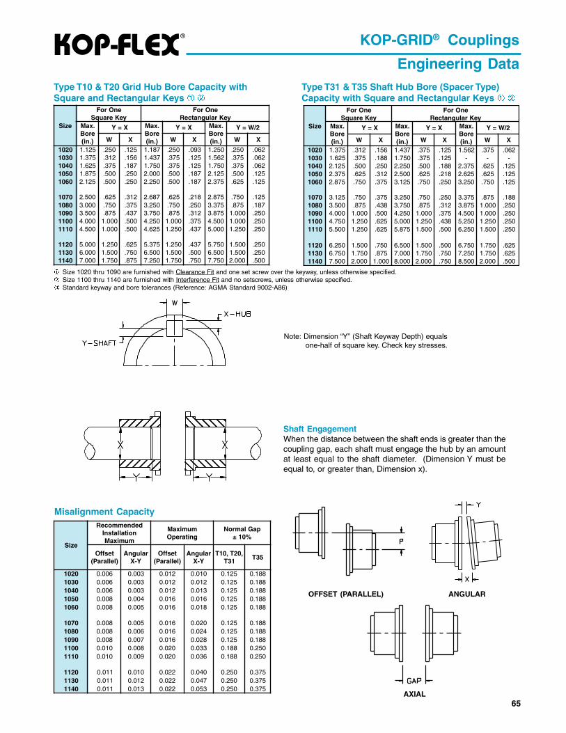
Type T31 & T35 Shaft Hub Bore (Spacer Type)Capacity with Square and Rectangular Keys À Á
À Size 1020 thru 1090 are furnished with Clearance Fit and one set screw over the keyway, unless otherwise specified.Á Size 1100 thru 1140 are furnished with Interference Fit and no setscrews, unless otherwise specified. Standard keyway and bore tolerances (Reference: AGMA Standard 9002-A86)
Type T10 & T20 Grid Hub Bore Capacity withSquare and Rectangular Keys À Á
Misalignment Capacity
Shaft EngagementWhen the distance between the shaft ends is greater than thecoupling gap, each shaft must engage the hub by an amountat least equal to the shaft diameter. (Dimension Y must beequal to, or greater than, Dimension x).
OFFSET (PARALLEL) ANGULAR
AXIAL
Note: Dimension “Y” (Shaft Keyway Depth) equalsone-half of square key. Check key stresses.
KOP-GRID® Couplings
Engineering Data
eziS
enOroFyeKerauqS
enOroFyeKralugnatceR
.xaMeroB).ni(
X=Y .xaMeroB).ni(
X=Y .xaMeroB).ni(
2/W=Y
W X W X W X
0201 521.1 052. 521. 781.1 052. 390. 052.1 052. 260.0301 573.1 213. 651. 734.1 573. 521. 265.1 573. 260.0401 526.1 573. 781. 057.1 573. 521. 057.1 573. 260.0501 578.1 005. 052. 000.2 005. 781. 521.2 005. 521.0601 521.2 005. 052. 052.2 005. 781. 573.2 526. 521.
0701 005.2 526. 213. 786.2 526. 812. 578.2 057. 521.0801 000.3 057. 573. 052.3 057. 052. 573.3 578. 781.0901 005.3 578. 734. 057.3 578. 213. 578.3 000.1 052.0011 000.4 000.1 005. 052.4 000.1 573. 005.4 000.1 052.0111 005.4 000.1 005. 526.4 052.1 734. 000.5 052.1 052.
0211 000.5 052.1 526. 573.5 052.1 734. 057.5 005.1 052.0311 000.6 005.1 057. 005.6 005.1 005. 005.6 005.1 052.0411 000.7 057.1 578. 052.7 057.1 057. 057.7 000.2 005.
eziS
enOroFyeKerauqS
enOroFyeKralugnatceR
.xaMeroB).ni(
X=Y .xaMeroB).ni(
X=Y .xaMeroB).ni(
2/W=Y
W X W X W X
0201 573.1 213. 651. 734.1 573. 521. 265.1 573. 260.0301 526.1 573. 881. 057.1 573. 521. - - -0401 521.2 005. 052. 052.2 005. 881. 573.2 526. 521.0501 573.2 526. 213. 005.2 526. 812. 526.2 526. 521.0601 578.2 057. 573. 521.3 057. 052. 052.3 057. 521.
0701 521.3 057. 573. 052.3 057. 052. 573.3 578. 881.0801 005.3 578. 834. 057.3 578. 213. 578.3 000.1 052.0901 000.4 000.1 005. 052.4 000.1 573. 005.4 000.1 052.0011 057.4 052.1 526. 000.5 052.1 834. 052.5 052.1 052.0111 005.5 052.1 526. 578.5 005.1 005. 052.6 005.1 052.
0211 052.6 005.1 057. 005.6 005.1 005. 057.6 057.1 526.0311 057.6 057.1 578. 000.7 057.1 057. 052.7 057.1 526.0411 005.7 000.2 000.1 000.8 000.2 057. 005.8 000.2 005.
eziS
dednemmoceRnoitallatsnI
mumixaM
mumixaMgnitarepO
paGlamroN%01±
tesffO)lellaraP(
ralugnAY-X
tesffO)lellaraP(
ralugnAY-X
,02T,01T13T
53T
0201 600.0 300.0 210.0 010.0 521.0 881.00301 600.0 300.0 210.0 210.0 521.0 881.00401 600.0 300.0 210.0 310.0 521.0 881.00501 800.0 400.0 610.0 610.0 521.0 881.00601 800.0 500.0 610.0 810.0 521.0 881.0
0701 800.0 500.0 610.0 020.0 521.0 881.00801 800.0 600.0 610.0 420.0 521.0 881.00901 800.0 700.0 610.0 820.0 521.0 881.00011 010.0 800.0 020.0 330.0 881.0 052.00111 010.0 900.0 020.0 630.0 881.0 052.0
0211 110.0 010.0 220.0 040.0 052.0 573.00311 110.0 210.0 220.0 740.0 052.0 573.00411 110.0 310.0 220.0 350.0 052.0 573.0

66
® KOP-GRID® Couplings
T31 Full Spacer
KOP-GRID T31 Full Spacer Coupling Specifications
Specifications and selection data are subject to change without notice. Bushings not included.
� Weight is calculated with No Bore and minimum “BE” dimension.� See page 65 for standard “BE” dimensions and part numbers.
The KOP-GRID T31 full spacer coupling is designed for medium duty applications requiring greater shaft separations, such as process pumpsthat are typical of the Pulp & Paper, Petrochemical and Process industries. This full-flex spacer coupling is available in a wide variety of shaftseparations by using combinations of standard, interchangeable spacer hubs. The drop-out center section permits easy pump and equipmentmaintenance. The shaft hubs, normally furnished for a clearance fit to AGMA Standards, accept large equipment shafts for application versatility.The KOP-GRID T31 coupling is specifically engineered to be interchangeable with other tapered grid spacer couplings, by component— hubs (shaft and spacer), grid, seals — and cover assembly.
KOP-GRID T31 CouplingPart Numbers (see next page for spacer hubs)
A KOP-GRID T31 Full Spacer consists of the following components:Shaft Hubs - Two (2) shaft hubs with either a minimum bore or bored toaccept a BROWNING Split Taper bushing. Minimum bore hubs can besupplied bored-to-size at a nominal additional charge. Bushings are avail-able at an additional cost in a variety of bore sizes.Spacer Hubs - Two (2) Spacer Grid hubs are required. See Table onPage 65.T10 Cover and Grid Assembly - One (1) is required.
TYPE 31(FULL SPACER)
eziS
gnilpuoCgnitaR001/PH
MPR
euqroTgnitaR).ni-.bl(
mumixaMdeepS
MPR
mumixaMeroB .tW.glpC
oNhtiW-eroB
.bl �
)sehcnI(snoisnemiD egnalFsrenetsaF
A B
"EB" �
N F E U paGtfahSbuH
tfahSbuH
)dehsuB(niM xaM
reP.oNegnalFedarG&
aiD
0201 86.0 224 0063 573.1 000.1 5.8 00.4 83.1 05.3 00.8 40.2 83.3 30. 80. 881. 8rG4 052.0301 39.1 0021 0063 526.1 000.1 21 83.4 26.1 05.3 05.8 13.2 96.3 30. 80. 881. 8rG8 052.0401 22.3 0002 0063 521.2 057.1 91 26.4 21.2 05.3 05.8 60.3 44.4 30. 80. 881. 8rG8 052.0501 36.5 0053 0063 573.2 057.1 82 44.5 63.2 83.4 05.8 44.3 69.4 30. 80. 881. 8rG8 213.0601 58.8 0055 0063 578.2 834.2 34 49.5 88.2 00.5 00.31 60.4 17.5 60. 11. 881. 8rG8 573.
0701 31 0008 0063 521.3 886.2 45 83.6 21.3 00.5 00.31 82.4 20.6 60. 11. 881. 8rG21 573.0801 72 00561 0063 005.3 886.2 78 46.7 05.3 52.7 00.61 18.4 00.7 60. 11. 881. 8rG21 005.0901 84 00003 0063 000.4 057.3 331 83.8 20.4 52.7 00.61 95.5 96.8 60. 11. 881. 8rG21 526.0011 18 00505 0442 057.4 052.4 812 48.9 45.3 00.8 00.61 37.6 88.9 60. 21. 052. 8rG21 057.
eziS
SBUHdnarevoC01TylbmessAdirG
dirGderepaTtiK
01TtiKrevoC
01TyrosseccA
tiKtfahS
buHeroBoN
tfahSbuH
dehsuBgnihsuB
0201 BUHS0201 GXBUHS0201 G AGC01T0201 DIRG0201 REVOC01T0201 KA01T02010301 BUHS0301 GXBUHS0301 G AGC01T0301 DIRG0301 REVOC01T0301 KA01T03010401 BUHS0401 PXBUHS0401 1P AGC01T0401 DIRG0401 REVOC01T0401 KA01T04010501 BUHS0501 PXBUHS0501 1P AGC01T0501 DIRG0501 REVOC01T0501 KA01T05010601 BUHS0601 BXBUHS0601 B AGC01T0601 DIRG0601 REVOC01T0601 KA01T0601
0701 BUHS0701 QXBUHS0701 1Q AGC01T0701 DIRG0701 REVOC01T0701 KA01T07010801 BUHS0801 QXBUHS0801 1Q AGC01T0801 DIRG0801 REVOC01T0801 KA01T08010901 BUHS0901 RXBUHS0901 1R AGC01T0901 DIRG0901 REVOC01T0901 KA01T09010011 BUHS0011 SXBUHS0011 1S AGC01T0011 DIRG0011 REVOC01T0011 KA01T0011

67
®
Spacer Hub Length (“CL”) for given shaft separation (“BE”) Length and Part Number
KOP-GRID® Couplings
T31 Full Spacer
"EB"HTGNELSEHCNI
0201eziS 0301eziS 0401eziS 0501eziS 0601eziS
LC #traP ytQ LC #traP ytQ LC #traP ytQ LC #traP ytQ LC #traP ytQ005.3 526.1 871HPS0201 )2( 526.1 871HPS0301 )2( 526.1 871HPS0401 )2(
839.3526.1 871HPS0201 )1( 526.1 871HPS0301 )1( 526.1 871HPS0401 )1(260.2 222HPS0201 )1( 260.2 222HPS0301 )1( 260.2 222HPS0401 )1(
052.4526.1 871HPS0201 )1( 526.1 871HPS0301 )1( 526.1 871HPS0401 )1(573.2 352HPS0201 )1( 573.2 352HPS0301 )1( 573.2 352HPS0401 )1(
573.4 260.2 222HPS0201 )2( 260.2 222HPS0301 )2( 260.2 222HPS0401 )2( 260.2 222HPS0501 )2(
886.4260.2 222HPS0201 )1( 260.2 222HPS0301 )1( 260.2 222HPS0401 )1( 260.2 222HPS0501 )1(573.2 352HPS0201 )1( 573.2 352HPS0301 )1( 573.2 352HPS0401 )1( 573.2 352HPS0501 )1(
00.5 573.2 352HPS0201 )2( 573.2 352HPS0301 )2( 573.2 352HPS0401 )2( 573.2 352HPS0501 )2( 443.2 352HPS0601 )2(
912.5526.1 871HPS0401 )1(443.3 053HPS0401 )1(
573.5526.1 871HPS0301 )1( 526.1 871HPS0401 )1(005.3 663HPS0301 )1( 005.3 663HPS0401 )1(
656.5260.2 222HPS0401 )1( 260.2 222HPS0501 )1(443.3 053HPS0401 )1( 443.3 053HPS0501 )1(
318.5260.2 222HPS0301 )1( 260.2 222HPS0401 )1( 260.2 222HPS0501 )1(005.3 663HPS0301 )1( 005.3 663HPS0401 )1( 005.3 663HPS0501 )1(
969.5573.2 352HPS0401 )1( 573.2 352HPS0501 )1(443.3 053HPS0401 )1( 443.3 053HPS0501 )1(
521.6573.2 352HPS0301 )1( 573.2 352HPS0401 )1( 573.2 352HPS0501 )1( 443.2 352HPS0601 )1(005.3 663HPS0301 )1( 005.3 663HPS0401 )1( 005.3 663HPS0501 )1( 964.3 663HPS0601 )1(
839.6 443.3 053HPS0401 )2( 443.3 053HPS0501 )2(
490.7443.3 053HPS0401 )1( 443.3 053HPS0501 )1(005.3 663HPS0401 )1( 005.3 663HPS0501 )1(
052.7 005.3 663HPS0301 )2( 005.3 663HPS0401 )2( 005.3 663HPS0501 )2( 964.3 663HPS0601 )2(
526.8443.2 352HPS0601 )1(969.5 616HPS0601 )1(
057.9964.3 663HPS0601 )1(969.5 616HPS0601 )1(
052.21 969.5 616HPS0601 )2(
"EB"HTGNELSEHCNI
0701eziS 0801eziS 0901eziS 0011eziS
LC #traP ytQ LC #traP ytQ LC #traP ytQ LC #traP ytQ00.5 443.2 352HPS0701 )2(
521.6443.2 352HPS0701 )1(964.3 663HPS0701 )1(
052.7 964.3 663HPS0701 )2( 964.3 663HPS0801 )2( 964.3 663HPS0901 )2(000.8 218.3 604HPS0011 )2(
395.8964.3 663HPS0801 )1(218.4 005HPS0801 )1(
526.8443.2 352HPS0701 )1(969.5 616HPS0701 )1(
578.8218.3 604HPS0011 )1(886.4 494HPS0011 )1(
057.9964.3 663HPS0701 )1( 964.3 663HPS0801 )1( 964.3 663HPS0901 )1( 886.4 494HPS0011 )2(969.5 616HPS0701 )1( 969.5 616HPS0801 )1( 969.5 616HPS0901 )1(
839.9 218.4 005HPS0801 )2(
390.11218.4 005HPS0801 )1(969.5 616HPS0801 )1(
052.21 969.5 616HPS0701 )2( 969.5 616HPS0801 )2(
68
®
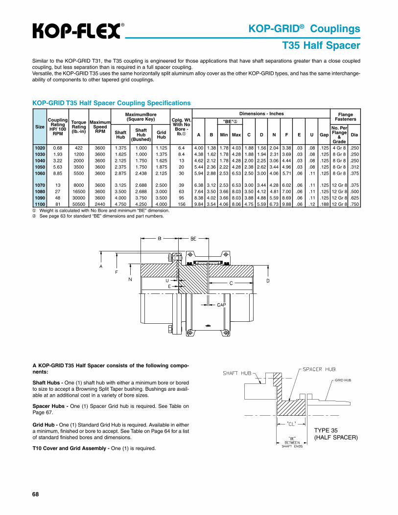
� Weight is calculated with No Bore and minimum “BE” dimension.� See page 63 for standard “BE” dimensions and part numbers.
KOP-GRID T35 Half Spacer Coupling Specifications
Similar to the KOP-GRID T31, the T35 coupling is engineered for those applications that have shaft separations greater than a close coupledcoupling, but less separation than is required in a full spacer coupling.Versatile, the KOP-GRID T35 uses the same horizontally split aluminum alloy cover as the other KOP-GRID types, and has the same interchange-ability of components to other tapered grid couplings.
A KOP-GRID T35 Half Spacer consists of the following compo-nents:
Shaft Hubs - One (1) shaft hub with either a minimum bore or boredto size to accept a Browning Split Taper bushing. Bushings are avail-able at an additional cost in a variety of bore sizes.
Spacer Hubs - One (1) Spacer Grid hub is required. See Table onPage 67.
Grid Hub - One (1) Standard Grid Hub is required. Available in eithera minimum, finished or bore to accept. See Table on Page 64 for a listof standard finished bores and dimensions.
T10 Cover and Grid Assembly - One (1) is required.
KOP-GRID® Couplings
T35 Half Spacer
TYPE 35(HALF SPACER)
eziS
gnilpuoCgnitaR001/PH
MPR
euqroTgnitaR)ni-.bl(
mumixaMdeepS
MPR
eroBmumixaM)yeKerauqS( .tW.glpC
oNhtiW-eroB
.bl �
sehcnI-snoisnemiD egnalFsrenetsaF"EB" �
tfahSbuH
tfahSbuH
)dehsuB(
dirGbuH A B niM xaM C D N F E U paG
reP.oNegnalF
&edarG
aiD
0201 86.0 224 0063 573.1 000.1 521.1 4.6 00.4 83.1 87.1 30.4 88.1 65.1 40.2 83.3 30. 80. 521. 8rG4 052.0301 39.1 0021 0063 526.1 000.1 573.1 4.8 83.4 26.1 87.1 82.4 88.1 49.1 13.2 96.3 30. 80. 521. 8rG8 052.0401 22.3 0002 0063 521.2 057.1 526.1 31 26.4 21.2 87.1 82.4 00.2 52.2 60.3 44.4 30. 80. 521. 8rG8 052.0501 36.5 0053 0063 573.2 057.1 578.1 02 44.5 63.2 22.2 82.4 83.2 26.2 44.3 69.4 30. 80. 521. 8rG8 213.0601 58.8 0055 0063 578.2 834.2 521.2 03 49.5 88.2 35.2 35.6 05.2 00.3 60.4 17.5 60. 11. 521. 8rG8 573.
0701 31 0008 0063 521.3 886.2 005.2 93 83.6 21.3 35.2 35.6 00.3 44.3 82.4 20.6 60. 11. 521. 8rG21 573.0801 72 00561 0063 005.3 886.2 000.3 36 46.7 05.3 66.3 30.8 05.3 21.4 18.4 00.7 60. 11. 521. 8rG21 005.0901 84 00003 0063 000.4 057.3 005.3 59 83.8 20.4 66.3 30.8 88.3 88.4 95.5 96.8 60. 11. 521. 8rG21 526.0011 18 00505 0442 057.4 052.4 000.4 651 48.9 45.3 60.4 60.8 57.4 95.5 37.6 88.9 60. 21. 881. 8rG21 057.

69
®
KOP-GRID T35 CouplingPart Numbers
KOP-GRID Half Spacer Couplings
KOP-GRID® Couplings
T35 Half Spacer
"EB"HTGNELSEHCNI
0201eziS 0301eziS 0401eziS
LC #traP ytQ LC #traP ytQ LC #traP ytQ187.1 526.1 871HPS0201 )1( 526.1 871PHS0301 )1( 526.1 871HPS0401 )1(912.2 260.2 222HPS0201 )1( 260.2 222PHS0301 )1( 260.2 222HPS0401 )1(135.2 573.2 352HPS0201 )1( 573.2 352PHS0301 )1( 573.2 352HPS0401 )1(005.3 443.3 053HPS0401 )1(656.3 005.3 663PHS0301 )1( 005.3 663HPS0401 )1(
"EB"HTGNELSEHCNI
0501eziS 0601eziS 0701eziS
LC #traP ytQ LC #traP ytQ LC #traP ytQ912.2 260.2 222HPS0501 )1(135.2 573.2 352HPS0501 )1( 443.2 352HPS0601 )1( 443.2 352HPS0701 )1(005.3 443.3 053HPS0501 )1(656.3 005.3 663HPS0501 )1( 964.3 663HPS0601 )1( 964.3 663HPS0701 )1(651.6 969.5 616HPS0601 )1( 969.5 616HPS0701 )1(
"EB"HTGNELSEHCNI
0801eziS 0901eziS 0011eziS
LC #traP ytQ LC #traP ytQ LC #traP ytQ135.2656.3 964.3 663HPS0801 )1( 964.3 663HPS0901 )1(260.4 218.3 604HPS0011 )1(839.4 886.4 494HPS0011 )1(000.5 218.4 005HPS0801 )1(651.6 969.5 616HPS0801 )1( 969.5 616HPS0901 )1(
eziSdirGbuH
dirGbuH
dehsuBgnihsuB
tfahSbuH
dehsuBgnihsuB
01TdnarevoC
dirGylbmessA
derepaTdirGtiK
01TrevoC
tiK
01TyrosseccA
tiK
0201 BUH0201 — — GXBUHS0201 G AGC01T0201 DIRG0201 REVOC01T0201 KA01T02010301 BUH0301 — — GXBUHS0301 G AGC01T0301 DIRG0301 REVOC01T0301 KA01T03010401 BUH0401 GXBUH0401 G PXBUHS0401 P AGC01T0401 DIRG0401 REVOC01T0401 KA01T04010501 BUH0501 HXBUH0501 H PXBUHS0501 P AGC01T0501 DIRG0501 REVOC01T0501 KA01T05010601 BUH0601 PXBUH0601 P BXBUHS0601 B AGC01T0601 DIRG0601 REVOC01T0601 KA01T0601
0701 BUH0701 PXBUH0701 P QXBUHS0701 Q AGC01T0701 DIRG0701 REVOC01T0701 KA01T07010801 BUH0801 QXBUH0801 Q QXBUHS0801 Q AGC01T0801 DIRG0801 REVOC01T0801 KA01T08010901 BUH0901 QXBUH0901 Q RXBUHS0901 R AGC01T0901 DIRG0901 REVOC01T0901 KA01T09010011 BUH0011 RXBUH0011 R SXBUHS0011 S AGC01T0011 DIRG0011 REVOC01T0011 KA01T0011

GD-1
GD
Grid Type

GD
GD-2
Grid Type
Couplings Reduce Vibration, Absorb Shockand Compensate for Misalignment.The Power of Torsional DampingThe Lovejoy G-Type Flexible Grid Coupling reduces vibration by as muchas 30%, and cushions shock loads to safeguard your driving and drivenequipment. The flexible nature of the spring-like grid absorbs impact energyby spreading it out over time, thus reducing the magnitude of the peakloads. This is possible because of the progressive contact that occursbetween the curved profile of the hub teeth and the flexible grid. Therefore,as the load increases, more of the tooth comes into contact with the grid,thus supplying superior protection and supreme performance.
Lovejoy G-Type Flexible Grid Couplings are designed for versatility.Common hubs and grids are used within a given size range for bothhorizontal and vertical split cover models. Grid installation and replace-ment is a “snap” at only a fraction of the complete coupling cost.
Benefits of the Grid Coupling include:■ Our 1000 Series Tapered Grid coupling is fully interchangeable with
industry standards.■ Quick installation and easy maintenance reduces labor and downtime
costs.■ Torsionally flexible and resilient - reduces vibration, plus cushions shock
and impact loads.■ Versatile stock components can be used with either horizontal or vertical
covers. Cover fasteners available in either Metric or Imperial sizes.■ High tensile, shot-peened alloy steel grids and precision machined hubs
ensure superior performance and long life.
Top Quality ManufacturingMade from a high tensile alloy steel, the grid spring is carefully formed toshape, then hardened and tempered under controlled conditions. Next, thegrids are shot-peened, compressing the surface molecules and leaving aresidually stressed surface. This process creates a stronger surface incompression.
Any load applied on the coupling in operation must first surmount thecompressive forces created by peening before the tensile stress reachesthe grid. This provides a dramatic increase in rating over other couplingtypes, increases reserve strength for longer life and may permit selectionof a smaller coupling, thus reducing cost.
The Lovejoy Grid spring/hub tooth arrangement has been specificallydesigned for optimum performance and supreme reliability. Not only doesthe hub tooth profile permit progressive loading under torsional shockconditions, but unique root radii are incorporated to significantly improvethe fatigue life of the teeth.
Overview
VERTICALLY SPLIT COVER■ Ideal for higher operating speeds.■ Manufactured from stamped steel.
HORIZONTALLY SPLIT COVER■ Ideal for limited space.■ Allows easy access to grid.■ Well-suited for reversing service.■ Manufactured from die-cast aluminum.
WARNINGYou must refer to page iv for Important Safety Instructions and Precautions forthe selection and use of these products. Failure to follow the instructions andprecautions can result in severe injury or death.
!
FULL SPACER DESIGN■ Ideal for pump applications because
drop-out section allows for pump servicing.■ Used only with horizontally split cover.■ Available in sizes 1020-1090.

GD-3
GD
Grid Type
Grid Coupling Selection ProcessThe selection process for determining the proper grid coupling size requiresusing the charts shown on the following pages. There are three componentsto be selected: two hubs and one cover. When the shaft size of the driverand driven of the application are of the same diameter, the hubs selectedwill be the same. When shaft diameters differ, hubs selected will differaccordingly.
Information necessary before a grid coupling can be selected:■ HP (or KW) and RPM or Torque of driver■ Shaft sizes and type of fit of driver and driven equipment and
corresponding keyways■ Shaft gap■ Physical space limitations■ Application description■ Environmental conditions (i.e. extreme temperature, corrosive
conditions, space limitations)
For applications with high peak loads or brake applications use the formulasgiven on page GD-4 or consult Application Engineering for assistance. Thefollowing information is required for high peak loads or brake applications:
Selection Process
Steps In Selecting A Grid Coupling
Step 1: Determine the Nominal Torque of your application by using thefollowing formula:
Nominal Torque = in-lb = (HP x 63025)RPM
Nm = (KW x 9550)RPM
Step 2: Using the Service Factors Chart 1 (pgs. GD-5-6), select the servicefactor which best corresponds to your application. If you cannotlocate a service factor for your application, choose an appropriatevalue from the General Service Factors Chart 2 (pg. GD-7).
Step 3: Calculate the Design Torque of your application by multiplying theNominal Torque calculated in Step 1 by the Service Factordetermined in Step 2.
Design Torque = Nominal Torque x Service Factor
Step 4: Using the Coupling Torque and Horsepower Ratings Chart 3(pg. GD-7) scan down the torque rating to the first value that isgreater than or equal to the Design Torque calculated in Step 3.
Once this value is located, refer to the corresponding coupling sizein the first column of the Coupling Torque and Horsepower RatingsChart 3 (pg. GD-7).
Refer to the maximum RPM value (pg. GD-7) for the torquecapability to ensure that the application requirements are met. Ifthe requirement is not satisfied at this point, a different cover styleor another type of coupling may be required for the application.Please consult Lovejoy Application Engineering.
Step 5: Compare the application driver/driven shaft sizes to the maximumbore size available on the coupling selected. If coupling bore sizeis not large enough for the shaft diameter, select the next largestcoupling that will accommodate the driver/driven shaft diameters.Refer to Chart 3 (pg. GD-7).
Step 6: Using the Item (UPC) Number Selection charts (pgs. GD-8-10),find the appropriate Bore and Keyway sizes required and locatethe Lovejoy Item (UPC) number. Next locate the appropriateLovejoy Item (UPC) number for the Cover/Grid Assembly Kit.
■ System peak torque and frequency■ Duty cycle■ Brake torque rating
List of Charts provided for Selection:Chart 1 - Service Factors (pgs. GD-5-6)Chart 2 - General Service Factors (pg. GD-7)Chart 3 - Coupling Torque and Horsepower Ratings (pg. GD-7)
Formulas:
Nominal Torque = in-lb = (HP x 63025)RPM
Nm = (KW x 9550)RPM
Design Torque = Nominal Torque x Service Factor

GD
GD-4
Grid Type
Selection Example
A coupling is needed to connect a 50 HP standard electric motor rated at1800 RPM to a rotary compressor. The shaft size of the electric motor(driver) is 1.75 inches and the compressor (driven) is 1.5 inches. The shaftconnections are .75 inches long. There are no special environmentalconditions.
Step 1: Determine the Nominal Torque:Nominal Torque = in-lb = (HP x 63025)
RPMin-lb = (50 x 63025)
1800= 1750.69
Step 2: Using the Service Factors Chart 1 (pgs. GD-5-6), select the servicefactor which best corresponds to your application. The ServiceFactor for an electric motor driving a rotary compressor is 1.25.The value of 1.25 is found under the application categoryCompressor, Rotary, column: Electric Motor in Chart 1.
Step 3: Calculate the Design Torque of your application :Design Torque = Nominal Torque x Service Factor
= 1750.69 x 1.25= 2188.37 in-lb
Step 4: Referencing the Coupling Torque and Horsepower Ratings Chart 3(pg. GD-7), use the Torque Rating column to determine the propercoupling size. Scanning down the Torque Rating column, the firstentry to accommodate the Design Torque value of 2188.37 in-lb issize 1050 with a nominal torque rating of 3500 in-lb. The maximumRPM of 1800 on the electric motor of the application does notexceed the 4500 RPM maximum allowed for this size with thehorizontal cover.
Selection Process
Step 5: Compare the application driver/driven shaft sizes to the maximumbore size available in the coupling selected (pg. GD-7). Theelectric motor (driver) of this application has a shaft size of 1.75inches and the compressor (driven) has a shaft size of 1.5 inches.The G1050 coupling has a maximum bore of 1.875 inches, so itcan accommodate the driver/driven shaft sizes.
Therefore, the proper coupling size for this application is a 1050coupling with a horizontal cover.
Step 6: Using the Item (UPC) Number Selection charts (pgs. GD-8-10),locate the appropriate Lovejoy Item (UPC) numbers.
Locate the Grid Coupling Inch Hubs selection chart (pg. GD-8)The first bore size to be located is for the 1.75 inch shaft on theelectric motor. Scan down the Bore/Keyway column to the 1.75inch bore entry. Read across to the 1050 column to locate theLovejoy Item (UPC) number of 05483.
The second bore size to be located is for the 1.5 inch shaft on thecompressor. Scan down the Bore/Keyway column to the 1.5 inchbore entry. Read across to the 1050 column to locate the LovejoyItem (UPC) number of 05481.
Locate the Grid Coupling Accessory selection chart (pg. GD-10)The cover/grid assembly is selected by scanning accross the GridCoupling Size row to the 1050 entry. Read down to the HorizontalCover/Grid Assembly-Inch row to locate the Lovejoy Item (UPC)number of 05352.
Each of these item (UPC) numbers should be prefixed with theLovejoy Item (UPC) number of 697904.
Selecting A Grid Coupling For High PeakLoads Or Brake Applications
Use this selection method in the following instances: 1) High Peak Loads2 ) Brake Applications (A brake is part of the system but it is not part of theactual coupling.)
Step 1: Calculate the Design Peak Torque using one of the followingequations:Non-Reversing High Peak Torque =
in-lb = System Peak TorqueNm = System Peak Torquein-lb = (System Peak HP x 63025)
RPMNm = (System Peak KW x 9550)
RPMReversing High Peak Torque =
in-lb = 2 x System Peak TorqueNm = 2 X System Peak Torquein-lb = (2 x System Peak HP x 63025)
RPM
Nm = (2 x System Peak KW x 9550)RPM
Occasional Peak Torques (Reversing or Non-Reversing) =in-lb = 0.5 x System Peak TorqueNm = 0.5 x System Peak Torquein-lb = (0.5 x System Peak HP x 63025)
RPMNm = (0.5 x System Peak KW x 9550)
RPM
Step 2: If the application is a brake application and the torque rating of thebrake exceeds the motor torque the brake torque needs to usedwith the application service factor selected in Chart 1 (pg. GD-6-7).
Design Torque = Brake Torque Rating x Service Factor
Step 3: Once the Design Torque has been determined go through steps 4through 6 of the selection process on page GD-4 to determine theproper coupling size.

GD-5
GD
Grid Type
Service Factors Service Factors
Selection Data
Elec
tric
Mot
or w
/ S
tand
ard
Torq
ue
Rec
ipro
catin
g E
ngin
es-4
/5 C
ylin
der
Rec
ipro
catin
g E
ngin
es-6
or m
ore
Cyl
.
Service Factors—Industries Chart 1
Elec
tric
Mot
or w
/ S
tand
ard
Torq
ue
Rec
ipro
catin
g E
ngin
es-4
/5 C
ylin
der
Rec
ipro
catin
g E
ngin
es-6
or m
ore
Cyl
.
Service Factors
Elec
tric
Mot
or w
/ S
tand
ard
Torq
ue
Rec
ipro
catin
g E
ngin
es-4
/5 C
ylin
der
Rec
ipro
catin
g E
ngin
es-6
or m
ore
Cyl
.
Aggregate Processing, Cement,Mining Kilns; Tube, Rod andBall Mills
Dryer, Rotary, Hammermillor Hog,Tumbling Mill or Barrel,Direct or on L.S. Shaft of Red-ucer, with Final Drive of SingleHelical or Herringbone Gears .... 1.75 2.75 2.25
Grizzly, Direct or on L.S. Shaftof Reducer, with Final Driveof Machined Spur Gears ........... 2.00 3.00 2.50
Crushers, Ore or Stone ............... 2.50 * *Brewing and Distilling
Bottle and Can Filling Machines,Brew Kettle ................................ 1.00 2.00 1.50
Cookers, Continuous Duty,Mash Tub .................................. 1.25 2.25 1.75
Lauter Tub ................................... 1.50 2.50 2.00Scale Hopper, Frequent Peaks ... 1.75 2.75 2.25
Clay Working IndustryBrick Press, Briquette Machine,Clay Working Machine,Plug Mill ..................................... 1.75 2.75 2.25
DredgesConveyors ................................... 1.25 2.25 1.75Maneuvering Winch, Pumps(Uniform Load), Utility Winch ..... 1.50 2.50 2.00
Cable Reel, Screen Drive,Stacker ...................................... 1.75 2.75 2.25
Cutter Head, Jig Drive ................. 2.00 3.00 2.50Food Industry
Bottling, Can Filling Machine ...... 1.00 2.00 1.50Cereal Cooker ............................. 1.25 2.25 1.75Beet Slicer, Dough Mixer,Meat Grinder ............................. 1.75 2.75 2.25
LumberRolls, Non-Reversing,Sawdust Conveyor .................... 1.25 2.25 1.75
Band Resaw, Sorting Table ........ 1.50 2.50 2.00Circular Resaw, Cut-off, Planer,Slab Conveyor, Trimmer ........... 1.75 2.75 2.25
Edger, Head Rig, Hog, LogHaul, Rolls, Reversing ............... 2.00 3.00 2.50
Gang Saw (Reciprocating) ................. Refer To LovejoyMetal Rolling Mills1
Soaking Pit Cover Drives - Lift .... 1.00 2.00 1.50
Coilers (Up or Down) ColdMills only, Cooling Beds, MillTables Hot Bed or
Transfer, Non-Reversing ............. 1.50 2.50 2.00Reel Drives, Slitters, Steel Millonly, Wire Drawing Machinery ... 1.75 2.75 2.25
Coilers (Up or Down) Hot Millsonly, Coke Plants DoorOpener, Drawbench, FurnacePushers, Hot and Cold Saws,Ingot Cars, Mill Tables Runout,Non-Reversing, Non-Plugging,Screwdown, Seamless TubeMills -Thrust Block, TubeConveyor Rolls, Reeler, KickOut, Soaking Pit Cover Drives- Travel, Straighteners,
Unscramblers .............................. 2.00 3.00 2.50Coke Plants Pusher RamDrive, ......................................... 2.50 * *
Coke Plants Pusher or LarryCar Traction Drive, FeedRolls-Blooming Mills, Manip-ulators, Mill Tables RoughingBreakdown Mills, Runout,Reversing, Seamless TubeMills Piercer, Sideguards ........... 3.00 * *
Cold Mills, Hot Mills, MerchantMills, Rod Mills, Skelp Mills .............. Refer To Lovejoy
Oil IndustryChiller .......................................... 1.25 2.25 1.75Paraffin Filter Press .................... 1.50 2.50 2.00Oilwell Pumping (not over 150%Peak Torque), Rotary Kiln ......... 2.00 3.00 2.50
Paper MillsBleachers, Coaters, StockPumps, Centrifugal ConstantSpeed ........................................ 1.00 2.00 2.50
Converting Machine, FeltStretcher, Stock Pumps,Centrifugal Frequent SpeedChanges Under Load ................ 1.25 2.25 1.75
Line Shaft, Reel, Rewinder,Winder, Stock Chest, Washer,Thickener ................................... 1.50 2.50 2.00
Beater, Pulper, Calender,Couch, Cylinder, Dryer, PulpGrinder, Fourdrinier, Press,Suction Roll ............................... 1.75 2.75 2.25
Barker Auxiliary, Hydraulic,Mechanical, Barking Drum L.S.Shaft of Reducer with FinalDrive-Helical or HerringboneGear, Cutter, Felt Whipper,Jordan, Log Haul ....................... 2.00 3.00 2.50
Barking Drum L.S. Shaft ofReducer with Final Drive-Machined Spur Gear, Chipper ... 2.50 * *
Barking Drum L.S. Shaft ofReducer with Final Drive-CastTooth Spur Gear ........................ 3.00 * *
Rubber IndustryTire/Tube Press Opener (PeakTorque) ...................................... 1.00 2.00 1.50
Extruder, Mixing Mill, Refineror Sheeter (Five or More inLine), Tuber, Strainer, Pelletizer,Warming Mill (Three or Morein Line) ....................................... 1.75 2.75 2.25
Calender, Mixing Mill, Refineror Sheeter (Three/Four inLine), Warming Mill (One/Twoin Line) ....................................... 2.00 3.00 2.50
Cracker, Plasticator, MixingMill, Refiner or Sheeter(One/Two in line), Intensiveor Banbury Mixer, TireBuilding Machine, Washer ......... 2.50 * *
Sewage Disposal EquipmentBar Screen, Chemical Feeders,Collectors, DewateringScreen, Grit Collector ................ 1.00 2.00 1.50
Sugar IndustryMill Stands, Turbine Driven withall Helical or HerringboneGears ......................................... 1.50 2.50 2.00
Cane Carrier & Leveler, ElectricDrive or Steam Engine Drivewith Helical Herringbone, orSpur Gears with any Prime
Notes: 1. For high peak load applications, please refer to selection process on page GD-4.2. * Indicates that Lovejoy Application Engineering should be consulted with specific requirements.
Caution: Applications involving reciprocating engines and reciprocating driven devices are subject to critical rotational speeds which may damage the coupling and/or connectedequipment. Contact Lovejoy Application Engineering with specific requirements.

GD
GD-6
Grid Type
Service FactorsService FactorsService Factors
Service Factors—Industries and Applications Chart 1, cont.
Selection Data
Notes: 1. For high peak load applications, please refer to selection process on page GD-4.2. If people are transported Lovejoy does not recommend and will not warranty the use of the coupling.3. * Indicates that Lovejoy Application Engineering should be consulted with specific requirements.
Caution: Applications involving reciprocating engines and reciprocating driven devices are subject to critical rotational speeds which may damage the coupling and/or connectedequipment. Contact Lovejoy Application Engineering with specific requirements.
Mover ........................................ 1.75 2.75 2.25Cane Knife & Crusher ................. 2.00 3.00 2.50
Textile IndustryBatcher, Dyeing Machinery,Mangle, Napper, Soaper ........... 1.25 2.25 1.75
Calender, Card Machine, ClothFinishing Machine, Dry Can,Loom, Spinner, Tenter Frame,Winder ....................................... 1.50 2.50 2.00
Knitting Machine ................................... Refer To Lovejoy
ApplicationsAerator ............................................ 2.00 3.00 2.50Agitators
Vertical/Horizontal Screw, Pro-peller, Paddle ............................ 1.00 2.00 1.50
Barge Haul Puller ........................... 1.50 2.50 2.00Blowers
Centrifugal ................................... 1.00 2.00 1.50Lobe, Vane .................................. 1.25 2.25 1.75
Car Dumpers .................................. 2.50 * *Car Pullers ...................................... 1.50 2.50 2.00Clarifier, Classifier ......................... 1.00 2.00 1.50Compressors
Centrifugal, Rotary, Screw .......... 1.00 2.00 1.50Rotary, Lobe or Vane .................. 1.25 2.25 1.75Reciprocating with Flywheel andGear between Compressor andPrime Mover 4 or More Cyl.Single/Double Acting ................. 1.75 2.75 2.25
Reciprocating with flywheeland Gear between Compressorand Prime Mover Cyl. DoubleActing ........................................ 2.00 3.00 2.50
Reciprocating with Flywheel andGear between Compressor andPrime Mover 1/2 Cyl. Single/Double Acting and 3 cyl.Single Acting ............................. 3.00 * *
Reciprocating Direct Connected,Without Flywheels ............................... Refer To Lovejoy
Conveyors2
Apron, Assembly, Belt, Chain,Flight, Screw .............................. 1.00 2.00 1.50
Elec
tric
Mot
or w
/ S
tand
ard
Torq
ue
Rec
ipro
catin
g E
ngin
es-4
/5 C
ylin
der
Rec
ipro
catin
g E
ngin
es-6
or m
ore
Cyl
.
Elec
tric
Mot
or w
/ S
tand
ard
Torq
ue
Rec
ipro
catin
g E
ngin
es-4
/5 C
ylin
der
Rec
ipro
catin
g E
ngin
es-6
or m
ore
Cyl
.
Elec
tric
Mot
or w
/ S
tand
ard
Torq
ue
Rec
ipro
catin
g E
ngin
es-4
/5 C
ylin
der
Rec
ipro
catin
g E
ngin
es-6
or m
ore
Cyl
.
Bucket ......................................... 1.25 2.25 1.75Live Roll, Shaker,Reciprocating ............................ 3.00 * *
Cranes, Hoist1, 2
Slope ........................................... 1.50 2.50 2.00Main or Skip Hoist, Bridge,Travel, Trolley2 .............................................. 1.75 2.75 2.25
Dynamometer ................................. 1.00 2.00 1.50Elevators2
Bucket, Centrifugal, Discharge,Gravity Discharge ....................... 1.25 2.25 1.75Freight or Passenger ..................... NOT APPROVED
Escalators .......................................... NOT APPROVEDExciter, Generator .......................... 1.00 2.00 1.50Extruder, Plastic ............................. 1.50 2.50 2.00Fans
Centrifugal, Forced Draft MotorDriven thru Fluid or Electric SlipClutch ........................................ 1.00 2.00 1.50
Induced Draft with Damper Con-trol or Blade Cleaner ................. 1.25 2.25 1.75
Forced Draft-Across the Linestart, Gas Recirculating ............. 1.50 2.50 2.00
Cooling Tower, Induced Draftwithout Controls ......................... 2.00 3.00 2.50
FeedersApron, Belt, Disc, Screw ............. 1.00 2.00 1.50Reciprocating .............................. 2.50 * *
GeneratorsEven Load ................................... 1.00 2.00 1.50Hoist or Railway Service ............. 1.50 2.50 2.00Welder Load ................................ 2.00 3.00 2.50
Hammermill .................................... 1.75 2.75 2.25Laundrywasher or Tumbler ........... 2.00 3.00 2.50Line Shafts
Any Processing Machinery ......... 1.50 2.50 2.00Machine Tools
Auxiliary, Traverse Drive ............. 1.00 2.00 1.50Main Drive ................................... 1.50 2.50 2.00Bending Roll, Notching Press,Punch Press, Planer, PlateReversing .................................. 1.75 2.75 2.25
Manlifts .............................................. NOT APPROVED
Metal Forming MachinesSlitters ......................................... 1.00 2.00 1.50Wire Winder, Coilers, Uncoilers .. 1.50 2.50 2.00Wire Drawing, Flattening ............. 1.75 2.75 2.25Draw Bench Carriage, MainDrive, Extruder, FormingMachine, Forming Mills ............. 2.00 3.00 2.50
Mixers (see Agitators)Muller .......................................... 1.50 2.50 2.00Concrete ..................................... 1.75 2.75 2.25
Printing Press ................................. 1.50 2.50 2.00Pug Mill ........................................... 1.75 2.75 2.25Pulverizers
Roller ........................................... 1.50 2.50 2.00Hammermill, Hog ........................ 1.75 2.75 2.25
PumpsCentrifugal Constant Speed ........ 1.00 2.00 1.50Centrifugal Frequent SpeedChanges under Load, Descaling,w/ Accumulators, Gear, Rotary,Vane .......................................... 1.25 2.25 1.75
Reciprocating, 3 or moreCylinders ................................... 1.50 2.50 2.00
Reciprocating, 2 Cyl. DoubleActing ........................................ 1.75 2.75 2.25
Reciprocating, 2 Cyl. SingleActing ........................................ 2.00 3.00 2.50
Reciprocating, 1 Cyl. Single/Double Acting ............................ 3.00 * *
ScreensAir Washing, Water ..................... 1.00 2.00 1.50Rotary Coal, Sand ....................... 1.50 2.50 2.00Grizzly ......................................... 2.00 3.00 2.50Vibrating ...................................... 2.50 * *
Ski Tows, Lifts ................................... NOT APPROVEDSteering Gear ................................. 1.00 2.00 1.50Stoker .............................................. 1.00 2.00 1.50Tumbling Barrel ............................. 1.75 2.75 2.25Winch, Maneuvering
Dredge, Marine .......................... 1.50 2.50 2.00Windlass ......................................... 1.50 2.50 2.00Woodworking Machinery .............. 1.00 2.00 1.50Work Lift Platforms ........................... NOT APPROVED
GD-7
GD
Grid Type
General Service Factors Chart 2Typical Applications for Electric Motor Typical
or Turbine Driven Equipment Service Factor
Constant Torque such as CentrifugalPumps, Blowers, and Compressors. 1.0
Continuous Duty with some torquevariations including Printing Presses, 1.5
Extruders, Forced Draft Fans.
Light shock loads from BriquettingMachine, Rubber Calender, or 2.0
Crane and Hoist
Moderate shock loading as expectedfrom a Car Dumper, Reciprocating 2.5
Feeder, or Vibrating Screen.
Heavy Shock load with somenegative torques from Crushers, 3.0Manipulators and Braking Drum.
Applications like Reciprocating ConsultCompressors with frequent torque Lovejoyreversals which do not necessarily Application
cause reverse rotations. Engineering
Selection Data
Torque and Horsepower Ratings Chart 3Basic HP Ratings Horizontal Vertical@ Varying RPM Torque Ratings Maximum Bore Max RPM Max RPM
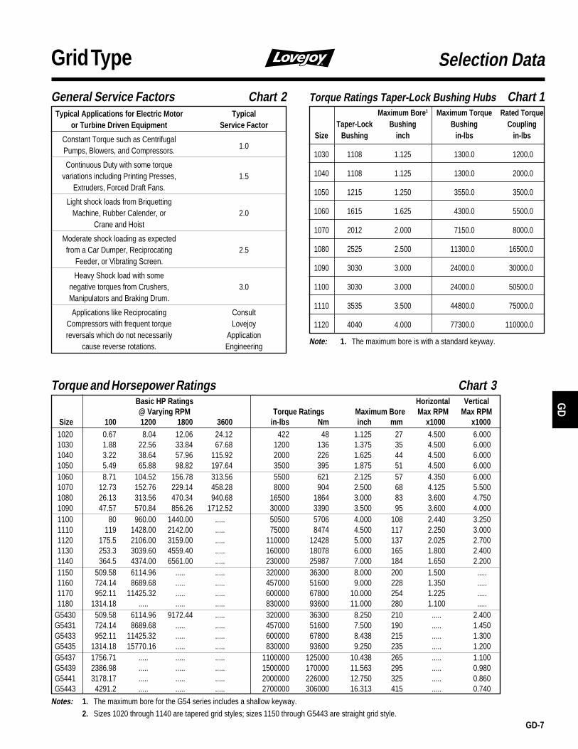
Size 100 1200 1800 3600 in-lbs Nm inch mm x1000 x10001020 0.67 8.04 12.06 24.12 422 48 1.125 27 4.500 6.0001030 1.88 22.56 33.84 67.68 1200 136 1.375 35 4.500 6.0001040 3.22 38.64 57.96 115.92 2000 226 1.625 44 4.500 6.0001050 5.49 65.88 98.82 197.64 3500 395 1.875 51 4.500 6.0001060 8.71 104.52 156.78 313.56 5500 621 2.125 57 4.350 6.0001070 12.73 152.76 229.14 458.28 8000 904 2.500 68 4.125 5.5001080 26.13 313.56 470.34 940.68 16500 1864 3.000 83 3.600 4.7501090 47.57 570.84 856.26 1712.52 30000 3390 3.500 95 3.600 4.0001100 80 960.00 1440.00 .....aa 50500 5706 4.000 108 2.440 3.2501110 119 1428.00 2142.00 .....aa 75000 8474 4.500 117 2.250 3.0001120 175.5 2106.00 3159.00 .....aa 110000 12428 5.000 137 2.025 2.7001130 253.3 3039.60 4559.40 .....aa 160000 18078 6.000 165 1.800 2.4001140 364.5 4374.00 6561.00 .....aa 230000 25987 7.000 184 1.650 2.2001150 509.58 6114.96 .....aa .....aa 320000 36300 8.000 200 1.500 .....a1160 724.14 8689.68 .....aa .....aa 457000 51600 9.000 228 1.350 .....a1170 952.11 11425.32 .....aa .....aa 600000 67800 10.000 254 1.225 .....a1180 1314.18 .....aa .....aa .....aa 830000 93600 11.000 280 1.100 .....a
G5430 509.58 6114.96 9172.44 .....aa 320000 36300 8.250 210 .....a 2.400G5431 724.14 8689.68 .....aa .....aa 457000 51600 7.500 190 .....a 1.450G5433 952.11 11425.32 .....aa .....aa 600000 67800 8.438 215 .....a 1.300G5435 1314.18 15770.16 .....aa .....aa 830000 93600 9.250 235 .....a 1.200G5437 1756.71 .....aa .....aa .....aa 1100000 125000 10.438 265 .....a 1.100G5439 2386.98 .....aa .....aa .....aa 1500000 170000 11.563 295 .....a 0.980G5441 3178.17 .....aa .....aa .....aa 2000000 226000 12.750 325 .....a 0.860G5443 4291.2 .....aa .....aa .....aa 2700000 306000 16.313 415 .....a 0.740
Notes: 1. The maximum bore for the G54 series includes a shallow keyway.2. Sizes 1020 through 1140 are tapered grid styles; sizes 1150 through G5443 are straight grid style.
Torque Ratings Taper-Lock Bushing Hubs Chart 1Maximum Bore1 Maximum Torque Rated Torque
Taper-Lock Bushing Bushing CouplingSize Bushing inch in-lbs in-lbs
1030 1108 1.125 1300.0 1200.0
1040 1108 1.125 1300.0 2000.0
1050 1215 1.250 3550.0 3500.0
1060 1615 1.625 4300.0 5500.0
1070 2012 2.000 7150.0 8000.0
1080 2525 2.500 11300.0 16500.0
1090 3030 3.000 24000.0 30000.0
1100 3030 3.000 24000.0 50500.0
1110 3535 3.500 44800.0 75000.0
1120 4040 4.000 77300.0 110000.0
Note: 1. The maximum bore is with a standard keyway.
GD
GD-8
Grid Type
Bore Keyway 1020 1030 1040 1050 1060 1070 1080 1090 1100 1110 1120 1130 1140
SOLID 05231 05232 05233 05234 05235 05236 05237 05238 05239 05240 05241 05242 052431/2 1/8 x 1/16 05458 ..... ..... ..... ..... ..... ..... ..... ..... ..... ..... ..... .....5/8 3/16 x 3/32 05459 05464 ..... ..... ..... ..... ..... ..... ..... ..... ..... ..... .....3/4 3/16 x 3/32 05460 05465 06140 ..... ..... ..... ..... ..... ..... ..... ..... ..... .....7/8 3/16 x 3/32 05461 05466 05471 06141 06142 ..... ..... ..... ..... ..... ..... ..... .....
15/16 1/4 x 1/8 06100 06101 06103 06106 ..... ..... ..... ..... ..... ..... ..... ..... .....
1 1/4 x 1/8 05462 05467 05472 06107 06112 ..... ..... ..... ..... ..... ..... ..... .....11/8 1/4 x 1/8 05463 05468 05473 05478 06113 06144 07364 ..... ..... ..... ..... ..... .....13/16 1/4 x 1/8 ..... 06102 06104 06108 06114 ..... ..... ..... ..... ..... ..... ..... .....11/4 1/4 x 1/8 ..... 05469 05474 05479 06115 06145 06148 ..... ..... ..... ..... ..... .....13/8 5/16 x 5/32 ..... 05470 05475 05480 05485 06119 06149 ..... ..... ..... ..... ..... .....17/16 3/8 x 3/16 ..... ..... 06105 06109 06116 06120 ..... ..... ..... ..... ..... ..... .....11/2 3/8 x 3/16 ..... ..... 05476 05481 05486 06121 ..... ..... ..... ..... ..... ..... .....15/8 3/8 x 3/16 ..... ..... 05477 05482 05487 05492 06150 ..... ..... ..... ..... ..... .....
111/16 3/8 x 3/16 ..... ..... ..... 06110 06117 06122 ..... ..... ..... ..... ..... ..... .....13/4 3/8 x 3/16 ..... ..... ..... 05483 05488 05493 06124 ..... ..... ..... ..... ..... .....
113/16 1/2 x 1/4 ..... ..... ..... 06111 06118 06123 06125 ..... ..... ..... ..... ..... .....17/8 1/2 x 1/4 ..... ..... ..... 05484 05489 05494 06126 06154 ..... ..... ..... ..... .....
115/161/2 x 1/4 ..... ..... ..... ..... 06143 06146 06151 ..... ..... ..... ..... ..... .....
2 1/2 x 1/4 ..... ..... ..... ..... 05490 05495 05500 06155 ..... ..... ..... ..... .....21/8 1/2 x 1/4 ..... ..... ..... ..... 05491 05496 05501 06127 ..... ..... ..... ..... .....23/16 1/2 x 1/4 ..... ..... ..... ..... ..... 06147 06152 06156 ..... ..... ..... ..... .....21/4 1/2 x 1/4 ..... ..... ..... ..... ..... 05497 05502 06128 ..... ..... ..... ..... .....23/8 5/8 x 5/16 ..... ..... ..... ..... ..... 05498 05503 06129 ..... ..... ..... ..... .....21/2 5/8 x 5/16 ..... ..... ..... ..... ..... 05499 05504 05509 05519 ..... ..... ..... .....25/8 5/8 x 5/16 ..... ..... ..... ..... ..... ..... 05505 05510 05520 ..... ..... ..... .....23/4 5/8 x 5/16 ..... ..... ..... ..... ..... ..... 05506 05511 05521 ..... ..... ..... .....27/8 3/4 x 3/8 ..... ..... ..... ..... ..... ..... 05507 05512 05522 ..... ..... ..... .....
215/163/4 x 3/8 ..... ..... ..... ..... ..... ..... 06153 06157 ..... ..... ..... ..... .....
3 3/4 x 3/8 ..... ..... ..... ..... ..... ..... 05508 05513 05523 05532 05542 ..... .....31/8 3/4 x 3/8 ..... ..... ..... ..... ..... ..... ..... 05514 05524 05533 05543 ..... .....31/4 3/4 x 3/8 ..... ..... ..... ..... ..... ..... ..... 05515 05525 05534 05544 ..... .....33/8 7/8 x 7/16 ..... ..... ..... ..... ..... ..... ..... 05516 05526 05535 05545 ..... .....37/16 7/8 x 7/16 ..... ..... ..... ..... ..... ..... ..... 06158 ..... ..... ..... ..... .....31/2 7/8 x 7/16 ..... ..... ..... ..... ..... ..... ..... 05517 05527 05536 05546 05553 .....35/8 7/8 x 7/16 ..... ..... ..... ..... ..... ..... ..... ..... 05528 05537 05547 05554 .....33/4 7/8 x 7/16 ..... ..... ..... ..... ..... ..... ..... ..... 05529 05538 05548 05555 .....37/8 1" x 1/2 ..... ..... ..... ..... ..... ..... ..... ..... 05530 05539 05549 05556 05562
4 1" x 1/2 ..... ..... ..... ..... ..... ..... ..... ..... 05531 05540 05550 05557 0556341/2 1" x 1/2 ..... ..... ..... ..... ..... ..... ..... ..... ..... 05541 05551 05558 055645 11/4 x 5/8 ..... ..... ..... ..... ..... ..... ..... ..... ..... ..... 05552 05559 05565
51/2 11/4 x 5/8 ..... ..... ..... ..... ..... ..... ..... ..... ..... ..... ..... 05560 05566
6 11/2 x 3/4 ..... ..... ..... ..... ..... ..... ..... ..... ..... ..... ..... 05561 05567 61/2 11/2 x 3/4 ..... ..... ..... ..... ..... ..... ..... ..... ..... ..... ..... ..... 05568
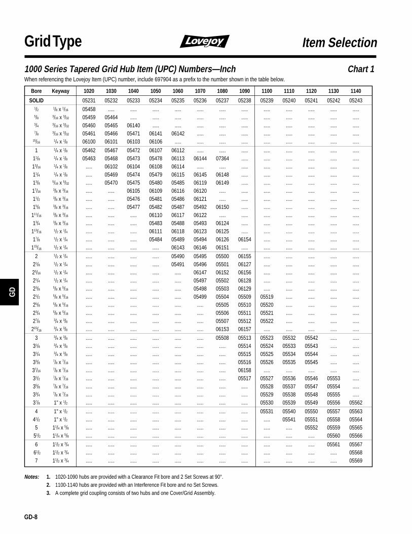
7 11/2 x 3/4 ..... ..... ..... ..... ..... ..... ..... ..... ..... ..... ..... ..... 05569
Notes: 1. 1020-1090 hubs are provided with a Clearance Fit bore and 2 Set Screws at 90°.2. 1100-1140 hubs are provided with an Interference Fit bore and no Set Screws.3. A complete grid coupling consists of two hubs and one Cover/Grid Assembly.
Item Selection
1000 Series Tapered Grid Hub Item (UPC) Numbers—Inch Chart 1When referencing the Lovejoy Item (UPC) number, include 697904 as a prefix to the number shown in the table below.
GD-9
GD
Grid Type
Bore Keyway 1020 1030 1040 1050 1060 1070 1080 1090
14 5 x 2.3 05780 ..... ..... ..... ..... ..... ..... .....15 5 x 2.3 05781 ..... ..... ..... ..... ..... ..... .....16 5 x 2.3 05782 ..... ..... ..... ..... ..... ..... .....19 6 x 2.8 05783 05788 ..... ..... ..... ..... ..... .....20 6 x 2.8 05784 05789 ..... ..... ..... ..... ..... .....22 6 x 2.8 05785 05790 ..... ..... ..... ..... ..... .....24 8 x 3.3 05786 05791 05797 ..... ..... ..... ..... .....25 8 x 3.3 05787 05792 05798 ..... ..... ..... ..... .....
28 8 x 3.3 ..... 05793 05799 05805 ..... ..... ..... .....30 8 x 3.3 ..... 05794 05800 05806 ..... ..... ..... .....32 10 x 3.3 ..... 05795 05801 05807 ..... ..... ..... .....35 10 x 3.3 ..... 05796 05802 05808 05812 05817 ..... .....38 10 x 3.3 ..... ..... 05803 05809 05813 05818 05823 .....42 12 x 3.3 ..... ...... 05804 05810 05814 05819 05824 0583048 14 x 3.8 ..... ..... ..... 05811 05815 05820 05825 0583155 16 x 4.3 ..... ..... ..... ..... 05816 05821 05826 0583260 18 x 4.4 ..... ..... ..... ..... ..... 05822 05827 0583370 20 x 4.9 ..... ..... ..... ..... ..... ..... 05828 0583480 22 x 5.4 ..... ..... ..... ..... ..... ..... 05829 0583585 22 x 5.4 ..... ..... ..... ..... ..... ..... ..... 0583695 25 x 5.4 ..... ..... ..... ..... ..... ..... ..... 05837
Notes: 1. 1020-1090 hubs are provided with a Clearance Fit bore and 2 Set Screws at 90°.2. A complete grid coupling consists of two hubs and one Cover/Grid Assembly.
G2000 Series Tapered Grid Hub Item (UPC) Numbers—Metric Chart 2When referencing the Lovejoy Item (UPC) number, include 697904 as a prefix to the number shown in the table below.
Item Selection
1000 Series Taper-Lock Grid Hub Item (UPC) Numbers Chart 3When referencing the Lovejoy Item (UPC) Number, include 697904 as a prefix to the number shown in the table below.
Taper-Lock Hub 1030 1040 1050 1060 1070 1080 1090 1100 1110 1120
UNC Thread 06841 06842 06843 06844 06845 06846 06847 06848 06849 06850
BSW Thread 06851 06852 06853 06854 06855 06856 06857 06858 06859 06860

GD
GD-10
Grid Type Item Selection
Sizes ➞ 1020 1030 1040 1050 1060 1070 1080 1090 1100 1110 1120 1130 1140
Grid Only 05244 05245 05246 05247 05248 05249 05250 05251 05252 05253 05254 05255 05256
Horizontal Design:Cover/Grid Assembly-Metric 05366 05367 05368 05369 05370 05371 05372 05373 05374 05375 05376 05377 05378Cover/Grid Assembly-Inch 05349 05350 05351 05352 05353 05354 05355 05356 05357 05358 05359 05360 05361Cover Set - Metric 05290 05291 05292 05293 05294 05295 05296 05297 05298 05299 05300 05301 05302Cover Set - Inch 05273 05274 05275 05276 05277 05278 05279 05280 05281 05282 05283 05284 05285Seal Kit 05176 05177 05178 05179 05180 05181 05182 05183 05184 05185 05186 05187 05188Cover Hardware - Metric 05210 05210 05210 05211 05211 05212 05212 05212 05213 05213 05214 05214 05214Cover Hardware - Inch 05433 05433 05433 05434 05434 05435 05435 05435 05436 05436 05437 05437 05437
Vertical Design:Cover/Grid Assembly-Metric 05400 05401 05402 05403 05404 05405 05406 05407 05408 05409 05410 05411 05412Cover/Grid Assembly-Inch 05383 05384 05385 05386 05387 05388 05389 05390 05391 05392 05393 05394 05395Cover Set - Metric 05328 05329 05330 05331 05332 05333 05334 05335 05336 05337 05338 05339 05340Cover Set - Inch 05307 05308 05309 05310 05311 05312 05313 05314 05315 05316 05317 05318 05319Seal Kit 05189 05190 05191 05192 05193 05194 05195 05196 05197 05198 05199 05200 05201Cover Hardware - Metric 05215 05216 05216 05217 05217 05217 05218 05218 05219 05219 05220 05221 05222Cover Hardware - Inch 05442 05443 05443 05444 05444 05444 05445 05445 05446 05446 05447 05448 05449
Notes: 1. “Cover/Grid Assembly” includes ALL components of the coupling, other than the hubs. The terms “metric” and “inch” refer to hardware.2. “Cover Set” includes all of the above items except the Grid spring.3. “Seal Kit” contains rubber seals, gasket(s) and lube plugs.4. “Cover Hardware” includes the fasteners that hold the cover together.5. Grease packets are included with all Cover Sets and Cover/Grid assemblies thru size G20%
Item (UPC) Numbers—1000 Series Tapered Grid Component Parts Chart 3When referencing the Lovejoy Item (UPC) number, include 697904 as a prefix to the number shown in the table below. A complete Grid Coupling consists of twohubs and one Cover/Grid Assembly.
Item (UPC) Numbers—Straight Grid Component Parts Chart 4When referencing the Lovejoy Item (UPC) number, include 697904 as a prefix to the number shown in the table below. A complete Grid Coupling consists oftwo hubs and one Cover/Grid Assembly.
Sizes ➞ 1150 1160 1170 1180 G5430 G5431 G5433 G5435 G5437 G5439 G5441 G5443
Horizontal Design: Vertical Design:
Hub 73mm RSB 05587 ..... ..... ..... 05265 ..... ..... ..... ..... ..... ..... .....Hub 100mm RSB ..... 05589 05591 ..... ..... ..... ..... ..... ..... ..... ..... .....Hub Free 100mm RSB ..... ..... ..... ..... ..... 05266 05267 ..... ..... ..... ..... .....Hub Fixed 100mm RSB ..... ..... ..... ..... ..... 06764 06765 ..... ..... ..... ..... .....Hub 125mm RSB ..... ..... ..... 05593 ..... ..... ..... ..... ..... ..... ..... .....Hub Free 125mm RSB ..... ..... ..... ..... ..... ..... ..... 05268 05269 ..... ..... .....Hub Fixed 125mm RSB ..... ..... ..... ..... ..... ..... ..... 06766 06767 ..... ..... .....Hub Free 150mm RSB ..... ..... ..... ..... ..... ..... ..... ..... ..... 05270 05271 .....Hub Fixed 150mm RSB ..... ..... ..... ..... ..... ..... ..... ..... ..... 06768 06769 .....Hub Free 175mm RSB ..... ..... ..... ..... ..... ..... ..... ..... ..... ..... ..... 05272Hub Fixed 175mm RSB ..... ..... ..... ..... ..... ..... ..... ..... ..... ..... ..... 06770
Grid Only 05257 05258 05259 05260 05257 05258 05259 05260 05261 05262 05263 05264Cover/Grid Assembly-Metric 05379 05380 05381 05382 05413 05414 05415 05416 05417 05418 05419 05420Cover/Grid Assembly-Inch 05362 05363 05364 05365 .... ..... ..... ..... ..... ..... ..... .....Cover Set - Metric 05303 05304 05305 05306 05341 05342 05343 05344 05345 05346 05347 05348Cover Set - Inch 05286 05287 05288 05289 ..... ..... ..... ..... ..... ..... ..... .....Seal Kit 05425 05426 05427 05428 05202 05203 05204 05205 05206 05207 05208 05209Cover Hardware - Metric 05429 05429 05430 05430 05223 05224 05225 05226 05227 05228 05229 05230Cover Hardware - Inch 05438 05438 05439 05439 ..... ..... ..... ..... ..... ..... ..... .....
Notes: 1. “Cover/Grid Assembly” includes ALL components of the coupling, other than the hubs. The terms “metric” and “inch” refer to hardware.2. “Cover Set” includes all of the above items except the Grid spring.3. “Seal Kit” contains rubber seals, gasket(s) and lube plugs.4. “Cover Hardware” includes the fasteners that hold the cover together.5. Grease packets are included with all Cover Sets and Cover/Grid assemblies thru size G2090.

GD-11
GD
Grid Type
Interchange Chart
Performance Data
Horizontal VerticalSplit Cover Split Cover
Lovejoy Falk Morse/Browning Dodge Kop-Flex Falk Morse/Browning Dodge Kop-FlexSize Steelflex Grid-Flex Grid-Lign Kop-Grid Steelflex Grid-Flex Grid-Lign Kop-Grid1020 1020T10 GF2020H 1020T10 1020H 1020T20 GF2020V 1020T20 1020V1030 1030T10 GF2030H 1030T10 1030H 1030T20 GF2030V 1030T20 1030V1040 1040T10 GF2040H 1040T10 1040H 1040T20 GF2040V 1040T20 1040V1050 1050T10 GF2050H 1050T10 1050H 1050T20 GF2050V 1050T20 1050V1060 1060T10 GF2060H 1060T10 1060H 1060T20 GF2060V 1060T20 1060V1070 1070T10 GF2070H 1070T10 1070H 1070T20 GF2070V 1070T20 1070V1080 1080T10 GF2080H 1080T10 1080H 1080T20 GF2080V 1080T20 1080V1090 1090T10 GF2090H 1090T10 1090H 1090T20 GF2090V 1090T20 1090V1100 1100T10 GF2100H 1100T10 1100H 1100T20 GF2100V 1100T20 1100V1110 1110T10 GF2110H 1110T10 1110H 1110T20 GF2110V 1110T20 1110V1120 1120T10 GF2120H 1120T10 1120H 1120T20 GF2120V 1120T20 1120V1130 1130T10 GF2130H 1130T10 1130H 1130T20 GF2130V 1130T20 1130V1140 1140T10 GF2140H 1140T10 1140H 1140T20 GF2140V 1140T20 1140V1150 1150T10 ..... ..... ..... ..... ..... ..... .....1160 1160T10 ..... ..... ..... ..... ..... ..... .....1170 1170T10 ..... ..... ..... ..... ..... ..... .....1180 1180T10 ..... ..... ..... ..... ..... ..... .....
G5430 ..... ..... ..... ..... 1150T20 ..... ..... .....G5431 ..... ..... ..... ..... 1160T20 ..... ..... .....G5433 ..... ..... ..... ..... 1170T20 ..... ..... .....
Note: 1020 to 1140 interchanges with Falk. 1150 and above are not direct interchanges with Falk.
Torque and Horsepower RatingsBasic HP Ratings Horizontal Vertical@ Varying RPM Torque Ratings Maximum Bore Max RPM Max RPM
Size 100 1200 1800 3600 in-lbs Nm inch mm x1000 x10001020 0.67 8.04 12.06 24.12 422 48 1.125 27 4.500 6.0001030 1.88 22.56 33.84 67.68 1200 136 1.375 35 4.500 6.0001040 3.22 38.64 57.96 115.92 2000 226 1.625 44 4.500 6.0001050 5.49 65.88 98.82 197.64 3500 395 1.875 51 4.500 6.0001060 8.71 104.52 156.78 313.56 5500 621 2.125 57 4.350 6.0001070 12.73 152.76 229.14 458.28 8000 904 2.500 68 4.125 5.5001080 26.13 313.56 470.34 940.68 16500 1864 3.000 83 3.600 4.7501090 47.57 570.84 856.26 1712.52 30000 3390 3.500 95 3.600 4.0001100 80.00 960.00 1440.00 .....aa 50500 5706 4.000 108 2.440 3.2501110 119.00 1428.00 2142.00 .....aa 75000 8474 4.500 117 2.250 3.0001120 175.50 2106.00 3159.00 .....aa 110000 12428 5.000 137 2.025 2.7001130 253.30 3039.60 4559.40 .....aa 160000 18078 6.000 165 1.800 2.4001140 364.50 4374.00 6561.00 .....aa 230000 25987 7.000 184 1.650 2.2001150 509.58 6114.96 .....aa .....aa 320000 36300 8.000 200 1.500 .....a1160 724.14 8689.68 .....aa .....aa 457000 51600 9.000 228 1.350 .....a1170 952.11 11425.32 .....aa .....aa 600000 67800 10.000 254 1.225 .....a1180 1314.18 .....aa .....aa .....aa 830000 93600 11.000 280 1.100 .....a
G5430 509.58 6114.96 9172.44 .....aa 320000 36300 8.250 210 .....a 2.400G5431 724.14 8689.68 .....aa .....aa 457000 51600 7.500 190 .....a 1.450G5433 952.11 11425.32 .....aa .....aa 600000 67800 8.438 215 .....a 1.300G5435 1314.18 15770.16 .....aa .....aa 830000 93600 9.250 235 .....a 1.200G5437 1756.71 .....aa .....aa .....aa 1100000 125000 10.438 265 .....a 1.100G5439 2386.98 .....aa .....aa .....aa 1500000 170000 11.563 295 .....a 0.980G5441 3178.17 .....aa .....aa .....aa 2000000 226000 12.750 325 .....a 0.860G5443 4291.2 .....aa .....aa .....aa 2700000 306000 16.313 415 .....a 0.740
Note: The maximum bore for 5430 to G5443 includes a shallow keyway.

GD
GD-12
Grid Type Performance Data
Misalignment CapacityMax. Installation Operating Normal
Misalignment Misalignment GapCoupling Parallel Angular Parallel Angular ±10 %
Size P X-Y P X-Y G
1020 0.006 0.003 0.012 0.010 0.1251030 0.006 0.003 0.012 0.012 0.1251040 0.006 0.003 0.012 0.013 0.1251050 0.008 0.004 0.016 0.016 0.1251060 0.008 0.005 0.016 0.018 0.1251070 0.008 0.005 0.016 0.020 0.1251080 0.008 0.006 0.016 0.024 0.1251090 0.008 0.007 0.016 0.028 0.125
1100 0.010 0.008 0.020 0.033 0.1881110 0.010 0.009 0.020 0.036 0.1881120 0.011 0.010 0.022 0.040 0.2501130 0.011 0.012 0.022 0.047 0.2501140 0.011 0.013 0.022 0.053 0.2501150 0.010 0.014 ..... ..... 0.2481160 0.010 0.014 ..... ..... 0.2481170 0.010 0.014 ..... ..... 0.2481180 0.010 0.014 ..... ..... 0.248
G5430 0.010 0.014 ..... ..... 0.098G5431 0.010 0.014 ..... ..... 0.118G5433 0.010 0.014 ..... ..... 0.118G5435 0.010 0.014 ..... ..... 0.118G5437 0.010 0.014 ..... ..... 0.118G5439 0.010 0.014 ..... ..... 0.118G5441 0.014 0.020 ..... ..... 0.236G5443 0.014 0.020 ..... ..... 0.236
Note: Misalignment ratings pertain to both standard and spacer grid couplings.
PARALLEL MISALIGNMENT
NORMAL GAP
ANGULAR MISALIGNMENT
Parallel: The movement of the grid in the hubgrooves accommodates parallel misalignmentand still permits full functioning of the grid-groove action in damping out shock andvibration.
Angular: Under angular misalignment, thegrid-groove design permits a rocking andsliding action of the grid and hubs without anyloss of power through the resilient grid.
Axial: End float is permitted for both drivingand driven members because the grid slidesfreely in the grooves.
Misalignment Capacity:
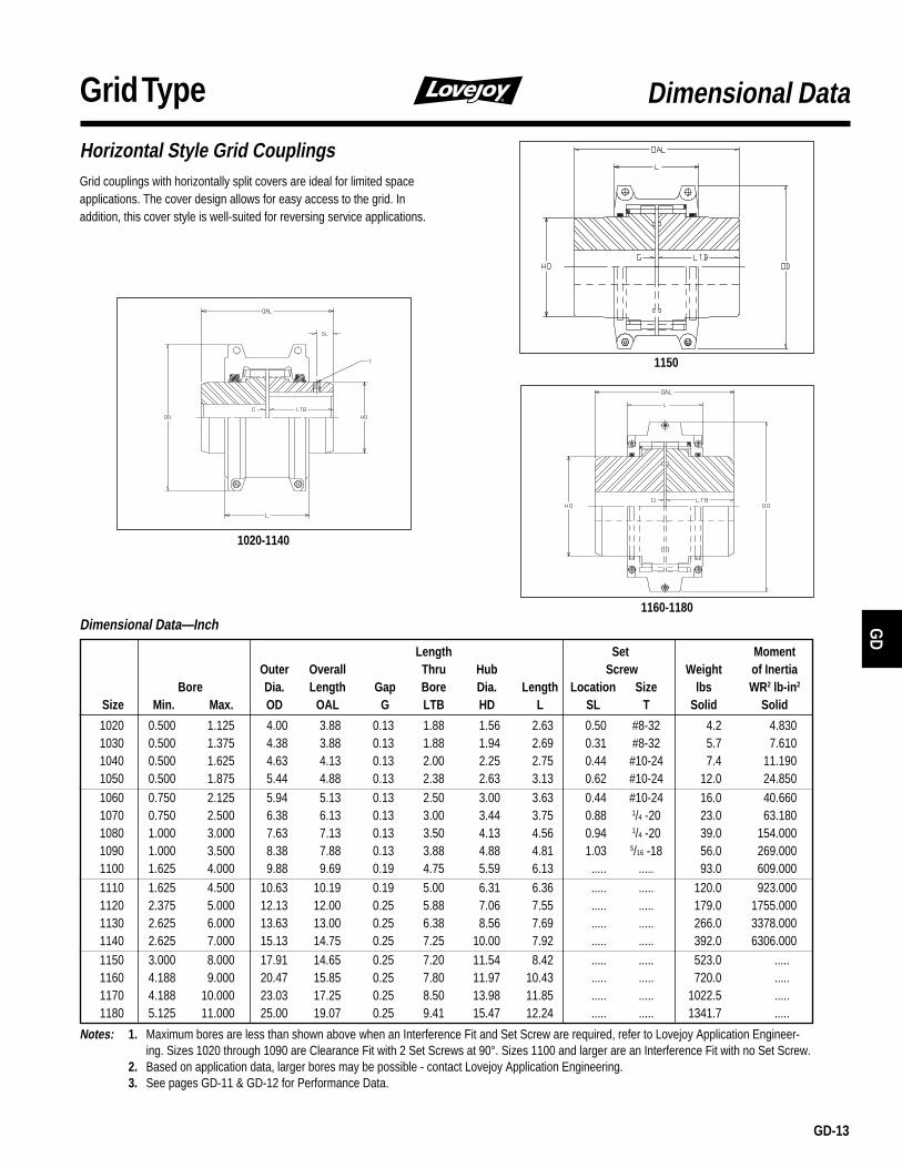
GD-13
GD
Grid Type
Horizontal Style Grid CouplingsGrid couplings with horizontally split covers are ideal for limited spaceapplications. The cover design allows for easy access to the grid. Inaddition, this cover style is well-suited for reversing service applications.
Dimensional Data
Dimensional Data—Inch
Length Set MomentOuter Overall Thru Hub Screw Weight of Inertia
Bore Dia. Length Gap Bore Dia. Length Location Size lbs WR2 lb-in2
Size Min. Max. OD OAL G LTB HD L SL T Solid Solid
1020 0.500 1.125 4.00 3.88 0.13 1.88 1.56 2.63 0.50 #8-32 4.2 4.8301030 0.500 1.375 4.38 3.88 0.13 1.88 1.94 2.69 0.31 #8-32 5.7 7.6101040 0.500 1.625 4.63 4.13 0.13 2.00 2.25 2.75 0.44 #10-24 7.4 11.1901050 0.500 1.875 5.44 4.88 0.13 2.38 2.63 3.13 0.62 #10-24 12.0 24.8501060 0.750 2.125 5.94 5.13 0.13 2.50 3.00 3.63 0.44 #10-24 16.0 40.6601070 0.750 2.500 6.38 6.13 0.13 3.00 3.44 3.75 0.88 1/4 -20 23.0 63.1801080 1.000 3.000 7.63 7.13 0.13 3.50 4.13 4.56 0.94 1/4 -20 39.0 154.0001090 1.000 3.500 8.38 7.88 0.13 3.88 4.88 4.81 1.03 5/16 -18 56.0 269.0001100 1.625 4.000 9.88 9.69 0.19 4.75 5.59 6.13 ..... ..... 93.0 609.000
1110 1.625 4.500 10.63 10.19 0.19 5.00 6.31 6.36 ..... ..... 120.0 923.0001120 2.375 5.000 12.13 12.00 0.25 5.88 7.06 7.55 ..... ..... 179.0 1755.0001130 2.625 6.000 13.63 13.00 0.25 6.38 8.56 7.69 ..... ..... 266.0 3378.0001140 2.625 7.000 15.13 14.75 0.25 7.25 10.00 7.92 ..... ..... 392.0 6306.0001150 3.000 8.000 17.91 14.65 0.25 7.20 11.54 8.42 ..... ..... 523.0 .....A1160 4.188 9.000 20.47 15.85 0.25 7.80 11.97 10.43 ..... ..... 720.0 .....A1170 4.188 10.000 23.03 17.25 0.25 8.50 13.98 11.85 ..... ..... 1022.5 .....A1180 5.125 11.000 25.00 19.07 0.25 9.41 15.47 12.24 ..... ..... 1341.7 .....A
Notes: 1. Maximum bores are less than shown above when an Interference Fit and Set Screw are required, refer to Lovejoy Application Engineer-ing. Sizes 1020 through 1090 are Clearance Fit with 2 Set Screws at 90°. Sizes 1100 and larger are an Interference Fit with no Set Screw.
2. Based on application data, larger bores may be possible - contact Lovejoy Application Engineering.3. See pages GD-11 & GD-12 for Performance Data.
1020-1140
1160-1180
1150

GD
GD-14
Grid Type
Vertical Style Grid CouplingsVertically split cover design grid couplings are ideal for applications withhigher operating speeds. Sizes G1020-1140 and G5430 are stamped steel,sizes G5431 and above are cast iron. This cover style offers superiorprotection and supreme performance.
Dimensional Data
Dimensional Data—Inch
Length Set MomentOuter Overall Thru Hub Flange Flange Screw Weight of Inertia
Bore Dia. Length Gap Bore Dia. Dia. Length Length Max Location Size lbs WR2 lb.in2
Size Min. Max. OD OAL G LTB HD FD L FL R SL T Solid Solid1020 0.500 1.125 4.38 3.88 0.13 1.88 1.56 2.50 0.96 0.38 1.88 0.50 #8-32 4.3 5.3201030 0.500 1.375 4.75 3.88 0.13 1.88 1.94 2.88 1.00 0.38 1.88 0.31 #8-32 5.7 7.9901040 0.500 1.625 5.06 4.13 0.13 2.00 2.25 3.25 1.03 0.38 2.00 0.44 #10-24 7.4 11.9901050 0.500 1.875 5.81 4.88 0.13 2.38 2.63 3.88 1.24 0.47 2.38 0.62 #10-24 12.0 25.760
1060 0.750 2.125 6.38 5.13 0.13 2.50 3.00 4.38 1.27 0.50 2.50 0.44 #10-24 16.0 41.1601070 0.750 2.500 6.81 6.13 0.13 3.00 3.44 4.88 1.33 0.50 2.63 0.88 1/4 -20 23.0 61.6801080 1.000 3.000 7.88 7.13 0.13 3.50 4.13 5.88 1.74 0.50 3.50 0.94 1/4 -20 39.0 148.0001090 1.000 3.500 9.13 7.88 0.13 3.88 4.88 6.63 1.86 0.50 3.75 1.03 5/16 -18 56.0 272.0001100 1.625 4.000 10.50 9.69 0.19 4.75 5.59 7.75 2.38 0.63 4.75 ..... ..... 93.0 608.0001110 1.625 4.500 11.25 10.19 0.19 5.00 6.31 8.50 2.50 0.63 4.88 ..... ..... 120.0 930.0001120 2.375 5.000 12.56 12.00 0.25 5.88 7.06 9.63 2.94 0.68 5.63 ..... ..... 180.0 1611.0001130 2.625 6.000 14.88 13.00 0.25 6.38 8.56 11.13 3.00 0.82 5.75 ..... ..... 270.0 3568.0001140 2.625 7.000 16.38 14.75 0.25 7.50 10.00 12.63 3.13 0.82 6.13 ..... ..... 397.0 6431.000
G5430 3.000 8.250 16.73 13.88 0.10 6.89 11.54 ..... ..... ..... 5.91 ..... ..... 511.6 9740.568G5431 4.188 7.438 20.87 15.87 0.12 7.87 10.43 ..... ..... ..... 7.72 ..... ..... 632.8 20472.282G5433 4.188 8.438 23.23 17.05 0.12 8.46 11.81 ..... ..... ..... 8.58 ..... ..... 848.9 34587.561G5435 5.125 9.250 25.20 19.02 0.12 9.45 12.99 ..... ..... ..... 8.98 ..... ..... 1124.6 52838.309
G5437 5.125 10.375 26.77 20.59 0.12 10.24 14.57 ..... ..... ..... 8.98 ..... ..... 1459.7 77822.012G5439 6.125 11.500 30.71 22.17 0.12 11.02 16.34 ..... ..... ..... 9.76 ..... ..... 1997.7 138486.953G5441 6.125 12.688 34.25 24.25 0.24 12.01 17.91 ..... ..... ..... 11.89 ..... ..... 2826.8 259509.239G5443 7.000 16.313 39.76 25.83 0.24 12.80 22.83 ..... ..... ..... 11.89 ..... ..... 4343.9 537064.161
Notes: 1. Maximum bores are less than shown above when an Interference Fit and Set Screw are required - refer to Lovejoy Application Engineering. Sizes1020 through 1090 are Clearance Fit with 2 Set Screws at 90°. Sizes 1100 and larger are Interference Fit with no Set Screw.
2. Based on application data, larger bores may be possible - contact Lovejoy Application Engineering.3. See pages GD-11 & GD-12 for Performance Data.
1060V-1220V
1020-1140
1050V

GD-15
GD
Grid Type
Spacer Dimensional Data—Inch
Coupling BoreSize Max. LTB OD FD G HD OAL BSE S T SL G1
1020 1.375 1.38 4 3.38 0.19 2.06 6.26 3.50 1.63 #8-32 0.30 0.037.76 5.00 2.386.74 3.50 1.63
1030 1.625 1.62 4.38 3.69 0.19 2.34 8.24 5.00 2.38 #8-32 0.38 0.0310.49 7.25 3.50
7.74 3.50 1.631040 2.125 2.12 4.62 4.44 0.19 3.09 9.24 5.00 2.38 #10-24 1.04 0.03
11.49 7.25 3.50
1050 2.375 2.38 5.44 4.94 0.19 3.44 9.76 5.00 2.38 #10-24 0.78 0.0312.01 7.25 3.50
1060 2.875 2.88 5.94 5.69 0.19 4.06 10.76 5.00 2.34 #10-24 1.18 0.0613.01 7.25 3.47
1070 3.125 3.12 6.38 6 0.19 4.31 11.24 5.00 2.34 1/4 -20 1.28 0.0613.49 7.25 3.47
1080 3.5 3.5 7.62 7 0.19 4.81 14.25 7.25 3.47 1/4 -20 1.54 0.061090 4 4 8.38 8.25 0.19 5.62 15.25 7.25 3.47 5/16 -18 1.76 0.06
Note: Sizes 1020 through 1090 are Clearance Fit with 2 Set Screws at 90°.
Spacer Style Grid Couplings
Dimensional Data
The full spacer design grid coupling is ideal for pump applications. Thedrop-out section allows for pump servicing.
Spacer Grid Couplings RatingsBasic HP Ratings@ Varying RPM Torque Ratings Maximum Bore Max RPM
Size 100 1200 1800 in-lbs Nm inch mm x1000
1020 0.67 8.04 12.06 422 48 1.375 35 3.6001030 1.88 22.56 33.84 1200 136 1.625 41 3.6001040 3.22 38.64 57.96 2000 226 2.125 54 3.6001050 5.49 65.88 98.82 3500 395 2.375 60 3.600
1060 8.71 104.52 156.78 5500 621 2.875 73 3.6001070 12.73 152.76 229.14 8000 904 3.125 79 3.6001080 26.13 313.56 470.34 16500 1864 3.500 89 3.6001090 47.57 570.84 856.26 30000 3390 4.000 102 3.600
G1
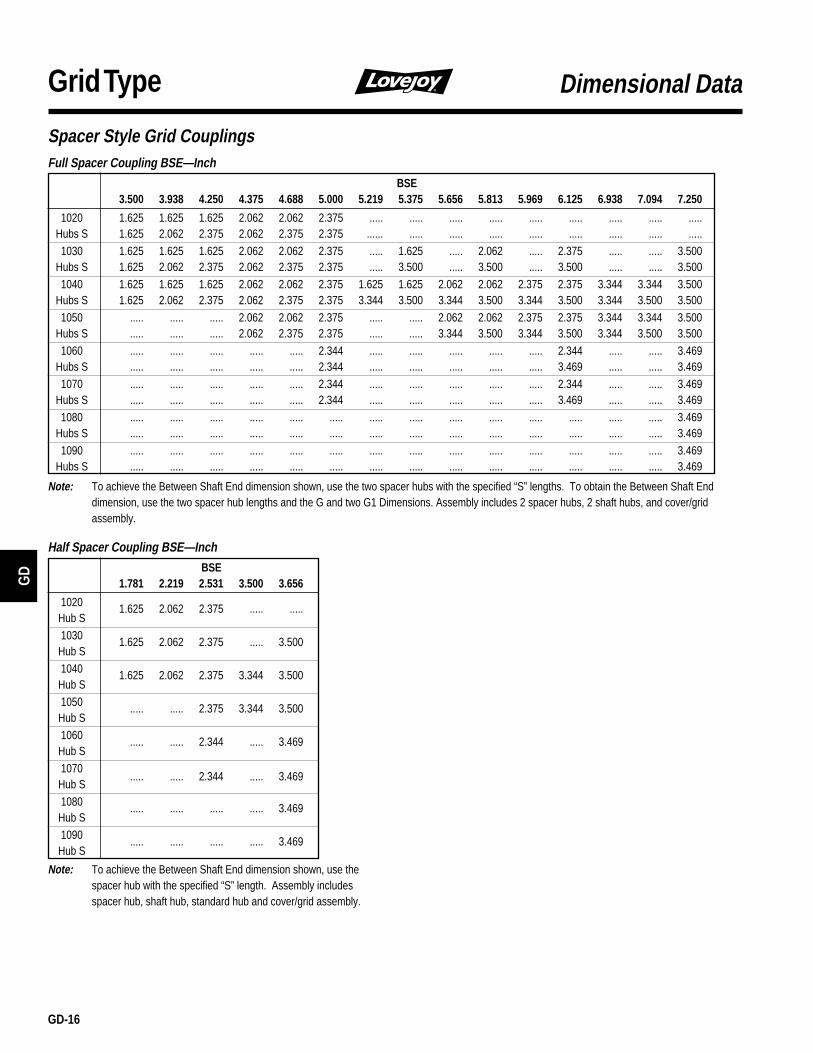
GD
GD-16
Grid Type
Full Spacer Coupling BSE—InchBSE
3.500 3.938 4.250 4.375 4.688 5.000 5.219 5.375 5.656 5.813 5.969 6.125 6.938 7.094 7.250
1020 1.625 1.625 1.625 2.062 2.062 2.375 ..... ..... ..... ..... ..... ..... ..... ..... .....Hubs S 1.625 2.062 2.375 2.062 2.375 2.375 ...... ..... ..... ..... ..... ..... ..... ..... .....1030 1.625 1.625 1.625 2.062 2.062 2.375 ..... 1.625 ..... 2.062 ..... 2.375 ..... ..... 3.500
Hubs S 1.625 2.062 2.375 2.062 2.375 2.375 ..... 3.500 ..... 3.500 ..... 3.500 ..... ..... 3.5001040 1.625 1.625 1.625 2.062 2.062 2.375 1.625 1.625 2.062 2.062 2.375 2.375 3.344 3.344 3.500
Hubs S 1.625 2.062 2.375 2.062 2.375 2.375 3.344 3.500 3.344 3.500 3.344 3.500 3.344 3.500 3.500
1050 ..... ..... ..... 2.062 2.062 2.375 ..... ..... 2.062 2.062 2.375 2.375 3.344 3.344 3.500Hubs S ..... ..... ..... 2.062 2.375 2.375 ..... ..... 3.344 3.500 3.344 3.500 3.344 3.500 3.5001060 ..... ..... ..... ..... ..... 2.344 ..... ..... ..... ..... ..... 2.344 ..... ..... 3.469
Hubs S ..... ..... ..... ..... ..... 2.344 ..... ..... ..... ..... ..... 3.469 ..... ..... 3.4691070 ..... ..... ..... ..... ..... 2.344 ..... ..... ..... ..... ..... 2.344 ..... ..... 3.469
Hubs S ..... ..... ..... ..... ..... 2.344 ..... ..... ..... ..... ..... 3.469 ..... ..... 3.469
1080 ..... ..... ..... ..... ..... ..... ..... ..... ..... ..... ..... ..... ..... ..... 3.469Hubs S ..... ..... ..... ..... ..... ..... ..... ..... ..... ..... ..... ..... ..... ..... 3.4691090 ..... ..... ..... ..... ..... ..... ..... ..... ..... ..... ..... ..... ..... ..... 3.469
Hubs S ..... ..... ..... ..... ..... ..... ..... ..... ..... ..... ..... ..... ..... ..... 3.469
Note: To achieve the Between Shaft End dimension shown, use the two spacer hubs with the specified “S” lengths. To obtain the Between Shaft Enddimension, use the two spacer hub lengths and the G and two G1 Dimensions. Assembly includes 2 spacer hubs, 2 shaft hubs, and cover/gridassembly.
Dimensional Data
Spacer Style Grid Couplings
Half Spacer Coupling BSE—InchBSE
1.781 2.219 2.531 3.500 3.656
1020 1.625 2.062 2.375 ..... .....Hub S1030 1.625 2.062 2.375 ..... 3.500
Hub S
1040 1.625 2.062 2.375 3.344 3.500Hub S1050 ..... ..... 2.375 3.344 3.500
Hub S1060 ..... ..... 2.344 ..... 3.469
Hub S
1070..... ..... 2.344 ..... 3.469
Hub S1080 ..... ..... ..... ..... 3.469
Hub S1090 ..... ..... ..... ..... 3.469
Hub S
Note: To achieve the Between Shaft End dimension shown, use thespacer hub with the specified “S” length. Assembly includesspacer hub, shaft hub, standard hub and cover/grid assembly.

GD-17
GD
Grid TypeLovejoy Coupling GreaseLovejoy Coupling Grease was designed to resist centrifugalseparation, thereby keeping the oil portion of the grease in theworking areas of the coupling. When using the Lovejoy CouplingGrease, lubrication intervals may be extended. A coupling exposedto extreme temperatures, excessive moisture, frequent reversals orgrease leakage may require more frequent lubrication.
The benefits of this product include:■ Highest pressure and wear protection available.■ Built-in rust and corrosion inhibitors.■ Increased coupling life.■ Reduced maintenance costs.■ Reduced downtime.■ Superior lubrication.
Lovejoy Coupling Grease has the U.S. Department of AgricultureFood Safety & Inspection Service approval for use in applicationswhere there is no possibility of contact with edible products.
SpecificationsThe specifications indicated below are average values, variationswhich do not affect product performance may occur.Temperature Operating Range:
-40°F (-40°C) to 250°F (121°C)Minimum Base Oil Viscosity:
2625SUS (567cSt) @ 100°F (38°C)Centrifuge Separation Characteristics:
ASTM D-4425-K36 = 0/24NLGI Grade: 1Minimum Dropping Point:
225°F (108°C)Minimum Timken Load: 40 lbs
If an alternative grease is used it should meet the minimumspecifications listed below. Table 4 is a list of grease products thatmeet the general specifications but should not be consideredexclusive recommendations.
Technical Data
WarrantyLovejoy, Inc. will replace any grid member which fails during the firstfive (5) years of normal use due to inadequate lubrication provided that:
■ The coupling was initially lubed with the proper amount of LovejoyCoupling Grease, as described in the Installation Instructions.
■ Recommended installation and operational alignment limitationsare observed.
■ Ambient temperatures are within -20° to +250°F (-29° to +121°C).
This guarantee of performance does not mean that a grid member willnever need to be replaced. The primary purpose of a coupling is to protectthe connected equipment by accommodating shaft misalignment and shockloads. In performing this function, some wear and fatiguing of metal mayoccur. However, if the grid member fails within the warranty period due tosome failure of the lubricant, Lovejoy will replace the grid member freeof charge.
Since 1927, Lovejoy couplings have saved thousands of companies bothtime and money by accommodating shaft misalignment, vibrations andshock loads, thus protecting connected equipment.
Now Lovejoy Grid Couplings join this long tradition. For this design, we haveidentified the best possible lubricants for couplings — those with highviscosity and low bleed rates. Lovejoy Coupling Grease meets these highexpectations — and yours.
A Lovejoy Grid coupling initially lubricated with Lovejoy Coupling Greasewill have the grid spring member warranted for 5 years against lubricationfailures and provide rugged, dependable service. It's our guarantee!
Benefits for your application are:■ Increased coupling life.■ Reduced maintenance cost.■ Reduced downtime.■ Superior lubrication.■ Significantly extended relubrication intervals.
Lovejoy Coupling Grease Limited 5-year Lubrication Warranty
Common Industrial Lubricants (NLGI Grade #2) Table 4Ambient Temperature Range:
0° F to 150° F -30° F to 100° F1
Manufacturer (-18° C to 66° C) (-34° C to 38° C)
Amoco Oil Co. Amolith Grease #2 Amolith Grease #2Atlantic Richfield Co. Litholene HEP 2 Litholene HEP 2Chevron U.S.A. Inc. Chevron Dura-Lith EP-2 Chevron Dura-Lith EP 2Cities Service Co. Citgo HEP-2 Citgo HEP 2Conoco Inc. EP Conolith #2 EP Conolith #2Exxon Company, USA Ronex MP Ronex MPGulf Oil Corp. Gulfcrown Grease #2 Gulfcrown Grease #2E.F. Houghton & Co. Cosmolube #2 Cosmolube #1Imperial Oil Ltd. Esso MP Grease H Lotemp EPKendall Refining Co. Kenlube L-421 Gease Kenlube L-427 GreaseKeystone Div. (Pennwalt) #81 Light #84 LightMobil Oil Corp. Mobilux EP 111 Mobilux #1Phillips Petroleum Co. IB & RB Grease Philube IB & RB GreaseShell Oil Co. Alvania Grease #2 Alvania Grease #2Standard Oil Co. (OH) Factran #2 Factran #2Sun Oil Company Prestige 42 Prestige 42Texaco Lubricants Starplex HD2 Multifak EP2Texaco Canada Inc. Marfak HD 2 Marfak APUnion Oil Co. (CA) Union Unoba #2 Union Unoba #2Valvoline Oil Co. Val-Lith EP #2 Val-Lith EP #2
Note: Check with lube manufacturer for approved lubricants to use in thefood processing industry.
Temperature Operating Range:0°F (-18°C) to 150°F (66°C)
Centrifuge Separation Characteristics:Low oil separation rate and high resistance toseparation from centrifuging.
NLGI Grade: 2Minimum Dropping Point: 190°F (74°C)