Embed Size (px)
Citation preview

Keysight Technologies Solutions for WLAN 80211ac Manufacturing Test
Application Note
Testing 80211ac Client and Infrastructure Devices Using a Fast Flexible and Cost-Effective Calibration and Non-Signaling Verification Solution
02 | Keysight | Solutions for WLAN 80211ac Manufacturing Test - Application Note
Overview
The number of wireless devices on the market these days is exploding and as a result so too has the number of usersmdashmany of whom now carry multiple wireless devices (eg cell phone laptop or tablet) More and more these devices are providing functionality beyond the ability to just make calls or surf the Internet That trend along with todayrsquos countless other media-rich applications is pushing current bandwidth availability to its limit and driving the need for wireless technologies capable of increasing bandwidth capacity
One such technology 80211ac promises to deliver the higher data rates necessary to meet consumers ever increasing data demands Unlike other standards being rolled out it achieves this relatively cheaply by leveraging the same 5-GHz technologies that are now well established with 80211n With the standardrsquos mandatory set of features a very high throughput of greater than 1 Gbps can be achieved When its optional features are implemented peak data rates up to 6 Gbps can be supported 80211ac achieves these data rates by building on 80211n with four key enhancements
ndash Wider channels 40- and 80-MHz channels are mandatory with optional support for a contiguous 160-MHz channel and non-contiguous 80+80-MHz channels
ndash Higher-order modulation 256QAM (optional) ndash Multiple Input Multiple Output (MIMO) support with up to 8
spatial streams and antennas although only 1 is mandatory ndash Support for multi-user MIMO to increase downlink
transmission efficiency
80211acrsquos ability to achieve such high data rates using these enhancements coupled with its cost-effectiveness are key reasons why it is expected to supplant 80211n in the coming years
Problem
Successfully building out the 80211ac ecosystem requires both client and infrastructure devices Fortunately producing these devices does not add any new types of tests As with other well established 80211 standard test plans manufacturers must test the transmitter for channel power spectral mask and Error Vector Magnitude (EVM)modulation accuracy or relative constellation error and the receiver for sensitivity and maximum input level MIMO testing may also be required MIMO processing is usually integrated into the chipset DSP but it remains depen-dent on the relative performance of each antennaamplifier chain and consequently needs to be well characterizedmdashat least by the chipset supplier during RampD
In addition to these standard tests 80211ac poses a number of new challenges in terms of modulation performance While 80211ac supports the BPSK QPSK 16QAM and 64QAM used in 80211n it also introduces 256QAM which can be used only in
the new wider 80-MHz or 160-MHz channels The 256QAM enables a faster data rate and better spectral efficiency in good link conditions but demands better receiver and transmitter performance to handle noise and interference Thatrsquos because the receiver needs to be able to differentiate between many more more tightly packed constellation points than for 16 or 64QAM Verifying the better EVM performance thatrsquos needed to support this higher-order modulation requires higher quality measurement equipment
Solution
With the number of 80211ac devices expected to reach the market by 2015 topping 500 million device manufacturers require a cost-effective and efficient solution for appropriately testing client and infrastructure devices Besides the transmitter and receiver testing which are similar to that required for 80211n 80211ac also introduces some new requirements wider RF bandwidth up to 160 MHz higher modulation up to 256QAM and higher order MIMO Consequently the solution must be able to support the new testing requirements It also must be flexible enough to support future changes to the 80211ac standard
One test solution that meets the criteria is the Keysight Technologies Incrsquos E6640A EXM Wireless Test Set which is designed for calibration and non-signaling verification of all cellular devices as well as WLAN through 80211ac The solution delivers the speed accuracy and port density needed to ramp up rapidly and optimize full-volume manufacturing while also being scalable to meet production needs It supports all of the new tests required for the 80211ac specification without the need for additional equipment
Achieving Faster Test with Sequence-Based Test Modes
The EXM enables both non-signaling and sequence-based testing as well as testing via Single Acquisition Multiple Measurement (SAMM) technology through its highly flexible sequencer capability (Figure 1) SAMM enables the EXM to make several measurements on the same captured device-under-test (DUT) data burst without having to make any major changes to chipset test modes With its sequencer capability the EXM can facilitate faster testing with current WiFi chipsets and their test modes while also allowing for future advances in chipset test modes
When using the EXM for 80211ac manufacturing test the DUT must first be set up to transmit a known pattern The EXM then has to be set up to capture that pattern and make the appropriate measurements To minimize test time the DUT and EXM may be set up simultaneously which injects a bit of parallelism into the process
03 | Keysight | Solutions for WLAN 80211ac Manufacturing Test - Application Note
Achieving Faster Test with Sequence-Based Test Modes (continued)
Several things are required to generate a powerful fast sequence The overall sequence as shown in Figure 2 is a combination of acquisitions (red bars) and measurement or analysis steps (blue bars) The engineer must be able to define what and when heshe wants to capture data and what measurements will be made Key to rapidly optimizing your testing is the ability to set up parameters quickly and easily compare measurements to real-world results and quickly make adjustments as needed
Acq 1 time
Sequence
Acquisition 1
Step 1 Step 2 Step 3 Step 4 Step 5 Step 6
Red = Acquisition vs Blue = Measurement Step
Acquisition 2
Step 1 Step 2 Step 3
EVM Power Spectral Mask EVM Power Power Power EVM Power Power PowerPower
Figure 1 The basic operation of the EXM solution in sequencer mode operation is shown here
Figure 2 Shown here is an example of the EXMrsquos WLAN sequencer
An EXM lsquosequencersquo can be comprised of up to hundreds of separate acquisitions (for each frequency and expected signal level trigger conditions are programmed) Figure 2 shows two such acquisitions Within each acquisition a number of lsquomeasurement stepsrsquo can be defined that will normally be programmed to match the programmed output from the DUT using its sequence mode Each measurement step can be set up to process and return one or more measurement results from the data acquired in that time period In the figure there are six measurement steps on the data from acquisition 1 The EXM se-quence is constructed to match the sequence programmed in the DUT and both are initiated together to capture the desired result
04 | Keysight | Solutions for WLAN 80211ac Manufacturing Test - Application Note
Throughput Optimization with Multi-Device Parallel Testing
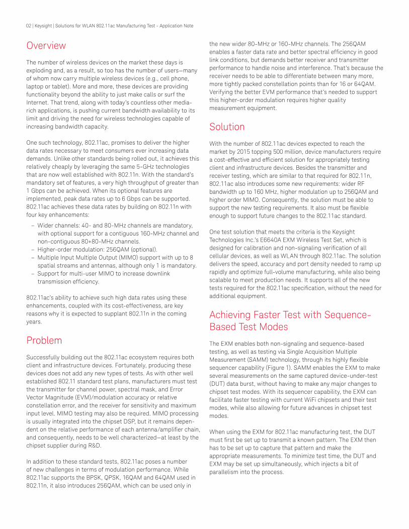
The EXM provides a high-density test capability by offering up to four complete test sets in a single 4U 19-inch rack package and is capable of 6-GHz frequency coverage and bandwidths up to 160 MHz Each test set comprises a Keysight X-Series vector signal generator (VSG) and vector signal analyzer (VSA) and includes a flexible 4-port RF InputOutput (IO) section that reduces the need and cost of complex external switching The internal VSG and VSA can each be switched to any of these four ports enabling connection of multiple devices with multiple antenna ports without the need for external switching In fact the EXM permits testing of up to 4 DUTs with fully asynchronous parallel testing as well as connection of up to 16 single-antenna 8 dual-antenna or 4 quadrant DUTs (Figures 3 and 4)
The EXM also natively supports ping-pong operationmdasha commonly deployed mode of operation for enhancing throughput efficiency (Figure 5) In ping-pong configuration while one device is being tested using the testerrsquos source and analyzer a second device is connected and remains ready to be switched onto the active test port as soon as the first device finishes testing This mode of operation eliminates the time it normally takes to connect and boot each device Moreover with the EXMrsquos built-in RFIO switching ports the process can be adopted without having to add external switching
Figure 3 As shown here the EXM permits the connection of up to 16 single-antenna DUTs
Figure 4 The EXM also allows users to connect 8 dual-antenna DUTs
Figure 5 In this example with a single antenna DUT DUT1 is shown connected to RFI|O3 and DUT 2 is shown connected to RFI|O4 port The sourceanalyzer is switched internally in sequence between the ports to which the different DUTs are attached
DUT1
time
Time saved
Tx -DUT1 Rx -DUT1 Boot Tx -DUT2 Rx -DUT2Boot
Sequential test for 2 DUTsDUT1 RFI|O3
Ping-Pong switch EXM connection between each DUT boot up DUT2 while DUT1 is being tested
Example for 2x single antenna DUT
Tx -DUT1 Rx -DUT1Boot
Boot Tx -DUT2 Rx -DUT2
DUT1 RFI|O3
DUT2 RFI|O4
DUT2
05 | Keysight | Solutions for WLAN 80211ac Manufacturing Test - Application Note
Improving Throughput Efficiency with Pipeline Operation
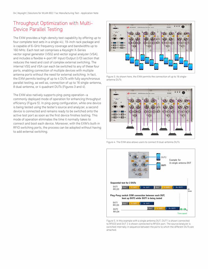
Pipeline operation describes a configuration whereby the transmitter of a 1st device is tested with the testerrsquos analyzer while the testerrsquos source is used to test the receiver of a 2nd device This approach is particularly well suited to WLAN testing which is a Time Division Duplex (TDD) system and is tested using control modes where only the Tx or the Rx is being tested Maximum throughput gain is achieved when the Tx test time equals the Rx test time for the Device Under Test (DUT) At this point the pipeline effectively halves the test time
With the E6640A the built-in RFIO switching ports enable pipeline operation to be adopted without additional external switching In Figure 6 DUT1 is shown connected to RFI|O3 and DUT 2 is connected to the RFI|O4 port This time the source and analyzer are switched internally between RFI|O3 and RFI|O4
Figure 6 In this example with a single antenna DUT DUT1 is shown connected to RFI|O3 and DUT 2 is shown connected to RFI|O4 port The transmitter of DUT1 is being tested with the testerrsquos analyzer The testerrsquos source is testing the receiver of DUT2
Test Coverage True MIMOSwitched
MIMOComposite
MIMO
Tx Test
Individual channel EVM
Combined EVM Individual channel power Total power (all channels) Tx Frequency error Channel cross powerisolation Channel response Individual Tx mask violationmargin Combined channel mask margin NA NA
RX Test
Individual RX channel PER (all channels active) Individual RX channel PER (one channel active) Combined RX channels PER RX Isolation
DUT Control
STBC offScrambling off
Select channel onoffTraining sequenceSpecial reference waveform
HWCost Multiple TRX Switch integrated into TRX External combiner
Speed Fastest Sequential stream capture
DUT control overhead
Table This table compares the three techniques that can be used for MIMO measurements in production The best test coverage is obtained using true MIMO but it comes at the cost of more test hardware as one TRX is required for each stream to be tested Switched MIMO is less costly but with the same test coverage Composite MIMO covers many parameters but cannot measure isolation between channels and requires DUT control commands to measure any individual channel metrics
MIMO Test
While 80211acrsquos support for MIMO technology is critical to enabling higher data rates its multiple antennas and data streams increase test complexity which in turn makes testing MIMO devices quite challenging Three techniques commonly used to verify MIMO performance include true MIMO switched MIMO and composite MIMO (see the Table) With true MIMO multiple analyzersource pairs are used to simultaneously test all MIMO channels while with switched MIMO a shared analyzersource pair is used to measure each channel in turn The composite MIMO technique calculates a limited set of MIMO metrics using a combined channel capture of a specially coded set of waveforms
To better deal with the complexity of MIMO the EXM supports up to 4x4 true MIMO and up to 3x3 switched MIMO In the case of true MIMO frequently used in RampD the EXM provides the multiple TRXs needed for simultaneous test of all MIMO channels Each antenna in the DUT is connected to a separate TRX in the tester (Figure 7) This method quickly provides engineers with a full and complete set of MIMO metrics since each channel is captured in parallel
06 | Keysight | Solutions for WLAN 80211ac Manufacturing Test - Application Note
MIMO Test (continued)
In contrast to true MIMO switched MIMO provides a much lower cost method for obtaining a full set of MIMO performance metrics using just a single EXM TRX With any STBC and scrambling turned off the EXMrsquos built-in fast switching RFIO corrects the DUT antennas in turn to the analyzer and captures data sequentially from successive signal bursts Keysight measurement software is then used to reconstruct the MIMO streams and perform measurements (Figure 8) The EXMrsquos quad-core processor maximizes production throughput by bringing the speed penalty associated with sequentially capturing data from the MIMO streams down to a minimum
Figure 7 In the diagram on the left the connection of the DUT for 4x4 true MIMO is shown
Figure 8 In the diagram on the left the connection of the DUT for 2x2 switched MIMO is shown In the example on the right the first frame from antenna 1 is captured followed by a later frame from antenna 2 The two streams are then reconstructed and each is processed using Keysightrsquos measurement software The software analyzes each stream in full returning individual results on power EVM and spectral mask plus a cross power measurement
07 | Keysight | Solutions for WLAN 80211ac Manufacturing Test - Application Note
Figure 9 In simplistic terms beamforming is a technique used to aim a signal directly at a target rather than broadcasting it to a wide area
Figure 10 The implicit feedback method assumes that the channel between the beamformer and beamformee is identical in the uplink and downlink directions Computation of correction matrices is required to eliminate any mismatch between the uplink and the downlink channels
Transmit Beamfoming
Beamforming is a technique in which the beamformer or transmitter used in beamforming utilizes the knowledge of the MIMO channel to generate a steering matrix that improves reception in the beamformee or the receiver in beamforming (Figure 9) It enables a dramatic improvement in WLAN 80211n and 80211ac performance in terms of reliability range and coverage
There are two categories of beamforming based on the methods of getting channel knowledge
ndash Category 1 Explicit Feedback Here the beamformee makes a direct estimate of the channel from training symbols sent from the beamformer to the beamformee
ndash Category 2 Implicit Feedback Here the beamformer receives long training symbols transmitted by the beamformee Implicit transmit beamforming is based on the assumption that the channel between the beamformer and beamformee is reciprocalThe beamformer obtains a reverse link channel estimate from a long training sequence in Acknowledgements (ACKs) and calculates the forward link HAB channel information as shown in Figure 10 It then applies channel compensation (and radio calibration) to the transmitted signal
For this to work the transmit chain radio performance needs to be calibrated to compensate for the transmit phase response Implicit transmit beamforming calibration testing can be easily performed using EXM Option V9077B-KFP or V9077B-KTP
A Wider Bandwidth Higher-Order Modulation Test Solution
The 80211ac standard specifies two ways to achieve the highest data rate a single 160-MHz contiguous channel (in many geographies only 2 or 3 such channels are available) or two non-contiguous 80-MHz channels (ie a 160-MHz non- contiguous channel) In the latter mode of operation a special spectral mask is defined Also note that the two 80-MHz channels used may have a number of different spacings
Figure 11 illustrates some key 80211ac transmitter measurements on a 160 MHz channel and 80+80 MHz channels The EXM covers all higher-order modulation tests using its 160 MHz maximum capture and demodulation bandwidth Channel power and modulation accuracy (EVM) measurements are required to be measured in up to a 160 MHz bandwidth The 160 MHz capture bandwidth also enables rapid spectral mask testing
Figure 11 A channel power measurement using the EXM
08 | Keysight | Solutions for WLAN 80211ac Manufacturing Test - Application Note
A Wider Bandwidth Higher-Order Modulation Test Solution (continued)
An adjusted spectral mask test is defined for the 80+80 MHz mode The test effectively combines the mask for two 80-MHz signals with a limit line of -25 dBr at the center point of the spectrum between the 80-MHz channels As an example Figure 12 shows two 80-MHz channels that are centered at 5210 and 5370 MHz respectively and are roughly 160 MHz apart The spectral mask test would therefore need to capture from 5090 to 5490 MHz a total span of 400 MHz (Figure 13)
In addition EXM can support measurements on 2x2 MIMO non-contiguous 80+80 MHz signals This advanced feature of 80211ac increases data rate with spatial multiplexing and spectrum efficient usage Figure 14 shows the constellation and EVM numerical results for 2 streams on 2 different frequency segments EXM can also help customers verify devices for SISO implementation of 80+80 MHz For more information on how to configure these measurements with the EXM contact Keysight directly The EXM can also be used to test 80211acrsquos 256QAM modulation (Figure 15) Since the constellation points are closer together in 256QAM better EVM performance is needed in the transmitter and receiver to correctly identify the intended point in the constellation The 80211ac standard has a transmitter relative constellation error or EVM specification of -32 dB for 256QAM compared to the -28 dB for 64QAM
As compared to previous generation test sets the EXM offers faster measurements increased ARB and analyzer capture memory increased number of sequencing steps and the enhanced sequencing capabilities needed to meet the challenges of the fast moving wireless device market In addition a high- performance quad-core controller ensures full performance even when the EXM is equipped with four complete test sets
5210 MHz 5370 MHz5090 MHz 54900 MHz5290 MHz
Figure 12 In this example two 80 MHz channels are shown 160 MHz apart
Figure 13 To conduct the 80211ac spectral mask test on the channels in Figure 6 data is captured from 5090 to 5490 MHz
Figure 15 An EVM 256 QAM measurement using the EXM
Figure 14 Shown here are the constellation and EVM numerical results for frequency segment 1 stream 1 frequency segment 1 stream 2 frequency segment 2 stream 1 and frequency segment 2 stream 2
09 | Keysight | Solutions for WLAN 80211ac Manufacturing Test - Application Note
Summary of Results
The emerging 80211ac standard offers the high-data throughput that todayrsquos consumers demand however it also creates a number of test challenges for 80211ac manufacturers producing client and infrastructure devices Luckily the EXM test set is well equipped to address all new 80211ac test requirements in the production process without the need for additional equipment Its flexibility and capabilities enable testing that is both fast and cost-effective providing a key differentiating factor for manufacturers working in the highly dynamic and competitive wireless device marketplace
For more information refer to the E6640A EXM wireless test set flyer configuration guide and data sheet at wwwkeysightcomfindE6640A Or download the application note Solutions for LTE-Advanced Manufacturing Test at wwwkeysightcomfindLTE-A
The Power to Accelerate Wireless Design and Test
Keysight is a leader in wireless test focused on the highest- performance design and test of wireless devices and networks with application-focused platforms optimized for existing and emerging standards Adding to this optimal RampD and field support Keysight allows engineers to better understand the intricacies of the continuously evolving wireless industry so you can accelerate your development of products
To learn more about Keysightrsquos suite of test and measurement products please visit wwwkeysightcomfindpowerofwireless
Related Applications
ndash WLAN ndash WLAN manufacturing test equipment ndash 80211ac manufacturing ndash Cellular manufacturing
Related Keysight Products
ndash Keysight EXM Wireless Test Set wwwkeysightcomfindexm
ndash Keysight N7625B Signal Studio Software wwwkeysightcomfindsignalstudio
10 | Keysight | Solutions for WLAN 80211ac Manufacturing Test - Application Note
This information is subject to change without noticecopy Keysight Technologies 2017Published in USA December 1 20175991-4113ENwwwkeysightcom
wwwkeysightcomfindpowerofwireless
For more information on Keysight Technologiesrsquo products applications or services please contact your local Keysight office The complete list is available atwwwkeysightcomfindcontactus
Americas Canada (877) 894 4414Brazil 55 11 3351 7010Mexico 001 800 254 2440United States (800) 829 4444
Asia PacificAustralia 1 800 629 485China 800 810 0189Hong Kong 800 938 693India 1 800 11 2626Japan 0120 (421) 345Korea 080 769 0800Malaysia 1 800 888 848Singapore 1 800 375 8100Taiwan 0800 047 866Other AP Countries (65) 6375 8100
Europe amp Middle EastAustria 0800 001122Belgium 0800 58580Finland 0800 523252France 0805 980333Germany 0800 6270999Ireland 1800 832700Israel 1 809 343051Italy 800 599100Luxembourg +32 800 58580Netherlands 0800 0233200Russia 8800 5009286Spain 800 000154Sweden 0200 882255Switzerland 0800 805353
Opt 1 (DE)Opt 2 (FR)Opt 3 (IT)
United Kingdom 0800 0260637
For other unlisted countrieswwwkeysightcomfindcontactus(BP-9-7-17)
DEKRA CertifiedISO9001 Quality Management System
wwwkeysightcomgoqualityKeysight Technologies IncDEKRA Certified ISO 90012015Quality Management System
Evolving Since 1939Our unique combination of hardware software services and people can help you reach your next breakthrough We are unlocking the future of technology From Hewlett-Packard to Agilent to Keysight
myKeysightwwwkeysightcomfindmykeysightA personalized view into the information most relevant to you
wwwkeysightcomfindemt_product_registrationRegister your products to get up-to-date product information and find warranty information
Keysight ServiceswwwkeysightcomfindserviceKeysight Services can help from acquisition to renewal across your instrumentrsquos lifecycle Our comprehensive service offeringsmdashone-stop calibration repair asset management technology refresh consulting training and moremdashhelps you improve product quality and lower costs
Keysight Assurance PlanswwwkeysightcomfindAssurancePlansUp to ten years of protection and no budgetary surprises to ensure your instruments are operating to specification so you can rely on accurate measurements
Keysight Channel PartnerswwwkeysightcomfindchannelpartnersGet the best of both worlds Keysightrsquos measurement expertise and product breadth combined with channel partner convenience
02 | Keysight | Solutions for WLAN 80211ac Manufacturing Test - Application Note
Overview
The number of wireless devices on the market these days is exploding and as a result so too has the number of usersmdashmany of whom now carry multiple wireless devices (eg cell phone laptop or tablet) More and more these devices are providing functionality beyond the ability to just make calls or surf the Internet That trend along with todayrsquos countless other media-rich applications is pushing current bandwidth availability to its limit and driving the need for wireless technologies capable of increasing bandwidth capacity
One such technology 80211ac promises to deliver the higher data rates necessary to meet consumers ever increasing data demands Unlike other standards being rolled out it achieves this relatively cheaply by leveraging the same 5-GHz technologies that are now well established with 80211n With the standardrsquos mandatory set of features a very high throughput of greater than 1 Gbps can be achieved When its optional features are implemented peak data rates up to 6 Gbps can be supported 80211ac achieves these data rates by building on 80211n with four key enhancements
ndash Wider channels 40- and 80-MHz channels are mandatory with optional support for a contiguous 160-MHz channel and non-contiguous 80+80-MHz channels
ndash Higher-order modulation 256QAM (optional) ndash Multiple Input Multiple Output (MIMO) support with up to 8
spatial streams and antennas although only 1 is mandatory ndash Support for multi-user MIMO to increase downlink
transmission efficiency
80211acrsquos ability to achieve such high data rates using these enhancements coupled with its cost-effectiveness are key reasons why it is expected to supplant 80211n in the coming years
Problem
Successfully building out the 80211ac ecosystem requires both client and infrastructure devices Fortunately producing these devices does not add any new types of tests As with other well established 80211 standard test plans manufacturers must test the transmitter for channel power spectral mask and Error Vector Magnitude (EVM)modulation accuracy or relative constellation error and the receiver for sensitivity and maximum input level MIMO testing may also be required MIMO processing is usually integrated into the chipset DSP but it remains depen-dent on the relative performance of each antennaamplifier chain and consequently needs to be well characterizedmdashat least by the chipset supplier during RampD
In addition to these standard tests 80211ac poses a number of new challenges in terms of modulation performance While 80211ac supports the BPSK QPSK 16QAM and 64QAM used in 80211n it also introduces 256QAM which can be used only in
the new wider 80-MHz or 160-MHz channels The 256QAM enables a faster data rate and better spectral efficiency in good link conditions but demands better receiver and transmitter performance to handle noise and interference Thatrsquos because the receiver needs to be able to differentiate between many more more tightly packed constellation points than for 16 or 64QAM Verifying the better EVM performance thatrsquos needed to support this higher-order modulation requires higher quality measurement equipment
Solution
With the number of 80211ac devices expected to reach the market by 2015 topping 500 million device manufacturers require a cost-effective and efficient solution for appropriately testing client and infrastructure devices Besides the transmitter and receiver testing which are similar to that required for 80211n 80211ac also introduces some new requirements wider RF bandwidth up to 160 MHz higher modulation up to 256QAM and higher order MIMO Consequently the solution must be able to support the new testing requirements It also must be flexible enough to support future changes to the 80211ac standard
One test solution that meets the criteria is the Keysight Technologies Incrsquos E6640A EXM Wireless Test Set which is designed for calibration and non-signaling verification of all cellular devices as well as WLAN through 80211ac The solution delivers the speed accuracy and port density needed to ramp up rapidly and optimize full-volume manufacturing while also being scalable to meet production needs It supports all of the new tests required for the 80211ac specification without the need for additional equipment
Achieving Faster Test with Sequence-Based Test Modes
The EXM enables both non-signaling and sequence-based testing as well as testing via Single Acquisition Multiple Measurement (SAMM) technology through its highly flexible sequencer capability (Figure 1) SAMM enables the EXM to make several measurements on the same captured device-under-test (DUT) data burst without having to make any major changes to chipset test modes With its sequencer capability the EXM can facilitate faster testing with current WiFi chipsets and their test modes while also allowing for future advances in chipset test modes
When using the EXM for 80211ac manufacturing test the DUT must first be set up to transmit a known pattern The EXM then has to be set up to capture that pattern and make the appropriate measurements To minimize test time the DUT and EXM may be set up simultaneously which injects a bit of parallelism into the process
03 | Keysight | Solutions for WLAN 80211ac Manufacturing Test - Application Note
Achieving Faster Test with Sequence-Based Test Modes (continued)
Several things are required to generate a powerful fast sequence The overall sequence as shown in Figure 2 is a combination of acquisitions (red bars) and measurement or analysis steps (blue bars) The engineer must be able to define what and when heshe wants to capture data and what measurements will be made Key to rapidly optimizing your testing is the ability to set up parameters quickly and easily compare measurements to real-world results and quickly make adjustments as needed
Acq 1 time
Sequence
Acquisition 1
Step 1 Step 2 Step 3 Step 4 Step 5 Step 6
Red = Acquisition vs Blue = Measurement Step
Acquisition 2
Step 1 Step 2 Step 3
EVM Power Spectral Mask EVM Power Power Power EVM Power Power PowerPower
Figure 1 The basic operation of the EXM solution in sequencer mode operation is shown here
Figure 2 Shown here is an example of the EXMrsquos WLAN sequencer
An EXM lsquosequencersquo can be comprised of up to hundreds of separate acquisitions (for each frequency and expected signal level trigger conditions are programmed) Figure 2 shows two such acquisitions Within each acquisition a number of lsquomeasurement stepsrsquo can be defined that will normally be programmed to match the programmed output from the DUT using its sequence mode Each measurement step can be set up to process and return one or more measurement results from the data acquired in that time period In the figure there are six measurement steps on the data from acquisition 1 The EXM se-quence is constructed to match the sequence programmed in the DUT and both are initiated together to capture the desired result
04 | Keysight | Solutions for WLAN 80211ac Manufacturing Test - Application Note
Throughput Optimization with Multi-Device Parallel Testing
The EXM provides a high-density test capability by offering up to four complete test sets in a single 4U 19-inch rack package and is capable of 6-GHz frequency coverage and bandwidths up to 160 MHz Each test set comprises a Keysight X-Series vector signal generator (VSG) and vector signal analyzer (VSA) and includes a flexible 4-port RF InputOutput (IO) section that reduces the need and cost of complex external switching The internal VSG and VSA can each be switched to any of these four ports enabling connection of multiple devices with multiple antenna ports without the need for external switching In fact the EXM permits testing of up to 4 DUTs with fully asynchronous parallel testing as well as connection of up to 16 single-antenna 8 dual-antenna or 4 quadrant DUTs (Figures 3 and 4)
The EXM also natively supports ping-pong operationmdasha commonly deployed mode of operation for enhancing throughput efficiency (Figure 5) In ping-pong configuration while one device is being tested using the testerrsquos source and analyzer a second device is connected and remains ready to be switched onto the active test port as soon as the first device finishes testing This mode of operation eliminates the time it normally takes to connect and boot each device Moreover with the EXMrsquos built-in RFIO switching ports the process can be adopted without having to add external switching
Figure 3 As shown here the EXM permits the connection of up to 16 single-antenna DUTs
Figure 4 The EXM also allows users to connect 8 dual-antenna DUTs
Figure 5 In this example with a single antenna DUT DUT1 is shown connected to RFI|O3 and DUT 2 is shown connected to RFI|O4 port The sourceanalyzer is switched internally in sequence between the ports to which the different DUTs are attached
DUT1
time
Time saved
Tx -DUT1 Rx -DUT1 Boot Tx -DUT2 Rx -DUT2Boot
Sequential test for 2 DUTsDUT1 RFI|O3
Ping-Pong switch EXM connection between each DUT boot up DUT2 while DUT1 is being tested
Example for 2x single antenna DUT
Tx -DUT1 Rx -DUT1Boot
Boot Tx -DUT2 Rx -DUT2
DUT1 RFI|O3
DUT2 RFI|O4
DUT2
05 | Keysight | Solutions for WLAN 80211ac Manufacturing Test - Application Note
Improving Throughput Efficiency with Pipeline Operation
Pipeline operation describes a configuration whereby the transmitter of a 1st device is tested with the testerrsquos analyzer while the testerrsquos source is used to test the receiver of a 2nd device This approach is particularly well suited to WLAN testing which is a Time Division Duplex (TDD) system and is tested using control modes where only the Tx or the Rx is being tested Maximum throughput gain is achieved when the Tx test time equals the Rx test time for the Device Under Test (DUT) At this point the pipeline effectively halves the test time
With the E6640A the built-in RFIO switching ports enable pipeline operation to be adopted without additional external switching In Figure 6 DUT1 is shown connected to RFI|O3 and DUT 2 is connected to the RFI|O4 port This time the source and analyzer are switched internally between RFI|O3 and RFI|O4
Figure 6 In this example with a single antenna DUT DUT1 is shown connected to RFI|O3 and DUT 2 is shown connected to RFI|O4 port The transmitter of DUT1 is being tested with the testerrsquos analyzer The testerrsquos source is testing the receiver of DUT2
Test Coverage True MIMOSwitched
MIMOComposite
MIMO
Tx Test
Individual channel EVM
Combined EVM Individual channel power Total power (all channels) Tx Frequency error Channel cross powerisolation Channel response Individual Tx mask violationmargin Combined channel mask margin NA NA
RX Test
Individual RX channel PER (all channels active) Individual RX channel PER (one channel active) Combined RX channels PER RX Isolation
DUT Control
STBC offScrambling off
Select channel onoffTraining sequenceSpecial reference waveform
HWCost Multiple TRX Switch integrated into TRX External combiner
Speed Fastest Sequential stream capture
DUT control overhead
Table This table compares the three techniques that can be used for MIMO measurements in production The best test coverage is obtained using true MIMO but it comes at the cost of more test hardware as one TRX is required for each stream to be tested Switched MIMO is less costly but with the same test coverage Composite MIMO covers many parameters but cannot measure isolation between channels and requires DUT control commands to measure any individual channel metrics
MIMO Test
While 80211acrsquos support for MIMO technology is critical to enabling higher data rates its multiple antennas and data streams increase test complexity which in turn makes testing MIMO devices quite challenging Three techniques commonly used to verify MIMO performance include true MIMO switched MIMO and composite MIMO (see the Table) With true MIMO multiple analyzersource pairs are used to simultaneously test all MIMO channels while with switched MIMO a shared analyzersource pair is used to measure each channel in turn The composite MIMO technique calculates a limited set of MIMO metrics using a combined channel capture of a specially coded set of waveforms
To better deal with the complexity of MIMO the EXM supports up to 4x4 true MIMO and up to 3x3 switched MIMO In the case of true MIMO frequently used in RampD the EXM provides the multiple TRXs needed for simultaneous test of all MIMO channels Each antenna in the DUT is connected to a separate TRX in the tester (Figure 7) This method quickly provides engineers with a full and complete set of MIMO metrics since each channel is captured in parallel
06 | Keysight | Solutions for WLAN 80211ac Manufacturing Test - Application Note
MIMO Test (continued)
In contrast to true MIMO switched MIMO provides a much lower cost method for obtaining a full set of MIMO performance metrics using just a single EXM TRX With any STBC and scrambling turned off the EXMrsquos built-in fast switching RFIO corrects the DUT antennas in turn to the analyzer and captures data sequentially from successive signal bursts Keysight measurement software is then used to reconstruct the MIMO streams and perform measurements (Figure 8) The EXMrsquos quad-core processor maximizes production throughput by bringing the speed penalty associated with sequentially capturing data from the MIMO streams down to a minimum
Figure 7 In the diagram on the left the connection of the DUT for 4x4 true MIMO is shown
Figure 8 In the diagram on the left the connection of the DUT for 2x2 switched MIMO is shown In the example on the right the first frame from antenna 1 is captured followed by a later frame from antenna 2 The two streams are then reconstructed and each is processed using Keysightrsquos measurement software The software analyzes each stream in full returning individual results on power EVM and spectral mask plus a cross power measurement
07 | Keysight | Solutions for WLAN 80211ac Manufacturing Test - Application Note
Figure 9 In simplistic terms beamforming is a technique used to aim a signal directly at a target rather than broadcasting it to a wide area
Figure 10 The implicit feedback method assumes that the channel between the beamformer and beamformee is identical in the uplink and downlink directions Computation of correction matrices is required to eliminate any mismatch between the uplink and the downlink channels
Transmit Beamfoming
Beamforming is a technique in which the beamformer or transmitter used in beamforming utilizes the knowledge of the MIMO channel to generate a steering matrix that improves reception in the beamformee or the receiver in beamforming (Figure 9) It enables a dramatic improvement in WLAN 80211n and 80211ac performance in terms of reliability range and coverage
There are two categories of beamforming based on the methods of getting channel knowledge
ndash Category 1 Explicit Feedback Here the beamformee makes a direct estimate of the channel from training symbols sent from the beamformer to the beamformee
ndash Category 2 Implicit Feedback Here the beamformer receives long training symbols transmitted by the beamformee Implicit transmit beamforming is based on the assumption that the channel between the beamformer and beamformee is reciprocalThe beamformer obtains a reverse link channel estimate from a long training sequence in Acknowledgements (ACKs) and calculates the forward link HAB channel information as shown in Figure 10 It then applies channel compensation (and radio calibration) to the transmitted signal
For this to work the transmit chain radio performance needs to be calibrated to compensate for the transmit phase response Implicit transmit beamforming calibration testing can be easily performed using EXM Option V9077B-KFP or V9077B-KTP
A Wider Bandwidth Higher-Order Modulation Test Solution
The 80211ac standard specifies two ways to achieve the highest data rate a single 160-MHz contiguous channel (in many geographies only 2 or 3 such channels are available) or two non-contiguous 80-MHz channels (ie a 160-MHz non- contiguous channel) In the latter mode of operation a special spectral mask is defined Also note that the two 80-MHz channels used may have a number of different spacings
Figure 11 illustrates some key 80211ac transmitter measurements on a 160 MHz channel and 80+80 MHz channels The EXM covers all higher-order modulation tests using its 160 MHz maximum capture and demodulation bandwidth Channel power and modulation accuracy (EVM) measurements are required to be measured in up to a 160 MHz bandwidth The 160 MHz capture bandwidth also enables rapid spectral mask testing
Figure 11 A channel power measurement using the EXM
08 | Keysight | Solutions for WLAN 80211ac Manufacturing Test - Application Note
A Wider Bandwidth Higher-Order Modulation Test Solution (continued)
An adjusted spectral mask test is defined for the 80+80 MHz mode The test effectively combines the mask for two 80-MHz signals with a limit line of -25 dBr at the center point of the spectrum between the 80-MHz channels As an example Figure 12 shows two 80-MHz channels that are centered at 5210 and 5370 MHz respectively and are roughly 160 MHz apart The spectral mask test would therefore need to capture from 5090 to 5490 MHz a total span of 400 MHz (Figure 13)
In addition EXM can support measurements on 2x2 MIMO non-contiguous 80+80 MHz signals This advanced feature of 80211ac increases data rate with spatial multiplexing and spectrum efficient usage Figure 14 shows the constellation and EVM numerical results for 2 streams on 2 different frequency segments EXM can also help customers verify devices for SISO implementation of 80+80 MHz For more information on how to configure these measurements with the EXM contact Keysight directly The EXM can also be used to test 80211acrsquos 256QAM modulation (Figure 15) Since the constellation points are closer together in 256QAM better EVM performance is needed in the transmitter and receiver to correctly identify the intended point in the constellation The 80211ac standard has a transmitter relative constellation error or EVM specification of -32 dB for 256QAM compared to the -28 dB for 64QAM
As compared to previous generation test sets the EXM offers faster measurements increased ARB and analyzer capture memory increased number of sequencing steps and the enhanced sequencing capabilities needed to meet the challenges of the fast moving wireless device market In addition a high- performance quad-core controller ensures full performance even when the EXM is equipped with four complete test sets
5210 MHz 5370 MHz5090 MHz 54900 MHz5290 MHz
Figure 12 In this example two 80 MHz channels are shown 160 MHz apart
Figure 13 To conduct the 80211ac spectral mask test on the channels in Figure 6 data is captured from 5090 to 5490 MHz
Figure 15 An EVM 256 QAM measurement using the EXM
Figure 14 Shown here are the constellation and EVM numerical results for frequency segment 1 stream 1 frequency segment 1 stream 2 frequency segment 2 stream 1 and frequency segment 2 stream 2
09 | Keysight | Solutions for WLAN 80211ac Manufacturing Test - Application Note
Summary of Results
The emerging 80211ac standard offers the high-data throughput that todayrsquos consumers demand however it also creates a number of test challenges for 80211ac manufacturers producing client and infrastructure devices Luckily the EXM test set is well equipped to address all new 80211ac test requirements in the production process without the need for additional equipment Its flexibility and capabilities enable testing that is both fast and cost-effective providing a key differentiating factor for manufacturers working in the highly dynamic and competitive wireless device marketplace
For more information refer to the E6640A EXM wireless test set flyer configuration guide and data sheet at wwwkeysightcomfindE6640A Or download the application note Solutions for LTE-Advanced Manufacturing Test at wwwkeysightcomfindLTE-A
The Power to Accelerate Wireless Design and Test
Keysight is a leader in wireless test focused on the highest- performance design and test of wireless devices and networks with application-focused platforms optimized for existing and emerging standards Adding to this optimal RampD and field support Keysight allows engineers to better understand the intricacies of the continuously evolving wireless industry so you can accelerate your development of products
To learn more about Keysightrsquos suite of test and measurement products please visit wwwkeysightcomfindpowerofwireless
Related Applications
ndash WLAN ndash WLAN manufacturing test equipment ndash 80211ac manufacturing ndash Cellular manufacturing
Related Keysight Products
ndash Keysight EXM Wireless Test Set wwwkeysightcomfindexm
ndash Keysight N7625B Signal Studio Software wwwkeysightcomfindsignalstudio
10 | Keysight | Solutions for WLAN 80211ac Manufacturing Test - Application Note
This information is subject to change without noticecopy Keysight Technologies 2017Published in USA December 1 20175991-4113ENwwwkeysightcom
wwwkeysightcomfindpowerofwireless
For more information on Keysight Technologiesrsquo products applications or services please contact your local Keysight office The complete list is available atwwwkeysightcomfindcontactus
Americas Canada (877) 894 4414Brazil 55 11 3351 7010Mexico 001 800 254 2440United States (800) 829 4444
Asia PacificAustralia 1 800 629 485China 800 810 0189Hong Kong 800 938 693India 1 800 11 2626Japan 0120 (421) 345Korea 080 769 0800Malaysia 1 800 888 848Singapore 1 800 375 8100Taiwan 0800 047 866Other AP Countries (65) 6375 8100
Europe amp Middle EastAustria 0800 001122Belgium 0800 58580Finland 0800 523252France 0805 980333Germany 0800 6270999Ireland 1800 832700Israel 1 809 343051Italy 800 599100Luxembourg +32 800 58580Netherlands 0800 0233200Russia 8800 5009286Spain 800 000154Sweden 0200 882255Switzerland 0800 805353
Opt 1 (DE)Opt 2 (FR)Opt 3 (IT)
United Kingdom 0800 0260637
For other unlisted countrieswwwkeysightcomfindcontactus(BP-9-7-17)
DEKRA CertifiedISO9001 Quality Management System
wwwkeysightcomgoqualityKeysight Technologies IncDEKRA Certified ISO 90012015Quality Management System
Evolving Since 1939Our unique combination of hardware software services and people can help you reach your next breakthrough We are unlocking the future of technology From Hewlett-Packard to Agilent to Keysight
myKeysightwwwkeysightcomfindmykeysightA personalized view into the information most relevant to you
wwwkeysightcomfindemt_product_registrationRegister your products to get up-to-date product information and find warranty information
Keysight ServiceswwwkeysightcomfindserviceKeysight Services can help from acquisition to renewal across your instrumentrsquos lifecycle Our comprehensive service offeringsmdashone-stop calibration repair asset management technology refresh consulting training and moremdashhelps you improve product quality and lower costs
Keysight Assurance PlanswwwkeysightcomfindAssurancePlansUp to ten years of protection and no budgetary surprises to ensure your instruments are operating to specification so you can rely on accurate measurements
Keysight Channel PartnerswwwkeysightcomfindchannelpartnersGet the best of both worlds Keysightrsquos measurement expertise and product breadth combined with channel partner convenience
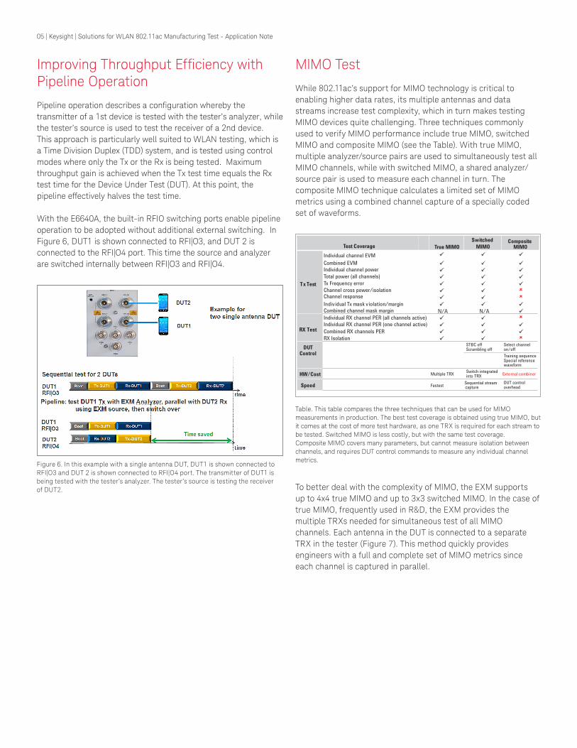