Embed Size (px)
Citation preview

Keysight Technologies Ininiium Z-Series OscilloscopesData Sheet
Achieve new extremes – 63 GHz of real-time bandwidth on 2 channels – 33 GHz of real-time bandwidth on 4 channels

02 | Keysight | Ininiium Z-Series Oscilloscopes - Data Sheet
Achieve new extremes
With the emergence of tech-nologies pushing hundreds of Gb/s, an oscilloscope must now have high bandwidth, low noise and fast processing. That is the idea behind the Z-Series. It features up to 63 GHz of real-time oscil-loscope bandwidth and the industry’s leading noise and jitter measurement loors.
Featuring – 63 GHz of real-time oscilloscope
bandwidth – The industry’s highest 4-channel
bandwidth in a single frame
(33 GHz)
– The industry’s lowest noise and jitter measurement loor
– The industry’s deepest memory (up to 2 Gpts)
Bandwidth Sample rate Memory depth
2 Channel 4 channel 2 channel 4 channel Standard Maximum
DSAZ634A63 GHz 33 GHz
160 GS/s 80 GS/s
100M 2 Gpts
DSOZ634A 50M 2 Gpts
DSAZ594A59 GHz 33 GHz
100M 2 Gpts
DSOZ594A 50M 2 Gpts
DSAZ504A50 GHz 33 GHz
100M 2 Gpts
DSOZ504A 50M 2 Gpts
DSAZ334A33 GHz 33 GHz
80 GS/s 80 GS/s
100M 2 Gpts
DSOZ334A 50M 2 Gpts
DSAZ254A25 GHz 25 GHz
100M 2 Gpts
DSOZ254A 50M 2 Gpts
DSAZ204A20 GHz 20 GHz
100M 2 Gpts
DSOZ204A 50M 2 Gpts
The Ininiium Z-Series captures rise times as fast as 5 ps (20/80).

03 | Keysight | Ininiium Z-Series Oscilloscopes - Data Sheet
Advanced IC design and technology help you solve your biggest problemsAt the extremes of electrical and optical measurements …
You need to make rise time measurements without being limited by scope bandwidthThe Z-Series is the Keysight
Technologies, Inc. second generation
of enabling 63 GHz of oscilloscope
bandwidth. RealEdge technology is
implemented using a unique combi-
nation of time interleaving, frequency
interleaving and proprietary signal
processing.
You need to see your signal and not oscilloscope noiseThe Z-Series leverages technology from
the award-winning Infiniium 90000
X- and 90000 Q-Series oscilloscopes,
which provide leading signal integrity
specifications. The Z-Series takes
advantage of leading-edge indium
phosphide chip technology and custom
thin film packaging technology, which
ultimately leads to the lowest-noise
real-time oscilloscope in the world. With
industry-leading bandwidths, Z-Series
scopes let you see your fastest signals
as they really are.
You need fast analysis and hardware acceleration The Z-Series has a capacitive touch
screen, new processor and 16 G of
RAM to ensure faster processing than
previous-generation Infiniium oscillo-
scopes.
Ininiium’s custom multichip modules feature indium phosphide chips and Keysight proprietary packaging technology, enabling high bandwidth and low noise.
RealEdge technology blocks enable 63-GHz real-time bandwidth.
The Z-Series features the industry’s lowest noise loor.

04 | Keysight | Ininiium Z-Series Oscilloscopes - Data Sheet
With 63 GHz of bandwidth to capture rise
times as fast as 5 ps and recover clocks
on NRZ data rates as fast as 120 Gbit/s,
the Z-Series is the world’s fastest real-time
oscilloscope. Its four channels at 33 GHz
make it ideal for 32 Gbit/s and greater
SERDES designs. In addition to providing
leading edge bandwidth, the Z-Series helps
you to find your real edge, by featuring
the industry’s lowest noise and jitter mea-
surement floor, which means less scope
noise in your measurements and a truer
depiction of your signal.
Z-Series features the following to enable extreme digital analysis1. Full offline analysis
2. Flexible user interface that supports
multiple displays and multi-touch (aka
gestures)
3. Two unique jitter separation algorithms,
including bounded uncorrelated jitter
breakdown
4. Clock recovery on NRZ data rates as fast
as 120 Gb/s
5. Memory depth that captures
milliseconds of data at 160 GSa/s
Capture, display and measure multiple real-time eyes simultaneously with the Z-Series.
With its lat frequency response and low noise, the Z-Series is able to accurately measure jitter compo-nents such as ISI.
The Oscilloscope - Digital measurement and analysis

05 | Keysight | Ininiium Z-Series Oscilloscopes - Data Sheet
You need to easily compute both magnitude and phaseInfiniium Z-Series oscilloscopes include a
Fast Fourier Transform (FFT) for frequency
domain (spectrum) analysis. The integrated
FFT offers an alternative to a dedicated
spectrum analyzer. Use the FFT to compute
both magnitude and phase and take advan-
tage of several useful features to assist
in spectral analysis. The FFT can control
span and resolution bandwidth. Automatic
measurements and markers measure
spectral peak frequencies and magnitudes
as well as deltas between peaks. Use the
amplitude demodulation (envelope mode)
to measure rise and fall times on the entire
envelope.
Z-Series features the following to enable extreme RealEdge analysis
– Multiple FFT windows including Han-ning, rectangular, Blackman-Harris, lattop, and Hamming
– Peak search and navigation for fast analysis
– Amplitude modulation (envelope mode) - create radar envelopes
– FFT mask trigger – Gated FFT measurements
The Z-Series FFT quickly identiies peaks and has key controls such as span, start, stop, etc. that make the oscilloscope behave more like a spectrum analyzer.
Use the FFT mask to test frequency margins and capture rare events.
Ampltitude demodulation makes it possible to analyze dificult waveforms such as envelopes.
The spectrum analyzer - Radar and satellite communications analysis

06 | Keysight | Ininiium Z-Series Oscilloscopes - Data Sheet
The optical modulation analyzer
Z-Series oscilloscopes are also
available in combination with the N4391A
optical modulation analyzer as a fully
specified turn-key instrument. This
compact solution offers the highest
bandwidth available on the market and
is the most advanced test solution for
advanced research on 400-G and terabit
transmission. Even for the lower 20-GHz
bandwidth range, this compact and easy-
to-use solution is a reference system for
100-G transmission required by R&D labs
working at 100 G and beyond. By providing
four channels of 33 GHz bandwidth, the
Z-Series saves you the expense of a
second instrument to analyze dual polar-
ization.
If you prefer to operate with your own
optical receivers but want to benefit from
the enormous analysis capability, you can
get the N4391A’s analysis software as a
standalone package.
Features and beneits – Up to 33 GHz true analog bandwidth
on four channels – 40 GHz support to the N4391A in near
future – Up to 120 Gbaud symbol rate analysis – Four times better EVM noise loor than
typical QPSK transmitter – Compact four channels in turn-key
solution – 4 x 80-Gs real-time sampling for opti-
mal phase tracking – Well-deined interface to include your
own MATLAB algorithms – Customer-conigurable APSK and
OFDM decoders
The N4391A offers a powerful toolset to debug the most challenging errors,with tools proven by thousands of RF engineers

07 | Keysight | Ininiium Z-Series Oscilloscopes - Data Sheet
You need to be able to maximize your margins by removing the effects of cables and ixturesAs bandwidths continue to increase and
cable loss becomes more and more of a
problem, the Z-Series has the technology
to solve this issue. The Z-Series oscillo-
scopes offer award-winning PrecisionProbe
Advanced technology. You no longer need
to ignore cable loss because you are short
on time or budget. Using PrecisionProbe
Advanced technology, you can characterize
cables as fast as 63 GHz and remove
the loss that they create. PrecisionProbe
Advanced technology gives you one of the
world’s fastest edges at less than
5 ps and uses this edge to perform a TDT
on your cable. Based on the loss of your
cable, PrecisionProbe Advanced then
compensates your measurement system,
gaining back valuable margin typically lost
in cables.
You need to automate multiple lanes automatically and still maximize marginsThe Z-Series features many compliance
applications, which provide full automation
of any switch connected to your system.
The software is fully compatible with
PrecisionProbe Advanced compensation,
which allows you to characterize every
input using only your Z-Series oscilloscope
and then seamlessly automate every
measurement in your compliance applica-
tion. Save valuable time and resources in
such technologies as DisplayPort and PCI
Express® gen3.
By analyzing cables you can increase your margins by removing insertion loss caused by cables.
The network analyzer - Time-Domain Transmission (TDT)

08 | Keysight | Ininiium Z-Series Oscilloscopes - Data Sheet
The world’s fastest probing system for your highest performance needs
The InfiniiMax III probing system provides the highest bandwidth and incredibly
low loading to allow for a completely new level of signal fidelity and accuracy. Four
different InfiniiMax III probe amplifiers ranging from 16 to 30 GHz are available for
matching your probing solution to your performance and budget requirements. The
InfiniiMax III probe system is unmatched by any product in the market. It uses a
proprietary 200-GHz fT indium phosphide IC process with backside ground vias and
novel thick-film technology to accommodate your highest-performance needs.
Description Probe or accessory Bandwidth
30-GHz InfiniiMax III probe amp N2803A 30 GHz
25-GHz InfiniiMax III probe amp N2802A 25 GHz
20-GHz InfiniiMax III probe amp N2801A 20 GHz
16-GHz InfiniiMax III probe amp N2800A 16 GHz
ZIF probe head N5439A 28 GHz
Browser (handheld) probe head N5445A 30 GHz
Solder-in probe head N5441A 16 GHz
PC board ZIF tip N2838A 25 GHz
3.5/2.92/SMA probe head N5444A 28 GHz
Performance verification fixture N5443A 30 GHz
Solder-in head N2836A 26 GHz
450-ohm ZIF tip kit (set of five) N5440A 28 GHz
200-ohm ZIF tip kit (set of five) N5447A 28 GHz
Browser tip replacement N5476A 30 GHz
Precision BNC adaptor N5442A 13 GHz
Sampling scope adaptor N5477A 30 GHz
2.9-mm flexible cable N5448A 30 GHz
High-impedance probe adaptor N5449A 500 MHz
35-GHz flexible cable N2812A 35 GHz
Industry’s only upgradable probing system.

09 | Keysight | Ininiium Z-Series Oscilloscopes - Data Sheet
Achieve your real edge
10 Gbps eye captured with 20 GHz of bandwidth.
10 Gbps eye captured with 30 GHz of bandwidth.
10 Gbps signal captured with 62 GHz of band-width. Notice the faster rise time and wider eye measurements.
Having the right amount of oscilloscope bandwidth ensures accurate measurements. If you have too much bandwidth,
oscilloscope noise becomes a contributor in your measurement. With too little bandwidth, rise times are improperly depicted.
Use the chart below to find the correct oscilloscope bandwidth for the devices you are measuring.
Recommended scope bandwidth
Technology Data rate Fastest rise time Scope BW
Ethernet 10base-T 10 Mbps 30 ns 600 MHz
Ethernet 100base-T 100 Mbps 3 ns 600 MHz
Ethernet 1000base-T 250 Mbps x 4 1.2 ns 1 GHz
USB 2.0 480 Mbps 300 ps 2.5 G
USB 3.0 5 Gbps 50 ps 12 GHz
DDR1 400 MT/s 500 ps 2 GHz
DDR2 1066 MT/s 250 ps 4 GHz
DDR3 2133 MT/s 100 ps 8 GHz
DDD4 3200 MT/s 75 ps 12 GHz
GDDR5 8 Gbps 30 ps 16 GHz
SATA 3G 3 Gbps 67 ps 12 GHz
SATA 6G 6 Gbps 33 ps 16 GHz
SAS-2 6 Gbps 42 ps 16 GHz
SAS-3 12 Gbps 21 ps 30 GHz
16G FibreChannel 14.025 Gbps 24 ps 30 GHz
HDMI 1.4 3.4 Gbps 50 ps 8 GHz
DisplayPort 1.2 17.28 Gbps 50 ps 13 GHz
10G Ethernet 10 Gbps 60 ps 12 GHz
10Gbase-KR 10.3125 Gbps 24 ps 25 GHz
XAUI 3.75 Gbps 60 ps 12 GHz
MIPI M-Phy 5.83 Gbps 17.2 ps 24 GHz
MIPI D-Phy 1.5 Gbps 100 ps 6 GHz
PCI Express 2 5 Gbps 30 ps 12.5 GHz
PCI Express 3 8 Gbps 25 ps (est.) 16 GHz
28/32G
FibreChannel
28 Gbps 18 ps 45 GHz
Thunderbolt 10G 10.3125 Gbps 22 ps 25 Ghz
SFP + 10 Gbps 34 ps 16 GHz
MHL 2.25 Gbps 75 ps 8 GHz
InfiniiBand II 2.5 Gbps,5 Gbps 75 ps 8 GHz
10 Gbps eye captured with 10 GHz of bandwidth.
10 | Keysight | Ininiium Z-Series Oscilloscopes - Data Sheet
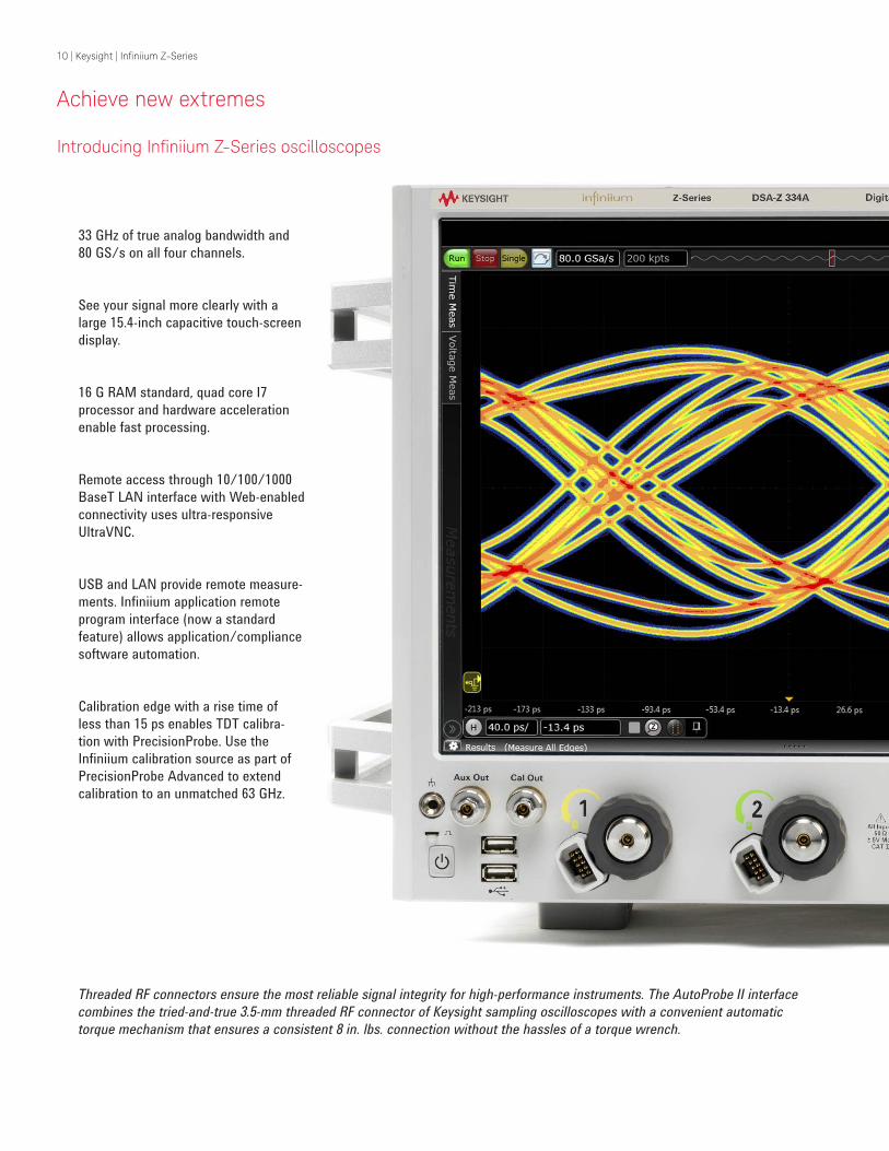
Introducing Ininiium Z-Series oscilloscopes
33 GHz of true analog bandwidth and
80 GS/s on all four channels.
See your signal more clearly with a
large 15.4-inch capacitive touch-screen
display.
16 G RAM standard, quad core I7
processor and hardware acceleration
enable fast processing.
Remote access through 10/100/1000
BaseT LAN interface with Web-enabled
connectivity uses ultra-responsive
UltraVNC.
USB and LAN provide remote measure-
ments. Infiniium application remote
program interface (now a standard
feature) allows application/compliance
software automation.
Calibration edge with a rise time of
less than 15 ps enables TDT calibra-
tion with PrecisionProbe. Use the
Infiniium calibration source as part of
PrecisionProbe Advanced to extend
calibration to an unmatched 63 GHz.
Threaded RF connectors ensure the most reliable signal integrity for high-performance instruments. The AutoProbe II interface
combines the tried-and-true 3.5-mm threaded RF connector of Keysight sampling oscilloscopes with a convenient automatic
torque mechanism that ensures a consistent 8 in. lbs. connection without the hassles of a torque wrench.
Achieve new extremes

11 | Keysight | Ininiium Z-Series Oscilloscopes - Data Sheet
The Z-Series improves upon Keysight’s use of custom integrated circuits and multichip module packaging with an exclusive
technology called RealEdge. RealEdge comprises a combination of new architectures, next-generation microcircuits and
thin-film components, and advanced application of Keysight’s indium phosphide semiconductor process. This technology
enables high-frequency capability while maintaining the industry’s lowest noise and jitter measurement floor (75 fs).
100-MHz reference clock ties up to 10
Z-Series together with 150 fs precision.
A 10-MHz clock allows tying multiple
instruments together with the
Z-Series.
Live indicator shows when the scope is
running a long operation.
Measure section, including a toggling
marker button and a dedicated marker
knob, provides quick access to your
marker control.
Individual vertical knobs per channel.
The horizontal and vertical knobs can
be changed to control functions and
waveform memories. Simply right
click the channel control in the GUI to
change these controls.

12 | Keysight | Ininiium Z-Series Oscilloscopes - Data Sheet
Ininiium user interface
Easy-to-use FFTs Amplitude demodulation Protocol decode
13 | Keysight | Ininiium Z-Series Oscilloscopes - Data Sheet
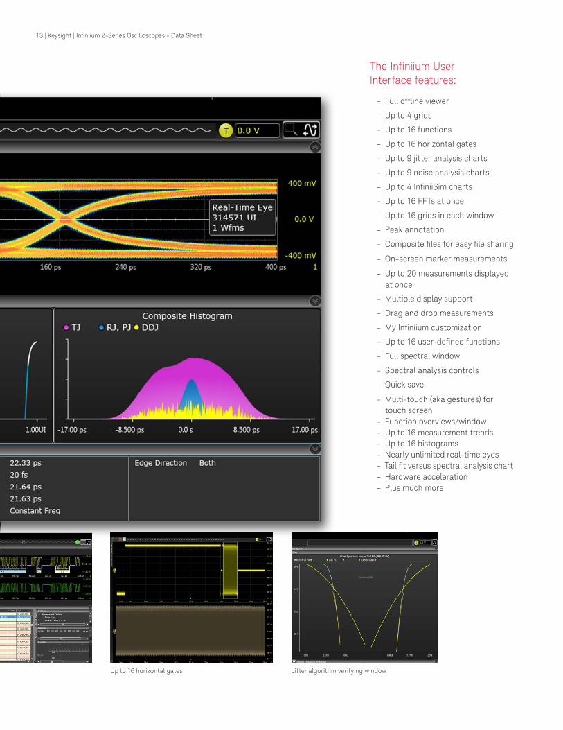
The Ininiium User Interface features:
– Full ofline viewer
– Up to 4 grids
– Up to 16 functions
– Up to 16 horizontal gates
– Up to 9 jitter analysis charts
– Up to 9 noise analysis charts
– Up to 4 IniniiSim charts
– Up to 16 FFTs at once
– Up to 16 grids in each window
– Peak annotation
– Composite iles for easy ile sharing
– On-screen marker measurements
– Up to 20 measurements displayed
at once
– Multiple display support
– Drag and drop measurements
– My Ininiium customization
– Up to 16 user-deined functions
– Full spectral window
– Spectral analysis controls
– Quick save
– Multi-touch (aka gestures) for touch screen
– Function overviews/window – Up to 16 measurement trends – Up to 16 histograms – Nearly unlimited real-time eyes – Tail it versus spectral analysis chart – Hardware acceleration – Plus much more
Protocol decode Up to 16 horizontal gates Jitter algorithm verifying window

14 | Keysight | Ininiium Z-Series Oscilloscopes - Data Sheet
Achieve new extremes
The Z-Series features the industry’s
lowest noise and jitter measurement
floors, allowing you to truly see your
signal and get your device to market
faster.
By characterizing and compensating for
loss in cables, you can gain significant
margin. PrecisionProbe makes using
switches easy in your test setup.
Debugging next-generation buses such
as PCI Express and Thunderbolt require
advanced analysis tools. Keysight’s
InfiniiSim software helps you model the
most difficult situations.
Infiniium Z-Series oscilloscopes are the world’s only 4-channel, 33-GHz real-time
oscilloscopes. Z-Series scopes are the only oscilloscopes that feature 30-GHz
probes, making debugging your system easier and ensuring you aren’t missing
valuable harmonic content.
Low noise and jitter
PrecisionProbe
Waveform transformation

15 | Keysight | Ininiium Z-Series Oscilloscopes - Data Sheet
Z-Series oscilloscopes features application-specific software that allows you to
gain the insight into your design that you need. Whether you are solving tough
jitter or noise problems, removing loss due to cables or probes, or simply looking at
protocol, the Z-Series has the tools to help you ensure you realize your best design.
Keysight’s compliance software
packages are certified by experts
and provide assurance that when you
pass in-house, you will pass at your
customer site as well.
Infiniium protocol tools simplify debug-
ging your design. Infiniium scopes
offer full protocol analysis for PCI
Express gen 1, 2, and 3. The 128b/130b
decoding features a lister that makes
alignment between the lister and
analog channels simple.
Infiniium’s new noise analysis tools
allow you to analyze your data bus
completely.
Advanced jitter and noise separation
Protocol analysis
Compliance software

16 | Keysight | Ininiium Z-Series Oscilloscopes - Data Sheet
Analysis tools: PrecisionProbe basic and advanced (options 001 and 827)
Turn your Z-Series oscilloscope into a time-domain transmissometry (TDT) and quickly characterize and compensate any input into your scope.
PrecisionProbe technology turns
your oscilloscope into the ultimate
characterization tool. Not only can you
do the normal waveform transforma-
tions such as de-embedding through
InfiniiSim, PrecisionProbe allows quick
characterization of your entire probe
system (including cables and switches)
without the need for extra equipment.
PrecisionProbe takes advantage of the
fast “cal output” signal built into the
Z-Series to characterize and compen-
sate insertion loss on the measurement
system.
PrecisionProbe technology:
– Properly creates custom probe transfer function = VOut / VIn
– Properly characterizes probed system transfer function such that VOut / VIn = VOut / VSrc
– Removes unwanted S21 cable loss
Now every probe and cable in the
system can have the exact same
response – probe to probe or cable to
PCI Express measurement comparisons
Root complex device Eye height (mV) Eye height PrecisionProbe Gain
2.5 GT/s 12 GHz 517.19 553.94 7.1%
5 GT/s_12 GHz_3.5 dB 312.22 348.19 11.5%
5 GT/s_12 GHz_6 dB 341.1 376 10.2%
5 GT/s_16 GHz_3.5 dB 306.6 348.33 13.6%
5 GT/s_16 GHz_6 dB 344.4 374.41 8.7%
8 GT/s_12 GHz_P7 96.83 103.09 6.5%
8 GT/s_12 GHz_P8 100.16 108.33 8.2%
8 GT/s_16 GHz_P7 96.92 106.01 9.4%
8 GT/s_16 GHz_P8 100.24 108.24 8.0%
By characterizing and compensating for cable loss on the cable connected to the
PCI Express test fixture, the designer was able to gain between 6.5% and 13.6%
margin that would have been lost otherwise.
cable – without the inaccuracies that
using one model can produce. You can
properly characterize custom probes
and remove unwanted responses.
In addition to characterizing the
cables, PrecisionProbe allows for
immediate use on the same instrument.
PrecisionProbe saves you time and
money while increasing your measure-
ment accuracy.
When you combine InfiniiMax probes
with switches between the amplifier
and the probe head, PrecisionProbe
allows for full correction and automa-
tion of each probe’s path. Full automa-
tion is then available to allow for quick
swapping of the inputs via Infiniium’s
compliance framework. For increased
accuracy, purchase PrecisionProbe
Advanced for faster edge speeds and
true differential measurements.
Every Z-Series oscilloscope has Keysight’s custom InP fast edge.

17 | Keysight | Ininiium Z-Series Oscilloscopes - Data Sheet
Analysis tools: EZJIT, EZJIT Plus and SDA (standard on DSA models)
Gain insight into the causes of signal jitter to ensure high reliability of your design
Measurement trends and jitter spectrumEZJIT’s simple tools help you quickly analyze the causes of
jitter. Measurement trends allow you to see deeper views of
factors affecting measurements. Jitter spectrum is a fast meth-
od to find the causes of jitter.
Two ways to separate jitterEZJIT+ comes with two ways to separate jitter: the spectral
method and the emerging tail fit method. Both methods allow
for simple separation of RJ and DJ, but the tail fit method
provides proper jitter separation in the unique case of bounded
uncorrelated jitter.
Unique RJ/DJ threshold viewEZJIT+ also provides a unique threshold view of the jitter spec-
trum with the threshold drawn on the chart. The spectral view
provides insight into the decision point of the separation and
works with both narrow and wide spectral separation.
Real-time eye and clock recoverySerial data analysis (SDA) software provides flexible clock recov-
ery including 1st and 2nd-order PLL and constant algorithms.
With a stable clock, you can look at real-time eyes of transition
and non-transition bits. Z-Series scopes with SDA software also
provide a new unique view of bits preceding an eye.
Flexible chartsEZJIT+ displays up to 10 graphs with unique information. Use
them all to maximize your jitter analysis.
Use EZJIT software to extract spread spectrum clocks.
Determine which algorithm its your data best.
Jitter separation makes debugging your device easy.
With faster edge speeds and shrinking
margins in today’s high-speed digital
designs, insight into the causes of jitter
has become critical for success. Using
EZJIT and EZJIT Plus jitter analysis
software the Z-Series oscilloscopes
help you identify and quantify jitter
margins that affect the reliability of
your design. Time correlation of jitter
to the real-time signal makes it easy to
trace jitter components to their sourc-
es. Additional compliance views and a
measurement setup wizard simplify and
automate RJ/DJ separation for testing
against industry standards.
EZJIT Plus automatically detects
embedded clock frequencies and repet-
itive data patterns on the oscilloscope
inputs and calculates the level of
data-dependent jitter (DDJ) that is con-
tributed to the total jitter (TJ) PDF by
each transition in the pattern, a feature
not available on any other real-time
oscilloscope today.

18 | Keysight | Ininiium Z-Series Oscilloscopes - Data Sheet
Analysis tools: EZJIT Complete (standard on DSA models)
Discover signal anomalies to the noise of the waveform
More than your standard jitter packageTo efficiently determine root cause for
any type of signal degradation in the
amplitude domain, you must first deter-
mine whether the problem is caused
by random or deterministic sources. To
help you accomplish this task, EZJIT
Complete takes analysis techniques
used in the time domain (jitter analysis)
and extends them into the amplitude
domain.
More than just an eye contour EZJIT Complete is an in-depth view
into impairments related to signal
levels – either logic ones or logic
zeroes – deviating from their ideal
positions. Some tools simply provide a
view of an eye contour, but provide no
real measurement data other than nice
graphics.
EZJIT Complete uses separation tech-
niques to allow each bit to be examined
to determine correlated effects and
to make multiple measurements on
individual bits to determine uncorrelat-
ed effects. Use FFTs to analyze the
frequency domain and extract random
components. Dual-Dirac modeling tech-
niques are also carried from the jitter
domain and used in the interference
domain.
Key measurementsWith EZJIT Complete, Z-Series scopes
offer the following unique measure-
ments:
– Total interference (TI)
– Deterministic interference (DI)
– Random noise (RN)
– Periodic interference (PI)
– Inter-symbol interference (ISI)
– RIN (dBm or dB/Hz)
– Q-factor

19 | Keysight | Ininiium Z-Series Oscilloscopes - Data Sheet
Analysis tools: IniniiSim (N5465A-1NL and N5465A-3NL)
The most advanced waveform transformation software helps you render waveforms anywhere in a digital serial data link
Circuit models to deine your setup The InfiniiSim waveform transformation
toolset provides a graphical user
interface for you to define your system
as you understand it and even make
it arbitrarily complex. You do this by
selecting topologies and defining circuit
blocks.
Model relectionsWith the InfiniiSim waveform trans-
formation toolset, you can transform
signals with confidence, whether you
are inserting or removing channel ele-
ments or relocating the measurement
plane. InfiniiSim’s advanced toolset lets
you model up to 27 different elements
at once and model the interaction
between elements. Only toolsets with
the ability to model more than one
element will properly reflect a model
including the oscilloscope’s input. The
Z-Series scopes provide their own s11
parameter to allow modeling of their
own input.
Model your system with as much detail as you needInfiniiSim features the model setup that
best matches your design. Whether it
is a simple single-element model or an
advanced general-purpose model with
up to 27 elements in the link, you can
perfectly model your design and simu-
late the exact probing point you want.
InfiniiSim waveform transformation toolset provides the most flexible and accurate means to render waveforms anywhere in
a digital serial data link. The highly configurable system modeling enables you to remove the deleterious effects of unwanted
channel elements, simulate waveforms with channel models inserted, view waveforms in physically improbable locations,
compensate for loading of probes and other circuit elements, and do so simply and quickly on your tool of choice, the Z-Series at
up to 63 GHz of bandwidth.

20 | Keysight | Ininiium Z-Series Oscilloscopes - Data Sheet
Analysis tools: Serial data equalization (N5461A-1NL and N5461A-1TP)
Signiicantly reduce receiver errors by opening even tightly shut eyes through equalization emulation
Serial data equalization for the Z-Series provides fast and accu-rate equalization using decision feedback equalization (DFE), feed-forward equalization (FFE), and continuous-time linear equalization (CTLE) modeling in real-time. Serial data equalization software allows you to input your own self-designat-ed tap values to verify your design. If you prefer, the software will find the optimal tap values for you. CTLE allows DC gain and two-pole modeling.
Analysis Tools: IniniiScan (N5414A-1NL and N5414A-1TP)
Trigger on events that hard-ware triggers can’t handleInfiniiScan software allows you to
use an oscilloscope to identify signal
integrity issues that hardware trigger-
ing is unable to find in your electronic
designs. This innovative software scans
through thousands of acquired wave-
forms per second to help you isolate
signal anomalies, saving you time and
improving designs.
Innovative triggersThe zone qualify finder allows you to
draw a “must pass” or “must not pass”
zone on the oscilloscope screen to
visually determine the event identify
condition. If you can see the event of
interest on the screen, you can create
a trigger that will isolate it, saving
significant time over some complicated
hardware triggers.
Other triggers include non-monotonic
edge, measurement limit search, runt
and pulse width.
Draw zones on your screen for a unique triggering experience.

21 | Keysight | Ininiium Z-Series Oscilloscopes - Data Sheet
Analysis Tools: N8900A Ininiium Ofline Oscilloscope Analysis Software
View and analyze away from your oscilloscope and target system
Ever wish you could do additional
signal viewing and analysis away from
your scope and target system? Now
you can. Capture waveforms on your
scope, save to a file, and recall into
Keysight’s Infiniium Offline application.
View and analyze anywhere your PC goes
Take advantage of large
high-resolution and multiple displays
found in your office. Use familiar
scope controls to quickly navigate and
zoom in to any event of interest. Use
auto measurements and functions for
additional insight.
Share scope measurements more easily across your team
You can share entire data records
instead of being limited exclusively to
static screen shots.
Create more useful documentation
Use features such as right-click
cut-and-paste to move screen images
between applications, without ever
having to save the image to a file.
Add up to 100 bookmark annotations
and up to 20 simultaneous
measurements.
Need advanced analysis capability?
Infiniium Offline includes a variety of
upgrade options including serial decode
upgrades for a variety of serial buses,
jitter analysis, and serial data analysis.
Ininiium Ofline software works with all of Ininiium’s applications.
Use Ininiium Ofline to ind signal anomalies, such as power supply coupling.
Peak search capability makes Ininiium Ofline a frequency domain tool.
22 | Keysight | Ininiium Z-Series Oscilloscopes - Data Sheet
Analysis tools: User-deined function (option 065)
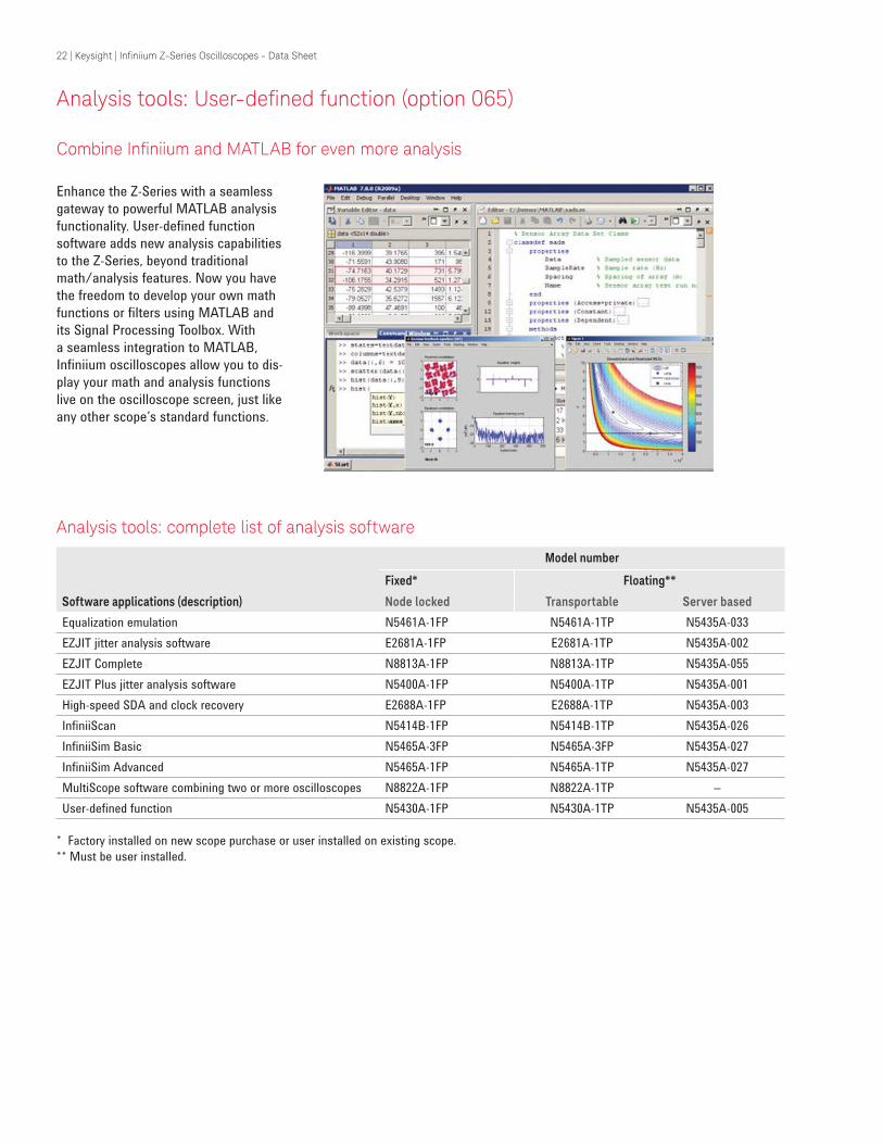
Combine Ininiium and MATLAB for even more analysis
Enhance the Z-Series with a seamless
gateway to powerful MATLAB analysis
functionality. User-defined function
software adds new analysis capabilities
to the Z-Series, beyond traditional
math/analysis features. Now you have
the freedom to develop your own math
functions or filters using MATLAB and
its Signal Processing Toolbox. With
a seamless integration to MATLAB,
Infiniium oscilloscopes allow you to dis-
play your math and analysis functions
live on the oscilloscope screen, just like
any other scope’s standard functions.
Analysis tools: complete list of analysis software
Software applications (description)
Model number
Fixed* Floating**
Node locked Transportable Server based
Equalization emulation N5461A-1FP N5461A-1TP N5435A-033
EZJIT jitter analysis software E2681A-1FP E2681A-1TP N5435A-002
EZJIT Complete N8813A-1FP N8813A-1TP N5435A-055
EZJIT Plus jitter analysis software N5400A-1FP N5400A-1TP N5435A-001
High-speed SDA and clock recovery E2688A-1FP E2688A-1TP N5435A-003
InfiniiScan N5414B-1FP N5414B-1TP N5435A-026
InfiniiSim Basic N5465A-3FP N5465A-3FP N5435A-027
InfiniiSim Advanced N5465A-1FP N5465A-1TP N5435A-027
MultiScope software combining two or more oscilloscopes N8822A-1FP N8822A-1TP –
User-defined function N5430A-1FP N5430A-1TP N5435A-005
* Factory installed on new scope purchase or user installed on existing scope.
** Must be user installed.
23 | Keysight | Ininiium Z-Series Oscilloscopes - Data Sheet
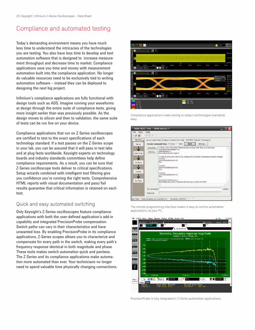
Compliance and automated testing
Compliance applications make testing to today’s technologies standards easy.
The remote programming interface makes it easy to control automation applications via your PC.
PrecisionProbe is fully integrated in Z-Series automation applications.
Today’s demanding environment means you have much
less time to understand the intricacies of the technologies
you are testing. You also have less time to develop and test
automation software that is designed to increase measure-
ment throughput and decrease time to market. Compliance
applications save you time and money with measurement
automation built into the compliance application. No longer
do valuable resources need to be exclusively tied to writing
automation software – instead they can be deployed to
designing the next big project.
Infiniium’s compliance applications are fully functional with
design tools such as ADS. Imagine running your waveforms
at design through the entire suite of compliance tests, giving
more insight earlier than was previously possible. As the
design moves to silicon and then to validation, the same suite
of tests can be run live on your device.
Compliance applications that run on Z-Series oscilloscopes
are certified to test to the exact specifications of each
technology standard. If a test passes on the Z-Series scope
in your lab, you can be assured that it will pass in test labs
and at plug fests worldwide. Keysight experts on technology
boards and industry standards committees help define
compliance requirements. As a result, you can be sure that
Z-Series oscilloscope tools deliver to critical specifications.
Setup wizards combined with intelligent test filtering give
you confidence you’re running the right tests. Comprehensive
HTML reports with visual documentation and pass/fail
results guarantee that critical information is retained on each
test.
Quick and easy automated switchingOnly Keysight’s Z-Series oscilloscopes feature compliance
applications with both the user-defined application’s add-in
capability and integrated PrecisionProbe compensation.
Switch paths can vary in their characteristics and have
unwanted loss. By enabling PrecisionProbe in its compliance
applications, Z-Series scopes allows you to characterize and
compensate for every path in the switch, making every path’s
frequency response identical in both magnitude and phase.
These tools makes switch automation quick and painless.
The Z-Series and its compliance applications make automa-
tion more automated than ever. Your technicians no longer
need to spend valuable time physically changing connections.

24 | Keysight | Ininiium Z-Series Oscilloscopes - Data Sheet
Compliance and automation testing: user-deined application (option 040)
Custom automation for your Z-Series oscilloscope
The user-defined application is the
only fully customizable automated environment made for an oscilloscope by an oscilloscope designer. It provides full automation, including the ability to control other Keysight instruments, external applications such as MATLAB
and your DUT software.
Simplify your automationThe user-defined application (UDA) makes automation simple. The appli-cation takes the Infiniium compliance application framework and gives you full access to its interface. UDA allows for automation testing in as little as one minute. Use UDA to control other Keysight instruments such as signal generators and network analyzers to
create a full suite of measurements.
Full measurement reportNo automation would be complete without a simple-to-view and easy-to-understand report. UDA provides a full report of the pass/fail
criteria you have provided.
Add-in capabilityEver wanted to add testing to your compliance applications? All Infiniium compliance applications support the industry’s most flexible testing mechanism with UDA add-in capability. Create the custom testing you need and then plug it into your compliance application to expand the application to your testing needs. UDA add-in capability is available only on Infiniium
oscilloscopes.
PrecisionProbe and switch compatibilityUDA makes automation of switches
in your system simple and accurate.
Use PrecisionProbe to characterize the
path of the switch and then let UDA’s
unique GUI switch between every input
in your switch system. Every input can
look identical in its frequency response
thanks to this advanced technology.

25 | Keysight | Ininiium Z-Series Oscilloscopes - Data Sheet
Compliance and automation testing: switch matrix support
Comprehensive testing, easily achieved
Eliminate reconnections (reducing errors)Compliance applications on the Z-Series support a switch
matrix, making testing simple by automating tests for each
lane of a multi-lane bus. Typical testing requires reconnecting
the oscilloscope each time that you switch a lane, which
causes wasted time and inaccuracies. The Z-Series solves
this problem by supporting switch matrix through its compli-
ance test. Simply connect the switch to the oscilloscope and
all the lanes, and then click run to complete full testing of
your entire device.
Maintain accuracyThe framework fully supports Keysight’s PrecisionProbe soft-
ware (N2809A) and InfiniiSim software (N5465A). This gives
you the ability to characterize every switch path to the device
under test (both magnitude and skew) and ensure that all of
them maintain the same level of accuracy.
Customize your testingUse the remote programming interface (standard feature on
the Z-Series) and N5467A user-defined application for device
control, instrument control and test customization.
Skews between switch paths are easily maintained with Keysight’s unique software.
Typical switch coniguration for HDMI testing (now supported in the Z-Series).
DUT Scope
SMAprobehead
SMAprobehead
SMAprobehead
SMAprobehead
Switch matrix+3.3V
L3 Ch4
Ch3
Ch2
Ch1
L2
L1
Clock
Software description
Model number
Fixed* Floating**
Node locked Transportable Server based
DisplayPort switch matrix U7232C-7FP U7232C-7TP N5435A-701
HDMI switch matrix N5399C-7FP N5399C-7TP N5435A-702
MIPI D-PHY switch matrix U7238C-7FP U7238C-7TP N5435A-703
MIPI M-PHY switch matrix U7249C-7FP U7249C-7TP N5435A-704
PCIe switch matrix N5393D-7FP N5393D-7TP N5435A-705
Ethernet KR switch matrix N8814B-7FP N8814B-7TP N5435A-706
QSFP+ switch matrix N6468A-7FP N6468A-7TP N5435A-707
UDA switch matrix N5467B-7FP N5467B-7TP N5435A-708
* Factory installed on new scope purchase or user installed on existing scope
** Must be user installed

26 | Keysight | Ininiium Z-Series Oscilloscopes - Data Sheet
Compliance and automation testing: other options on Z-Series oscilloscopes
In the previous pages we have highlighted a few of the key technologies that benefit from the industry’s only four-channel oscil-
loscope with more than 20 GHz bandwidth. The Z-Series offers over 20 compliance applications and the list continues to grow.
All applications are fully compatible with InfiniiSim, PrecisionProbe and UDA’s unique add-in capability.
Software description
Module number
Fixed* Floating**
Node locked Transportable Server based
PCI express compliance application for PCIe 1.0, 1.1, 2.0 and 3.0 N5393D-1FP N5393D-1TP N5435A-040
HDMI compliance application N5399C-3FP N5399C-3TP N5435A-011
HDMI 2.0 electrical performance validation and compliance N5399C-1FP N5399C-1TP -
DisplayPort source compliance test application U7232C-1FP U7232C-1TP N5435A-041
DDR and LPDDR compliance application U7233A-1FP U7233A-1TP N5435A-021
DDR2 and LPDDR2 compliance test application N5413B-1FP N5413B-1TP N5435A-037
DDR3 compliance application U7231B-1FP U7231B-1TP N5435A-053
DDR4 compliance test software application N6462A-1FP N6462A-1TP N5435A-056
GDDR5 compliance test application U7245A-1FP U7245A-1TP -
eMMC compliance application N6465A-1FP N6465A-1TP N5435A-061
MIPI D-PHY compliance application U7238C-1FP U7238C-1TP N5435A-022
MIPI M-PHY compliance application U7249C-1FP U7249C-1TP N5435A-043
SD UHS1 compliance test application U7246A-1FP U7246A-1TP -
SD UHS-II card compliance test software application N6461A-1FP N6461A-1TP N5435A-052
User-defined application N5467B-1FP N5467B-1TP N5435A-058
SATA 6Gb/s compliance N5411B-1FP N5411B-1TP N5435A-028
SAS-2 compliance test software N5412D-3FP N5412D-3TP N5435A-039
SAS-3 compliance test application N5412D-1FP N5412D-1TP N5435A-070
USB 2.0 compliance application N5416A-1FP N5416A-1TP N5435A-017
USB high-speed inter-chip interface test application U7248A-1FP U7248A-1TP N5435A-042
USB 3.1 compliance software U7243B-3FP U7243B-3TP N5435A-030
USB 3.1 10 Gbps compliance only software U7243B-1FP U7243B-1TP N5435A-030
BroadR-Reach compliance application N6467A-1FP N6467A-1TP N5435A-062
MOST compliance application for Infiniium oscilloscopes N6466A-1FP N6466A-1TP N5435A-068
Ethernet compliance application N5392B-3FP N5392B-3TP N5435A-008
Energy Efficient Ethernet (EEE) electrical performance validation/
conformance application
N5392B-1FP N5392B-1TP N5435A-060
10 GBase-T compliance application U7236A-1FP U7236A-1TP N5435A-023
Ethernet KR compliance N8814B-1FP N8814B-1TP -
SFP+ compliance application N6468A-1FP N6468A-1TP -
XAUI compliance application N5431A-1FP N5431A-1TP N5435A-018
* Factory installed on new scope purchase or user installed on existing scope
** Must be user installed

27 | Keysight | Ininiium Z-Series Oscilloscopes - Data Sheet
Software description
Module number
Fixed* Floating**
Node locked Transportable Server based
CAN/FlexRay decode N8803A-1FP N8803A-1TP N5435A-033
DigRF v4 protocol decode for Infiniium oscilloscopes N8807A-1FP N8807A-1TP N5435A-047
Ethernet 64/66 protocol and decode application N8815A-1FP N8815A-1TP N5435A-045
JTAG protocol decode N8817A-1FP N8817A-1TP N5435A-038
LLI protocol decode for Infiniium oscilloscopes N8809A-1FP N8809A-1TP N5435A-049
Low-speed serial data analysis (I²C/SPI) N5391A-1FP N5391A-1TP N5435A-006
MIPI D-PHY protocol decode N8802A-1FP N8802A-1TP N5435A-036
MIPI RFFE protocol decode N8824A-1FP N8824A-1TP N5435A-043
PCI Express 1.1 protocol decode N5463A-1FP N5463A-1TP N5435A-032
PCI Express Gen3 128/130 protocol and decode application N8816A-1FP N8816A-1TP N5435A-046
RS-232/UART protocol decode N5462A-1FP N5462A-1TP N5435A-031
UniPro protocol decode for Infiniium oscilloscopes N8808A-1FP N8808A-1TP N5435A-048
SVID trigger and decode application N8812A-1FP N8812A-1TP N5435A-054
USB 2.0 protocol decode N5464A-1FP N5464A-1TP N5435A-034
USB 3.0 SuperSpeed Inter-Chip (SSIC) protocol decode N8819A-1FP N8819A-1TP -
USB 3.0 protocol decode and trigger N8805A-1FP N8805A-1TP -
* Factory installed on new scope purchase or user installed on existing scope
** Must be user installed
Protocol analysis
Z-Series oscilloscopes come with more
than 15 protocol decoders, including
the industry’s only 64/66b decoder. The
Z-Series protocol tools feature time-cor-
related markers that let you easily move
between the listing window and the
waveform. Protocol tools can be used
on up to four lanes simultaneously.
These unique tools feature search
and trigger capability that lets you
scan through the waveform to find the
trigger condition that interests you.
Protocol tools are fully compatible with
Infiniium’s serial data analysis and are
available on the Infiniium offline tool .

28 | Keysight | Ininiium Z-Series Oscilloscopes - Data Sheet
Achieve new extremes
Conigure your high-performance real-time oscilloscope solution today
Get the most out of your oscilloscope investment by choosing options and software to speed your most common tasks. Use
option numbers when ordering at time of purchase. Use model numbers to add to an existing scope.
Choose your oscilloscope
Oscilloscope Description
DSOZ634A 63-GHz signal analyzer*
DSAZ634A 63-GHz digital signal oscilloscope
DSOZ594A 59-GHz signal analyzer*
DSAZ594A 59-GHz digital signal oscilloscope
DSOZ504A 50-GHz signal analyzer*
DSAZ504A 50-GHz digital signal oscilloscope
DSOZ334A 33-GHz signal analyzer*
DSAZ334A 33-GHz digital signal oscilloscope
DSOZ254A 25-GHz signal analyzer*
DSAZ254A 25-GHz digital signal oscilloscope
DSOZ204A 20-GHz signal analyzer*
DSAZ204A 20-GHz digital signal oscilloscope
* DSA models come standard with 100 Mpts memory, EZJIT, EZJIT Plus, EZJIT Complete and serial data analysis software.
All models come with power cord, keyboard, mouse, calibration cable, ESD strap and (5) coax adapters (5061-5311).
50 and 63 GHz models come with (2) additional 1.85 ƒ to ƒ adaptors (54932-68712)
All models come standard with removable SSD hard drive (additional hard drives can be ordered as option 827)
Description Options Model number
100 Mpts/ch memory DSOZ000-100 ** N2810-100 **
200 Mpts/ch memory DSOZ000-200 N2810-200
500 Mpts/ch memory DSOZ000-500 N2810-500
1 Gpt/ch memory DSOZ000-01G N2810-01G
2 Gpts/ch memory DSOZ000-02G N2810-02G
Description Options Model number
ANSI Z540 compliant calibration DSOZ000-A6J
ISO17025 calibration DSOZ000-1A7
Performance verification de-skew fixture for
InfiniiMax III probe
DSOX90000-808 N54443A
Rackmount kit option N2759A
Transit case N2748A
Removable SSD drive for Z-Series - 1TB DSOZ000-801
Removable SSD drive for Z-Series - 500 GB *** N2892A
Optional synchronization port for 20, 25, 33 GHz models DSOZ000-601
**Standard on DSA models.
*** 500G SSD standard.

29 | Keysight | Ininiium Z-Series Oscilloscopes - Data Sheet
Achieve new extremes
Conigure your high-performance real-time oscilloscope solution today
Upgrade your oscilloscope
Description Model numbers
Upgrades within the 90000 Z-Series family
N2764BU-025 Bandwidth upgrade -20 GHz to 25 GHz Z-Series
N2764BU-033 Bandwidth upgrade -25 GHz to 33 GHz Z-Series
N2764BU-050 Bandwidth upgrade -33 GHz to 50 GHz Z-Series
N2764BU-059 Bandwidth upgrade -50 GHz to 59 GHz Z-Series
N2764BU-062 Bandwidth upgrade -50 GHz to 63 GHz Z-Series
Multi-frame options
Description Model numbers
Upgrades within the 90000 Z-Series family
N2107A Infiniium 90000 Q- and Z-Series Multi-Frame Expansion Kit from Five to Six Frames
N2106A Infiniium 90000 Q- and Z-Series Multi-Frame Expansion Kit for Adding One Frame
N2105A Infiniium 90000 Q- and Z-Series Multi-Frame Base Kit for Stacking Two Frames
N2109A Infiniium 90000 Q- and Z-Series Sync Port Upgrade Kit for 20-33GHz Models (>33GHz Not Needed)
N2822A Infiniium Multi-Frame Software Combining Two or More Oscilloscopes
Probe heads
Model
numbers BW and input loading Key features
Differential browser head N5445A 30 GHz, Cdiff = 35fF, Cse = 50 fF, Rdiff = 100
kΩ, Rse = 50 kΩ
Z axis compliance and variable spacing from
20 mil to 125 mils, integrated LED lighting
ZIF probe head/tips N2838A 450 Ω
ceramic PCB
tip, N5439A
head, N5440A
450 Ω tip set,
N5447A 200 Ω
tip ceramic
28 GHz, Cdiff = 95fF, Cse = 130 fF, with
N2838A: Cdiff = 32fF, Cse = 44 fF, with
N5440A: Rdiff = 100 kΩ, Rse = 50 kΩ
With N5447A: Rdiff = 50 kΩ, Rse = 25 kΩ
Extremely low loading, Variable spacing from
5 mil to 80mil, User-replaceable damping
resistor tips (N2838A only)
2.92mm/3.5mm/SMA
probe head
N5444A 28 GHz, N/A, 55 Ω to Vterm Provides termination voltage of ±4V con-
trolled by scope or externally
Solder-in head N5441A
N2836A
16 GHz, Cdiff = 77 fF, Cse = 105 fF, Rdif-
f=100kΩ, Rse=50kΩ 26 GHz, Cdiff = 108 fF,
Cse = 140 fF, Rdiff=100kΩ, Rse=50kΩ
Economical and semi-permanent connection,
variable span of leads ranges from
5 mil to 80 mil
IniniiMax III probe heads
Recommended for InfiniiMax III N2800A/01A/02A/03A probe amplifiers
30 | Keysight | Ininiium Z-Series Oscilloscopes - Data Sheet
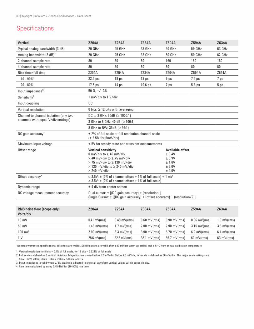
Speciications
Vertical Z204A Z254A Z334A Z504A Z594A Z634A
Typical analog bandwidth (3 dB) 20 GHz 25 GHz 33 GHz 50 GHz 59 GHz 63 GHz
Analog bandwidth (3 dB)* 20 GHz 25 GHz 32 GHz 50 GHz 59 GHz 62 GHz
2-channel sample rate 80 80 80 160 160 160
4-channel sample rate 80 80 80 80 80 80
Rise time/fall time Z204A Z254A Z334A Z504A Z594A Z634A
10 - 90%4 22.5 ps 18 ps 13 ps 9 ps 7.5 ps 7 ps
20 - 80% 17.5 ps 14 ps 10.6 ps 7 ps 5.6 ps 5 ps
Input impedance3 50 Ω, +/- 3%
Sensitivity2 1 mV/div to 1 V/div
Input coupling DC
Vertical resolution1 8 bits, ≥ 12 bits with averaging
Channel to channel isolation (any two channels with equal V/div settings)
DC to 3 GHz: 60dB (≥ 1000:1)
3 GHz to 8 GHz: 40 dB (≥ 100:1)
8 GHz to BW: 35dB (≥ 56:1)
DC gain accuracy* ± 2% of full scale at full resolution channel scale (± 2.5% for 5mV/div)
Maximum input voltage ± 5V for steady state and transient measurements
Offset range Vertical sensitivity0 mV/div to ≥ 40 mV/div> 40 mV/div to ≥ 75 mV/div> 75 mV/div to ≥ 130 mV/div> 130 mV/div to ≥ 240 mV/div> 240 mV/div
Available offset± 0.4V± 0.9V± 1.6V± 3.0V± 4.0V
Offset accuracy* ≤ 3.5V: ± (2% of channel offset + 1% of full scale) + 1 mV > 3.5V: ± (2% of channel offset + 1% of full scale)
Dynamic range ± 4 div from center screen
DC voltage measurement accuracy Dual cursor: ± [(DC gain accuracy) + (resolution)] Single Cursor: ± [(DC gain accuracy) + (offset accuracy) + (resolution/2)]
RMS noise loor (scope only)Volts/div
Z204A Z254A Z334A Z504A Z594A Z634A
10 mV 0.41 mV(rms) 0.48 mV(rms) 0.60 mV(rms) 0.90 mV(rms) 0.96 mV(rms) 1.0 mV(rms)
50 mV 1.46 mV(rms) 1.7 mV(rms) 2.00 mV(rms) 2.90 mV(rms) 3.15 mV(rms) 3.3 mV(rms)
100 mV 2.90 mV(rms) 3.3 mV(rms) 3.90 mV(rms) 5.70 mV(rms) 6.2 mV(rms) 6.4 mV(rms)
1 V 28.6 mV(rms) 32.5 mV(rms) 38.1 mV(rms) 56.7 mV(rms) 60 mV(rms) 63 mV(rms)
*Denotes warranted specifications, all others are typical. Specifications are valid after a 30-minute warm up period, and ± 5° C from annual calibration temperature
1. Vertical resolution for 8 bits = 0.4% of full scale, for 12 bits = 0.024% of full scale
2. Full scale is defined as 8 vertical divisions. Magnification is used below 7.5 mV/div. Below 7.5 mV/div, full-scale is defined as 60 mV/div. The major scale settings are
5mV, 10mV, 20mV, 50mV, 100mV, 200mV, 500mV, and 1V.
3. Input impedance is valid when V/div scaling is adjusted to show all waveform vertical values within scope display.
4. Rise time calculated by using 0.45/BW for (10-90%) rise time

31 | Keysight | Ininiium Z-Series Oscilloscopes - Data Sheet
Horizontal
Main timebase range 2 ps/div to 20 s/div real-time (RealEdge is 1 ps/div to 20 s/div real-time)
Main timebase delay range 200 s to -200 s real-time
Zoom timebase range 1 ps/div to current main time scale setting
Channel deskew ± 1 ms range, 10 fs resolution
Time scale accuracy* ± [0.1 ppm (immediately after calibration) ± 0.1 ppm/year (aging)]
Delta-time measurement accuracy
2
2
JitterSampleClockSlewRate
Noise0.35 +
⋅
2
2
JitterSampleClockSlewRate
Noise5 +
⋅
2
TimeScaleAccy Reading+
2
TimeScaleAccy Reading+ sec rms
sec rms
Delta-time measurement accuracy
ABSOLUTE
> 256 averages
Sample clock jitter Acquired time range Internal Timebase Reference External Timebase Reference
10 ms 75 fs rms 75 fs rms
10 ms - 100 ms 190 fs rms 190 fs rms
100 ms - 1 sec 500 fs rms 190 fs rms
> 1 sec 190 fs rms
Jitter measurement floor (6a,6b,6c)
2
2
+
2
2
JitterSampleClockSlewRate
Noise3 +
⋅
2
2
JitterSampleClockSlewRate
Noise2 +
⋅
TIE:
Periodic Jitter:
Cycle-Cycle:
sec rms
sec rms
sec rms
JitterSampleClockSlewRate
Noise
Speciications

32 | Keysight | Ininiium Z-Series Oscilloscopes - Data Sheet
Acquisition Z204A Z254A Z334A Z504A Z634A/Z594A
Maximum real-time sample rate
(2 channels) 80 GSa/s 160 GSa/s 2ch
(4 Channels) 80 GSa/s 80 GSa/s
Memory depth per channel 4 channels (all models) 2 channels (all models)
Standard 50 Mpts 100 Mpts
Option 100 100 Mpts (standard on DSA models) 200 Mpts (standard on DSA models)
Option 200 200 Mpts 400 Mpts
Option 500 500 Mpts 1 Gpt
Option 01G 1 Gpt 1 Gpt
Option 02G 2 Gpts 2 Gpts
Maximum acquired time at highest real-time resolution
Real-time resolution 80 GSa/s 160 GSa/s
Resolution 12.5 ps 6.25 ps
Standard (20M) 0.25 ms 0.125 ms
Option 50M 0.625 ms 0.3125 ms
Option 100 1.25 ms 0.625 ms
Option 200
Option 500
2.5 ms
6.25 ms
1.25 ms
3.125 ms
Option 01G 12.5 ms 6.25 ms
Option 02G 25 ms 12.5 ms
Sampling modes
Real-time Successive single shot acquisitions
Real-time with averaging Selectable from 2 to 65534 (up to 200,000 with function)
Real-time with peak detect 80 GSa/s (unavailable on RealEdge channels)
Real-time with hi resolution Real-time boxcar averaging reduces random noise and increases resolution (unavailable on RealEdge channels)
Gaussian magnitude, linear phase
Slower filter roll off while maintaining linear phase
Roll mode Scrolls sequential waveform points across the display in a right-to-left rolling motion. Works at sample rates up to 10 MSa/s with a maximum record length of 40 Mpts
Segmented memory Captures bursting signals at max sample rate without consuming memory during periods of inactivity Number of segments (Up to 131,072 with >500M of memory depth) Maximum time between triggers is 562,950 seconds Re-arm time: 2.5 µs Maximum memory depth: Up to 8 Gpts in 1/2 channel mode with option 02G
Filters Sin(x)/x Interpolation
On/off selectable FIR digital filter (2x, 4x, 8x 16x settings). Digital Signal Processing adds points between acquired data points to enhance measurement accuracy and waveform display
Speciications

33 | Keysight | Ininiium Z-Series Oscilloscopes - Data Sheet
Hardware trigger
Sensitivity Internal low: 2.0 div p-p 0 to 22 GHz
Internal high: 0.3 div p-p 0 to 18 GHz, 1.0 div p-p 0 to 22 GHz
Edge trigger bandwidth >20 GHz
Minimum pulse width trigger
Hardware 250 ps
Software (InfiniiScan) 40 ps
Level range Internal Auxiliary
± 4 div from center screen or ± 4 Volts, whichever is smallest ± 5 V, also limit input signal to ± 5 V
Sweep modes Auto, triggered, single
Display jitter (displayed trigger jitter)
Equal to the TIE Jitter Measurement Floor (internal edge triggering with JitterFree)
Trigger sources Channel 1, Channel 2, Channel 3, Channel 4, aux, and line
Trigger modes
Edge
Edge transition
Edge then edge (time)
Edge then edge (Event) Glitch
Pulse width
Triggers on a specified slope (rising, falling or alternating between rising and falling) and voltage level on any channel or auxiliary trigger. Edge trigger bandwidth is > 20 GHz.
Trigger on rising or falling edges that cross two voltage levels in > or < the amount of time specified. Edge transition setting from 250 ps.
The trigger is qualified by an edge. After a specified time delay between 10 ns to 10 s, a rising or falling edge on any one selected input will generate the trigger
The trigger is qualified by an edge. After a specified delay between 1 to 16,000,000 rising or falling edges, another rising or falling edge on any one selected input will generate the trigger.
Triggers on glitches narrower than the other pulses in your waveform by specifying a width less than your narrowest pulse and a polarity. Triggers on glitches as narrow as 125 ps. Glitch range settings: < 250 ps to < 10 s.
Trigger on a pulse that is wider or narrower than the other pulses in your waveform by specifying a pulse width and a polarity. Triggers on pulse widths as narrow as 125 ps. Pulse width range settings 250 ps to 10 s. Trigger point can be “end of pulse” or “time out”.
Runt Triggers on a pulse that crosses one threshold but fails to cross a second threshold before crossing the first again. Can be time qualified with minimum setting of 250 ps.
Speciications

34 | Keysight | Ininiium Z-Series Oscilloscopes - Data Sheet
Hardware trigger (continued)
Timeout
Pattern/pulse range
State
Window
Video
Trigger sequences
Trigger when a channel stays high, low, or unchanged for too long. Timeout setting: from 250 ps to 10 s.
Triggers when a specified logical combination of the channels is entered, exited, present for a specified period of time or is within a specified time range or times out. Each channel can have a value of High (H), Low (L) or Don’t care (X).
Pattern trigger clocked by the rising, falling or alternating between rising and falling edge of one channel
Triggers on an event associated with a window defined by two-user adjustable thresholds. Event can be window “entered,” “exited,” “inside (time qualified),” or “outside (time qualified)” voltage range. Trigger point can be “cross window boundary” or “time out.” Time qualify range: from 250 ps to 10 s.
Triggers from negative sync composite video, field 1, field 2, or alternating fields for interlaced systems, any field, specific line, or any line for interlaced or non-interlaced systems. Supports NTSC, PAL-M (525/60), PAL, SECAM (625/50), EDTV (480p/60), EDTV (576p/50), HDTV (720p/60), HDTV (720p/50), HDTV (1080i/60), HDTV (1080i/50), HDTV (1080p/60), HDTV (1080p/50), HDTV (1080p/30), HDTV (1080p/25), HDTV (1080p/24), and user-defined formats.
Three stage trigger sequences including two-stage hardware (Find event (A) and Trigger event (B)) and one-stage InfiniiScan software trigger. Supports all hardware trigger modes except “edge then edge” and “video,” and all InfiniiScan software trigger modes. Supports “delay (by time)” and “reset (by time or event)” between two hardware sequences. The minimum latency between “find event (A)” and “trigger event (B)” is 3 ns.
Trigger qualification AND
qualifier
Single or multiple channels may be logically qualified with any other trigger mode
Trigger holdoff range 100 nS to 10 s
Trigger actions Specify an action to occur and the frequency of the action when a trigger condition occurs. Actions include email on trigger and execute “multipurpose” user setting.
Software trigger (requires InfiniiScan event identification software – Option 009)
Trigger modes
Zone qualify
Generic serial
Measurement limit
Non-monotonic edge
Runt
Software triggers on the user-defined zones on screen. Zones can be specified as either “must intersect” or “must not intersect.” Up to eight zones can be defined across multiple channels.
Software triggers on NRZ-encoded data up to 8.0 Gbps, up to 80-bit pattern. Support multiple clock data recovery methods including constant frequency, 1st-order PLL, 2nd-order PLL, explicit clock, explicit 1st-order PLL, explicit 2nd-order PLL, Fibre Channel, FlexRay receiver, FlexRay transmitter (requires E2688A except for the constant frequency clock data recovery mode).
Software triggers on the results of the measurement values. For example, when the “pulse width” measurement is turned on, InfiniiScan measurement software trigger triggers on a glitch as narrow as 75 ps. When the “time interval error (TIE)” is measured, InfiniiScan can trigger on a specific TIE value
Software triggers on the non-monotonic edge. The non-monotonic edge is specified by setting a hysteresis value.
Software triggers on a pulse that crosses one threshold but fails to cross a second threshold before crossing the first again. Unlike hardware runt trigger, InfiniiScan runt trigger can be further qualified via a hysteresis value.
Speciications

35 | Keysight | Ininiium Z-Series Oscilloscopes - Data Sheet
Maximum measurement update
rate
> 50,000 measurement/sec (one measurement turned on)
> 250,000 measurement/sec/measurement (ten measurements turned on)
Measurement modes Standard, Measure all edges mode
Waveform measurements
voltage
Time
Clock
Data
Mixed
Frequency domain
Level qualiication
Peak to peak, minimum, maximum, average, RMS, amplitude, base, top, overshoot, preshoot, upper,
middle, lower, overshoot, Vtime, Vpreshoot, crossing, Pulse base, pulse amplitude, pulse top
Rise time, fall time, positive width, negative width, burst width, burst period, burst interval, Tmin, Tmax,
Tvolt, + pulse count, - pulse count
Period, frequency, duty cycle to duty cycle, phase, N-period
Setup time, hold time
Area, slew rate,
FFT frequency, FFT magnitude, FFT delta frequency, FFT delta magnitude, peak detect mode
Any channels that are not involved in a measurement can be used to level-qualify all timing measure-
ments
Eye-diagram measurements Eye height, eye width, eye jitter, crossing percentage, Q factor, and duty-cycle distortion
Jitter analysis measurements
Clock
Data
Requires Option 002 (or E2681A), 004 (N5400A), or 070 (N8823A). Standard on DSA Series.
Time interval error, N-period, period to period, positive width to positive width, neg width to neg width,
and duty cycle to duty cycle
Time interval error, unit interval, N Unit Interval, unit interval to unit interval, Data rate, CDR, de-empha-
sis
Statistics Displays the current, mean, minimum, maximum, range (max-min), standard deviation, number of
measurements value for the displayed automatic measurements
Histograms
Source
Orientation
Measurements
(available as a function)
Waveform or measurement
Vertical (for timing and jitter measurements) or horizontal (noise and amplitude change) modes,
regions are deined using waveform markers
Mean, standard deviation, mean ± 1, 2, and 3 sigma, median, mode, peak-to-peak, min, max, total
hits, peak (area of most hits), X scale hits, and X offset hits
Mask testing Allows pass/fail testing to user-deined or Keysight-supplied waveform templates. Automask lets you
create a mask template from a captured waveform and deine a tolerance range in time/voltage or
screen divisions. Test modes (run until) include test forever, test to speciied time or event limit, and
stop on failure. Executes “multipurpose” user setting on failure.
“Unfold real-time eye” feature will allow individual bit errors to be observed by unfolding a real-time eye
when clock recovery is on.
Communications mask test kit option provides a set of ITU-T G.703, ANSI T1.102, and IEEE 802.3
industry-standard masks for compliance testing.
Waveform math
Number of functions
Hardware accelerated math
operations
Sixteen
Differential and Common Mode
Absolute value, add, amplitude demodulation (radar envelope), average, Butterworth*, common mode,
delay, differentiate, divide, FFT magnitude, FFT, phase, FIR*, high pass ilter, histogram, horizontal gating,
integrate, invert, LFE*, low pass ilter (4th-order Bessel Thompson ilter), magnify, max, measurement
trend, min, multiply, RT Eye*, smoothing, SqrtSumOfSquare*, square, square root, subtract, versus, and
optional user deined function (Option 010)
FFT
Frequency range
Frequency resolution
Window modes
DC to 80 GHz (at 160 GSa/s) or 40 GHz (at 80 GSa/s) or 20 GHz (at 40 GSa/s)
Sample rate/memory depth = resolution
Hanning, lattop, rectangular, Blackman-Harris, Hamming
Speciications

36 | Keysight | Ininiium Z-Series Oscilloscopes - Data Sheet
Measurement modes
Automatic measurements
Multipurpose
Drag-and-drop measurement ...toolbar
Measure menu access to all measurements, up to 20 measurements can be displayed simultaneously
Front-panel button activates up to ten pre-selected or up to ten user-deined automatic measurements
Measurement toolbar with common measurement icons that can be dragged and dropped onto the displayed waveforms
Marker modes Manual markers, track waveform data, track measurements
Bookmarks and callouts Supports callouts for measurements and FFT peaks. Supports bookmarks for team collaboration
Display
Display 15.4-inch color XGA TFT-LCD with capacitive touch screen
Intensity grayscale 256-level intensity-graded display
Resolution XGA 1024 pixels horizontally x 768 pixels vertically
Annotation Up to 12 labels, with up to 100 characters each, can be inserted into the waveform area
Displays Supports up to 12 display windows (waveform/function, spectral, color grade, chart (jitter/InfiniiSim), measurement)
Grids Choose between 1-16 grids per waveform area, 8 bit vertical resolution
Waveform styles Connected dots, dots, infinite persistence, color graded infinite persistence. Includes up to 256 levels of intensity-graded waveforms., variable persistence
Waveform area Supports eight waveform areas plus chart mode for EZJIT Plus, InfiniiSim, protocol, and PrecisionProbe
Maximum update rate > 400,000 waveforms per second (when in the segment memory mode)
Computer system and peripherals, I/O ports
Computer system and peripherals Operating system
CPU
PC system memory
Drives (SSD)
Peripherals
Windows Seven
Intel i5-35505
16 GB DDR3 RAM
500-GB internal hard drive removable hard drive, additional hard drives (N2746A)
Logitech optical USB mouse, compact USB keyboard supplied. All Infiniium modelssupport any Windows-compatible input device with a serial, PS/2 or USB interface.
File types
Waveforms Images
Compressed internal format (*.wfm (200 Mpts)), comma-separated values (*.csv (2 Gpts)), tab-separated values (*.tsv (2 Gpts)), public binary format (.bin (500 Mpts)), Y value files (*.txt (2 Gpts)),hierarchal data file (*.hf5 (2 Gpts)), composite data file (*.osc (2 Gpts))
BMP, PNG, TIFF, GIF, JPEG or osc file format
Speciications

37 | Keysight | Ininiium Z-Series Oscilloscopes - Data Sheet
I/O ports
RS-232 (serial), Parallel, PS/2, USB 2.0 hi-speed (host), USB 2.0 hi-speed (device), VGA, DisplayPort,
USB 3.0, Dual-monitor video output, Auxiliary output, Trigger output, Time base reference output
Speciications
General characteristics
Temperature Operating: 5 °C to + 40 °C; Non-operating: –40°C to +65 °C
Humidity Operating: up to 95% relative humidity (non-condensing) at +40 °C; Non-operating:
up to 90% relative humidity at +65 °C
Altitude Operating: up to 4,000 meters (12,000 feet); Non-operating: up to 15,300 meters (50,000 feet)
Vibration Operating random: 00.21 g(rms)
Non-operating random: 2.0 g(rms)
Swept sines: (0.50g)
Power 100-240 VAC ± 10% at 50/60 Hz
Maximum input power 1350 Watts
Well-regulated power is required for 100 - 120 VAC operation
Weight 71 lbs
Dimensions 20” wide, 13.3” tall, and 19.4” deep
Safety CAN/CSA-C22.2 No. 61010-1-04 UL Std. No. 61010-1 (2nd Edition)
Keysight Technologies Oscilloscopes
Multiple form factors from 20 MHz to > 90 GHz | Industry leading specs | Powerful applications

For more information on Keysight Technologies’ products, applications or services, please contact your local Keysight office. The complete list is available at:www.keysight.com/find/contactus
Americas Canada (877) 894 4414Brazil 55 11 3351 7010Mexico 001 800 254 2440United States (800) 829 4444
Asia PaciicAustralia 1 800 629 485China 800 810 0189Hong Kong 800 938 693India 1 800 112 929Japan 0120 (421) 345Korea 080 769 0800Malaysia 1 800 888 848Singapore 1 800 375 8100Taiwan 0800 047 866Other AP Countries (65) 6375 8100
Europe & Middle EastAustria 0800 001122Belgium 0800 58580Finland 0800 523252France 0805 980333Germany 0800 6270999Ireland 1800 832700Israel 1 809 343051Italy 800 599100Luxembourg +32 800 58580Netherlands 0800 0233200Russia 8800 5009286Spain 0800 000154Sweden 0200 882255Switzerland 0800 805353
Opt. 1 (DE)Opt. 2 (FR)Opt. 3 (IT)
United Kingdom 0800 0260637
For other unlisted countries:www.keysight.com/find/contactus(BP-09-04-14)
38 | Keysight | Ininiium Z-Series Oscilloscope - Data Sheet
This information is subject to change without notice.© Keysight Technologies, 2014Published in USA, September 4, 20145991-3868ENwww.keysight.com
myKeysight
www.keysight.com/find/mykeysight
A personalized view into the information most relevant to you.
www.axiestandard.org
AdvancedTCA® Extensions for Instrumentation and Test (AXIe) is an open standard that extends the AdvancedTCA for general purpose and semiconductor test. Keysight is a founding member of the AXIe consortium. ATCA®, AdvancedTCA®, and the ATCA logo are registered US trademarks of the PCI Industrial Computer Manufacturers Group.
www.lxistandard.org
LAN eXtensions for Instruments puts the power of Ethernet and the Web inside your test systems. Keysight is a founding member of the LXI consortium.
www.pxisa.org
PCI eXtensions for Instrumentation (PXI) modular instrumentation delivers a rugged, PC-based high-performance measurement and automation system.
Three-Year Warranty
www.keysight.com/find/ThreeYearWarranty
Keysight’s commitment to superior product quality and lower total cost of ownership. The only test and measurement company with three-year warranty standard on all instruments, worldwide.
Keysight Assurance Plans
www.keysight.com/find/AssurancePlans
Up to five years of protection and no budgetary surprises to ensure your instruments are operating to specification so you can rely on accurate measurements.
www.keysight.com/go/quality
Keysight Technologies, Inc.DEKRA Certified ISO 9001:2008 Quality Management System
Keysight Channel Partners
www.keysight.com/find/channelpartners
Get the best of both worlds: Keysight’s measurement expertise and product breadth, combined with channel partner convenience.
www.keysight.com/find/Z-Series