Embed Size (px)
Citation preview

Keysight 16860A SeriesPortable Logic Analyzers
Data Sheet

Introduction
Models 16861A 16862A 16863A 16864AChannels 34 68 102 136Max timing sample rate 2.5 GHz full channel/5.0 GHz half channelQuarter channel timing sample rate
— 10 GHz (Option T10)
— 10 GHz (Option T10)
Max state clock rate 350 MHz standard, 700 MHz (Option 700)Maximum state data rate 700 Mb/s standard, 1400 Mb/s (Option 700)Timing zoom 12.5 GHz at 256 K deepMemory depth 2 Mb standard; 4 Mb, 8 Mb, 16 Mb, 32 Mb, 64 Mb, 128 Mb optional
(2x in half-channel timing, 4x in quarter-channel timing)Probe/signal compatibility U4200A Series single-ended direct connect probes, 90-pin single-ended and differential
probes
Keysight’s 16860A Series is the industry’s highest-performance portable logic analyzer – providing you the best insight so you can solve your toughest digital debug challenges.
– High-speed state and timing with deep memory – Capture the most system activity (up to 128 Mb) at the highest resolution to identify the root cause of a problem and symptom widely separated in time
– Signal integrity – Quickly identify problem signals with simultaneous eye diagrams on all channels – Probing and application support – Customize a system for your specific needs with a comprehensive set
of probing options and application-specific software – Upgradable – Purchase the capability you need now, then upgrade as your needs evolve

03 | Keysight | 16860A Series Portable Logic Analyzers - Data Sheet
As timing and voltage margins continue to shrink, confidence in signal integrity becomes an increasingly vital requirement in the design validation process. Eye scan lets you acquire signal integrity information on all the buses in your design (and under a wide variety of operating conditions) in a matter of minutes. Identify problem signals quickly for further investigation with an oscilloscope. Results can be viewed for each individual signal or as a composite of multiple signals or buses.
Figure 1. Eye scan automatically sets sample positions for accurate state capture and also provides a signal integrity view of each input signal, without the need for an oscilloscope.
Identify Problem Signals on All Channels Simultaneously
04 | Keysight | 16860A Series Portable Logic Analyzers - Data Sheet
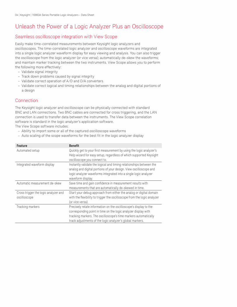
Unleash the Power of a Logic Analyzer Plus an Oscilloscope
Seamless oscilloscope integration with View ScopeEasily make time-correlated measurements between Keysight logic analyzers and oscilloscopes. The time-correlated logic analyzer and oscilloscope waveforms are integrated into a single logic analyzer waveform display for easy viewing and analysis. You can also trigger the oscilloscope from the logic analyzer (or vice versa); automatically de-skew the waveforms; and maintain marker tracking between the two instruments. View Scope allows you to perform the following more effectively:
– Validate signal integrity – Track down problems caused by signal integrity – Validate correct operation of A/D and D/A converters – Validate correct logical and timing relationships between the analog and digital portions of
a design
ConnectionThe Keysight logic analyzer and oscilloscope can be physically connected with standard BNC and LAN connections. Two BNC cables are connected for cross triggering, and the LAN connection is used to transfer data between the instruments. The View Scope correlation software is standard in the logic analyzer’s application software.The View Scope software includes:
– Ability to import some or all of the captured oscilloscope waveforms – Auto scaling of the scope waveforms for the best fit in the logic analyzer display
Feature BenefitAutomated setup Quickly get to your first measurement by using the logic analyzer’s
Help wizard for easy setup, regardless of which supported Keysight oscilloscope you connect to.
Integrated waveform display Instantly validate the logical and timing relationships between the analog and digital portions of your design. View oscilloscope and logic analyzer waveforms integrated into a single logic analyzer waveform display.
Automatic measurement de-skew Save time and gain confidence in measurement results with measurements that are automatically de-skewed in time.
Cross trigger the logic analyzer and oscilloscope
Start your debug approach from either the analog or digital domain with the flexibility to trigger the oscilloscope from the logic analyzer (or vice versa).
Tracking markers Precisely relate information on the oscilloscope’s display to the corresponding point in time on the logic analyzer display with tracking markers. The oscilloscope’s time markers automatically track adjustments of the logic analyzer’s global markers.

05 | Keysight | 16860A Series Portable Logic Analyzers - Data Sheet
Debug, Verify, and Optimize DDR, LPDDR, and ONFi Memory Systems
Supported memory device speeds for 16860A Series logic analyzersMemory family Memory device
clock rateMemory device data rate
Required state speed option350 MHz clock standard
700 MHz clock Option 700
DDR < 350 MHz < 700 Mb/s √ √DDR2 < 350 MHz < 700 Mb/s √ √DDR3 < 700 MHz < 1400 Mb/s √LPDDR < 350 MHz < 700 Mb/s √ √LPDDR2 < 700 MHz < 1400 Mb/s √LPDDR3 < 700 MHz < 1400 Mb/s √
The 16860A Series logic analyzers, in conjunction with memory specific probing solutions and B4661A Memory Analysis Software, provide a cost-effective platform for debugging, verifying and optimizing memory designs operating at ≤ 1400 MT/s. You can get a comprehensive view into your system’s memory operation with bus decode, transaction overview, compliance testing and performance analysis.
The 16860A Series supports Add/Cmd/Data state mode measurements for the following DDR and LPDDR memory families. For higher speed or channel count DDR/2/3, LPDDR/2/3, DDR4 and LPDDR4 memory applications, refer to Keysight’s U4164A logic analyzer module which is designed specifically for high-speed memory applications.
In addition, the 2.5 GHz timing mode provides a 3:1 ratio of sample rate to data rate so you can perform timing measurements on DDR/LPDDR devices with < 400 MHz clock rate/ < 800 Mb/s data rate. When a 16862A or 16864A logic analyzer is configured with the 10 GHz quarter channel timing option, the analyzer is capable of capturing Open NAND Flash Interface (ONFi) traffic. Analysis of captured ONFi traffic is provided through the Performance Analysis option (4FP/4NP/4TP) of the B4661A Memory Analysis Software.

06 | Keysight | 16860A Series Portable Logic Analyzers - Data Sheet
Get Instant Insight into your Design with Multiple Views and Analysis Tools
When you want to understand what your target is doing and why, you need acquisition and analysis tools that rapidly consolidate data and provide insight into your system’s behavior.
Optional analysis and automated measurement packagesB4601C Serial to parallel analysis package. This general purpose software enables easy viewing
and analysis of serial data by converting it into a parallel format, thereby eliminating the tedious, time-consuming, and error-prone task of sifting through thousands of captured 1’s and 0’s.
B4602A Signal extractor tool. This tool processes input signals and based on xml algorithms and creates a mapping of captured signals into new bus and signal names.
B4610A Data import package. Use the logic analyzer GUI to view data obtained from tools other than a logic analyzer.
B4655A B4656A
FPGA dynamic probe application software for Xilinx (B4655A) and Altera (B4656A). The FPGA dynamic probe provides unprecedented visibility into your FPGA’s internal activity. Make incremental real-time measurements in seconds without stopping the FPGA, changing the design or modifying design timing. Quickly set up the logic analyzer with automatic pin mapping and signal bus naming by leveraging the work you did in your design environment.
B4661A Memory Analysis Software for logic analyzers. This package includes standard and optional licensed software. Standard features are always available for use. Optional licensed features require the purchase of a license to enable the full functionality of the option. Options include:
– DDR decoder with physical address trigger tool – LPDDR decoder – DDR and LPDDR compliance violation analysis – DDR3/4 and LPDDR2/3/4 performance analysis
89601B-300 Digital vector signal analysis software, hardware connectivity for logic analyzers. Perform time-domain, spectrum and modulation quality analysis on digital baseband and IF signals with Keysight’s 89600 Vector Signal Analysis software, running on the logic analyzer. www.keysight.com/find/dvsa

07 | Keysight | 16860A Series Portable Logic Analyzers - Data Sheet
16860A Series Logic Analyzer Specifications and Characteristics
State (synchronous) sampling mode16861A 16862A 16863A 16864A
Channels 34(32 data and 2 clock)
68(64 data and 4 clock)
102 (96 data and 6 clock)
136(128 data and 8 clock)
Sampling option: Single clockClock (clock is on Pod 1) 1 1 1 1Clock qualifiers 1 3 4 4Reset qualifier 0 0 0 1Sampling option: Multiple clocksClocks or clock qualifiers 2 4 4 4Reset qualifier 0 0 0 0
Clock channels can be used as data channels.
The state sampling clock mode specifies how the clock inputs are used for sampling. The availability of these state sampling clock modes depends on the state sampling option that you select.
– Master - All pods sampled by the master clock definition. – In single clock mode, only the clock signal on Pod 1 can be used. – In multiple clocks, either a single clock signal can be used or a combination of clocks
can be used. – Dual sample - In the dual sample clock mode, you can capture two samples per clock
edge with two different threshold offsets and separate sampling positions. These separate threshold offsets and sampling positions allow you to set independent thresholds and sampling positions for Read and Write in DDR/LPDDR captures and for Rising and Falling edge in general-purpose data captures.
– Master/slave - Master pod is sampled on master clock and slave pod is sampled on slave clock, but the captured data of both slave and master clocks is saved together when the master clock occurs.
– Demux - Data being probed by one pod is demultiplexed into the logic analyzer memory that is normally used for two pods. The demultiplex mode uses the master and slave clocks to demultiplex the data.
350 MHz (Base configuration)
700 MHz (Option 700)
350 MHz (Base configuration)
Sampling option Single clock Single clock Multiple clocksAvailable clock modes Master Master Master
Dual sample Dual sample Master/slaveDemux
Maximum state data rate (spec) 1
Captures data up to 350 Mbps on either edge of a clock up to 350 MHz
Captures data up to 700 Mbps on either edge of the clock up to 700 MHz
Captures data up to 700 Mbps on any combination of multiple clocks up to 350 MHz
Captures data up to 700 Mbps on both edges of a clock up to 350 MHz
Captures data up to 1400 Mbps on both edges of the clock up to 700 MHz
Maximum state clock frequency
350 MHz 700 MHz 350 MHz
Minimum state clock frequency
12.5 MHz (single edge), 6.25 MHz (both edges)
12.5 MHz (single edge), 6.25 MHz (both edges)
0 MHz
Minimum time between active clock edges
1430 ps 715 ps 1430 ps
Maximum trigger sequencer speed
700 MHz 1400 MHz 700 MHz
1. Specification (spec): Represents warranted performance of a calibrated instrument that has been stored for a minimum of 2 hours within the operating temperature range of 5 to 40 °C, unless otherwise stated, and after a 45-minute warm-up period. The specifications include measurement uncertainty.

08 | Keysight | 16860A Series Portable Logic Analyzers - Data Sheet
State mode functional characteristics
Single clock Multiple clocksMinimum setup time 80 ps 250 psMinimum hold time 80 ps 250 psMinimum data valid window 160 ps 500 psSample position adjustment range 7 ns typical 12 ns typicalSample position adjustment resolution 20 ps typical 80 ps typicalMinimum state clock pulse width Single edge: 200 ps Single edge: 250 psClock qualifier setup time 200 ps 250 psClock qualifier hold time 200 ps 250 psRESET clock qualifier setup time 2 ns N/ARESET clock qualifier hold time 0 ps N/AMinimum slave to master clock time N/A 350 psMinimum master to slave clock time N/A 150 psMinimum slave to slave clock time N/A 1.43 nsTime tag resolution 80 ps 80 psMaximum time count between stored states 66 days 66 daysMaximum trigger sequence steps 8 16Trigger sequence step branching Arbitrary 4-way if/then/else Arbitrary 4-way if/then/elseTrigger position Start, center, end or user-defined Start, center, end or user-definedTrigger resources – 16 patterns evaluated as =, !=, >,
>=, <, <= – 8 double-bounded ranges
evaluated as in range, not in range – 4 edge detectors in timing, 3 in
transitional timing – 1 occurrence counter per sequence
level – 1 timer – 4 flags – 1 arm in – Burst patterns – Event counters - 2
– 16 patterns evaluated as =, !=, >, >=, <, <= – 8 double-bounded ranges evaluated as in range, not in
range – 4 edge detectors in timing, 3 in transitional timing – 1 occurrence counter per sequence level – 3 timers – 4 flags – 1 arm in – Global counters - 2
Maximum occurrence counter 999,999,999 999,999,999Maximum range width 64 bits 64 bitsMaximum pattern width 128 bits single label 128 bits single labelTimer range 200 sample clock period to 27 hours 100 ns to 27 hoursTimer resolution 5 ns 5 nsTimer accuracy ± (8 sample clock period + 2 ns + 0.01%) ± (8 sample clock period + 2 ns + 0.01%)Timer reset latency 80 sample clock period 80 sample clock period
16860A Series Logic Analyzer Specifications and Characteristics (Continued)
09 | Keysight | 16860A Series Portable Logic Analyzers - Data Sheet
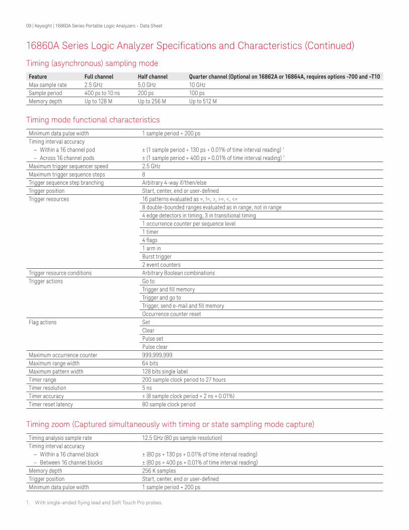
Timing mode functional characteristics
Minimum data pulse width 1 sample period + 200 psTiming interval accuracy
– Within a 16 channel pod ± (1 sample period + 130 ps + 0.01% of time interval reading) 1
– Across 16 channel pods ± (1 sample period + 400 ps + 0.01% of time interval reading) 1
Maximum trigger sequencer speed 2.5 GHzMaximum trigger sequence steps 8Trigger sequence step branching Arbitrary 4-way if/then/elseTrigger position Start, center, end or user-definedTrigger resources 16 patterns evaluated as =, !=, >, >=, <, <=
8 double-bounded ranges evaluated as in range, not in range4 edge detectors in timing, 3 in transitional timing1 occurrence counter per sequence level1 timer4 flags1 arm inBurst trigger2 event counters
Trigger resource conditions Arbitrary Boolean combinationsTrigger actions Go to
Trigger and fill memoryTrigger and go toTrigger, send e-mail and fill memoryOccurrence counter reset
Flag actions SetClearPulse setPulse clear
Maximum occurrence counter 999,999,999Maximum range width 64 bitsMaximum pattern width 128 bits single labelTimer range 200 sample clock period to 27 hoursTimer resolution 5 nsTimer accuracy ± (8 sample clock period + 2 ns + 0.01%)Timer reset latency 80 sample clock period
Timing (asynchronous) sampling mode
Feature Full channel Half channel Quarter channel (Optional on 16862A or 16864A, requires options -700 and –T10Max sample rate 2.5 GHz 5.0 GHz 10 GHzSample period 400 ps to 10 ns 200 ps 100 psMemory depth Up to 128 M Up to 256 M Up to 512 M
16860A Series Logic Analyzer Specifications and Characteristics (Continued)
Timing zoom (Captured simultaneously with timing or state sampling mode capture)
Timing analysis sample rate 12.5 GHz (80 ps sample resolution)Timing interval accuracy
– Within a 16 channel block ± (80 ps + 130 ps + 0.01% of time interval reading) – Between 16 channel blocks ± (80 ps + 400 ps + 0.01% of time interval reading)
Memory depth 256 K samplesTrigger position Start, center, end or user-definedMinimum data pulse width 1 sample period + 200 ps
1. With single-ended flying lead and Soft Touch Pro probes.

10 | Keysight | 16860A Series Portable Logic Analyzers - Data Sheet
16860 Series Instrument Characteristics
Standard data viewsWaveform Integrated display of data as digital waveforms, analog waveforms imported from an external
oscilloscope, and/or as a chart of a bus’ values over timeListing Displays data as a state listingCompare Compares data from different acquisitions and highlights differencesSource code Displays time-correlated source code and inverse assembly simultaneously in a split display
Define the trigger event by simply clicking on a line of source codeObtain source-code-level views of dynamically loaded software or code moved from ROM to RAM during a boot-up sequence using address offsetsRequires access to source files via the LAN or instrument hard drive to provide source code correlationSource correlation does not require any modification or recompilation of your source code
Eye scan Displays eye diagrams across all buses and signals simultaneously, allowing you to identify problem signals quickly
Data displayNumeric bases for data display Binary, hex, octal, decimal, signed decimal (two’s complement), ASCII, symbols and processor
mnemonicsSymbolic support/object file format compatibilityNumber of symbols/ranges Unlimited (limited only by amount of virtual memory available on 16860 Series logic analyzers)Object file formats supported IEEE-695, Aout, Omf86, Omf96, Omf386, Sysrof, ELF/DWARF1 1, ELF/DWARF2 1, ELF/Stabs1, ELF/
Stabs2, ELF/Mdebug Stabs, TICOFF/COFF, TICOFF/StabsASCII GPA (general purpose ASCII)User-defined symbols Specify a mnemonic for a given bit pattern for a label or busAvailable data/file formatsala Contains information to reconstruct the display appearance, instrument settings and trace data
(optional) that were present when the file was createdxml Extensible markup language for configuration portability and programmabilitycsv CSV (comma-separated values) format for transferring data to other applications like Microsoft Excelalb Export logic analyzer data for post-processing. Alb data (module binary format) can be parsed using
programming toolsStandard analysis toolsFilter/colorize Show, hide or color certain samples in a trace for easier identification and analysisFind (next/previous) Locate specific data/events in a captured trace
1. Supports C++ name de-mangling.

11 | Keysight | 16860A Series Portable Logic Analyzers - Data Sheet
16860 Series Instrument Characteristics (Continued)
16860A Series PC characteristicsOperating system Microsoft Windows 7 embedded (64-bit)Processor 3 GHz Intel i5 quad core processorChipset Intel Q77System memory 8 GBRemovable SSD 256 GBInstalled on SSD Operating system, latest revision of the logic and protocol application software, optional application
software ordered with the logic analyzer16860A Series instrument controlsLCD touch-screen display Large 38.1-cm (15-in.) touch-screen display makes is easy to view a large number of waveforms or
statesFront-panel hot keys Dedicated hot keys for selecting run mode and disabling touch screenFront-panel knob General-purpose knob adjusts viewing and measurement parametersKeyboard and mouse USB keyboard and USB mouse16860A Series video display modesTouch-screen display standard Size: 38.1-cm (15-in.)
Resolution: 1024 x 768External display Simultaneous display capability; Front panel and external
ProgrammabilityYou can write programs to control the logic analyzer application from remote computers on the local area network using COM. The COM automation server is part of the logic analyzer application. This software allows you to write programs to control the logic analyzer. All measurement functionality is controllable via the COM interface.
The remote programming interface works through the COM automation objects, methods and properties provided for controlling the logic analyzer application.

12 | Keysight | 16860A Series Portable Logic Analyzers - Data Sheet
16860A Series Interfaces
Peripheral interfacesDisplay One 15-pin XGA connector and one DisplayPort connectorAudio ports Line in, line out, mic inUSB ports Two 3.0 ports on rear, two 2.0 ports on front, two 2.0 ports on rearConnectivity interfacesLAN 10Base-T, 100Base-T, 1000Base-TConnector RJ-45Interface with external instrumentationTrigger or arm external devices or receive signals that can be used to arm measurement hardware within the logic analyzer with trigger in/outTrigger inInput Rising edge or falling edgeAction taken When received, the logic analyzer takes the actions described in the trigger sequence stepInput signal level ± 6 V maxThreshold level Selectable: ECL, LVPECL, LVTTL, PECL, TTL
User defined (± 5 V in 50 mV increments)Minimum signal amplitude 200 mVConnector BNCInput resistance 3.2 kΩ nominalTrigger outTrigger Select one event from the following as the trigger out event: logic analyzer trigger, flag 1, flag 2, flag 3 or
flag 4Mode FeedthroughPolarity Active highOutput signal VOH (output high level) 2.0 V min
VOL (output low level) 0.5 V maxSignal load 50 Ω (For good signal quality, the trigger out signal should be terminated in 50 Ω to ground)Connector BNCExternal reference clock in
10 MHz ± 0.01%Signal swing Minimum 200 mVp-p swing, Maximum 5 Vp-p swingConnector BNC

13 | Keysight | 16860A Series Portable Logic Analyzers - Data Sheet
Dimensions16861A, 16862A, 16863A, 16864A
Height 291.57 mm (11.48 in)Width 450.65 mm (17.74 in)Add 1.25 inches to the width to account for probes that plug into the right side of the instrumentDepth 456.54 mm (17.97 in)
Power16861A 100 to 120 V ± 10%, 50/60/400 Hz
100 to 240 V ± 10% 50/60 Hz325 W max
16862A 100 to 120 V ± 10%, 50/60/400 Hz100 to 240 V ± 10% 50/60 Hz325 W max
16863A 100 to 120 V ± 10%, 50/60/400 Hz100 to 240 V ± 10% 50/60 Hz325 W max
16864A 100 to 120 V ± 10%, 50/60/400 Hz100 to 240 V ± 10% 50/60 Hz325 W max
Weight Max net Max shipping16861A 12.5 kg (27.6 lbs) 23.3 kg (51 lbs)16862A 12.5 kg (27.6 lbs) 23.3 kg (51 lbs)16863A 12.5 kg (27.6 lbs) 23.3 kg (51 lbs)16864A 12.5 kg (27.6 lbs) 23.3 kg (51 lbs)
Instrument operating environmentTemperature Operating 5 °C to 40 °C
Non-operating –40 °C to +65 °COperating up to 90% relative humidity (non-condensing) at 40 °C
Humidity Operating up to 90% relative humidity (non-condensing) at 40 °CNon-operating up to 90% relative humidity (non-condensing) at 65 °C
Altitude Operating up to 4000 meters (13,000 ft)Non-operating up to 15300 meters (50,000 ft)
Extra notes regarding 16860A Series:1. Pollution degree 22. Installation category II3. These instruments are intended for use in an indoor lab environment
16860A Series Physical Characteristics

14 | Keysight | 16860A Series Portable Logic Analyzers - Data Sheet
Ordering Information
A complete logic analysis system includes the logic analyzer, probes, optional application software and accessories. Use the information on the following pages to configure a portable logic analysis system.
16860A Series portable logic analyzerThe base configuration of each 16860A Series logic analyzer includes 350 MHz state, 2.5 GHz timing (full channel) and 2 Mb memory depth standard.
Configuring a logic analyzer to meet your application needs and budget is as easy as 1, 2, 3.1. Select a channel count to determine the model number. Once the model number is
determined, use the entries in that column for the remaining configuration selections.2. Select the desired state and timing speeds. Note: 10 GHz quarter channel timing mode is
available on the 16862A and 16864A models only.3. Select the memory depth. Memory depth is defaulted to 2 Mb if no selection is made.
Model 16861A 16862A 16863A 16864AChannelsChannels 34 68 102 136State speed350 MHz Standard Standard Standard Standard700 MHz 16861A-700 16862A-700 16863A-700 16864A-700Timing speed (quarter channel mode)10 GHz — 16862A-T10 1 — 16864A-T10 1
Memory depth2 Mb Standard Standard Standard Standard4 Mb 16861A-004 16862A-004 16863A-004 16864A-0048 Mb 16861A-008 16862A-008 16863A-008 16864A-00816 Mb 16861A-016 16862A-016 16863A-016 16864A-01632 Mb 16861A-032 16862A-032 16863A-032 16864A-03264 Mb 16861A-064 16862A-064 16863A-064 16864A-064128 Mb 16861A-128 16862A-128 16863A-128 16864A-128
1. Option 16862A-T10 requires 16862A-700. Option 16864A-T10 requires 16864A-700.
Each 16860 Series logic analyzer includes the following: – USB keyboard – USB mouse – Accessory bag – Power cord

15 | Keysight | 16860A Series Portable Logic Analyzers - Data Sheet
16860A Series Probing Options
Logic analyzer probes are required and ordered separately. Please specify probes when ordering to ensure the correct connection between the logic analyzer and the device under test.
Consider the following when determining how you’ll connect to the DUT. For more detailed information on probing options, please refer to the Probing Solutions for Logic Analyzers data sheet (pub number: 5968-4632E).
Flying lead probesMeasure individual signals physically far apart or located where a probe connector hasn’t been designed in. A wide variety of accessories provide the flexibility to connect to IC pins, traces, pads, vias and any signal that resides on the surface of the board.
Soft Touch connectorless probesSoft Touch connectorless probes ensure signal quality with < 0.7 pF of capacitive loading. They are compatible with all surface finishes, including lead-free. The probe requires a soft touch footprint designed into your target system.
Connector probes – SamtecThis high-performance connector solution supports data rates up to 1.5 Gb/s. The probe requires a 100-pin Samtec connector designed into your target system.
Connector probes – MictorThis reliable and cost-effective connector solution supports data rates up to 600 Mb/s. Mictor probes require a 38-pin Mictor connector designed into your target system.
DDR/LPDDR BGA probesBGA probes work in existing designs and eliminate the need for up front planning or re-design. BGA probes allow you to get signal access to the DDR/LPDDR signals, connecting directly to the balls of the DRAM, enabling you to operate at full speed and acquire high-speed signals without impacting the performance of your design.ZIF probesZIF probes provide convenient and reliable connection between the BGA probe wings and the U4201A cable that connects to the logic analyzer.

16 | Keysight | 16860A Series Portable Logic Analyzers - Data Sheet
16860A Series Probing Options (Continued)
Direct connect and 90-pin probing optionsThere are two styles of general purpose probes compatible with 16860A Series logic analyzers: direct connect probes and 90-pin probes. Direct connect probes connect directly to the DUT and the 160-pin connector of the logic analyzer.
90-pin probes require a U4201A logic analyzer cable between the 90-pin probe connector and the connector of the logic analyzer.
Figure 2. U4203A direct connect flying lead probe connected to a logic analyzer.
Figure 3. U4201A logic analyzer cable.
To connect to pods of a 90-pin probe
To connect to a logic analyzer pod
Connection to DUT
Connection to 160-pin connector of the logic analyzer
Connection to DUT

17 | Keysight | 16860A Series Portable Logic Analyzers - Data Sheet
Direct connect probes
Probe type Number of channels, signal support for clock and data OrderFlying lead 34-channel, single-ended data, differential clock U4203ASoft Touch Pro 34-channel, single-ended data, differential clock U4204AMictor 34-channel, single-ended data, single-ended clock U4205ASoft Touch Pro 34 channel, single-ended data, single-ended clock
(used for quarter channel timing applications)U4206A
90-pin probes for use with U4201A logic analyzer cablesThe following logic analyzer probes require a U4201A cable to connect to. The maximum number of U4201A cables per 16860A series logic analyzers is:
– 16861A: 1 – 16862A: 2 – 16863A: 3 – 16864A: 4
Probe type Number of channels, signal support for clock and data
Uses one or both of a U4201A cable’s pod connections
Order
Flying lead 17 channel, differential data, differential clock
One E5381B
Flying lead 17 channel, single-ended data, differential clock
One E5382B
Soft Touch pro 17 channel, differential data, differential clock
One E5405B
Soft Touch pro 17 channel, single-ended data, differential clock
Both E5406A
Samtec 17 channel, differential data, differential clock
One E5379A
Mictor 34 channel, single-ended data, single-ended clock
Both E5380B
16860A Series Probing Options (Continued)

18 | Keysight | 16860A Series Portable Logic Analyzers - Data Sheet
16860A Series Probing Options (Continued)
DDR/LPDDR interposers and probesThe following provides a high-level overview of memory probing components and 16860A Series logic analyzer compatibility. To ensure you order the correct quantity and combination of components for your specific DDR/LPDDR implementation, refer to the data sheet for a specific component for more detailed information. The following include 16860A Series configuration files for easy setup. Refer to page 5 for logic analyzer state speed option requirements.
DRAMs, DIMMs and SO-DIMMs operating at ≤ 1400 MT/sForm factor Signal access 1 Requires component, qty 16860A Series compatibility
16862A 2 16863A 2 16864Ax4/x8, 78-ball Command,
Address, Control and Data 1
– W3633A BGA interposer, 1 – E5847A ZIF probe, 1 – U4201A cable, 2
√ √ √
x16, 96-ball, stacked die under 2G
Command, Address, Control and Data 1
– W3631A BGA interposer, 1 – E5845A ZIF probe, 1 – U4201A cable, 2
√ √ √
x16, 96-ball, non-stacked die, all depths
Command, Address, Control and Data 1
– W3636A BGA interposer, 1 – E5845A ZIF probe, 1 – U4201A cable, 3
√ 2
No data√ √
DIMM240-pin DDR3 SDRAM DIMM
Command, Address, Control and Partial Data 1
– FS2352B DIMM interposer, 1
– U4201A cable, 4
√ 2 √ 2 √
240-pin DDR3 SDRAM DIMM
Command, Address, Control (No data)
– FS2372 DIMM interposer, 1 – U4201A cable, 4
√ √ √
SO-DIMM240-pin DDR3 SDRAM SO-DIMM
Command, Address, Control and Partial Data 1
– FS2354 DIMM interposer, 1 – Cables connection to logic
analyzer included standard with interposer
√ 2 √ 2 √
240-pin DDR3 SDRAM SO-DIMM
Command, Address, Control (No data)
– FS2374 SO-DIMM interposer, 1
– U4201A cable, 4
√ 2 √ 2 √
1. Refer to the data sheet for a given interposer for information on specific signal access.2. The required U4201A cables may be more than what a given 16860A Series logic analyzer will support. If the
number of U4201A cables is more than what the analyzer supports, some signals will not be available for that model. The maximum number of U4201A cables per analyzer are two for the 16862A, three for the 16863A and four for the 16864A.

19 | Keysight | 16860A Series Portable Logic Analyzers - Data Sheet
Add-in Application Software
If you request the email delivery option, you will be sent an electronic copy of the Entitlement Certificate so you can redeem your license and begin using the software, often on the same day.
Order the appropriate option number for the desired application and license type you order.
– Fixed perpetual license - The license is locked to the PC where the software operates. – Floating/server perpetual license - The license is locked to a license server from which the
software automatically checks out the necessary licenses. Licenses are checked back into the server once your analysis session is terminated.
– Transportable perpetual license - The license is locked to the PC where the software operates, however the license can be moved. The deletion from one host PC is confirmed prior to issuing a license for another host PC.
Model number Add-in application software Ordering informationFixed license Floating/server
licenseTransportable license
B4601C Serial-to-parallel analysis package
B4601C-010 B4601C-020
B4602A Signal extractor tool B4602A-010 B4602A-020B4610A Data import package B4610A-010 B4610A-020B4655A FPGA dynamic probe
application software for XilinxB4655A-011 B4655A-012
B4656A FPGA dynamic probe application software for Altera
B4656A-010 B4656A-020
B4661A Memory analysis software for logic analyzersDDR decoder with physical address trigger tool
B4661A-1FP B4661A-1NP B4661A-1TP
LPDDR decoder B4661A-2FP B4661A-2NP B4661A-2TPDDR and LPDDR compliance violation analysis
B4661A-3FP B4661A-3NP B4661A-3TP
DDR3/4 and LPDDR2/3/4 performance analysis
B4661A-4FP B4661A-4NP B4661A-4TP
89601B Digital Vector Signal Analysis software, hardware connectivity for logic analyzers
89601B-300
Floating/server license count provided with each purchase of the floating/server license product-option. Each use of the application uses a single count of the floating/server license. Purchase the quantity of the product-option to cover the maximum simultaneous use of the application.
Product-option Count =B4601C-020 1B4602A-020 2B4610A-020 1B4655A-012 1B4656A-020 1B4661A-1NP 2B4661A-2NP 4B4661A-3NP 4B4661A-4NP 4

20 | Keysight | 16860A Series Portable Logic Analyzers - Data Sheet
Model number DescriptionE5867A Additional 1686X removable hard drive assembly, includes 256 GB or greater
SSD (imaged with operating system and logic analyzer software)
For model 16861A 16862A 16863A 16864AChannels 34 68 102 136State speed700 MHz 16861AU-700 16862AU-700 16863AU-700 16864AU-700Timing speed (quarter channel mode)10 GHz — 16862AU-T10 1 — 16864AU-T10 2
Memory depth4 Mb 16861AU-004 16862AU-004 16863AU-004 16864AU-0048 Mb 16861AU-008 16862AU-008 16863AU-008 16864AU-00816 Mb 16861AU-016 16862AU-016 16863AU-016 16864AU-01632 Mb 16861AU-032 16862AU-032 16863AU-032 16864AU-03264 Mb 16861AU-064 16862AU-064 16863AU-064 16864AU-064128 Mb 16861AU-128 16862AU-128 16863AU-128 16864AU-128
1. 16862AU-T10 upgrade requires that the 16862A already have 16862A-700 installed or that a 16862AU-700 upgrade license is also purchased with 16862AU-T10.
2. 16864AU-T10 upgrade requires that the 16864A already have 16864AU-700 installed or that a 16864AU-700 upgrade license is also purchased with 16864AU-T10.
After-purchase upgradesBuy what you need today and upgrade in the future. The 16860A Series logic analyzer’s state speed, timing speed and memory depth can be independently upgraded. When ordering, if you request the email delivery option, you will be sent an electronic copy of the Entitlement Certificate so you can redeem your license and begin using the upgraded capability, often on the same day.
Related literature
Publication title Publication numberProbing Solutions for Logic Analyzers - Data Sheet 5968-4632EB4655A FPGA Dynamic Probe for Xilinx - Data Sheet 5989-0423ENB4656A FPGA Dynamic Probe for Altera - Data Sheet 5989-5595ENB4661A Memory Analysis Software for Logic Analyzers - Data Sheet 5992-0984ENW3630A Series DDR3 BGA Probes for Logic Analyzers and Oscilloscopes – Data Sheet
5990-3179EN
Accessories

21 | Keysight | 16860A Series Portable Logic Analyzers - Data Sheet
www.axiestandard.orgAdvancedTCA® Extensions for Instrumentation and Test (AXIe) is an open standard that extends the AdvancedTCA for general purpose and semiconductor test. The business that became Keysight was a founding member of the AXIe consortium. ATCA®, AdvancedTCA®, and the ATCA logo are registered US trademarks of the PCI Industrial Computer Manufacturers Group.
www.lxistandard.org
LAN eXtensions for Instruments puts the power of Ethernet and the Web inside your test systems. The business that became Keysight was a founding member of the LXI consortium.
www.pxisa.org
PCI eXtensions for Instrumentation (PXI) modular instrumentation delivers a rugged, PC-based high-performance measurement and automation system.
This information is subject to change without notice.© Keysight Technologies, 2017Published in USA, December 1, 20175992-1723ENwww.keysight.com
22 | Keysight | 16860A Series Portable Logic Analyzers - Data Sheet
For more information on Keysight Technologies’ products, applications or services, please contact your local Keysight office. The complete list is available at:www.keysight.com/find/contactus
Americas Canada (877) 894 4414Brazil 55 11 3351 7010Mexico 001 800 254 2440United States (800) 829 4444
Asia PacificAustralia 1 800 629 485China 800 810 0189Hong Kong 800 938 693India 1 800 11 2626Japan 0120 (421) 345Korea 080 769 0800Malaysia 1 800 888 848Singapore 1 800 375 8100Taiwan 0800 047 866Other AP Countries (65) 6375 8100
Europe & Middle EastAustria 0800 001122Belgium 0800 58580Finland 0800 523252France 0805 980333Germany 0800 6270999Ireland 1800 832700Israel 1 809 343051Italy 800 599100Luxembourg +32 800 58580Netherlands 0800 0233200Russia 8800 5009286Spain 800 000154Sweden 0200 882255Switzerland 0800 805353
Opt. 1 (DE)Opt. 2 (FR)Opt. 3 (IT)
United Kingdom 0800 0260637
For other unlisted countries:www.keysight.com/find/contactus(BP-9-7-17)
DEKRA CertifiedISO9001 Quality Management System
www.keysight.com/go/qualityKeysight Technologies, Inc.DEKRA Certified ISO 9001:2015Quality Management System
Evolving Since 1939Our unique combination of hardware, software, services, and people can help you reach your next breakthrough. We are unlocking the future of technology. From Hewlett-Packard to Agilent to Keysight.
myKeysightwww.keysight.com/find/mykeysightA personalized view into the information most relevant to you.
http://www.keysight.com/find/emt_product_registrationRegister your products to get up-to-date product information and find warranty information.
Keysight Serviceswww.keysight.com/find/serviceKeysight Services can help from acquisition to renewal across your instrument’s lifecycle. Our comprehensive service offerings—one-stop calibration, repair, asset management, technology refresh, consulting, training and more—helps you improve product quality and lower costs.
Keysight Assurance Planswww.keysight.com/find/AssurancePlansUp to ten years of protection and no budgetary surprises to ensure your instruments are operating to specification, so you can rely on accurate measurements.
Keysight Channel Partnerswww.keysight.com/find/channelpartnersGet the best of both worlds: Keysight’s measurement expertise and product breadth, combined with channel partner convenience.
www.keysight.com/find/16861A