Embed Size (px)
Citation preview

© 2013 Daikin North America, LLCSlide 1
© 2013 Daikin North America, LLCSlide 2
Daikin Single & Multi Split Systems
Key Points of the Installation Process
Please silence cell phone now.

© 2013 Daikin North America, LLCSlide 3
� Proper Equipment Selection
� Equipment Location Considerations
� Refrigerant Piping
� R-410A & PVE Oil
� Refrigerant Charging
� Electrical Wiring
� Condensate Piping Requirements
� Controls
� Field Settings
� Start Up
� Basic Troubleshooting
� Accessories

© 2013 Daikin North America, LLCSlide 4
Proper Equipment Selection

© 2013 Daikin North America, LLCSlide 5
RXN_KE Standard Efficiency HP (18 SEER)RKN_KE Standard Efficiency Cool only (18 SEER) RXS_LV High Efficiency HP (15+ to 24.5 SEER)
� The Single Split system comes in 2 family groups
� The Standard Efficiency RXN/RKN_KE Outdoor Units provide
efficiency ratings of 18 SEER and up to 8.5 HSPF
� The High Efficiency RXS_LV Outdoor Units provide efficiency
ratings from 15 to 24.5 SEER and 10 to 12.3 HSPF
Efficiency based on AHRI 210/240 2008/2009

© 2013 Daikin North America, LLCSlide 6
� FTXN Heat Pump & Cool Only (KE Series) 9,000 – 24,000 Btu/h
� FTXS Heat Pump (LV Series) 9,000 – 24,000 Btu/h
� FDXS Heat Pump (LV Series) 9,000 – 12,000 Btu/h (10 ft. & 25 ft. receiver cable extension accessory options available)
FTXN
Wall Mount
FTXS
Wall Mount
FDXS
Slim Duct

© 2013 Daikin North America, LLCSlide 7
� Feature packed Daikin AC flagship system up to 26.1 SEER
� Ability to Dehumidify to 3 Preset Relative Humidity Settings
� “Flash Streamer” Air Cleaner for improved IAQ
� Infra-red remote controller included shows Ambient Temperature & Room
Temperature
FTXG09/12/15HVJU
RXG09/12/15HVJUARC447A3
Included

© 2013 Daikin North America, LLCSlide 8
� System capacity of 18,000 Btu/h
� Wireless remote controller included FDXS & CTXS (Optional
Accessory for FFQ)
� Optional wired remote controller (CTXS & FDXS Only)
� Optional BRC1E72 Navigation Controller (FFQ Only)
� Optional Daikin ENVi (CTXS & FDXS Only)
Model K Btu/Hr K Btu/Hr
CTXS 07 LVJU 09 HVJU
FDXS 09 LVJU
FFQ 09 LVJU
FFQ
2’ x 2’ Ceiling Cassette
CTXS
Wall Mount
2MXSBRC1E72
Navigation Remote
BRC944
Wired
ARC452
Wireless
DACA-TS1-1
Daikin ENVi
FDXS
Slim Duct

© 2013 Daikin North America, LLCSlide 9
3-Port & 4-Port Multi System� System capacities of 24,000 Btu/h & 32,000 Btu/h
� Wireless remote controller included with wall mount and slim
duct indoor units (Optional Accessory for FFQ)
� Optional wired remote controller (FTXS, CTXS, CDXS & FDXS
Only)
� Optional BRC1E72 Navigation Controller (FFQ Only)
� Optional Daikin ENVi (FTXS, CTXS, CDXS & FDXS Only)
Model K Btu/Hr K Btu/Hr K Btu/Hr K Btu/Hr K Btu/Hr
FTXS 15 LVJU 18 LVJU
CTXS 07 LVJU 09 HVJU 12 HVJU
FFQ 09 LVJU 12 LVJU 15 LVJU 18 LVJU
FDXS 09 LVJU 12 LVJU
CDXS 15 LVJU 18 LVJU
3/4MXS
FFQ
2’ x 2’ Ceiling Cassette
FTXS/CTXS
Wall Mount
CDXS/FDXS
Slim Duct
BRC1E72
Navigation Remote
BRC944
Wired
ARC452
WirelessDACA-TS1-1
Daikin ENVi

© 2013 Daikin North America, LLCSlide 10
Unit Location Considerations

© 2013 Daikin North America, LLCSlide 11
� Choose a location capable of supporting the weight of the unit
� Choose a location where the air discharge will not interfere with other systems or people
� Ensure there is sufficient service space around the unit (refer to Installation Manual)
� The outdoor unit can also be wall mounted with optional brackets
� It is not recommended to stack units (due to defrost in cold climates)
� Select a site where snowfall, snow buildup and drifting will not affect the unit
� Install a baffle plate on the discharge side of the unit (if high wind present)

© 2013 Daikin North America, LLCSlide 12
MODEL A B C D E F G H
RXS09/12LVJU >1 5/16 >47 3/16 >3 15/16 >1 15/16 >3 15/16 >5 7/8 >11 13/16 >5 7/8
RXS15/18/24LVJU >3 15/16 >47 3/16 >13 3/4 >1 15/16 >3 15/16 >13 3/4 >13 3/4 >3 15/16
RXG/FTXG >1 5/16 >47 3/16 >3 15/16 >1 15/16 >3 15/16 >5 7/8 >11 13/16 >5 7/8
2MXS18GVJU >3 15/16 >47 3/16 >13 3/4 >1 15/16 >3 15/16 >13 3/4 >13 3/4 >3 15/16
3 & 4MXS32GVJU >3 15/16 >47 3/16 >13 3/4 >1 15/16 >3 15/16 >13 3/4 >13 3/4 >3 15/16
Side View(Single Obstruction)
Top View(Two Obstructions)
Top View(Three Obstructions)
A
B
C
D D
D
EF
G
H
Unit of Measurement = Inches
© 2013 Daikin North America, LLCSlide 13
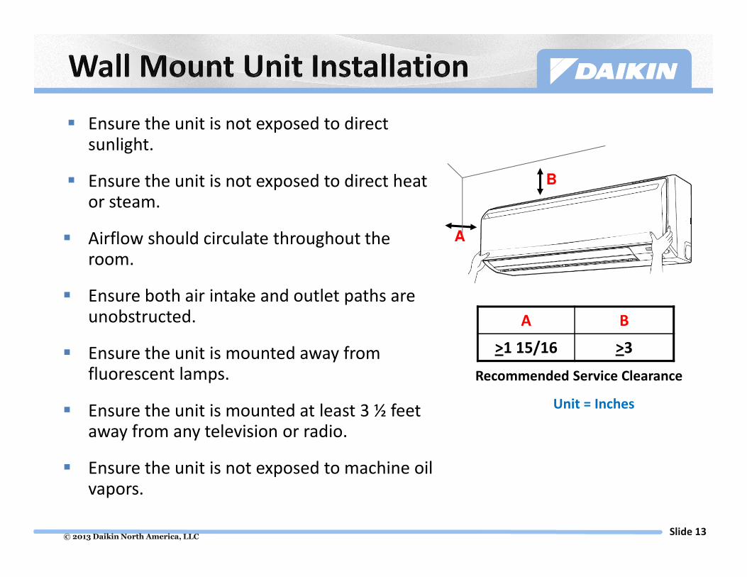
� Ensure the unit is not exposed to direct sunlight.
� Ensure the unit is not exposed to direct heat or steam.
� Airflow should circulate throughout the room.
� Ensure both air intake and outlet paths are unobstructed.
� Ensure the unit is mounted away from fluorescent lamps.
� Ensure the unit is mounted at least 3 ½ feet away from any television or radio.
� Ensure the unit is not exposed to machine oil vapors.
A B
>1 15/16 >3
Unit = Inches
Recommended Service Clearance
B
A

© 2013 Daikin North America, LLCSlide 14
Control Box
> 12”
> 13/16”
> 100”
7-7/8” 9-1/2”
If no ceilingis present
Control BoxSupply Air
Supply Air
Available External Static Pressure from 0.04” to 0.12” wg.

© 2013 Daikin North America, LLCSlide 15
The slim duct unit can be field configured for rear or bottom return
The slim duct unit must be wrapped with an additional 1” thickness of
glass, wool, or polyethylene foam insulation whenever installation
conditions can exceed 86 °F and 80% RH

© 2013 Daikin North America, LLCSlide 16
Sleeve thru wall
Square
to
Round
Grill
FDXS FDXS
� Rear or bottom return
� Requires less than 12” of height clearance
� Install in fur-down/soffit or attic space
� Apply field supplied round or rect. adapters
� Flexible application for Ducted or Duct-Free installations
Oversized return air grill
For return and service
access
FDXS
Round Duct Adapter
2 to 3 outlets

© 2013 Daikin North America, LLCSlide 17
� Slim duct indoor units use a remote mounted
thermistor/wireless receiver.
� Wall mount indoor units use a return air thermistor
located under the front cover.
� The wireless and the BRC944 wired control do not have a
thermistor in them.
� Dead bands for modes of operation (wireless & BRC944)
� Heating has a +3.6°F
� Cooling has a +0°F
� Auto Mode has a +4.5°F / Ducted unit has a +5.4°F
� These values are used to compensate for location
(height) of indoor unit, these dead bands are non-
adjustable.
� The ENVi controls the indoor unit using its own sensor.

© 2013 Daikin North America, LLCSlide 18
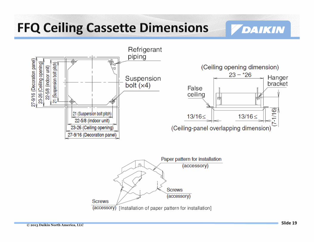
27 9/16”
22 5/8”
> 60”
> 60”
> 60”
> 60”
Obstruction100” For High Ceiling
Installations
≥ 60”
11 1/4
≥ 60”≥ 60”
© 2013 Daikin North America, LLCSlide 19

© 2013 Daikin North America, LLCSlide 20
FFQ Decoration Panel Installation
If a gap exists between the ceiling and the decoration panel after screwing
in the screws, readjust the indoor unit body height to close gap.

© 2013 Daikin North America, LLCSlide 21
Refrigerant Piping

© 2013 Daikin North America, LLCSlide 22
Vertical Separation Rules apply if indoor
units are above OR below condenser
Piping and Wiring can follow same chase
Flare connections at outdoor unit
and at indoor unit
Outdoor Unit Length Vertical Separation Maximum Pipe to
each Indoor Unit
09/12 KE & LV 66 ft. 49 ft. N/A
15/18/24 KE & LV 98 ft. 66 ft. N/A
RXG 32 ft. 26 ft. N/A
2-Port 164 ft. 49 ft. 82 ft.
3-Port & 4-Port 231 ft. 49 ft. 82 ft.
� Minimum 5 linear ft. KE & LV Series
� Minimum 10 linear ft. per line 2-
Port, 3-Port, & 4-Port
� Maximum 24 ft. vertical separation
of indoor units 2-Port, 3-Port, & 4-
Port

© 2013 Daikin North America, LLCSlide 23
Proper deburring is critical to a successful flare

© 2013 Daikin North America, LLCSlide 24
“B” depth for all other sizes
DACA-FSG-1
A
Dimension “B” Requirement
Pipe Size Dimension
1/4” 1 mm
3/8” 2 mm
1/2” 2 mm
5/8” 2 mm
3/4” 2 mm
B
Flaring
Block
Dimension “A” requirement
Pipe Size Dimension
1/4” 9.1mm
3/8” 13.2mm
1/2” 16.6mm
5/8” 19.7mm
3/4” 24.0mm
Go / No Go
“B” depth for ¼”
pipe

© 2013 Daikin North America, LLCSlide 25
� When using the reducer fittings shown above, be careful not to
over tighten the nut, or the smaller pipe may be damaged (about
2/3-1 the normal torque)
� Apply a coat of refrigeration oil to the threaded connection port
of the outdoor unit where the flare nut comes in
� Use an appropriate wrench with backup wrench to avoid
damaging the connection thread by over tightening the flare nut

© 2013 Daikin North America, LLCSlide 26
5/8” to 3/8” or 1/2”
© 2013 Daikin North America, LLCSlide 27
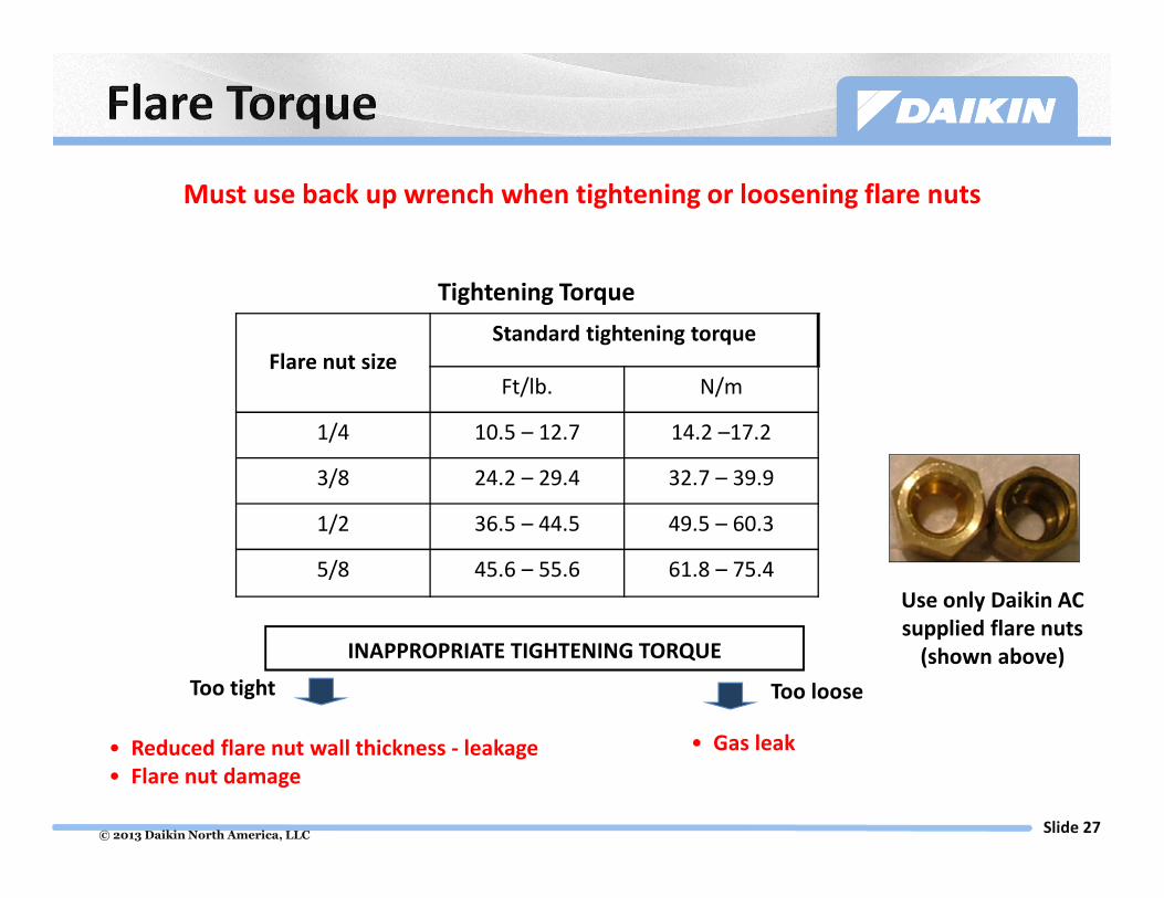
Flare nut size
Standard tightening torque
Ft/lb. N/m
1/4 10.5 – 12.7 14.2 –17.2
3/8 24.2 – 29.4 32.7 – 39.9
1/2 36.5 – 44.5 49.5 – 60.3
5/8 45.6 – 55.6 61.8 – 75.4
Tightening Torque
INAPPROPRIATE TIGHTENING TORQUE
• Reduced flare nut wall thickness - leakage
• Flare nut damage
• Gas leak
Too tight Too loose
Use only Daikin AC
supplied flare nuts
(shown above)
Must use back up wrench when tightening or loosening flare nuts

© 2013 Daikin North America, LLCSlide 28
� Tape in Schrader Fitting
� Set Nitrogen regulator to
1.5 – 3 PSIG
� Leave other end of pipe
open
Dry Nitrogen MUST be used during all brazing
(Pressure regulated to 1.5 to 3 PSIG) to prevent
oxidation formation

© 2013 Daikin North America, LLCSlide 29
10
0
20
30
40
3 min 5 min 24 hours
Step 1 Leak check 3 min. at 150 PSIG
Step 2Leak check after 5 min.
at 325 PSIG
Step 3b
Tighten Down Stop Valves Before Pressure Test
If Stop Valves are not
tightened down prior to
pressure test Nitrogen may
leak back through into
condenser and contaminate
refrigerant.
Step 3aLeak check after 24 h.
at 450 PSIG
NOTE: If FXTQ_PAVJU or
FTQ_PAVJU is installed in
system
NOTE: If no FXTQ_PAVJU or
FTQ_PAVJU is installed in
system. FTQ_PBVJU can be leak
checked at 550 PSIG.
Leak check after 24 h.
at 550 PSIG
50
Pre
ssure
X 1
0
Time
© 2013 Daikin North America, LLCSlide 30
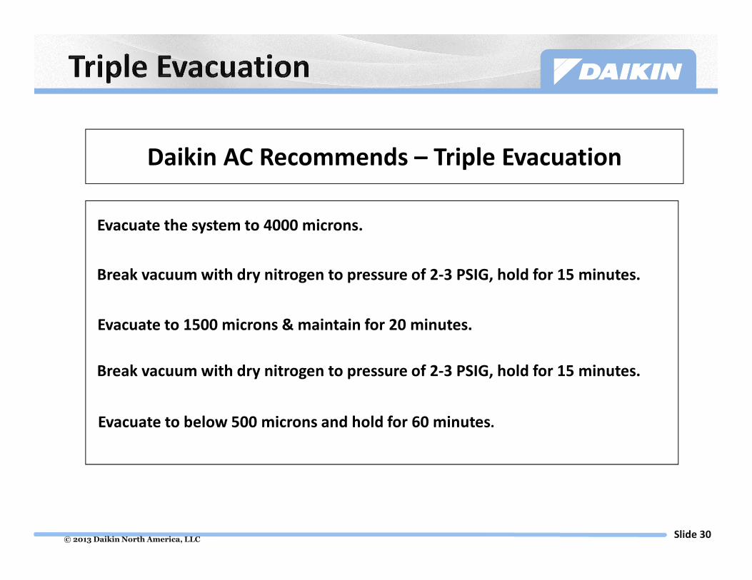
Daikin AC Recommends – Triple Evacuation
Evacuate the system to 4000 microns.
Break vacuum with dry nitrogen to pressure of 2-3 PSIG, hold for 15 minutes.
Evacuate to 1500 microns & maintain for 20 minutes.
Break vacuum with dry nitrogen to pressure of 2-3 PSIG, hold for 15 minutes.
Evacuate to below 500 microns and hold for 60 minutes.

© 2013 Daikin North America, LLCSlide 31
Only install driers, oil traps, shut off valves or any other line components in
your piping work if instructed to do so in the IOM documents – if no
instruction, it’s because it is NOT necessary (for Daikin).
The ONLY acceptable piping is ACR – type (known as refrigeration or
dehydrated copper)

© 2013 Daikin North America, LLCSlide 32
R-410A & PVE Oil

© 2013 Daikin North America, LLCSlide 33
� Asphyxia
� Heavier than air
� Products of Decomposition
� Skin Irritant
� Frostbite
� Safe Exposure
� Storage below 125 F
� Do not leak test with air
2
1
0
NFPA 7041
1
1
HMIS®
ASHRAE
© 2013 Daikin North America, LLCSlide 34
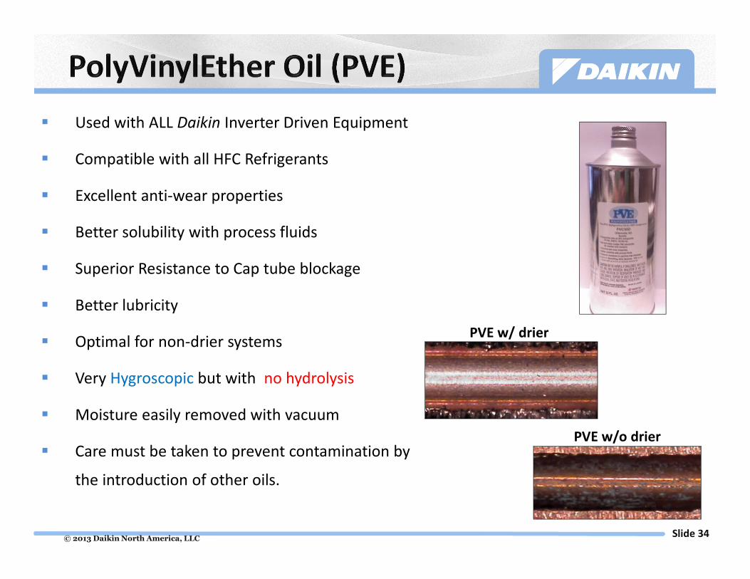
� Used with ALL Daikin Inverter Driven Equipment
� Compatible with all HFC Refrigerants
� Excellent anti-wear properties
� Better solubility with process fluids
� Superior Resistance to Cap tube blockage
� Better lubricity
� Optimal for non-drier systems
� Very Hygroscopic but with no hydrolysis
� Moisture easily removed with vacuum
� Care must be taken to prevent contamination by
the introduction of other oils.
PVE w/ drier
PVE w/o drier
© 2013 Daikin North America, LLCSlide 35
Refrigerant Charging

© 2013 Daikin North America, LLCSlide 36
RXN/RKN_KE Factory ChargeIf line Set Exceeds
33 Feet Add
9,000 Btu 1lb. 12 oz .22 oz per foot
12,000 Btu 2lb. 3.2 oz .22 oz per foot
15,000 Btu 3lb. 12 oz .22 oz per foot
18,000 Btu 3lb. 12 oz .22 oz per foot
24,000 BTU 3lb. 12 oz .22 oz per foot
Outdoor Unit Model No.If line Set Exceeds
98 Feet Add
2MXS18GVJU 5lb. 12 oz .22 oz per foot
Outdoor Unit Model No. Factory ChargeIf line Set Exceeds
131.5 Feet Add
3MXS24 & 4MXS32GVJU 6lb. 13 oz .22 oz per foot
R-410A
� The best time to add refrigerant charge is
immediately after evacuation is complete
� Close vacuum pump valve first, then close
manifold gauges
� R-410A must be charged as a liquid and
weighed in
NOTE: RXS_LV - .21 oz per foot
RXG – No additional charge allowed
© 2013 Daikin North America, LLCSlide 37
Electrical Wiring
© 2013 Daikin North America, LLCSlide 38
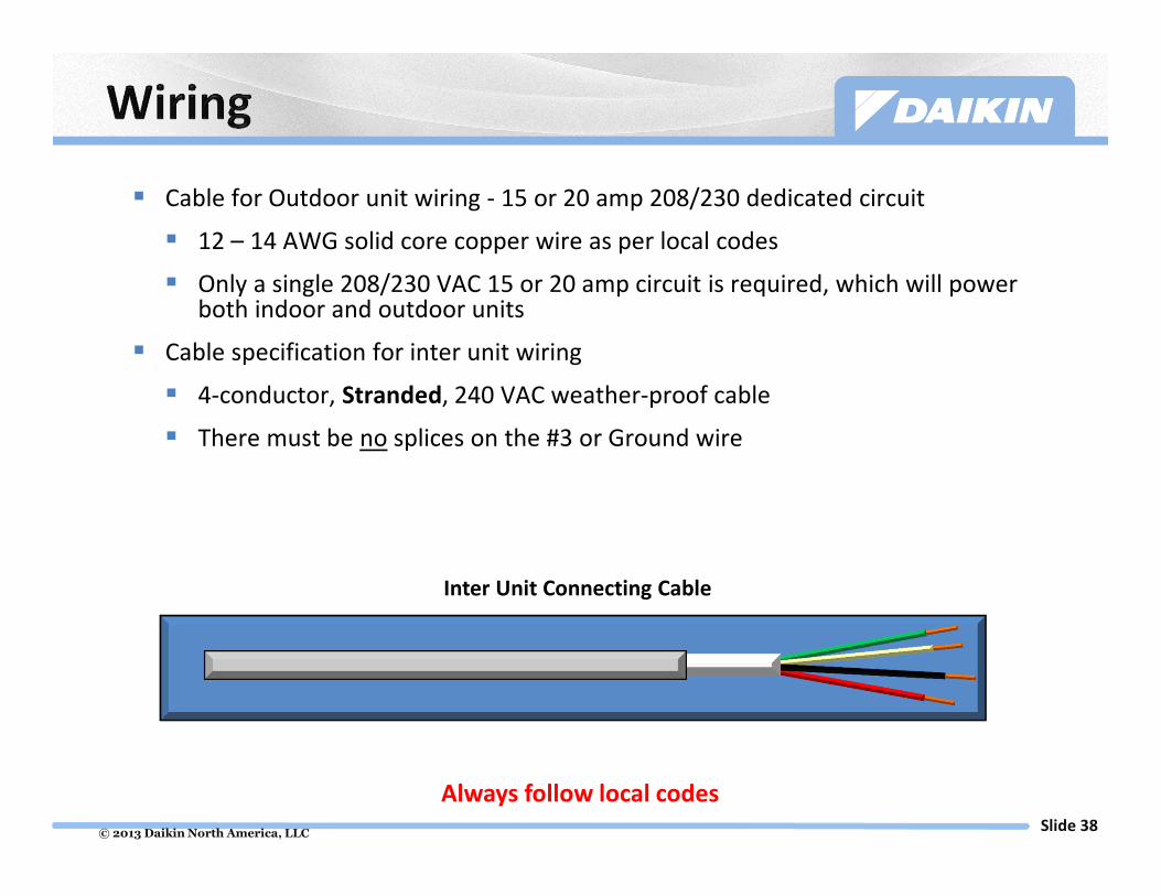
� Cable for Outdoor unit wiring - 15 or 20 amp 208/230 dedicated circuit
� 12 – 14 AWG solid core copper wire as per local codes
� Only a single 208/230 VAC 15 or 20 amp circuit is required, which will power both indoor and outdoor units
� Cable specification for inter unit wiring
� 4-conductor, Stranded, 240 VAC weather-proof cable
� There must be no splices on the #3 or Ground wire
Inter Unit Connecting Cable
Always follow local codes
© 2013 Daikin North America, LLCSlide 39
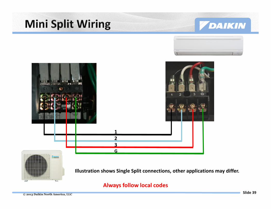
1
2
3G
Illustration shows Single Split connections, other applications may differ.
Always follow local codes

© 2013 Daikin North America, LLCSlide 40
Power indicator LED
A, B, C, & D Terminal block to indoor units
Incoming power terminal block
Priority
dip
switches
Illustration shows 4-Port connections, other applications may differ.
Always follow local codes

© 2013 Daikin North America, LLCSlide 41
� 208/230 VAC is connected to the outdoor unit on L1 L2 and Ground
� Lines 1, 2, 3 + Ground (4 conductor) are connected from the outdoor
unit to each indoor unit
Single 20 amp circuit to power outdoor and all indoor units
Illustration shows 4-Port connections, other applications may differ.
208/230V 1Ph POWER SUPPLY
1 = LINE
2 = LINE
3 = COMM
= Ground
L1 L2 Gnd
1
2
3
1
2
3
1
2
3
1
2
3
1
2
3
1
2
3
1
2
3
1
2
3
Always follow local codes

© 2013 Daikin North America, LLCSlide 42
Condensate Piping Requirements
© 2013 Daikin North America, LLCSlide 43
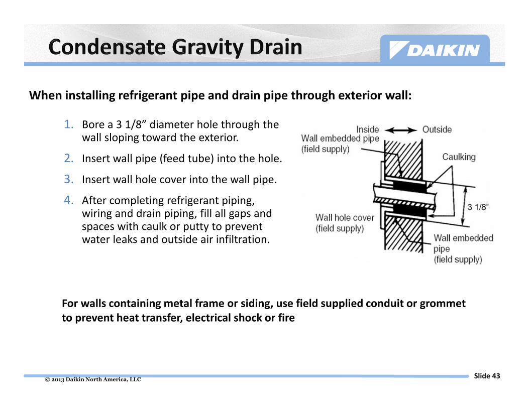
When installing refrigerant pipe and drain pipe through exterior wall:
1. Bore a 3 1/8” diameter hole through the wall sloping toward the exterior.
2. Insert wall pipe (feed tube) into the hole.
3. Insert wall hole cover into the wall pipe.
4. After completing refrigerant piping, wiring and drain piping, fill all gaps and spaces with caulk or putty to prevent water leaks and outside air infiltration.
For walls containing metal frame or siding, use field supplied conduit or grommet
to prevent heat transfer, electrical shock or fire

© 2013 Daikin North America, LLCSlide 44
> 1/100*
* Slope > 1/100 (Rise/Run)
No Traps
� Must not contain any traps
or kinks in the line.
� Must maintain an even slope
of 1/100 or greater.
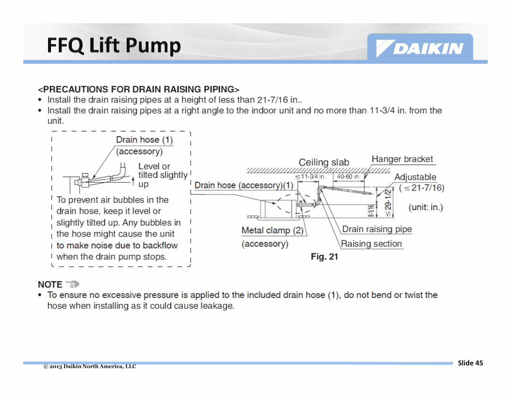
© 2013 Daikin North America, LLCSlide 45
© 2013 Daikin North America, LLCSlide 46
Condensate Accessory Installation

© 2013 Daikin North America, LLCSlide 47
� Installing a condensate pump behind a wall mount unit requires
special consideration due to the limited amount of space left over
after running the line set and line voltage behind the unit.
� If line set has to go out the left hand side of unit, follow the same
instructions listed within for the right hand exit. Drain tubing lengths
may very depending on materials used for line set, high voltage and
drain. Cut lengths of tubing as you assemble drain and line set.
� When exiting on left side use one piece of ½” wall Armaflex insulation
to cover both the liquid and suction lines behind unit. This will give
you more room for the pump and float assembly. After you exit unit
increase insulation back to ¾” wall and insulate the liquid and suction
lines separately.
� After install, prime pump before starting unit. The pump will make a
buzzing sound before it is primed with water. This is normal.
Before You Start Installing Condensate Pump

© 2013 Daikin North America, LLCSlide 48
Drain Hose from Indoor Unit
Pump
KitDrain Hose
from
kit
FittingPump Assembly
Vent Hose
Drain Tubing
© 2013 Daikin North America, LLCSlide 49
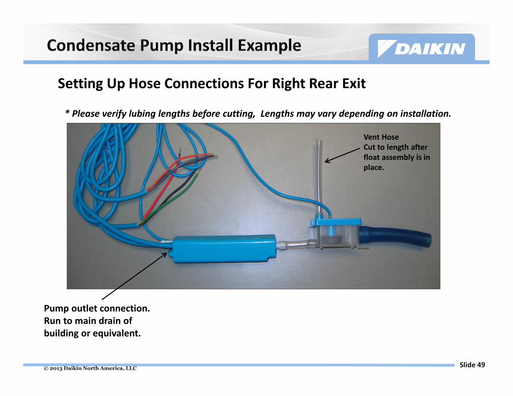
Vent Hose
Cut to length after
float assembly is in
place.
Setting Up Hose Connections For Right Rear Exit
Pump outlet connection.
Run to main drain of
building or equivalent.
* Please verify lubing lengths before cutting, Lengths may vary depending on installation.

© 2013 Daikin North America, LLCSlide 50
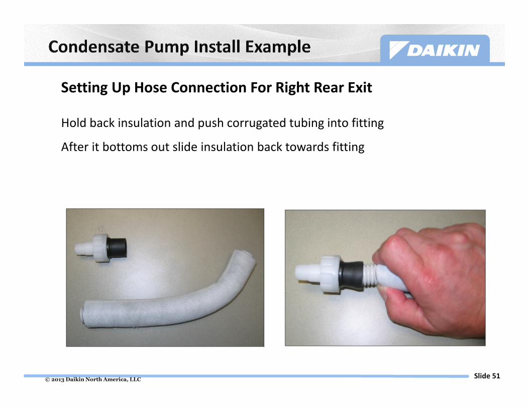
Setting Up Hose Connection For Right Rear Exit
Drain Hose from Indoor Unit
This end always connects to unit.
* Please verify lubing lengths before cutting, Lengths may vary depending on installation.
© 2013 Daikin North America, LLCSlide 51
Hold back insulation and push corrugated tubing into fitting
After it bottoms out slide insulation back towards fitting
Setting Up Hose Connection For Right Rear Exit
© 2013 Daikin North America, LLCSlide 52
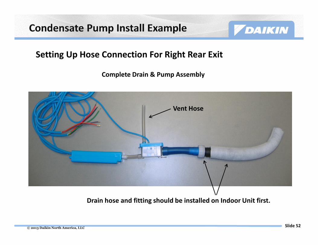
Vent Hose
Complete Drain & Pump Assembly
Drain hose and fitting should be installed on Indoor Unit first.
Setting Up Hose Connection For Right Rear Exit

© 2013 Daikin North America, LLCSlide 53
Right Hand Exit FTXS 18/24 Class, View from Back.
Setting Up Hose Connection For Right Rear Exit
© 2013 Daikin North America, LLCSlide 54
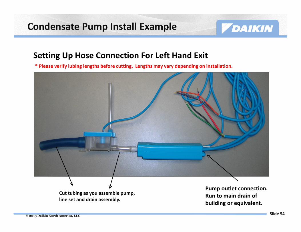
Cut tubing as you assemble pump,
line set and drain assembly.
Pump outlet connection.
Run to main drain of
building or equivalent.
* Please verify lubing lengths before cutting, Lengths may vary depending on installation.
Setting Up Hose Connection For Left Hand Exit

© 2013 Daikin North America, LLCSlide 55
CTXS, FTXS, CDXS & FDXS Wiring
� Very Important
� Do not disturb the # 2 or #3
Communication wire
� Do not disturb the #4 Ground wire
� Run wires all together
� These 3 wires need to run terminal to
terminal (condenser to evaporator).
Normally closed
wire from pump
safety circuit
Power wires for pump
Wire Nuts
Outdoor Unit
Terminals
Aspen Pump
DACA-CP1-1
1 amp in line fuse
(comes with pump)
Cap normally open
wire from pump
safety circuit
208-230 VAC
1PH Indoor Unit
Terminals

© 2013 Daikin North America, LLCSlide 56
� FTXS/CTXS/ FTXN/FTXG Wallmount Units
� Condensate overflow protection for all Daikin
wallmount fan coil units
� Microelectronic control
� No moving parts
� Simple two component installation
� Drain Pan Water Sensor
� Electronic Control Switch
Drain Pan Water Sensor
Electronic Control Switch
Line Voltage Powered
DACA- CFS1

© 2013 Daikin North America, LLCSlide 57
� For installation, Daikin AC
recommends mounting the
sensor on the right hand corner
of the heat exchanger as facing
the front of the fan coil and
where the electrical box will be
to the right of the fan coil.
� Once mounted at the
appropriate height, Daikin AC
recommends wiring the sensor
assembly for mini split wall
mounted units (FTXN, FTXS,
FTXG, & CTXS models) as shown
to the right
� Refer to the float switch
installation manual for all other
installation instructions
© 2013 Daikin North America, LLCSlide 58
Controls

© 2013 Daikin North America, LLCSlide 59
2 3 G
Black RedGreen
TERMINAL BLOCK
DPCA
P2
P1
S21
MAIN PCB
Daikin Indoor Unit
Incoming
208/230V 1
Field Supplied 4 core
thermostat wire
18AWGWire Harness (5’ 4”)
come within a box
Power Cable (5’ 4”)
from DPCA
208/230VAC
DPCA can be installed in the backside cavity of the wall-mounted
indoor unit (if space allows) and beside the ducted indoor unit.
DPCA should not be installed in plenum.
Wires to
outdoor unit
not shown
To ENVi : 2-wires for power supply 24VAC
2-wires for communication
ENVi Thermostat
Cannot be used with FFQ Indoor Unit
FTXN09/12KE requires KRP9801B

© 2013 Daikin North America, LLCSlide 60
D-, D+ : 2 wire for RS485 serial
communication (Modbus)
C, R : 2 wire for power supply (24VAC)

© 2013 Daikin North America, LLCSlide 61
Installation – FTXN/FTXS/CTXS/FDXS/CDXS
FTXN09/12KE requires KRP980B1 – see slide 102

© 2013 Daikin North America, LLCSlide 62
P1 P2
BRC1E72 Navigation Remote for FFQ ONLY

© 2013 Daikin North America, LLCSlide 63
Field Settings
© 2013 Daikin North America, LLCSlide 64
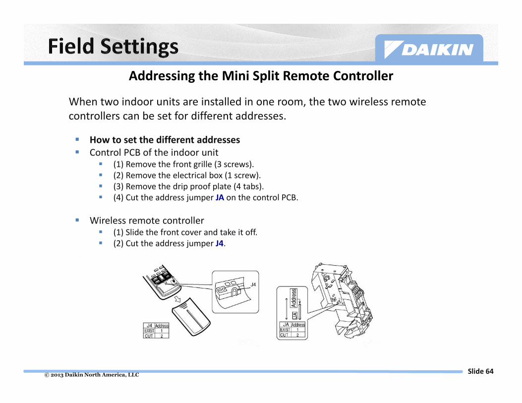
Addressing the Mini Split Remote Controller
When two indoor units are installed in one room, the two wireless remote
controllers can be set for different addresses.
� How to set the different addresses
� Control PCB of the indoor unit� (1) Remove the front grille (3 screws).
� (2) Remove the electrical box (1 screw).
� (3) Remove the drip proof plate (4 tabs).
� (4) Cut the address jumper JA on the control PCB.
� Wireless remote controller� (1) Slide the front cover and take it off.
� (2) Cut the address jumper J4.

© 2013 Daikin North America, LLCSlide 65
With the 2,3 & 4-Port systems, one of the indoor fan coils must dictate the system mode of operation, for heat or cool. Daikin provides two options to determine the Priority fan coil:
Option 1 (Recommended)
At the time of system commissioning,
one fan coil is configured as the
Master from the Outdoor Unit.
Option 2
If a priority indoor fan coil is not selected from the Outdoor
Unit, the first indoor unit switched ON becomes the temporary
Master. When this indoor unit is switched OFF, the next indoor
unit which has had an opposite active call for the longest period
of time is made the next temporary Master. Therefore, the
“floating” priority fan coil function is adopted.
Setting Priority

© 2013 Daikin North America, LLCSlide 66
� You should choose a Priority Unit during install.
� For 2-Port Multi. Inside outdoor unit on PCB slide A or B dip switch over opposite others.
� For a 3 or 4-Port Multi. Inside outdoor unit on PCB slide A, B, C or D dip switch over opposite others.
� This must be done with power off.
Multi 2, 3, & 4-Port Priority Set Up

© 2013 Daikin North America, LLCSlide 67
Night Quiet Mode Activation
Multi Split 2, 3, & 4-Port
Outdoor Unit
SW5 Night Quiet Mode Switch

© 2013 Daikin North America, LLCSlide 68
Cutting jumper (J3) on the PCB, as shown below, will expand the operation range down
to 14°F (–10°C). If the outdoor temperature drops below –4°F (–20°C), the operation
stops and starts back up once the temperature rises again.
1. Remove the 3 screws on the side and remove the top plate of the outdoor unit.
2. Remove the drip proof cover.
3. Cut the jumper (J3).
Disconnect power from outdoor unit, then wait 10 minutes before cutting jumper
RKN_KEVJU/RXN_KEVJU Low Ambient Cooling
This function is designed for facilities such as equipment or computer rooms.
It is never to be used in a residence or office where people occupy the space.
© 2013 Daikin North America, LLCSlide 69
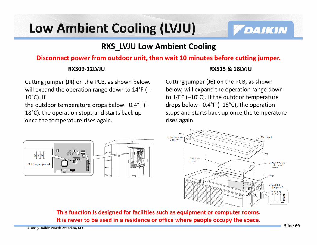
Cutting jumper (J6) on the PCB, as shown
below, will expand the operation range down
to 14°F (–10°C). If the outdoor temperature
drops below –0.4°F (–18°C), the operation
stops and starts back up once the temperature
rises again.
1. Remove the 3 screws on the side and
remove the top plate of the outdoor unit.
2. Remove the drip proof cover.
3. Cut the jumper (J6).
Cutting jumper (J4) on the PCB, as shown below,
will expand the operation range down to 14°F (–
10°C). If
the outdoor temperature drops below –0.4°F (–
18°C), the operation stops and starts back up
once the temperature rises again.
RXS09-12LVJU RXS15 & 18LVJU
This function is designed for facilities such as equipment or computer rooms.
It is never to be used in a residence or office where people occupy the space.
RXS_LVJU Low Ambient Cooling
Disconnect power from outdoor unit, then wait 10 minutes before cutting jumper.

© 2013 Daikin North America, LLCSlide 70
Turning on Switch B will expand the operation range down to 14°F (–10°C). If the
outdoor temperature drops below –0.4°F (–18°C), the operation stops and starts back up
once the temperature rises again.
RKS30/36LVJU & RXS24/30/36LVJU Low Ambient Cooling
This function is designed for facilities such as equipment or computer rooms.
It is never to be used in a residence or office where people occupy the space.
Year-Round Cooling kits available, 2F018535-1 & 2F018535-2, allow low ambient cooling to -40°F

© 2013 Daikin North America, LLCSlide 71
Start Up

© 2013 Daikin North America, LLCSlide 72
� Indoor and outdoor units are installed securely & are level.
� Pressure test system to 550 PSIG for 24 hours.
� Perform triple evacuation on system.
� Break with nitrogen, to 500 microns.
� Calculate liquid line length and corresponding required additional
refrigerant charge.
� Weigh in additional charge to liquid line.
� Open service valves.
� Check supply voltage (L1 to L2).
� Must read between 187 and 253 volts.

© 2013 Daikin North America, LLCSlide 73
� Ensure all drain pipe is properly connected.
� Ensure all filters are in place.
� Ensure all refrigerant piping is properly insulated.
� Insulate each line independently.
� Power system on for 6 hours.
� Single Split – Turn on the indoor unit using the remote control and
test each mode of operation
� Multi Split – Turn on each indoor unit individually using the remote
control and test each mode of operation.
NOTE: All modes of operation may not be available depending on the
outside ambient conditions, see the sequence of operation for more
information.
If system does not operation properly, proceed to Troubleshooting

© 2013 Daikin North America, LLCSlide 74
Troubleshooting

© 2013 Daikin North America, LLCSlide 75
If the system does not operate when turned ON, use the following steps to test the operation of the
equipment
1. Turn ON the unit and place it in Heating or Cooling mode (depending on season), wait 15 to 20
minutes
2. When the unit is operating without error, the green light on the front of the wall mount unit or
green light on the wired receiver for the ducted unit will remain ON and solid. If there is an error
present, this green light will be ON and blinking.
See slides 78-79 for steps to retrieve active error code from the indoor unit
3. The charts provided on slides 78- 79 give a brief description on each error code. For more
information, consult the Service Manual for the unit your working on. All Daikin manuals can be
found at www.daikinac.com
4. Multi Split system only – Troubleshooting is available from the outdoor unit PCB.
See slide 80 for steps to retrieve active error code from the outdoor unit
5. If green light is ON and solid, try running the system through Trial or Test mode. These modes
test operation of the system
See slides 81-90 on how to initiate Trial and Forced Operation modes
6. If more than the above steps are needed, contact your local Rep or Distributor for assistance

© 2013 Daikin North America, LLCSlide 76
CTXS/FTXS09/12LVJU
FTXS09 thru 24LVJU
� The green operation lamp on the indoor unit’s front panel will flash
when:
� A protection device in the indoor or outdoor unit activates
� A thermistor malfunctions
� A signal transmission error occurs
FDXS & CDXS_LVJU

© 2013 Daikin North America, LLCSlide 77
� Press and hold the “Timer Cancel” button (A) for 5 seconds to activate the service check function and a long beep will sound from the indoor unit.
� The temperature display on the remote’s LCD display flashes “00” (B). As you continue to press the Cancel button, error codes will continue to display with a short beep.
� Press the “Timer Cancel” button (A) repeatedly until a long “beep” is heard.
� The temperature display changes from flashing “00” to the last fault code stored in memory (B).
� Press and hold the “Timer Cancel” button (A) for 5 seconds to deactivate the service check function.
� Service check mode will cancel automatically after 1 minute.
A
B
Your remote controller may
look slightly different but same
steps apply.

© 2013 Daikin North America, LLCSlide 78

© 2013 Daikin North America, LLCSlide 79
© 2013 Daikin North America, LLCSlide 80
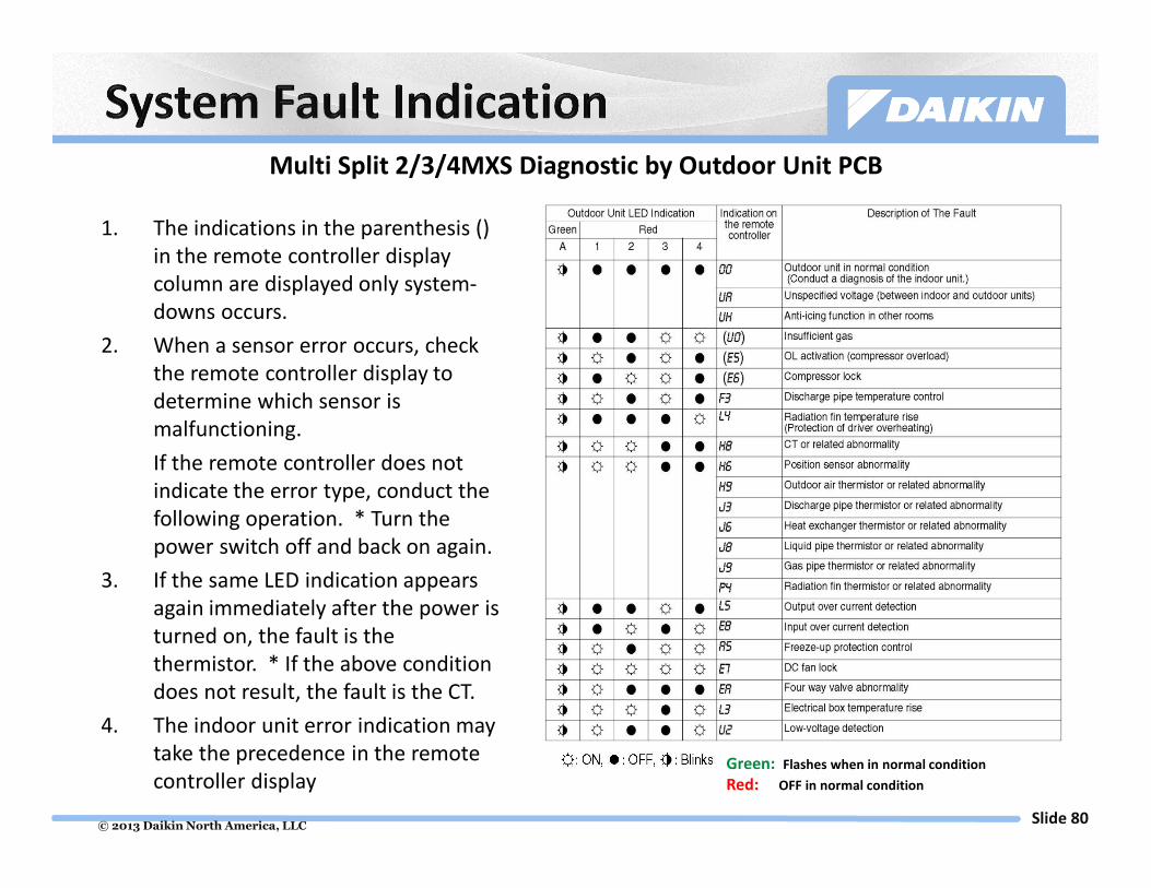
Multi Split 2/3/4MXS Diagnostic by Outdoor Unit PCB
1. The indications in the parenthesis ()
in the remote controller display
column are displayed only system-
downs occurs.
2. When a sensor error occurs, check
the remote controller display to
determine which sensor is
malfunctioning.
If the remote controller does not
indicate the error type, conduct the
following operation. * Turn the
power switch off and back on again.
3. If the same LED indication appears
again immediately after the power is
turned on, the fault is the
thermistor. * If the above condition
does not result, the fault is the CT.
4. The indoor unit error indication may
take the precedence in the remote
controller displayGreen: Flashes when in normal condition
Red: OFF in normal condition

© 2013 Daikin North America, LLCSlide 81
� Trial Operation
� Trial mode is a self diagnostic check
� Forced Operation
� Cooling mode can be forced from the indoor or outdoor unit
(model specific).
� Multi systems additionally can force Heat mode from the outdoor unit.

© 2013 Daikin North America, LLCSlide 82
KEVJU, LVJU & Multi Series

© 2013 Daikin North America, LLCSlide 83
Quaternity Series

© 2013 Daikin North America, LLCSlide 84
Using the indoor unit ON/OFF switch
� Press the indoor unit ON/OFF switch for at least 5 seconds. (Operation will
start)
� Forced cooling operation will stop automatically after around 15
minutes. To force a trial operation to stop, press the indoor unit
ON/OFF switch.
Using the indoor unit’s remote controller
1. Press the ON/OFF button. (Operation will start)
2. Press the TEMP button and the MODE button at the same time.
3. Press the MODE button twice. ( will be displayed and the unit will
enter trial operation)
4. Press the MODE button to return the operation mode to cooling.
� Trial operation will stop automatically after around 30 minutes. To
force a trial operation to stop, press the ON/OFF button.
Indoor Units
FTXN09KEVJU
FTXN12KEVJU
© 2013 Daikin North America, LLCSlide 85
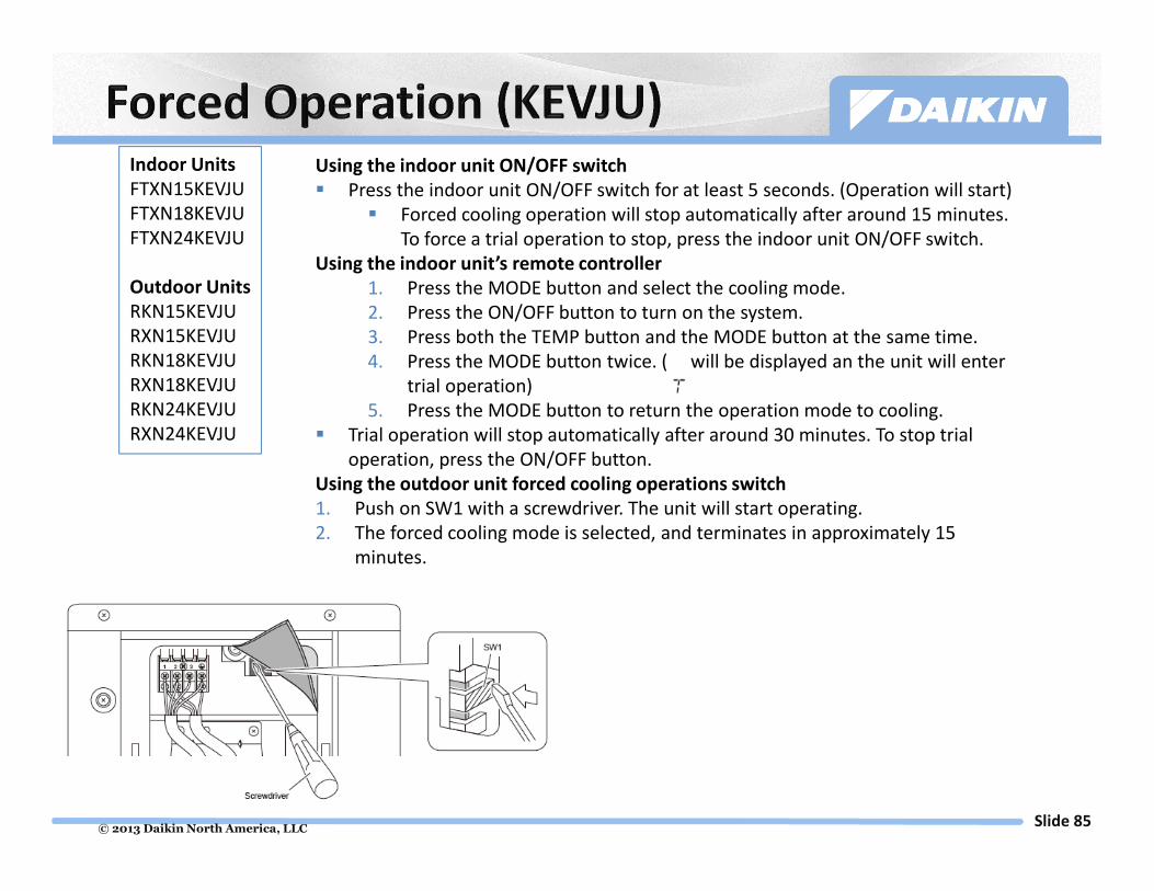
Indoor Units
FTXN15KEVJU
FTXN18KEVJU
FTXN24KEVJU
Outdoor Units
RKN15KEVJU
RXN15KEVJU
RKN18KEVJU
RXN18KEVJU
RKN24KEVJU
RXN24KEVJU
Using the indoor unit ON/OFF switch
� Press the indoor unit ON/OFF switch for at least 5 seconds. (Operation will start)
� Forced cooling operation will stop automatically after around 15 minutes.
To force a trial operation to stop, press the indoor unit ON/OFF switch.
Using the indoor unit’s remote controller
1. Press the MODE button and select the cooling mode.
2. Press the ON/OFF button to turn on the system.
3. Press both the TEMP button and the MODE button at the same time.
4. Press the MODE button twice. ( will be displayed an the unit will enter
trial operation)
5. Press the MODE button to return the operation mode to cooling.
� Trial operation will stop automatically after around 30 minutes. To stop trial
operation, press the ON/OFF button.
Using the outdoor unit forced cooling operations switch
1. Push on SW1 with a screwdriver. The unit will start operating.
2. The forced cooling mode is selected, and terminates in approximately 15
minutes.

© 2013 Daikin North America, LLCSlide 86
Indoor Units
FDXS09LVJU
FDXS12LVJU
FTXS09LVJU
FTXS12LVJU
Outdoor Units
RXS09LVJU
RXS12LVJU
Using the indoor unit’s remote controller
1. Press the MODE button and select the cooling mode.
2. Press the ON/OFF button to turn on the system.
3. Press both the TEMP button and the MODE button at the same time.
4. Press the MODE button twice. ( will be displayed and the unit will enter forced
cooling operation)
5. Press the MODE button to return the operation mode to cooling.
Forced cooling operation will stop automatically after around 30 minutes. To stop the
operation, press the ON/OFF button.
Using the outdoor unit forced cooling operations switch
Forced cooling operation can be performed when the outdoor unit forced cooling
operation switch is pressed within around 3 minutes after power is supplied.
� Push on (SW1) with a screwdriver. The unit will start operating.
� Forced cooling operation will stop automatically after around 15 minutes. To stop
the operation, press the SW1 switch.

© 2013 Daikin North America, LLCSlide 87
Indoor Units
FTXS15LVJU
FTXS18LVJU
Outdoor Units
RXS15LVJU
RXS18LVJU
Using the indoor unit ON/OFF switch
� Press the indoor unit ON/OFF switch for at least 5 seconds. (Operation will start)
� Forced cooling operation will stop automatically after around 15 minutes. To stop
the operation, press the indoor unit ON/OFF switch.
Using the indoor unit’s remote controller
1. Press the MODE button and select the cooling mode.
2. Press the ON/OFF button to turn on the system.
3. Press both the TEMP button and the MODE button at the same time.
4. Press the MODE button twice. ( will be displayed and the unit will enter forced
cooling operation)
Forced cooling operation will stop automatically after around 30 minutes. To stop the
operation, press the ON/OFF button.
Using the outdoor unit forced cooling operations switch
Forced cooling operation can be performed when the outdoor unit forced cooling
operation switch is pressed within around 3 minutes after power is supplied.
� Push on (SW1) with a screwdriver. The operation will start.
� Forced cooling operation will stop automatically after around 15 minutes. To stop
the operation, press the SW1 switch.
© 2013 Daikin North America, LLCSlide 88
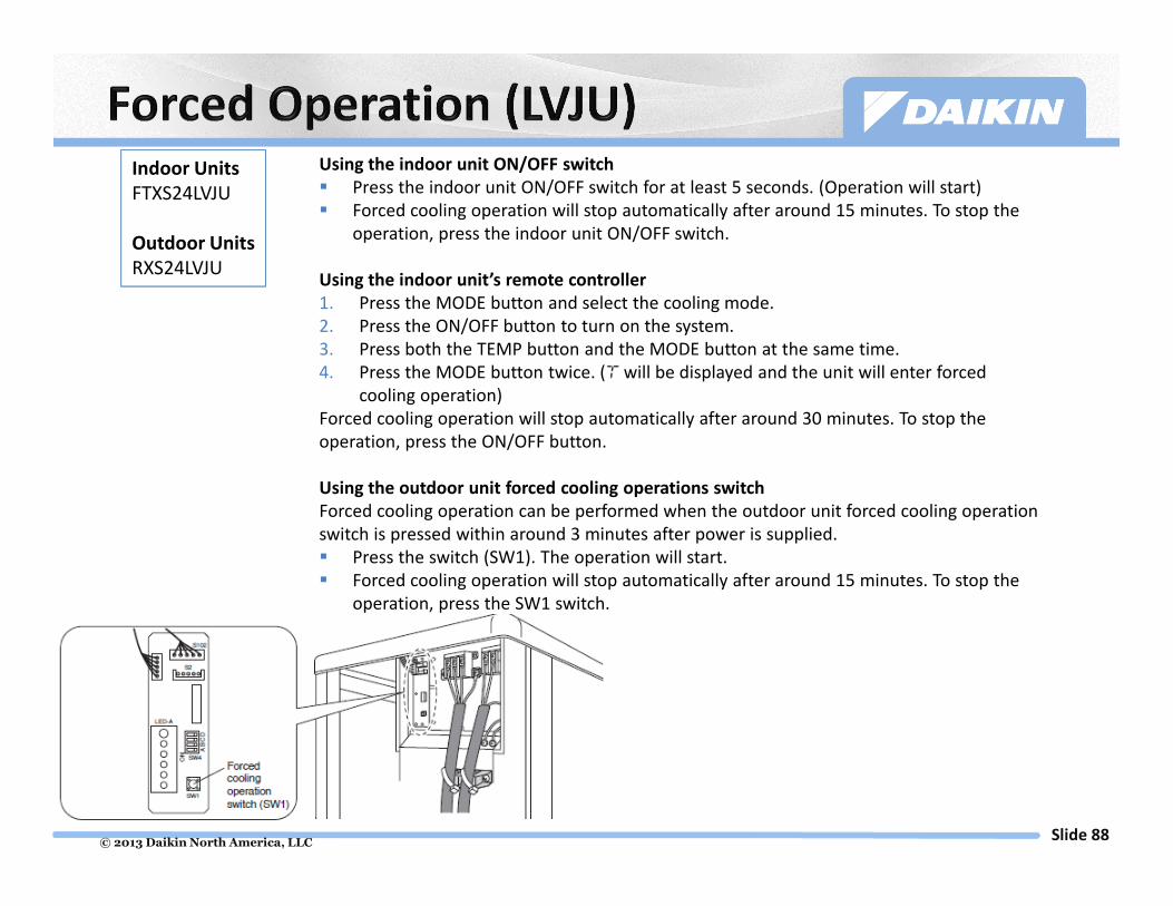
Indoor Units
FTXS24LVJU
Outdoor Units
RXS24LVJU
Using the indoor unit ON/OFF switch
� Press the indoor unit ON/OFF switch for at least 5 seconds. (Operation will start)
� Forced cooling operation will stop automatically after around 15 minutes. To stop the
operation, press the indoor unit ON/OFF switch.
Using the indoor unit’s remote controller
1. Press the MODE button and select the cooling mode.
2. Press the ON/OFF button to turn on the system.
3. Press both the TEMP button and the MODE button at the same time.
4. Press the MODE button twice. ( will be displayed and the unit will enter forced
cooling operation)
Forced cooling operation will stop automatically after around 30 minutes. To stop the
operation, press the ON/OFF button.
Using the outdoor unit forced cooling operations switch
Forced cooling operation can be performed when the outdoor unit forced cooling operation
switch is pressed within around 3 minutes after power is supplied.
� Press the switch (SW1). The operation will start.
� Forced cooling operation will stop automatically after around 15 minutes. To stop the
operation, press the SW1 switch.

© 2013 Daikin North America, LLCSlide 89
SW1
SW2
1. Turn the Operation Mode switch SW2 to “COOL”
2. Press the Forced Operation switch SW1 to begin forced cooling.
Press the Forced Operation switch SW1 again to stop forced cooling
3. Push SW1 to stop or forced Cooling will terminate after 15 minutes
4. Multi Split systems can also test Heating mode, move SW2 to
“HEAT”, then follow steps 2~3
Outdoor Units
2MXS18GVJU
3MXS24GVJU
4MXS32GVJU

© 2013 Daikin North America, LLCSlide 90
Indoor Units
FTXG09HVJU
FTXG12HVJU
FTXG15HVJU

© 2013 Daikin North America, LLCSlide 91
The equipment listed in this presentation all can pump themselves down,
refrigerant will be stored in the outdoor unit.
There are different steps depending on model, see slides 92-93.

© 2013 Daikin North America, LLCSlide 92
LVJU (see slides 86-88 for forced operation)
1. Remove the valve lids from liquid stop valve
and gas stop valve.
2. Carry out forced cooling operation.
3. After five to ten minutes, close the liquid
stop valve with a metric Allen wrench.
4. After two to three minutes more, close the
gas stop valve and stop forced cooling
operation.
KEVJU (see slides 84-85 for forced operation)
Use refrigeration gauges to verify no pressure is present prior to disconnecting any piping.
Allen wrench
Liquid Stop Valve
Gas Stop Valve
Service Port
Valve Lid
Close
1. Remove the valve lids from liquid stop valve
and gas stop valve.
2. Carry out forced cooling operation.
3. After five to ten minutes, close the liquid
stop valve with a metric Allen wrench.
4. After two to three minutes more, close the
gas stop valve and stop forced cooling
operation.

© 2013 Daikin North America, LLCSlide 93
1. Remove the valve lids from both liquid
stop gas stop valve.
2. Carry out forced cooling operation.
3. After five to ten minutes, close liquid
stop valve with a metric Allen wrench.
4. After two to three minutes more, close
gas stop valve and stop forced cooling
operation.
Multi Split 2, 3, & 4-Port Outdoor Unit
(see slide 89 for forced operation)
Use refrigeration gauges to verify no pressure is present prior to disconnecting any piping.
Allen wrench
Liquid Stop Valve
Gas Stop Valve
Service Port
Valve Lid
Close
1. Remove the valve lids from liquid stop
valve and gas stop valve.
2. Carry out forced cooling operation.
3. After five to ten minutes, close the
liquid stop valve with a metric Allen
wrench.
4. After two to three minutes more, close
the gas stop valve and stop forced
cooling operation.
Quaternity (see slide 90 for forced operation)

© 2013 Daikin North America, LLCSlide 94
Accessories

© 2013 Daikin North America, LLCSlide 95
Wall Mount Bracket Kit
DACA-WB-3
Wind Baffle Kits
KPW937C4 (RXS09/12LVJU)
KPW945A4 (RXS15/18/24LVJU)
KPW038A4 (RXS09/12KEVJU)
KPW937C4 (RXS15/18/24KEVJU)
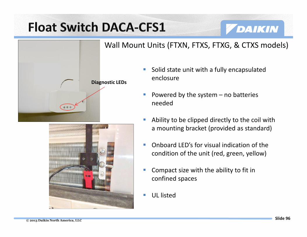
© 2013 Daikin North America, LLCSlide 96
Diagnostic LEDs
� Solid state unit with a fully encapsulated
enclosure
� Powered by the system – no batteries
needed
� Ability to be clipped directly to the coil with
a mounting bracket (provided as standard)
� Onboard LED’s for visual indication of the
condition of the unit (red, green, yellow)
� Compact size with the ability to fit in
confined spaces
� UL listed
Wall Mount Units (FTXN, FTXS, FTXG, & CTXS models)

© 2013 Daikin North America, LLCSlide 97
DACA-CP1-1
© 2013 Daikin North America, LLCSlide 98
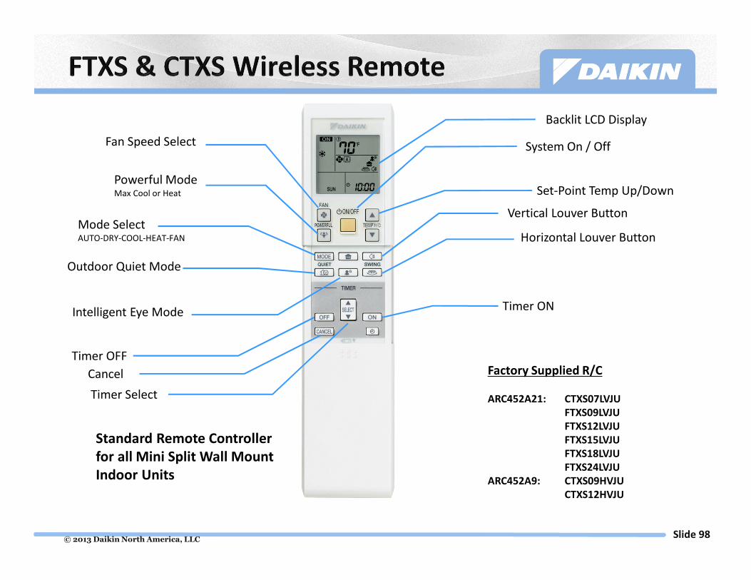
Factory Supplied R/C
ARC452A21: CTXS07LVJU
FTXS09LVJU
FTXS12LVJU
FTXS15LVJU
FTXS18LVJU
FTXS24LVJU
ARC452A9: CTXS09HVJU
CTXS12HVJU
Standard Remote Controller
for all Mini Split Wall Mount
Indoor Units
Fan Speed Select
Powerful ModeMax Cool or Heat
Mode SelectAUTO-DRY-COOL-HEAT-FAN
Outdoor Quiet Mode
Intelligent Eye Mode
Timer Select
Backlit LCD Display
System On / Off
Set-Point Temp Up/Down
Vertical Louver Button
Horizontal Louver Button
Timer ON
Timer OFF
Cancel

© 2013 Daikin North America, LLCSlide 99
If function is active the icon
will appear on screen

© 2013 Daikin North America, LLCSlide 100
� This controller provides the
option of a wall mounted
controller for light commercial
applications
� For use with all Daikin Single and
Multi models*
� Controller can be used in
conjunction with the wireless
remote controller
*Not available for FFQ indoor unit
Controller Features
Start / Stop
Operation Mode
Temperature Setting (18 - 32°C, 64 - 90°F)
One Time / Daily Timer
Fahrenheit or Celsius Temperature Display
Fan Speed
Airflow Direction
System On/Off
Display
Clock Setting
Fan Airflow Select
Set-Point Temp Up/Down
Time Select Up/Down
Operation Light
One Time Daily Timer
Time Set
Swing Mode
(Louvers)
System Mode

© 2013 Daikin North America, LLCSlide 101
Refer to slides 59-60 for wiring information
The Daikin ENVi thermostat kit includes:
Menu
Navigation
Buttons
Back
Color
Touch-Screen
Display
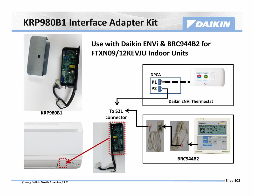
© 2013 Daikin North America, LLCSlide 102
Use with Daikin ENVi & BRC944B2 for
FTXN09/12KEVJU Indoor Units
DPCA
Daikin ENVi Thermostat
P2
P1
BRC944B2
To S21
connectorKRP980B1

© 2013 Daikin North America, LLCSlide 103
System
On/Off
Backlit Display
Cancel
Navigation
Buttons
Fan Speed
System Mode
� Large Backlit LCD Display
� Display configurable to Detailed,
Standard, and Simple
� Room temperature display – Day and
Time
� Selectable display languages & °F or °C
Temp
� Automatic Changeover Heat Pump &
Heat Recovery
� Weekly Schedule
� Dual and Single Cool & Heat setpoints
� Independent Setback Setpoints
� Selectable 12/24 hour clock display
� Auto-adjustable Daylight Savings Time
(DST)
� Max. 16 connectable indoor units
� Optional Face Decals to hide
unnecessary or locked out buttons

© 2013 Daikin North America, LLCSlide 104
Model Name Description Applicable to
DACA-ARCW901P10 IR Receiver Cable, Plenum Rated, 10ft FDXS09,12DVJU
DACA-ARCW901P25 IR Receiver Cable, Plenum Rated, 25ft FDXS09,12DVJU
DACA-BRCW901P10 Remote Controller Cable, Plenum Rated, 10ft BRC944B2-A08
DACA-BRCW901P25 Remote Controller Cable, Plenum Rated, 25ft BRC944B2-A08

© 2013 Daikin North America, LLCSlide 105
Simple installation to interface mini split 4-wire communication
to VRV D-III Net 2-wire F1 F2
KRP928B
F1 F2 Out Circuit
1 2 3 Gnd
Intelligent Touch
Controller

© 2013 Daikin North America, LLCSlide 106
Bottom Plate Heater Kits offer an option for extraordinary applications where a
large number of heating operating hours are seen between 17°F and 32°F coupled
with large amounts of snowfall.

© 2013 Daikin North America, LLCSlide 107
• Proper Equipment Selection
• Equipment Location Considerations
• Refrigerant Piping
• R-410A & PVE Oil
• Refrigerant Charging
• Electrical Wiring
• Condensate Piping Requirements
• Controls
• Field Settings
• Start Up
• Basic Troubleshooting
• Accessories

© 2013 Daikin North America, LLCSlide 108
Thank You