Embed Size (px)
Citation preview

Great Company Great PeopleGreat Company Great People 11
Key Issues of 3GPP LTE-Advanced
June 21th, 2010
Sungho Moon
4G Technical Research Gr. MCTRL

Great Company Great PeopleGreat Company Great People
Contents
3GPP standard history and activity
Key issues in LTE-Advanced (especially for release-10 time frame)• Carrier aggregation
• Relay
• DL MIMO enhancement
• UL MIMO enhancement
References
2

Great Company Great PeopleGreat Company Great People 33
3GPP Standard History and Activity
Great Company Great People
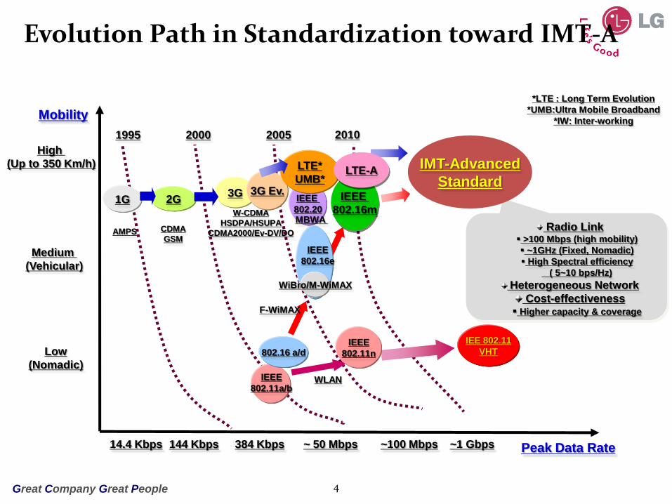
Evolution Path in Standardization toward IMT-A
4
*LTE : Long Term Evolution
*UMB:Ultra Mobile Broadband
*IW: Inter-working
1G 2G
High
(Up to 350 Km/h)
Medium
(Vehicular)
Low
(Nomadic)
Peak Data Rate14.4 Kbps 144 Kbps 384 Kbps ~ 50 Mbps ~100 Mbps
CDMA
GSMAMPS
W-CDMA
HSDPA/HSUPA
CDMA2000/Ev-DV/DO
1995 2000 2005 2010
WiBro/M-WiMAX
IEEE
802.16e
IEEE
802.11a/b
802.16 a/d
Mobility
3G
IEEE
802.11n
Radio Link >100 Mbps (high mobility)
~1GHz (Fixed, Nomadic)
High Spectral efficiency
( 5~10 bps/Hz)
Heterogeneous Network
Cost-effectiveness Higher capacity & coverage
IMT-Advanced
Standard
~1 Gbps
3G Ev.IEEE
802.20
LTE*
UMB*
WLAN
F-WiMAX
MBWA
IEE 802.11
VHT
IEEE
802.16m
LTE-A

Great Company Great People
3GPP – the Partnership
3GPP stands for 3rd Generation Partnership Project*.
The partners are standards developing organizations:
Contribution driven … companies participate in 3GPP through their membership of one of these “Organizational partners”
Currently over 350 individual members (Operators, Vendors, Regulators)
13 Market representation partners (giving perspectives on market needs and drivers)
5
* 3GPP is not constrained to 3rd Generation. It includes work on both 2nd and 4th generation technologies.

Great Company Great People
3GPP – the Work
Approximately 185 meetings per year
Many co-located meetings, totaling around 600 delegates
Some meetings receive 1000 documents
6

Great Company Great People
Release of 3GPP Specification
7
1999 2000 2001 2002 2003 2004 2005
Release 99
Release 4
Release 5
Release 6
1.28Mcps TDD
HSDPA, IMS
W-CDMA
HSUPA, MBMS, IMS+
2006 2007 2008 2009
Release 7 HSPA+ (MIMO, HOM etc.)
Release 8
2010 2011
LTE, SAEITU-R M.1457
IMT-2000 Recommendations
Release 9
LTE-AdvancedRelease 10
GSM/GPRS/EDGE enhancements
Small LTE/SAE enhancements

Great Company Great People
Timelines for LTE-Advanced
LTE-Advanced
“3GPP submission for the ITU’s IMT-Advanced system”
8
Key Timeline for LTE-A Date
Study Item, “LTE-Advanced” approved in 3GPP Mar. 2008
LTE-Advanced Requirements (TR. 36.913) Jun. 2008
LTE-Advanced “Early Submission” made to ITU-R Sep. 2008
“Complete Technology Submission” to ITU-R Jun. 2009
“Final Submission” to ITU-R Oct. 2009
Completion of LTE-Advanced specification by 3GPP 2010/2011

Great Company Great People
System Requirements of LTE-A
Requirement 3GPP LTE-A 3GPP LTE
C-Plane Latency (Dormant <-> Active)
Less than 10 ms Less than 50 ms
C-Plane Latency (Idle <-> Active)
50 ms 100 ms
U-Plane Latency Less than Rel-8 Less than 5 ms
Peak Data Rate DL: 30bps, UL: 15bps DL: 5bps, UL: 2.5bps
Average Spectrum Efficiency
DL: 2.4(2x2),2.6(4x2),3.7(4x4)UL: 1.2(1x2),2.0(2x4)
DL: 3~4 times of Rel6 HSDPA (2x2)UL: 2~3 times of Rel6 Enhanced UL (1x2)
Cell-Edge Spectrum Efficiency
DL: 0.07(2x2),0.09(4x2),0.12(4x4)UL: 0.04(1x2),0.07(2x4)
DL: 3~4 times of Rel6 HSDPA (2x2)UL: 2~3 times of Rel6 Enhanced UL (1x2)
CoverageSame as LTE Up to 5Km: Optimized
Up to 30Km: Slight degradationUp to 100Km: Functional
Mobility
Support up to 350Km/h, possibly 500Km/h depending frequency
Up to 10Km/h: Further enhancementHigh speed: No degradation or better
Up to 15Km/h: OptimizedUp to 120Km/h: High performance
Up to 350Km/h (or 500Km/h): Functional
VoIPBetter than LTE Case 1: 317(DL)/241(UL)
Case 3: 289(DL)/123(UL)
9

Great Company Great PeopleGreat Company Great People 1010
Carrier Aggregation(Bandwidth Extension)

Great Company Great PeopleGreat Company Great People 11
Objectives of Carrier Aggregation
Wider bandwidth transmission using carrier aggregation Entire system bandwidth up to, e.g., 100 MHz, comprises multiple basic
frequency blocks called component carriers (CCs) Satisfy requirements for peak data rate
Each CC can (not) be backward compatible with Rel. 8 LTEMaintain backward compatibility with Rel. 8 LTE
Carrier aggregation supports both contiguous and non-contiguous spectrums, and asymmetric bandwidth for FDD Achieve flexible spectrum usage
Frequency
System bandwidth,
e.g., 100 MHzCC, e.g., 20 MHz
UE capabilities
• 100-MHz case
• 40-MHz case
• 20-MHz case
(Rel. 8 LTE)

Great Company Great PeopleGreat Company Great People 12
Basic Principles in LTE-A Rel-10 CA
Component carrier aggregation numerology
Re-use of LTE Release numerology up to 100 (or 110) RBs on a component carrier
Spectrum utilization, guard bands component carrier spacing
RAN4 study for the needed frequency spacing between the contiguous component carriers for contiguous carrier aggregation
Carrier center frequency positioning considering frequency raster of 100kHz
Need of guard subcarrier and its relevant special carrier adapting legacy LTE system BW
Non-contiguous carrier aggregation
Baseline assumption of the same methodology in development for contiguous and non-contiguous aggregation
No UL heavy scenarios
No support for the larger number of UL CCs than DL CCs

Great Company Great PeopleGreat Company Great People 13
Downlink Multiplexing Scheme
One transport block (TB), which corresponds to a channel coding block and a retransmission unit, is mapped within one CC
Parallel-type transmission for multi-CC transmission
• Good affinity to Rel. 8 LTE specifications
Mod.
Mapping
Channelcoding
HARQ
Mod.
Mapping
Channelcoding
HARQ
Mod.
Mapping
Channelcoding
HARQ
Mod.
Mapping
Channelcoding
HARQ
Transport
block
Transport
block
Transport
block
Transport
block
CC
Downlink: OFDMA with component carrier (CC) based structure
Priority given to reusing Rel. 8 specification for low-cost and fast development

Great Company Great PeopleGreat Company Great People 14
Uplink Multiple Access Scheme
Uplink: N-times DFT-Spread OFDM
Achieve wider bandwidth by adopting parallel multi-CC transmission
Satisfy requirements for peak data rate while maintaining backward compatibility
Low-cost and fast development by reusing Rel. 8 specification
“N-times DFT-Spread OFDM”
CC
Freq.
CC
Parallel Rel. 8 LTE transmission
PUCCH region
PUSCH(Physical uplink shared channel)

Great Company Great People
Carrier Aggregation Scenarios Proposed by RAN4
Inter-band non-contiguous CA Region 1
» 40 MHz UL/DL: 20 MHz CC (Band 7) + 20 MHz CC (Band 20), FDD
» 40 MHz UL/DL: 20 MHz CC (Band 3) + 20 MHz CC (Band 20), FDD
» 40 MHz UL/DL: 20 MHz (Band 7) + 20 MHz CC (Band 3), FDD
Region 2
» 20MHz UL/DL: 10 MHz CC (Band 5) + 10 MHz CC (Band 12), FDD
» 10MHz UL/DL:5MHz CC (Band 17) + 5MHz CC (Band 4), FDD
» 20 MHz UL/DL: 10 MHz CC (Band 13) + 10 MHz CC (Band 4), FDD
» 20 MHz UL/DL: 10 MHz CC (Band 13) + 10 MHz CC (Band 12), FDD
» 20MHz UL/DL:10MHz CC (Band 2) + 10 MHz CC (Band 4), FDD
» 10 MHz UL/DL: 5 MHz CC (Band 18) + 5 MHz CC (Band 2), FDD
Region 3
» 20 MHz UL/DL: 10 MHz CC (Band 1) + 10 MHz CC (Band 19), FDD
» 20 MHz UL/DL: 10 MHz CC (Band 11) + 10 MHz CC (Band 18), FDD
» 40MHz UL/DL: 20 MHz CC (Band 38) + 20 MHz CC (Band 40), TDD
» 20 MHz UL/DL: 10 MHz CC (Band 3) + 10 MHz CC (Band 5), FDD
» 20 MHz UL/DL: 10 MHz CC (Band 1) + 10 MHz CC (Band 5), FDD
» 15 MHz UL/DL: 5 MHz CC (Band 1) + 10 MHz CC (Band 8), FDD 15
Intra-band non-contiguous CA FDD: None
TDD: None
Intra-band contiguous CA FDD: UL: 40 MHz, DL: 40 MHz in Band 7 (2600 MHz)
TDD: UL/DL: 50 MHz in Band 40 (2300 MHz)
TDD: UL/DL: 40 MHz in Band 38 (2600 MHz)
Proposed by Korean
operators & vendors
For CA deployment study
in Rel-10 time frame
&
For early LTE-A deployment, with these, LTE-A RF
requirement will be treated.
Ref: R4-101062, NTT DOCOMO, et. al.

Great Company Great People
Carrier Aggregation Scenario Approved in RAN
Intra-band contiguous CA
Inter-band non-contiguous CA
Specification of carrier aggregation shall be done in Release independent manner.
TBD bandwidth will be finally decided after having RAN4 discussion Not clear whether it should be 40MHz or 50MHz
16
E-UTRA
CA Band
E-UTRA
operating
Band
Uplink (UL) band Downlink (DL) band
Duplex
modeUE transmit / BS receive Channel
BW MHz
UE receive / BS transmit Channel
BW MHzFUL_low (MHz) – FUL_high (MHz) FDL_low (MHz) – FDL_high (MHz)
CA_40 40 2300 – 2400 [TBD] 2300 – 2400 [TBD] TDD
CA_1 1 1920 – 1980 [TBD] 2110 – 2170 [TBD] FDD
E-UTRA
CA Band
E-UTRA
operating
Band
Uplink (UL) band Downlink (DL) band
Duplex
modeUE transmit / BS receive
Channel
BW MHz
UE receive / BS transmitChannel
BW MHzFUL_low (MHz) – FUL_high (MHz) FDL_low (MHz) – FDL_high (MHz)
CA_1-5
1 1920 – 1980 [TBD] 2110 – 2170 [TBD]
FDD
5824 – 849 [TBD] 869 – 894 [TBD]
Ref: RP-100358

Great Company Great PeopleGreat Company Great People 17
Component Carrier Types
Backwards compatible carrier:
A carrier accessible to UEs of all existing LTE releases.
Can be operated as a single carrier (stand-alone) or as a part of carrier aggregation.
For FDD, a backwards compatible carriers always occur in pairs, DL and UL.
[Non-backwards compatible carrier]:
A carrier not accessible to UEs of earlier LTE releases, but accessible to UEs of the release defining such a carrier.
Can be operated as a single carrier (stand-alone) if the non-backwards compatibility originates from the duplex distance, or otherwise as a part of carrier aggregation.
Following additional carrier Types could be considered for Rel-11 or future release:
[Extension carrier]:
If specified, a carrier that cannot be operated as a single carrier (stand-alone), but must be a part of a component carrier set where at least one of the carriers in the set is a stand-alone-capable carrier.
- The sum of backward compatible component carrier and extension carrier can be more than 110 RBs.
Segment 1
Segment 2
BB0
Re
l-8
co
mp
atib
le
Carrier 0
PD
CC
H
Ref: R1-094203 Qualcomm Europe
[Carrier segment]:
Carrier segments, if specified, are defined as the bandwidth extensions of a Rel-8 compatible component carrier (<110RBs) and constitute a mechanism to fully utilize frequency resources in an efficient and backwards compatible way complementing carrier aggregation means.
- The sum of backward compatible component carrier and carrier segment(s) shall be no more than 110RBs.

Great Company Great PeopleGreat Company Great People 18
LTE-A UE Tx/Rx Separation
Default Tx-Rx RF carrier separation for LTE Rel-8 UEs
Non-backward compatibility of other Tx-Rx carrier separation
Support of flexible DL/UL carrier combination from Rel-8 RRC signaling
Ref: TS36.101
Ref: R1-091363 Nokia, Nokia Siemens Networks

Great Company Great PeopleGreat Company Great People 19
Carrier Assignment and Anchor CCs
DL/UL component carrier assignment
Configured to an LTE-A UE by UE-specific dedicated signaling
UE-specific DL active CC set
The set of DL component carriers configured by dedicated signaling on which a UE may be scheduled to receive the PDSCH in the DL.
UE-specific UL active CC set
The set of UL component carriers on which a UE may be scheduled to transmit the PUSCH in the UL.
DL/UL anchor CCs (Primary CC)
A PCC concept, which is the set of component carriers on which all control signaling is transmitted to/from a UE, is introduced in Rel-10 CA
The UL PCC and DL PCC are configured per UE.
The UL PCC is used for transmission of L1 uplink control information.
The DL PCC cannot be de-activated.
Re-establishment will be triggered when the DL PCC experiences RLF, not when other DL CC’s experience RLF.
System information
Configured CC’s which are not the PCC are called the Secondary CC’s (SCC)
Dedicated signaling can be used to provide the UE about relevant system information SCC’s.

Great Company Great PeopleGreat Company Great People 20
PDCCH Transmission
PDCCH transmission and blind decoding
Separately coded PDCCH per PDSCH on multiple DL component carriers
Cross-carrier scheduling and blind decoding
PDCCH on a component carrier can assign PDSCH or PUSCH resources in one of multiple component carriers using the carrier indicator field
- 3 bit carrier indicator field in DCI format with fixed position- UE-specific RRC configured indexing but details are FFS.
PDCCH region
PDSCH region
Frequency
Time CC1 CC2 CC3
SS for PDSCH CC1 SS for PDSCH CC2 SS for PDSCH CC3
a)
Ref : R1-102015, Panasonic

Great Company Great People
Association between PDCCH and PDSCH/PUSCH
Possible association options btw. PDCCH and PDSCH/PUSCH
Only option 1 was agreed for Rel-10 design
Each PDSCH/PUSCH CC can be scheduled only from a single DL CC, i.e. the UE only monitors PDCCH on one DL CC for each PDSCH/PUSCH CC For any DL carrier with CIF where the UE monitors PDCCH, PDCCH on the DL carrier shall be
able to schedule PDSCH at least on the same carrier and/or PUSCH on a linked UL carrier
FFS : PDCCH monitoring CC set
The set of DL component carriers on which all PDCCHs are transmitted to an UE within a UE-specific DL active CC set
21
CC0 CC1
SS for CC0/1/2 No SS
CC2
No SS
DCI0 DCI1 DCI2
CC0 CC1
SS for CC0/1/2
CC2
DCI0 DCI1 DCI2
SS for CC0/1/2 SS for CC0/1/2
CIF
CCE index CCE index
frequency
time time
<Option 1> <Modified Option 1>
Ref : R1-102289, NTT DOCOMO

Great Company Great People
Blind Decoding and Reduction Schemes
Blind decoding for PDCCH
The transmission mode is not constrained to be the same on all CCs scheduled for a UE
Maximum number of blind decodes that must be supported by a UE even with cross-carrier scheduling:
Number of blind decodes for single carrier operation Single carrier operation without MIMO or non-contiguous resource allocation: X = 44
Non-contiguous resource allocation: X = 44
Blind decoding reduction schemes
Limited CCE aggregation levels
Reduced search space size
Size adaptation on DCI format
FFS
UL MIMO
44 x N_DLCC + Y x N_ULCC_M for UE which is configured UL MIMO
where N_ULCC_M is the number of active CCs which are configured for UL MIMO.
Y is one of 0 and 16 (FFS which one)
FFS: need for further reducing the number of blind decodes.
22

Great Company Great People
Carrier Indication Field Design
CIF mapping to CCs:
The mapping from CI values to CCs for each CC enabling CIF is UE specific
CI to CC mapping is configured by RRC At least one carrier should operate during reconfiguration of the CI-to-CC mapping
Details of CI Configuration
On the discussion between scheduling-CC specific CI or UE-specific CI
23
Scheduling CC (PDCCH monitoring CC) Scheduled CC (PDSCH/PUSCH CC)
CC #1 CC #2 CC #3 CC #4
UE-specific CCs
CIF = 0 CIF = 1 CIF = 0 CIF = 1
Scheduling CC-specific
CI configuration
<Scheduling-CC specific CI>Ref : R1-102714, LG Electronics

Great Company Great People
Carrier Indication Field Design (Cont’d)
24
UL CI-to-CC Mapping
Further discussions on the details of UL CI configuration
Three candidates can be considered as follows:
FeaturesIndependent
CI-to-CC mappingExclusive
CI-to-CC mappingLinkage-based
CI-to-CC mapping
CI ambiguity Need solutions No problem
No problem (if the bandwid
th of DL is equal to or larger
than bandwidth of linked U
L CC)
Extensibility Good
Fair (if scheduling CC-sp
ecific CC-to-CI mapping
is used)
Fair
ReconfigurationIndependent btw. DL and
UL
Independent btw. DL an
d ULSimultaneous in DL and UL
BD reduction No difference Possible to reduce BDs No difference
CI validation check Contributive Less contributive Contributive
Ref : R1-102713, LG Electronics

Great Company Great People
Search Space Design
Per-CC search space design
For a given UE, search spaces located on a PDCCH CC are individually defined per aggregation level for each PDSCH/PUSCH CC linked to the PDCCH CC
Search space sharing
A UE’s search spaces on a PDCCH CC are shared in case of same DCI size
Discuss further the details of search space design
25
Transmission mode 1
(DCI format 0/1A, 1)
Transmission mode 3
(DCI format 0/1A, 2A)
DL CC #1 DL CC #2 DL CC #3
DCI format 0/1A
DCI format 1
SS for CC pair #1 SS for CC pair #2 SS for CC pair #3
UL CC #1 UL CC #2
Linkage
Transmission mode 3
(DCI format 0/1A, 2A)
DCI format 0/1A
DCI format 2A
UL CC #3
DCI format 0/1A
DCI format 2A
Entire search space
DCI format 0/1A
DCI format 1
SS for CC pair #1 SS for CC pair #2 SS for CC pair #3
DCI format 2ARef : R1-102689, LG Electronics

Great Company Great PeopleGreat Company Great People 26
PCFICH Transmission
HARQ buffer corruption problem in CA HARQ buffer corruption due to PCFICH detection errors on the component carrier
carrying PDSCH
Baseline for Rel-10 The PDSCH starting symbol position of the cross-scheduled CC is informed
to UE by RRC signaling.
No dynamic adaptation of the PDSCH starting symbol position which is applicable for HetNet scenarios
Further study for RRC signaling More than one value (for different sets of subframes) signalled by RRC is
necessary
Receive PDSCH Not receive PDSCH Receive PDSCH
PDSCH error due
to CFI error, also
leads to HARQ
buffer corruption.
PDCCH correct
CFI correct
PDCCH DTX
CFI errorPDCCH correct
CFI correct CFI errorPDCCH correct
PDCCH option 1a PDCCH option 1bRef : R1-100239, Huawei

Great Company Great People
PHICH Transmission
PHICH transmission PHICH transmission only on the DL CC
used for the relevant UL grant transmission
Re-use PHICH physical transmission aspects from Rel-8
PHICH resource mapping rules: For symmetric or DL heavy DL/UL carrier
assignment without CIF:
- Reuse of Rel-8 mapping rule
PHICH for SPS
Rel-10 PHICH for SPS is transmitted as same as Rel-8.
PHICH for non-SPS Further discussion is needed if
additional mechanism beside DM-RS CS mechanism is necessary.
If necessary, exact PHICH resource mapping rule should be further determined.
27
PDSCHPDSCHSC
H/B
CH
f
PUSCH
PUCCH
Downlink
Uplink
PUCCH
PHICH
PDCCH
PHICH
PDCCH
PUSCH
PUCCH
PUCCH
SC
H/B
CH
DL CCs for UE1
UL CC used by LTE-UE
UL CC used by LTE-A UE
CC linkage for LTE UEs(Based on LTE-SIB2)
PossibleCollision
PHICH linkage for LTE-A UE
PHICH linkage for LTE UE
UE specific CC linkage for LTE-A UE
DL CC2DL CC1
UL CC1 UL CC2
The same RB number within CC is used for LTE-A UE and LTE-UE
UL grant UL grant
Ref : R1-093468, Panasonic

Great Company Great PeopleGreat Company Great People 28
PUCCH Transmission
ACK/NACK
A single UE-specific UL CC is configured semi-statically for carrying PUCCH A/N, SR, and periodic CSI from a UE.
Simultaneous A/N on PUCCH transmission from 1 UE on multiple UL CCs is not supported
Method for assigning PUCCH resource(s) for a UE on the above single UL carrier in case of carrier aggregation
It’s not supported that multiple simultaneous PUCCH transmission for A/N in multiple non-adjacent PRBs
Maximum 10 A/N bits shall be supported
Further consideration points
Exact method for A/N resource assignment and A/N resource region allocation
- PUCCH format 1b with SF reduction to 2 (it’s precluded for SF reduction to 1.)
- PUCCH format 2
- Channel selection
- A/N bundling within / across CCs
- New ACK/NACK PUCCH format design
Scheduling request
One SR PUCCH transmission semi-statically mapped onto one UE-specific UL CC
CSI (Channel Status Information)
Periodic CSI PUCCH transmission semi-statically mapped onto one UE-specific UL CC
CSI for up to 5 DL CC
Baseline: Rel8 principles for CQI/PMI/RI
Further consideration points
Reporting overhead reduction, e.g. DL CC cycling and payload extension

Great Company Great People
Power Control for CA
Rel-10 PUCCH power control
where is the carrier-specific maximum transmit power.
Rel-10 PUSCH power control on component carrier c
If PUCCH is present on the CC
If PUCCH is not present on the CC
Path loss offset handling due to DL measurement limitation is FFS depending on RAN4 decision.
29
PUCCH CMAX 0_PUCCH F_PUCCHmin , ,c CQI HARQP i P P PL h n n F g i
CMAXcP
PUSCH CMAX PUCCH 10 PUSCH O_PUSCH TF( ) min{ ( ), 10log ( ( )) ( ) ( ) ( ) ( )}c c c c c c cP i P P i M i P j j PL i f i
PUSCH CMAX 10 PUSCH O_PUSCH TF( ) min{ , 10log ( ( )) ( ) ( ) ( ) ( )}c c c c c c cP i P M i P j j PL i f i

Great Company Great People
Power Control for CA (cont’d)
Supports of two types of PHR
Type 1: P_cmax minus PUSCH power
Type 2: P_cmax minus PUCCH power minus PUSCH power
If RAN2 decides that the Type 2 PHR can be derived for subframes where PUCCH is not actually transmitted, PUCCH Format 1A is used as the reference format.
When Type 2 PHR is derived for subframes where PUCCH is transmitted, the PUCCH format used for PHR Type 2 is the PUCCH format actually transmitted.
FFS for details waiting for RAN2 response
TPC command transmission
TPC in UL grant is applied to UL CC for which the grant applies
TPC in DL grant is applied to UL CC on which the ACK/NACK is transmitted
FFS : TPC in DCI format 3/3A
Alt 1: Semi-static configuration of multiple TPC-PUSCH-RNTI/TPC-index pairs (FFS whether multiple RNTIs are supported) to define the mapping between the TPC command and the UE/CC
- No increase in UE blind decoding attempts due to cross-carrier group power control
Alt 2: Cross-carrier group PC is not supported in Rel-10.
30

Great Company Great People
Power Control for CA (cont’d)
Per-Channel Max Power Scaling
If the total transmit power exceeds the UE max transmit power , the UE scales the transmit power of each PUSCH such that
where wc is a scaling factor for PUSCH on carrier c.
PUSCH with UCI is prioritized over PUSCH without UCI (i.e. power of PUSCH without UCI is scaled down first, maybe to zero)
i.e. Priority order is as follows:
- PUCCH > PUSCH with UCI > PUSCH without UCI
Prioritization is regardless of same or different CCs.
UCI cannot be carried on more than one PUSCH in a given subframe.
The UE shall scale the power of all PUSCHs without UCI equally.
Note that possibly setting the power of a PUSCH to zero is up to RAN4.
It is FFS in RAN1 how the UE knows which PUSCH carries the UCI in the case when the UE transmits more than one PUSCH in a given subframe.
Power control for multiple antennas
FFS
31
PUSCH CMAX PUCCH( ) ( )c c
c
w P i P P i
CMAXP

Great Company Great PeopleGreat Company Great People 32
Non-Contiguous RB Allocation Baseline assumptions
Introduction of hybrid multiple access schemes based on SC-FDMA Intra-carrier frequency
- SC-FDMA keeping single-carrier property
- Clustered DFT-s-OFDMA
Inter-carrier frequency
- NxDTF-s-OFDMA
Support of non-contiguous RB allocation based on clustered DFT-s-OFDMA
Support of PUSCH-PUCCH decoupling Capability of simultaneous PUSCH and PUCCH
transmission in addition to PUSCH piggybacking
Dynamic mode adaptation btw. SC-FDMA and clustered DFT-s-OFDMA
Further consideration points RA field design for clustered DFT-s-OFDMA
Inter modulation distortion and UE power back-off issue in non-contiguous RB and PUSCH/PUCCH decoupling.
Number of clusters, size of cluster, and signaling method
Whether to support non-contiguous tx in UL MIMO
IFFT
Modulation symbol DFT DFT output
Sub-block#0
Sub-block#1
Sub-block#2
Sub-block#3
Sub-block#0
Sub-block#1
Sub-block#2
.
.
.
.
.
.
.
.
.
Sub-
block#Nsb-1
Frequency domain
mappingEx.) localized mapping
within a sub-block
For one component carrier
(eg. 20MHz BW chunk)
Clustered DFT approach
FD
T
Sub-car-rie
Map-ping
IFFT
CP
Insertion
00
0
0
00
tfe 12
FD
T
Sub-car-rie
Map-ping
IFFT
00
0
0
00
tfe 22
FD
T
Sub-car-rie
Map-ping
IFFT
00
0
0
00
tfe 32
FD
T
Sub-car-rie
Map-ping
IFFT
00
0
0
00
tfe 42
FD
T
Sub-car-rie
Map-ping
IFFT
00
0
0
ing
IFFT
00
0
0
00
tfe 32
FD
T
Sub-car-rie
Map-ping
IFFT
00
0
0
00
tfe 42
FD
T
Sub-car-rie
Map-ping
IFFT
00
0
0
00
tfe 52
Code Block
segmentation
ModulatorChannel
Coding
Chunk
Segme-
nation
ModulatorChannel
Coding
ModulatorChannel
Coding
ModulatorChannel
Coding
ModulatorChannel
Coding
NxDFT-s-OFDMA
Clustered DFT-s-OFDMA

Great Company Great PeopleGreat Company Great People 3333
Relay

Great Company Great People
Relay Node Types
Objectives
One of key tools in LTE-A to improve, e.g. the coverage of high data rates, group mobility, temporary network deployment, the cell-edge throughput and/or to provide coverage in new areas
Categorization
With respect to the relay node’s usage of spectrum
inband, in which case the eNB-relay link shares the same carrier frequency with relay-UE links
outband, in which case the eNB-relay link does not operate in the same carrier frequency as relay-UE links
With respect to the knowledge in the UE
transparent, in which case the UE is not aware of whether or not it communicates with the network via the relay.
non-transparent, in which case the UE is aware of whether or not it is communicating with the network via the relay.
Depending on the relaying strategy
be part of the donor cell
control cells of its own
34

Great Company Great People
Relay Types for Rel-10 WI Scope
Three types of Relay
Type-1 It control cells, each of which appears to a UE as a separate cell distinct from the donor cell
The cells shall have their own Physical Cell ID (defined in LTE Rel-8) and the relay node shall transmit its own synchronization channels, reference symbols, …
In the context of single-cell operation, the UE shall receive scheduling information and HARQ feedback directly from the relay node and send its control channels (SR/CQI/ACK) to the relay node
It shall appear as a Rel-8 eNodeB to Rel-8 UEs (i.e. be backwards compatible)
To LTE-Advanced UEs, it should be possible for a relay node to appear differently than Rel-8 eNodeB to allow for further performance enhancement.
Type-1a A “Type 1a” relay node is characterised by the same set of features as the “Type 1” relay node above, except “Type
1a” operates outband. A “Type 1a” relay node is expected to have little or no impact on RAN1 specifications.
Type-2 It does not have a separate Physical Cell ID and thus would not create any new cells.
It is transparent to Rel-8 UEs; a Rel-8 UE is not aware of the presence of a Type 2 relay node.
It can transmit PDSCH.
At least, it does not transmit CRS and PDCCH.
Scope of LTE-A
At least, type-1 and type-1a are in the scope of LTE-A.
Type-1 is in the Rel-10 WI scope.
Design for the WI should target only stationary Relay Nodes
At least two receive antennas for backhaul at RN is mandatory
35

Great Company Great People
Access/Backhaul Partitioning
TDM-based partitioning
Protection of self-interference at the RF front-end due to simultaneous Tx/Rx in the same frequency band
Further restriction point
Backward compatibility support for LTE Rel-8 UE’s measurement behavior in the access downlink for FDD mode UE expectation: legacy CRS transmission in the control channel region of every access
downlink subframe
Introduction of fake-MBSFN subframe in the access downlink
RN-specific RRC signaling for MBSFN configuration
A partial subframe OFDM symbols for backhaul downlink transmission
Blanked part of downlink subframe considering guard time for relay node Tx/Rx switching
Full subframe usage for backhaul uplink transmission36
DataCtrltransmission gap
(“MBSFN subframe”)Ctrl
One subframe
No relay-to-UE transmission
eNB-to-relay transmission
Great Company Great People
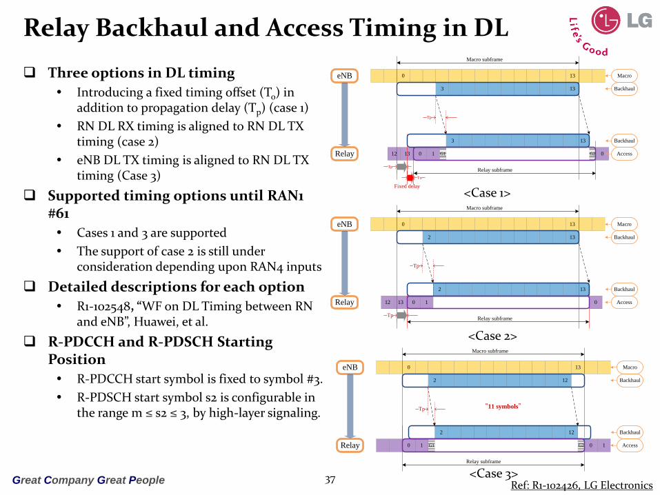
Relay Backhaul and Access Timing in DL
Three options in DL timing
Introducing a fixed timing offset (To) in addition to propagation delay (Tp) (case 1)
RN DL RX timing is aligned to RN DL TX timing (case 2)
eNB DL TX timing is aligned to RN DL TX timing (Case 3)
Supported timing options until RAN1 #61
Cases 1 and 3 are supported
The support of case 2 is still under consideration depending upon RAN4 inputs
Detailed descriptions for each option
R1-102548, “WF on DL Timing between RN and eNB”, Huawei, et al.
R-PDCCH and R-PDSCH Starting Position
R-PDCCH start symbol is fixed to symbol #3.
R-PDSCH start symbol s2 is configurable in the range m ≤ s2 ≤ 3, by high-layer signaling.
37
Fixed delay
0 13
3
012 13
eNB
Relay G1 G2
Macro subframe
Relay subframe
0 1
3
Macro
Backhaul
Backhaul
Access
Tp
Tp
13
13
To
0 13
012 13
eNB
Relay
Macro subframe
Relay subframe
0 1
Macro
Backhaul
Backhaul
Access
Tp
Tp
13
132
2
<Case 1>
<Case 2>
0 13
eNB
Relay
Macro subframe
Relay subframe
12
0 1 G1 G20 1
2
2 12
Tp
Macro
Backhaul
Backhaul
Access
“11 symbols”
<Case 3>Ref: R1-102426, LG Electronics

Great Company Great People
Relay Backhaul and Access Timing in UL
The following UL timing cases are supported without additional RAN1 specification required in Rel-10
Case 2b
UL RN Tx timing and UL RN Rx timing is staggered by a fixed gap (delayed Uu)
Modified case 2a
UL RN Tx timing and UL RN Rx timing is aligned
Modified case 4
UL eNB Rx and the UL RN Rx timing is aligned
LS to inform RAN2 and RAN4 for above agreement
Detailed descriptions of UL Timing options
R1-103399, “LS on UL timing between eNB and relay”
38
“To: Fixed delay
0 13
0 112
0
eNB
Relay G1 G2
Macro subframe
Relay subframe
Tp
Tp
13
13
Macro
Backhaul
Backhaul
Access
To
0
<Case 2b>
0 13
0 112 13
eNB
Relay
Macro subframe
Relay subframe
Tp
Tp
Macro
Backhaul
Backhaul
Access
0 13
0 13
<Modified Case 2a>
<Modified Case 4>
0 13
eNB
Relay
Macro subframe
Relay subframe
13
0 112 13 G1
1
Tp
G2
Macro
Backhaul
Backhaul
Access
13 1
RN can use SC-FDMA symbol 0 by puncturing the last SC-FDMA
symbol of the Uu link>
Ref: R1-102427, LG Electronics
Great Company Great People
Backhaul Resource Assignment
Agreement until RAN1 #61
Access link downlink subframe transmission boundary backhaul link downlink subframe reception boundary
Except for possible adjustment to allow for RN transmit/receive switching
Semi-statically explicit assignment of the set of downlink backhaul subframes
Introduction of a new physical control channel (here referred to as the “R-PDCCH”)
Dynamic or semi-persistent resource assignment for R-PDSCH or R-PUSCH
Resource assignment for R-PDCCH in the same and/or in one or more later subframes.
Within semi-statically assigned resource zone for R-PDCCH transmission,
A subset of the resource assignment used for R-PDCCH transmission
Subframe-by-subframe dynamic resource assignment for R-PDCCH transmission
Time-domain resource assignment of the full set of OFDM symbols or a constrained subset of OFDM symbols for R-PDCCH transmission
R-PDSCH or PDSCH transmission on the resources not used for R-PDCCH
Possible reuse of Rel-8 functionality for the detailed R-PDCCH transmitter processing (channel coding, interleaving, multiplexing, etc.)
Allowance of removing some unnecessary procedure or bandwidth-wasting procedure by considering the relay property
39
Great Company Great People
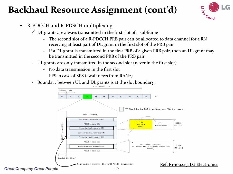
Backhaul Resource Assignment (cont’d)
R-PDCCH and R-PDSCH multiplexing
DL grants are always transmitted in the first slot of a subframe
- The second slot of a R-PDCCH PRB pair can be allocated to data channel for a RN receiving at least part of DL grant in the first slot of the PRB pair.
- If a DL grant is transmitted in the first PRB of a given PRB pair, then an UL grant may be transmitted in the second PRB of the PRB pair
- UL grants are only transmitted in the second slot (never in the first slot)
- No data transmission in the first slot
- FFS in case of SPS (await news from RAN2)
- Boundary between UL and DL grants is at the slot boundary.
40
#0 #1 #2 #3 #4 #5 #6 #7 #8 #9 #0
subframe 1ms
10 ms eNB radio frame
PDSCH to macro UEs
Primary backhaul resource for RN1
Primary backhaul resource for RN3
Secondary backhaul resource for RN2
Primary backhaul resource for RN2
Secondary backhaul resource for RN3
PDSCH to macro UEs
Semi-statically assigned PRBs for R-PDCCH transmission
PD
CC
H to
mac
ro U
Es
PDSCH to macro UEs
GT GT
GT GT
GT GT
Additional R-PDSCH to RN3
(indicated by R-PDCCH to RN3 in primary backhaul
resource)
2nd slot
R-PDSCH to RN3
...
PDSCH to macro UEs
GT: Guard time for Tx/RX transition gap at RNs if necessary.
1st slot
R-PDCCH
to RN3
N PRBs
(N=1,2,…)
M PRBs
(M=1,2,…)
K symbols (K=1,2,3 or 4)
Ref: R1-100225, LG Electronics

Great Company Great People
Relay: Backhaul DM-RS Design
Agreement until RAN1 #61
Starting point for RS design for each eNodeB-to-RN channel demodulation
Reuse of RS designed for eNB-to-UE transmission (i.e., Rel-8 CRS and/or Rel-10 DM-RS)
For R-PDCCH,
For a given RN, R-PDCCH demodulation RS type (CRS or DM-RS) shall not change dynamically nor depend on subframe type.
Demodulate with
- In normal subframes:
» Rel-10 DM-RS when DM-RS are configured by eNB
» Otherwise Rel-8 CRS
- In MBSFN subframes, Rel-10 DM-RS
For downlink shared data transmission on Un
Same possibilities as for R-PDCCH
Un DM-RS pattern for DL timing case 3
Alt 1: Reduced DM-RS
Alt 2: Shifted DM-RS
One alternative between Alt 1 and Alt 2 will be down-selected
- Targeting RAN1#61bis
41
Alt 1: Reduced DM-RS
Alt 2: Shifted DM-RS

Great Company Great People
Backhaul Subframe Allocation and HARQ Timing
Consideration points
Restriction on backhaul downlink subframe allocation
FDD: subframe indices of {0, 4, 5, 9}
TDD: subframe indices of {0, 1, 5, 6}
Backhaul DL/UL HARQ timing relationship
Support of LTE Rel-8 UE’s HARQ in the access link
Problematic situation for backhaul HARQ
Agreements in HARQ until RAN1 #61 For both FDD and TDD backhaul link, release 8 minimum HARQ RTT timing is the
baseline assumption for DL and UL minimum requirement from L1 processing perspective
42

Great Company Great PeopleGreat Company Great People 4343
DL MIMO Enhancement

Great Company Great People 44
LTE-A DL RS Configuration
DL reference signal configuration in an LTE-A cell
LTE Rel-8 cell-specific reference signal (CRS)
Demodulation for PDCCH, PCFICH, PHICH, and PDSCH(TxD)
L3 measurement (RSRP/RSRQ) measurement or [L2 measurement]
LTE-A demodulation reference signal (DM-RS)
Demodulation for PDSCH except TxD mode
LTE-A channel status information reference signal (CSI-RS)
L2 measurement
Potential reference signal configuration
LTE-A subframe (MBSFN subframe)
LTE-A optimized unicast transmission in an MBSFN subframe
By control signaling for MBSFN subframe configuration
No legacy CRS REs in the PDSCH region
Issue point
TxD transmission and its relevant RS configuration in an LTE-A subframe
1Tx CSI-RS 2Tx CSI-RS 4Tx CSI-RS 8Tx CSI-RS
1Tx CRS X ? ? O
2Tx CRS - X ? O
4Tx CRS - - X O
X: Rel-8 CRS can be used as CSI-RS for LTE-A system
O: new CSI-RS for LTE-A antenna configuration is needed

Great Company Great People45
LTE-A DL DM-RS Design
LTE-A DL DM-RS pattern in case of normal CP
For rank-1 and rank-2
12 REs, CDM, time-domain OCC of length-2
For rank-3 and rank-4
24REs, CDM+FDM, time-domain OCC of length-2
For rank-5~8
24REs, CDM+FDM, time-domain OCC of length-4
LTE-A DL DM-RS patterns in case of extended CP
Working Assumption:
In case of rank 1-2, DM-RS overhead of 16 REs per PRB pair for extended CP with normal subframe
FFS on detailed pattern
Normal subframe DwPTS with 11,12
OFDM symbols
DwPTS with 9,10
OFDM symbols Ref: R1-100800 NTT DoCoMo

Great Company Great People
DM-RS Port to Layer Mapping
Working assumptions DM-RS power offset for rank>2
Fixed 3dB power offset to corresponding layer
Definition of DM-RS port resource with two CDM groups for rank>2 1st CDM group :{port-7, port-8, port-11, port-13} 2nd CDM group :{port-9, port-10, port-12, port-14}
DM-RS port to layer mapping for rank>2 Layer n corresponds to port-(n+7), n=0,…,7 One-to-one mapping between DM-RS port and layer
For retransmission with rank = R, the same layer to DMRS port mapping rule and the same PDSCH to RE mapping rule are applied as an initial transmission with rank R
46
Ref: R1-102462, LG Electronics

Great Company Great People
PRB Bundling and Details of OCC
PRB bundling
PRB bundling means that
UE may assume that precoding granularity is multiple RBs.
UE is still allowed to perform single-RB channel estimation
PRB bundling is supported when PMI/RI feedback is configured
Additional configuration of PRB bundling is FFS
The size of a PRG is only determined by the corresponding system bandwidth
FFS for details of OCC
Sequence design for OCCs and scrambling codes
47
System Bandwidth PRG size (PRB)
≤10 1
11 – 26 2
27 – 63Either 2 or 3
(decide in RAN1 #61bis)
64 – 110 2

Great Company Great People48
LTE-A DL CSI-RS Design
CSI-RS density 1RE per port per PRB for 2, 4, 8 Tx cases
Full-power utilization and CSI-RS multiplexing Negative response for 9 dB boosting per antenna
CSI RS port multiplexing is based on CDM for each pair of CSI RS port
Same data RE power between a data RE in the OFDM symbol containing CSI-RS and a data RE in the OFDM symbol without CSI-RS/Rel-8 CRS is assumed within a subframe
A nested structure among 2, 4, 8 CSI-RS ports simplifies the implementation The pattern with smaller number of CSI-RS port is a subset of the pattern with larger number of
CSI-RS port
No hopping supported A time-invariant time/frequency shift is used in a cell
Resource elements (REs) of CSIRS are configured and/or tied to system parameters for inter-cell orthogonality, i.e, no collision between CSI-RS.
Further consideration points Exact CSI-RS pattern design
Antenna port based multiplexing details
The number of OFDM symbols for CSI-RS transmission
Per antenna full-power utilization
Details on CSI-RS transmission
Period and offset considering channel measurement feedback procedures
Consideration on inter-cell CSI-RS transmission
Channel measurement for multi-cell collaborative transmission
Interference measurement
Great Company Great People
SU-/MU-MIMO
8Tx codeword-to-layer mapping
Simple extension of legacy LTE codeword-to-layer mapping
Dynamic mode adaptation btw. LTE-A DL SU-/MU-MIMO
Same DCI format design based on UE-transparency in terms of DL control signaling
MU-MIMO baselines
Dimensioning
Co-scheduling up to 4 UEs
Number of layers per UE with orthogonal RS of up to 2
Total number of layers for MU-MIMO transmission of up to 4
Further consideration points
UE-transparency on feedback btw. LTE-A SU-MIMO and MU-MIMO
Resource allocation of orthogonal RS ports and scrambling code for MU-MIMO
Details on DCI format design
Detailed feedback procedures for SU-MIMO and MU-MIMO
49

Great Company Great People
Feedback for LTE-A
Implicit feedback (PMI/RI/CQI) is used also for Rel-10 UE spatial feedback for a subband represents a precoder (as constructed below) CQI computed based on the assumption that eNodeB uses a specific precoder (or
precoders), as given by the feedback, on each subband within the CQI reference resource Note that a subband can correspond to the whole system bandwidth
A precoder W for a subband is a function of two matrices W1 and W2, i.e. where W1 C1 and W2 C2. The codebooks C1 and C2 are codebooks one and two, respectively.
W1 targets wideband/long-term channel properties
W2 targets frequency-selective/short-term time channel properties
For PUCCH, the feedback corresponding to W1 and W2 can be sent in different or the same subframe (unless it turns out that the payload is too large to ever send W1 and W2 in the same subframe on PUCCH). Periodic and aperiodic reports are independent For PUSCH: FFS FFS whether feedback corresponding to W1 and/or W2 may be switched off
50

Great Company Great People
Feedback Signaling
Aperiodic PUSCH: Natural extension of CQI/PMI/RI modes from Rel-8/9 within R1-101683
framework
The report in aperiodic PUSCH is self-contained in the same subframe One report can contain both W1 and W2
In case one of W1/W2 is fixed, one report can contain W1 only or W2 only- Regardless of which, the precoder W is derived from W1 and W2
The same report contains RI and CQI
Periodic PUCCH Natural extension of CQI/PMI/RI modes from Rel-8/9 within R1-101683
framework
W_1/W_2 reporting procedure CSI Mode 1: W1 and W2 are signaled in separate subframes
- W2 could be wideband or subband
CSI Mode 2: W is determined by a single report confined to a single subframe, e.g.- one of W1/W2 could be fixed and hence does not need to be signaled
- W1/W2 is not fixed but still does not necessarily need to be signaled
» But the precoder W is still derived from W1 and W2
- W2 could be wideband (i.e., subband size could be the system bandwidth)
FFS: RI and CQI reporting details
51

Great Company Great PeopleGreat Company Great People 5252
UL MIMO Enhancement

Great Company Great People
Channel-Independent MIMO Tx.
Single antenna port mode
In this mode, the UE behavior is same as the UE behavior with single antenna from eNB’s perspective.
Exact UE implementation is left to UE vendors (e.g., PA architecture).
PUCCH, and/or PUSCH, and/or SRS transmission can be independently configured for single uplink antenna port transmission.
Detail scenarios and operation FFS.
UL Single Antenna Port Mode is the default operation mode before eNodeB is aware of the UE transmit antenna configuration.
No definition of PUSCH transmit diversity scheme
Long-term rank-1 precoding
53
Great Company Great People
Channel-Independent MIMO Tx. (cont’d)
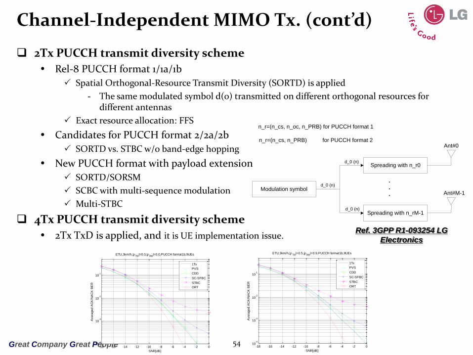
2Tx PUCCH transmit diversity scheme
Rel-8 PUCCH format 1/1a/1b
Spatial Orthogonal-Resource Transmit Diversity (SORTD) is applied
- The same modulated symbol d(0) transmitted on different orthogonal resources for different antennas
Exact resource allocation: FFS
Candidates for PUCCH format 2/2a/2b
SORTD vs. STBC w/o band-edge hopping
New PUCCH format with payload extension
SORTD/SORSM
SCBC with multi-sequence modulation
Multi-STBC
4Tx PUCCH transmit diversity scheme
2Tx TxD is applied, and it is UE implementation issue.
54
Modulation symbol
Spreading with n_r0
Spreading with n_rM-1
n_r=(n_cs, n_oc, n_PRB) for PUCCH format 1
n_r=(n_cs, n_PRB) for PUCCH format 2Ant#0
Ant#M-1
d_0 (n)
d_0 (n)
d_0 (n)
.
.
.
-18 -16 -14 -12 -10 -8 -6 -4 -2 010
-4
10-3
10-2
10-1
SNR[dB]
Avera
ged A
CK
/NA
CK
BE
R
ETU,3km/h,|TX
|=0.0,|RX
|=0.0,PUCCH format1b,9UEs
1Tx
PVS
CDD
SC-SFBC
STBC
ORT
-18 -16 -14 -12 -10 -8 -6 -4 -2 010
-4
10-3
10-2
10-1
SNR[dB]
Avera
ged A
CK
/NA
CK
BE
R
ETU,3km/h,|TX
|=0.5,|RX
|=0.9,PUCCH format1b,9UEs
1Tx
PVS
CDD
SC-SFBC
STBC
ORT
Ref. 3GPP R1-093254 LG
Electronics

Great Company Great People
Uplink SU-MIMO
Codebook-based precoding
Independent codebook design for different ranks
Single TPMI per UL component carrier
Frequency non-selective precoding in a component carrier
TPMI size: 3bit (2Tx), 6bit (4Tx)
- Possibly can be reduced.
Transmission mode and signaling
At least two new Rel-10 UE-specific RRC-configured transmission modes for PUSCH of UE with multiple APs:
Single-antenna port mode
Multi-antenna port mode supporting up to 2 TB (the number of antenna ports depends on the UE capability).
FFS whether or not a third RRC-configured multi-antenna transmission mode is needed
For PUSCH, a dynamic switching between the configured transmission scheme and a single-port fallback scheme with the same DCI format for all RRC configured modes.
55

Great Company Great People
Uplink SU-MIMO (cont’d)
Further consideration points
Impact on antenna gain imbalance (AGI) due to hand-gripping problem
Per-antenna power control
Antenna power amp (PA) configuration
2Tx antennas
- Case-1: 20dBm + 20dBm
- Case-2: 23dBm + 23dBm
- Case-3: 23dBm + x, where x23dBm
4Tx antennas
- Case-1: 17dBm + 17dBm + 17dBm + 17dBm
- Case-2: 23dBm + 23dBm + 23dBm + 23dBm
- Case-3: 23dBm + x + x + x, where x 23dBm
UL SU-MIMO precoding in PHICH-triggered retransmissions
Different precoding matrix selection and configuration method for retransmissions
56

Great Company Great People
UL 2Tx Codebook Design
57
1
1
2
1
Codebook
indexNumber of layers
1 2
0
1
2
3 -
4
5
1
1
2
1
10
01
2
1
j
1
2
1
j
1
2
1
0
1
2
1
1
0
2
1
Antenna turn-off vectors against AGI situation
2Tx rank-1 & 2 codebook

Great Company Great People
UL 4Tx Codebook Design – Rank 1
4Tx rank-1 codebook
Size-24: 16 constant modulus + 8 antenna-pair turn-off vectors
QPSK alphabet for rank-1 precoding proposals other than the rank-1 precoding specified in LTE Rel-8
58
Index 0
to 7
Index 8
to 15
Index 16
to 23
1
1
1
1
2
1
j
j
1
1
2
1
1
1
1
1
2
1
j
j
1
1
2
1
j
j
1
1
2
1
1
1
2
1
j
j
j
j
1
1
2
1
1
1
2
1
j
j
1
1
1
1
2
1
j
j
1
1
2
1
1
1
1
1
2
1
j
j
1
1
2
1
j
j
1
1
2
1
1
1
2
1
j
j
j
j
1
1
2
1
1
1
2
1
j
j
0
1
0
1
2
1
0
1
0
1
2
1
0
0
1
2
1
j
0
0
1
2
1
j
1
0
1
0
2
1
j
0
1
0
2
1
j
0
1
0
2
1
1
0
1
0
2
1
Antenna turn-off vectors against AGI situation

Great Company Great People
UL 4Tx Codebook Design – Rank 2
4Tx rank-2 codebook
Size-16: CM-preserving matrices
QPSK alphabet
59
Index 0
to 7
Index 8
to 15
j
1
0
0
0
0
1
1
2
1
j
1
0
0
0
0
1
1
2
1
1
1
0
0
0
0
1
2
1 j
1
1
0
0
0
0
1
2
1 j
j
1
0
0
0
0
1
1
2
1
j
1
0
0
0
0
1
1
2
1
1
1
0
0
0
0
1
2
1 j
1
1
0
0
0
0
1
2
1 j
1
0
1
0
0
1
0
1
2
1
1
0
1
0
0
1
0
1
2
1
1
0
1
0
0
1
0
1
2
1
1
0
1
0
0
1
0
1
2
1
0
1
1
0
1
0
0
1
2
1
0
1
1
0
1
0
0
1
2
1
0
1
1
0
1
0
0
1
2
1
0
1
1
0
1
0
0
1
2
1

Great Company Great People
UL 4Tx Codebook Design – Rank 3 & 4
4Tx rank 3 codebook
Size-12 : CM-preserving matrices
BPSK for simplicity
4Tx rank-4 codebook
Single identity matrix
60
Index 0
to 3
Index 4
to 7
Index 8
to 11
100
010
001
001
2
1
100
010
001
001
2
1
100
001
010
001
2
1
100
001
010
001
2
1
001
100
010
001
2
1
001
100
010
001
2
1
100
001
001
010
2
1
100
001
001
010
2
1
001
100
001
010
2
1
001
100
001
010
2
1
001
001
100
010
2
1
001
001
100
010
2
1

Great Company Great People
DM-RS and Orthogonal Cover Code (OCC)
Precoded UL DM-RS
2Tx antennas
Precoded DM-RS both for rank-1 and rank-2 (using identity matrix)
4Tx antennas
Precoded DM-RS for all rank cases
- DM-RS precoding for rank-4 (using identity matrix)
- Potential agreement of precoded DM-RS in case of rank-3
UL DM-RS multiplexing
Baseline: cyclic shift (CS) separation for DM-RS multiplexing
Segmentation based DM-RS sequence mapping for non-contiguous RB allocation for MU-MIMO
Introduce the OCC in Rel-10 without increasing UL grant signaling overhead
OCC can be used for both SU and MU-MIMO
FFS
- Cyclic shift configuration for multiple layers
- Configuration between OCC and CS index
Sequence hopping/sequence group hopping
Rel-8/9 cell-specific enabling or disabling of sequence group hopping is available in Rel-10
FFS for introducing new hopping mechanism
61

Great Company Great People
Enhanced SRS
Baseline assumptions for enhanced SRS
Periodic SRS: Re-use of Rel-8 principles (CS separation, IFDM separation)
Non-precoded (antenna specific) SRS for LTE-A UE
Independent SRS configuration per CC in case of carrier aggregation
Aperiodic SRS
Triggering method
At least supported by PDCCH UL grants
- In case of DCI format 0 is used for SRS triggering, size of DCI format 0 remains the same as defined in Rel8 at least in common search space
FFS for allowing triggering without PUSCH grant
FFS for triggering by DL grant and by DCI format 3/3A
SRS duration
One-shot SRS transmission is supported.
FFS for timer-based aperiodic SRS
FFS for resources used for aperiodic SRS
Reuse of Rel-8 periodic SRS resources
Introduction of new SRS resources, e.g., sounding via DM-RS
FFS for SRS configuration for multi-antenna support
Simultaneous SRS transmission from all transmit antennas
SRS transmission from partial transmit antennas
62

Great Company Great People
Layer Shifting/HARQ Bundling for UL SU-MIMO
No Layer shifting
Changes in layer-to-port mapping every SC-FDMA symbol
No support for layer shifting in Rel-10
No HARQ bundling for UL SU-MIMO
2 NDIs (one NDI per CW) in the DCI format associated with UL SU-MIMO.
2 HARQ A/N Limit PHICH design to one to one mapping between an A/N and an existing
PHICH resource
For a single CC UL MIMO transmission, the PHICH resources for CW1 and CW2 are identified by
- The CSI value associated with the PUSCH transmission
- Different PRB indices for the PUSCH, assuming more than one PRBs for the transmission
- (I,Q) branches of a QPSK symbol within one PHICH group
63

Great Company Great People
UCI Piggybacking
UCI Piggybacking for SU-MIMO
HARQ-ACK and RI:
Replicated across all layers of both CWs
TDM multiplexed with data such that UCI symbols are time-aligned across all layers FFS: How to determine the number of UCI symbols on each CW and each layer
CQI/PMI: transmitted only on 1 codeword
Reuse Rel-8 multiplexing and channel interleaving mechanisms Extension: The input to data-control multiplexing { , } is grouped into
column vectors of length Q_m*L
- L (1 or 2) is the number of layers the CW is mapped onto
- Enable time (RE) alignment across 2 layers for L=2
UCI symbol-level layer mapping: same as (treated as a part of) data
FFS: Mechanism for CW selection
64
0 1 2 3 1, , , ,...,CQIQq q q q q 0 1 2 3 1, , , ,..., Gf f f f f
0 1 2 3 1, , , ,...,
Hg g g g g
CQI
RI
ACK
RS RS
DATA
SC-FDM symbols
time
do
ma
in m
od
ula
ted
sym
bo
ls
for e
ach
SC
-FD
M s
ym
bo
l
Rel-8 UCI Piggybacking in PUSCH UCI Piggybacking for multiple layers
Ref: R1-102762, Qualcomm

Great Company Great People
References
Chairman’s notes RAN1 #59bis, #60, #60bis, and #61
3GPP TS 36.211: "Evolved Universal Terrestrial Radio Access (E-UTRA); Physical channels and modulation".
3GPP TS 36.212: “Evolved Universal Terrestrial Radio Access (E-UTRA); Multiplexing and channel coding".
3GPP TS 36.213: "Evolved Universal Terrestrial Radio Access (E-UTRA); Physical layer procedures".
3GPP TR 36.814: “Further Advancements for E-UTRA Physical Layer Aspects”
Stephen Hayes , “3GPP Technology Standards Roadmap Mobile Broadband Outlook for the Americas”, Mobile Broadband Outlook for the America, Apr. 2010.
Takehiro Nakamura, “Proposal for Candidate Radio Interface Technologies for IMT-Advanced Based on LTE Release 10 and Beyond (LTE-Advanced)” ITU-R WP 5D 3rd Workshop on IMT-Advanced, Oct. 2009.
Jaehoon Chung, “3GPP LTE-Advanced: Physical Layer Technologies”, 16th Wireless Communications Workshop .
65

Great Company Great PeopleGreat Company Great People 6666
QnA