Embed Size (px)
Citation preview

Kernel−based Linux emulation for Plan 9
ABSTRACT
CNKemu is a kernel-based system for the 9k variant of the Plan 9 kernel.It is designed to provide transparent binary support for programs compiled for IBM�s Compute Node Kernel (CNK) on the Blue Gene series ofsupercomputers. This support allows users to build applications with thestandard Blue Gene toolchain, including C++ and Fortran compilers.While the CNK is not Linux, IBM designed the CNK so that the user interface has much in common with the Linux 2.0 system call interface. ThePlan 9 CNK emulator hence provides the foundation of kernel-basedLinux system call support on Plan 9. In this paper we discuss cnkemu�simplementation and some of its more interesting features, such as theability to easily intermix Plan 9 and Linux system calls.
Introduction
We have ported Plan 9 to the IBM Blue Gene series of supercomputers. There are twosystems we are currently using, one of which has 1024 4-core PPC 450 CPUs, and onewhich has 40,000 CPUs. These systems also have several special purpose networks.
The goal of the work is to evaluate Plan 9 as an operating systems for such machines.One issue is that the toolchain for these machines is Linux-centric and can not beported to Plan 9 in any reasonable timeframe: the compilers are not available in sourceform in some cases; the runtime library code consists of a mix of C and C++; the applications code is a mix for Fortran, C, C++, and Python. Rewriting all the apps is simplyimpossible, as they consist of milions of lines of code. The only possible path to evaluating these applications under Plan 9 is an emulation system.
Operating systems of one type have been able to support programs from another operating system for a very long time. In recent times, some kernels such as FreeBSD haveprovided support for Linux. This support is provided in the kernel, via a switch to anentirely seperate system call table. More recently, Plan 9 has supported Linux binariesvia LinuxEMU, which relies on the fact that Linux system calls use a trap to vector 80,and Plan 9 uses a trap to vector 40. The Linux trap can thus be handled by the Plan 9__________________Sandia is a multiprogram laboratory operated by Sandia Corporation, a Lockheed Martin Company,
for the United States Department of Energy�s National Nuclear Security Administration under contract
DEAC0494AL85000. SAND- 2011-6644C
2
notes mechanism, since the trap 80 used by Linux will bounce from kernel mode to usermode if a handler is set up. Linuxemu is an interesting example of how to implement asmall operating system in user mode. One limitation of LinuxEMU is performance: thetrap results in the creation of a string, which is passed to user mode and has to beparsed. Also, as we discuss below, there are some operations that have to be done bythe kernel, that the LinuxEMU approach can not support.
Another issue on the Power PC is that there is only one system call instruction for alloperating systems. All programs will trap to the system call handler in the kernel. Stillworse, there is an overlap in the system call number space: there is no way to differentiate programs based on the system call vector used or the system call number used.Therefore, the process must be marked in some way, and a system call switch made inthe kernel. In this paper, we discuss the requirements of CNK binaries, our usage ofCNKemu and then our implementation.
CNK binaries
CNK programs are statically linked, with the components on 1 Mbyte boundaries. Thelowest address used is 16 Mbytes. The text segment is first, followed by the data segment. Stack is at the top of the user address space. Heap starts on the first 1 Mbyteboundary after data, and extends as needed. Heap must stop at the lowest 1 Mbyteboundary below the stack, but this quantity is dynamic.
The program is linked with standard libraries such as GNU libc; as well as optionallibraries such as MPI and the IBM Deep Computing Message Facility (DCMF). The systemcall interface consists of the standard Linux system call set and a set of CNK-specificsystem calls starting at 1024.
On the PowerPC system calls are executed via the sc instruction. System call parametersare in registers r3-r8; return value is in r3.
Programs on the CNK are started by the CNK itself. The program text and data are readinto memory and the program started at its entry point (determined from the programfile). There is no notion of swap: any page faults can be dealt with entirely by what is inmemory, or by allocating new anonymous memory pages.
The mmap system call is used to allocate anonymous memory for the allocator. Thestandard GNU malloc is used; care must be taken to ensure that the malloc does not tryto give memory back via munmap; this behavior in malloc is designed to optimize memory footprint in a time-shared node, and is totally unnecessary on a Blue Gene system inwhich CPUs are single-user, single-process systems.
Threads on the CNK are created by a limited-function version of the Linux clone systemcall. The threads share all memory with the parent process, including the parent stack;hence, part of thread creation is the definition of the thread stack. It is possible to create a kernel thread by setting a special-purpose register (SPRG0) to a special value,since the standard Linux clone interface does not have enough information to indicate akernel thread is desired.
CNK argument passing is as on Linux: an arg count and an array of null- terminatedstrings (i.e.: argc, argv) are passed in to the programs entry point. The CNK sets up environment variables in the usual fashion: null-terminated name-value pairs starting atargv[-1].
3
Using CNKemu
To use CNKemu, one must have a process to set the system up. In many ways, thissetup process is similar to what is in LinuxEMU: parsing of an ELF binary, setting up critical environment variables, and then running the process. We call this program machcnk.
Machcnk takes a command name and options. Options to machcnk enable kernel printing of system call arguments and ureg values, before and after the system call or both;and per-system call information. Machcnk opens and validates the ELF binary using libmach; sets up several memory segments for the program, at virtual addresses matchingthe ELF segments; reads the text and data in, and jumps to the entry point.
At that point, one has a binary running on Plan 9, apparently (to the binary) in a full CNKenvironment. There are many interesting possibilites, however. Since the basic file system calls are identical in each environment, and in fact run through the same code inthe Plan 9 kernel, programs can test which environment they are in by existence testson files. Hence, the same program can run on Plan 9 and CNK, and use all the Plan 9capabilities that exist -- since, on Plan 9, one can do just about everything with file I/O.We already use this capability in a limited way -- in one program, we test for/dev/bintime and use that instead of the system calls for timing that CNK makes available.
More interestingly, we can switch back and forth between CNK and Plan 9 native modes.The mode that a program uses (CNKemu or Plan 9 native) is chosen by writing �1� or �0�to #P/cnk. A program can run in Plan 9 mode, setting up the namespace; then shiftgears and run as a CNK program for a while, then shift back to alter the environmentsome more.
Going still further, we can write programs that run as Plan 9 native while using theLinux-based toolchain. We can thus use advanced compilers and build tools developedfor the Blue Gene to create highly optimized programs for Plan 9, and to compare therelative efficiency of the Plan~9 and gcc compilers.
This flexibility allows us to very directly compare the relative performance of the CNK,Linux, and Plan 9 operating systems on Blue Gene. In each case, the binary is the same.
Implementation
CNK emulation is implemented as a set of changes to the 9k Plan 9 kernel and a program to start up and run programs. The kernel changes allow a process to be marked asbeing in CNK emulation; and include the code necessary to either directly support a CNKsystem call or map a CNK system call to its Plan 9 equivalent.
As mentioned above, processes have to be marked in some way. The common method isto introduce a new variable into the Proc struct, and CNK support follows this model. InPlan 9, the proc struct is defined in the port/portdat.h, i.e. it has an architecture-independent definition. Because CNK support is very much architecture-dependent, theflag must be introduced into the architecture-dependent part of the struct. There arenot many options, as one can see in the Proc structure:

4
/** machine specific fpu, mmu and notify*/
PFPU;PMMU;PNOTIFY;
It might be useful at some point to introduce a general-purpose machine specific structcalled ARCH, for this type of thing. CNK support doesn�t really fit into any of the FPU,MMU, or NOTIFY structs. Neverthelss we hide it in the PMMU struct for bgp.
Devarch.c is extended with a new file, cnk, which allows up->cnk to be set and clearedby writing a �1� or �0� to #P/cnk.
The only visible effect that setting cnk has is that in the trap code, the kernel usesup−>cnk to determine whether to call the regular system call or cnksyscall, viz.:
voidtrap(Ureg *ur){
u32int dear, esr;char buf[ERRMAX];int ecode, user;
ur->cause &= 0xFFE0;ecode = ur->cause;
.
.
.switch(ecode){
case INT_SYSCALL:if(!user)
panic("syscall in kernel: srr1 %#4.4luX pc %#p0,ur->srr1, ur->pc);
if(up->cnk)cnksyscall(ur);
elsesyscall(ur);
return; /* syscall() calls notify itself */
CNK system calls
The CNK support code is maintained in a new directory in the 9k tree called cnk.
An array of structs is initialized at compile time with pointers to functions or, if the callis not supported, pointers to nil. We excerpt a portion of this file below to show bothhow it works and also the way that some cnk functions are directly mapped to Plan 9functions.

5
struct syscall {char* n;Syscall*f;int narg;Ar0 r;
};
struct syscall cnksystab[] = {[4] {"write", sys_write, 3, {.i = -1}},[5] {"cnkopen", sysopen, 2, {.i = -1}},[24] {"getuid", cnkgeteuid, 0, {.i = -1}},[180] {"pwrite64", syspwrite, 5, {.i = -1}},
The struct itself has the name of the system call for debug prints, a function pointer,parameter count, and default return value. It is almost identical to the standard syscallstruct.
As can be seen, the two CNK write system calls are directly connected to their Plan 9equivalents: the result is that IO in the CNK emulator has very little overhead, and certainly far less overhead than the note-based mechanism used for LinuxEMU.
Not all CNK system calls have a Plan 9 equivalent: geteuid being one example. In thiscase we provide an emulation, as shown below:
voidcnkgeteuid(Ar0 *ar0, va_list){
ar0->i = 0;}
The person running on the machine is always the owner; the only reasonable equivalentis uid 0.
Mmap is a much more complex case; we only need to support the anonymous memorymapping function for now. We will walk through it step by step.
void cnkmmap(Ar0 *ar0, va_list list){
void *v;int length, prot, flags, fd;ulong offset;
v = va_arg(list, void *);length = va_arg(list, int);prot = va_arg(list, int);flags = va_arg(list, int);fd = va_arg(list, int);offset = va_arg(list, ulong);
This initial code just sets up the arguments. Next we determine if the allocation can beaccomodated:

6
if (fd == -1){Segment *heapseg = up->heapseg;unsigned char *newv, *oldv;uintptr arg;arg = PGROUND(heapseg->top);
We only allocate anonymous memory at present, hence the if. Linux programs markanonymous memory mmap calls by using an fd of -1. The code starts the allocation atthe next page above the top of the heap segment.
cnksbrk(ar0, arg, 0);
The cnksbrk is a new function that does almost exactly what sbrk does, with one difference: it calls fault to pre-emptively allocate all the pages in the allocated area. Thisaction avoids further page faults (which are very expensive on the PPC) and also avoidsany chance of overcomitting memory, which is a bad idea on a machine with no swap. Infuture, when we have large TLB support finalized in the kernel, we will further modifythis function so that, if the allocation unit is a multiple of 1 Mbyte, it will be allocatedwith 1 Mbyte alighment, so we can back it with 1 Mbyte TLBs.
To enable and disable zero-filling on page faults, we have extended the standard Plan 9segment structure with a new attribute, nozfod. Nozfod allows for eventual supportof munmap. On most operating systems munmap is supported by splitting the segmentinto two, with a hole in between them equivalent to the unmapped area. Plan~9 onlysupports a very limited number of segments. What we can do instead is remove thepage mapping from the heap segment. Since the segment is
The cnk system call code to call the functions is quite similar to the standard PPC system call code save for the fact that gcc puts all system call parameters in registers. Toaccomodate qc calling conventions we put those arguments into an array and then callthe function. The code, boiled to its essence:
linuxargs[0] = ureg->r3;linuxargs[1] = ureg->r4;linuxargs[2] = ureg->r5;linuxargs[3] = ureg->r6;linuxargs[4] = ureg->r7;linuxargs[5] = ureg->r8;cnksystab[scallnr].f(&ar0, (va_list)linuxargs);
User mode code
The program to set up and run CNK binaries is called machcnk. It uses libmach (hencethe name) to read the binaries in, set code, data, environment, arguments, and stack up,and jump to the entry point of the binaries. Rather than start the binary as a seperateprogram, it reads the binary in to to memory and sets up required memory segments.The binary is hence entered via a function call, not exec.
We will describe some of the more important parts of this code.
The first step is to read the file in and crack the header with libmach. This informationdetermines the address space and size; code, data, and heap segments are attachedwith the correct sizes and permissions. The top of heap is the stack and it must ofcourse be initialized. We have a modified version of libmach as we need a bit more information than is provided by the standard library.

7
The program stack is initialized with the argument count, argument vector, environment, and aux vector, with argument vector at the bottom of stack (lower address). Weexplain the aux vector below.
It is not possible to function with an empty environment. In fact one of the most challenging parts of this code was figuring out the minimum set of environment variables.Getting all the internationalization code to work correctly was difficult simply becausethe GNU code is not an exemplar of coding style. Problems with this code came up thefirst time the GNU runtime tried to print a startup message, and the code tried to figureout to print what in some parts of the world is a "." and in other parts is a ",". In mostcases, the GNU internationalization code would explode because not all the support fileswere there -- there are potentially hundreds of them. Since all the GNU internationalization libraries are named in the binary, but the files themselves not set up on the node, itis critical to convince the GNU library to not even bother looking for them. which is doneby setting LANG to C.
Another problem is GNU malloc. It will, for larger allocations, use mmap to allocate thedata area. Conversely, it uses munmap to free the data -- this is a time-sharing decision aimed at making memory avaiable to other programs. Such cooperative behaviouris hardly necessary on single-user supercomputer nodes, however. Frequent calls tommap/munmap for allocation impact allocator performance. Worse, the Plan 9 virtualmemory code is not capable of supporting an munmap operation, which requires in theworst case that a segment be split in two. As it happens one can disable the GNU mallocbehavior by setting the environment variable MALLOC_MAP_MAX to 0.
The "aux vector" is a set of variables maintained on the stack just after the last argventry. The aux vector is similar in nature to Plan 9�s top of stack struct, except that it isnot a struct, but rather a set of key-value pairs, with the key being a binary number andthe value being a binary number. In a sense, it is a binary form of the environment variables. Without some aux settings programs can not run at all; machcnk sets the minimum.
Finally, machcnk sets the execution mode to cnk emulation by writing to �1� to#P/cnk and calls the entry point to the binary as it would any other function. Here iswhere the CNK ELF layout helped a good deal. CNK code starts at 16 MB binary; the Plan9 support code and the CNK binary can easily coexist. In fact, if the CNK main returns,the machcnk program can do post-processing if it is ever needed.
Results
We are now able to compile a number of programs on Linux and run them on Plan 9 orthe CNK with no change, and no performance penalty. The programs can unknowinglyexploit Plan 9 capabilities, since wrapper scripts can set up name spaces and cachingfile systems such as fscfs. Performance comparisons are now easy to make.
Conclusions
We have extended Plan 9 to transparently support binaries conforming to the Linux 2.0system call interface. Programmers can flip modes very easily, by writing to #P/cnk,since the the same read and write system calls are called in either mode. Programmerscan even write �native� Plan 9 programs, build them with the advanced Linux tool chain,and run them on Plan 9. We have thus made a full suite of optimizing compilers available to users of Plan 9 on BG/P.

Easy system call tracing for Plan 9
ABSTRACT
Tracing system calls makes debugging easy and fast. On Plan 9, traditionally, system call tracing has been implemented with acid(1). New systemsdo not always implement all the capabilities needed for Acid, particularlythe ability to rewrite the process code space to insert breakpoints. Architecture support libraries are not always available for Acid, or may notwork even on a supported architecture. The requirement that Acid�slibraries be available can be a problem on systems with a very smallmemory footprint, such as High Performance Computing systems whereevery Kbyte counts. Finally, Acid tracing is inconvenient in the presenceof forks, which means tracing shell pipelines is particularly troublesome.The strace program available on most Unix systems is far more convenient to use and more capable than Acid for system call tracing. A similarsystem on Plan 9 can simplify troubleshooting. We have built a systemcalling tracing capability into the Plan 9 kernel. It has proven to be moreconvenient than strace in programming effort. One can write a shell scriptto implement tracing, and the C code to implement an strace equivalentis several orders of magnitude smaller.
Introduction
System call tracing is an important and effective way to debug programs. With a systemcall tracer, one can find writes to bad file descriptors (as in openssh on Plan 9); trace theauth transactions and see all the error cases; and even find an error in memory initialization. It is particularly convenient to follow forks, such as shell pipelines, and seeerrors in the interactions between programs in the pipeline. Programs that fail silentlyand mysteriously can often be understood once traced with a system call tracer. Basicprogramming errors can be found and resolved.
Probably the most widely used tracer is strace, which uses the ptrace system call. Ptraceis quite low level, providing little more than a start/stop and peek/poke interface. Oneword of data is returned at a time. Thus, once a process stops, programs using ptracemust take on the task of examining a great deal of machine state to figure out wherethe program is executing. For a simple command such as /bin/date, which performs146 system calls on Linux, strace must perform over 2400 ptrace system calls.
________________Sandia is a multiprogram laboratory operated by Sandia Corporation, a Lockheed MartinCompany, for the United States Department of Energy�s National Nuclear Security Administration under contract DEAC0494AL85000. SAND- 2011-6029C

9
This simplicity is the cause of another problem: ptrace must interpret the binary, and itcan get very complicated. The need for interpretation may also explain why strace is solarge. Sloccount reports it as follows:
Total Physical Source Lines of Code (SLOC) = 58,044Development Effort Estimate, Person-Years (Person-Months) = 14.22 (170.67)(Basic COCOMO model, Person-Months = 2.4 * (KSLOC**1.05))
Schedule Estimate, Years (Months) = 1.47 (17.63)(Basic COCOMO model, Months = 2.5 * (person-months**0.38))
Estimated Average Number of Developers (Effort/Schedule) = 9.68Total Estimated Cost to Develop = $ 1,921,263
An expensive program! As frequently happens, the problem with the Unix world is thatthe interface is wrong. The 40-year-old ptrace system call requires a complicated invocation and gives back almost no data. To create useful data, software must do a greatdeal of interpretation, matching data in the process address space with the return fromthe ptrace system call. It is a very complex process.
The contrast for the ratrace tool, which uses the new Plan 9 system call tracing support, is revealing. Ratrace uses two system calls for each system call in the traced program, not 15. Ratrace is also much smaller:
Total Physical Source Lines of Code (SLOC) = 151Development Effort Estimate, Person-Years (Person-Months) = 0.03 (0.33)(Basic COCOMO model, Person-Months = 2.4 * (KSLOC**1.05))
Schedule Estimate, Years (Months) = 0.14 (1.64)(Basic COCOMO model, Months = 2.5 * (person-months**0.38))
Estimated Average Number of Developers (Effort/Schedule) = 0.20Total Estimated Cost to Develop = $ 3,712
The significance of this result is not so much in its size as what it shows about theimportant of getting the kernel interface right. The kernel has knowledge of processstate that, in the Unix case, has to be carefully reconstructed from the limited information provided by ptrace; a great deal of information is lost as it is passed from the kernel to the user program. In the case of ratrace, the kernel provides much richer information that can be used directly and easily, in many different languages, including shellscripts.
In the rest of this paper, we will describe the usage and implementation of the tracingsoftware.
Usage
The most common way to use the system call tracing is via the ratrace(1) program.We now show several scenarios in which ratrace can be used to understand and debugprograms.
trace /bin/date
Ratrace can be invoked to trace a process or an indivdual command. To trace a pid, theuser types:ratrace pid

10
By far the most common usage is to trace a command, e.g.:ratrace −c /bin/date
Shown below is a trace of /bin/date.
term% ratrace -c /bin/date
79 date Open 0x19ae 0000702c/"/dev/bintime" 00000020 = 3 "" 0x11ce7c2536c76f20 0x11ce7c253736a7c8
79 date Pread 0x19e4 3 0fffff00/"..|%<P|." 8 0 = 8 "" 0x11ce7c253c4daa18 0x11ce7c253c5080a8
79 date Open 0x1f58 000077c9/"/env/timezone" 00000000 = 4 "" 0x11ce7c2540848d68 0x11ce7c2540884a70
79 date Pread 0x1940 4 0ffff874/"EST.-18000.EDT.-14400....9943200...25664400...41392800...5771880"1680
-0x1 = 1518 "" 0x11ce7c2544633e98 0x11ce7c2544661cf8
79 date Close 0x1fc8 4 = 0 "" 0x11ce7c2546831540 0x11ce7c254684e230
79 date Pwrite 0x47d0 1 0ffffde8/"Sun.Aug.29.12:30:43.EDT.2010." 29 -0x1Sun Aug 29 12:30:43 EDT 2010
= 29 "" 0x11ce7c2549dff7f8 0x11ce7c254d3535a8
79 date Open 0x1a81 0000759c/"#c/pid" 00000000 = 4 "" 0x11ce7c254fccbcf0 0x11ce7c254fcf0eb0
79 date Pread 0x1940 4 0fffff08/".........79." 20 -0x1 = 12 "" 0x11ce7c2553c6e178 0x11ce7c2553c8f4b8
79 date Close 0x1aaf 4 = 0 "" 0x11ce7c2557dbc1c0 0x11ce7c2557dd09e0
79 date Exits 0x1717 0/""cwrite: /proc/79/syscall: failed 12 bytes: process exited
term%
For each system call, ratrace prints out the pid, binary name, system call name, programcounter, system call args, result, errstr, and entry and exit time. The only part thatvaries between different calls are the number of arguments. Data arguments are printedin an address/data format. The format is determined by the kernel, not the ratrace program.
Going through the execution call by call, one can see that the first system call is an openof /dev/bintime, mode 0x20, which returns fd 3. The errstr is empty (the systemcall succeeded), and the time was 0x11ce7c253736a7c8 - 0x11ce7c2536c76f20 or7289088 nanoseconds.
The program next reads the timezone file, processes the bintime and timezone internally, and writes the output via Pwrite. Finally, the program does a getpid() by opening,reading, and closing the pid file; and ends by calling Exit.
A point of interest is that /bin/date on Plan 9 is 10 system calls; on Linux, it is 146.Three of these calls could be removed by eliminating the read of the pid file, since, aswe will see below, a process pid is available on the stack.
In the case of date, someone coming in from the Unix world, trying to understand howPlan 9 programs find the time, could learn without much effort how it is done. Systemcall tracing can speed the process of learning how to use an unfamiliar operating system.
Identifying a vx32 problem on Linux
Following a Plan 9 source code update, it was found that the date command was nolonger working correctly. Instead of printing the date, it would just sit. At some point, indisgust, users would hit return and be awarded with the date. The behavior made nosense.
Ratrace facilitated a quick diagnosis and resolution of the problem. The trace above ison OSX, and uses a version of 9vx built from http://bitbucket.org/rminnich/vx32. Forthe same 9vx kernel code on Linux, with the same root file system, the trace was verydifferent:
11
75 date Pread 0x19f6 0 0ffffee0/"." 8 0 = 1 "" 0x11ce7e00be3eab80 0x11ce7e0113680020
75 date Close 0x1a30 0 = 0 "" 0x11ce7e01142c0ba0 0x11ce7e01142c80d0
75 date Open 0x1a89 0000702c/"/dev/bintime" 00000020 = 0 "" 0x11ce7e0114ccb0a0 0x11ce7e0114fd78e8
75 date Pread 0x19f6 0 0ffffee0/"..~....." 8 0 = 8 "" 0x11ce7e0115821238 0x11ce7e011582d970
75 date Open 0x1ffb 000077c9/"/env/timezone" 00000000 = 3 "" 0x11ce7e01162aa290 0x11ce7e01162bb018
75 date Pread 0x1940 3 0ffff854/"EST.-18000.EDT.-14400....9943200...25664400...41392800...5771880"1680
-0x1 =1518 "" 0x11ce7e01169bded8 0x11ce7e01169c6f60
75 date Close 0x206b 3 = 0 "" 0x11ce7e011730b468 0x11ce7e0117310288
75 date Pwrite 0x4873 1 0ffffdc8/"Sun.Aug.29.13:04:46.EDT.2010." 29 -0x1Sun Aug 29 13:04:46 EDT 2010
= 29 "" 0x11ce7e0117aa0700 0x11ce7e0117f8b3a0
75 date Open 0x1b24 0000759c/"#c/pid" 00000000 = 3 "" 0x11ce7e01189a4ad0 0x11ce7e01189b8350
75 date Pread 0x1940 3 0ffffee8/".........75." 20 -0x1 = 12 "" 0x11ce7e0118fef070 0x11ce7e0118ffc360
75 date Close 0x1b52 3 = 0 "" 0x11ce7e0119660af8 0x11ce7e0119666ca0
75 date Exits 0x1717 0/""cwrite: /proc/75/syscall: failed 12 bytes: process exited
term%
Tracing turns a mysterious hang into a less mysterious problem: the program is reading8 bytes from stdin, hanging until the read is done. It seems at some point the userbecame impatient and hit return. That can be seen in the return of 1 from the Pread.Since one byte is not a valid return from /dev/bintime, /bin/date closes fd 0 (almostalways a bad idea!) and then opens /dev/bintime, and in that case reads 8 bytes back.The read from fd 0 is clearly wrong; the cause is not at all obvious.
Further examination showed that any program which used nsec on the Linux-based 9vxwould hang on a read from fd 0. Date would hang, cpu would hang, factotum wouldhang: all users of nsec() would hang, until one hit an extra return. Additionally, acmewould not exit correctly. There was a lot wrong with code built from source.
The initial trace allowed very quick identification of a focus area, since many programscould be traced to find ones that worked and ones that failed. As it happened, the issuewas that the 64-bit build of vx32 results in an incorrectly size Tos struct. In essence,with a 64-bit build of vx32, one is running a heterogeneous system, with 32-bit binaries hosted by a 64-bit kernel. In this case, the value of Tos->pid was in the wrongplace on the stack for the 32-bit binaries and all programs using Tos->pid read the pidas 0. This mistake led to lots of other problems, as might be imaged were getpid() tostart returning 0.
All structs that are shared between kernel and user space must be carefully defined. Inthis case, the kernel is on a 64-bit system and built by gcc, while the user programs are32-bits and built with 8c. There are four ways for this combination to run into trouble.While there are very few shared structs in Plan 9, the Tos struct is a crucial one and itneeded to be redefined in the vx32 tree so its size and layout matched that of the 32-bit user mode binaries.
openssh hangs
Users of openssh reported that in many cases, it would hang, with no initial output. Atrace of ssh is shown below.

12
82 ssh Open 0xf9473 00123dc4/"/dev/cons" 00000000 = 5 "" 0x11ce7dcb6fb1fa10 0x11ce7dcb70a6ae98
82 ssh Pwrite 0xfb50f 2 001a7704/"The.authenticity.of.host.�dancer.ca.sandia.gov.(146.246.246.1)�." 86 -0x1
= 86 "" 0x11ce7dcb739e5f10 0x11ce7dcb793b8d08
82 ssh Pwrite 0xfb50f 2 001a7704/"RSA.key.fingerprint.is.43:ef:41:6f:6f:bd:28:5c:58:a5:6f:09:d6:67" 72 -0x1
= 72 "" 0x11ce7dcb7b995ee0 0x11ce7dcb7f189e78
82 ssh Pwrite 0xfb50f 2 001a7704/"Are.you.sure.you.want.to.continue.connecting.(yes/no)?." 55 -0x1
= 55 "" 0x11ce7dcb818c0b90 0x11ce7dcb86f56400
82 ssh Pread 0xfb793 5
This is the point at which the program needs to ask about continuing. Note the outputto fd 2 on the 2nd through 4th lines via the Pwrite system call. In an older version, dueto a bug which seems to have been fixed, the output was to a bad fd. The problem wasnot due to a hang; it was that a message was printed to an invalid fd, and then the program waited for a response which the user did not know need to be made. The programwas waiting for the user to type "yes" or "no".
This bug persisted for several years. The ssh code is complex and impenetrable; peoplegot in the habit of taking a look and giving up. System call tracing allowed us to resolvethe problem almost instantly, without having to attempt to learn the ssh code.
troff failure
While preparing this paper we were having trouble with troff. The troff commandresulted in the rather useless error:postnote 144: sys: write on closed pipe pc=0x0001f89c
To resolve the problem we traced the rc from which we ran the command. Tracing rc,instead of a specific command, can sometimes be the most effective approach, especially where a pipeline is involved. The trace showed that the real problem was that/bin/gs was missing, and the error was from page.
Implementation
ratrace consists of a very simple patch to the kernel and a user program. Ratrace is currently only available in the 9k and 9vx kernels, though a patch has been submitted forthe standard kernel, and has been tested on the ARM. You can view the changes to vx32at https://bitbucket.org/rminnich/vx32 and the 9k changes athttps://bitbucket.org/ericvh/hare. We for the most part describe thevx32 changes here; the 9k changes are arguably better but we expect more users to seethe vx32 kernel, not the 9k kernel.
Kernel changes
Processes need to be marked when they are being traced. Once marked, they halt in thekernel at each system call and wait for the command to continue. The commands areissued to the ctl file for the proc.
To indicate tracing we add a new enum, Proc_tracesyscall, to the enums inportdat.h.
We also add support for syscall tracing to devproc.c. If the command startsyscallis written to a process ctl file, then the procctl struct member is set toProc_tracesyscall.
13
The only other pieces needed are a way to control the process tracing and a way to getthe data from the kernel. We address the data first, since it is simple.
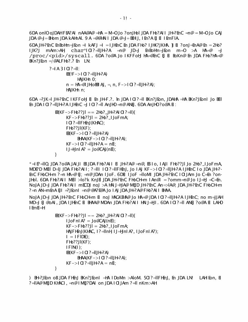
The tracing information as kept as a string in the proc structure. It is contained in a Procstuct member, char*syscalltrace and that information may be read at/proc/<pid>/syscall. The code to support reading it is found in the procreadfunction a/devproc.c in 9vx:
case Qsyscall:if(!p->syscalltrace)
return 0;n = readstr(offset, a, n, p->syscalltrace);return n;
The actual tracing support is in trap.c. In the syscall function, there are functions to fillin the syscalltrace string at syscall entry and exit. The entry code is:
if(up->procctl == Proc_tracesyscall){up->procctl = Proc_stopme;syscallprint(ureg);procctl(up);if(up->syscalltrace)
free(up->syscalltrace);up->syscalltrace = nil;startnsec = todget(nil);
}
Basically, the code tests if the process is traced and, if so, sets procctl to Proc_stopme,which will halt the process; calls syscallprint, to set up->syscalltrace string so the tracing program can read it; and then stop. This stop allows the tracing system to gain control. The process will block until the tracing program sends a command to start again.Note that the process might not be restarted with tracing enabled; the tracing programcan examine its actions and decide to set the traced process free.
Note that the tracing program is not required to read the syscalltrace string; no matterwhat it does, the string is freed when the process restarts. The syscall exit code is verysimilar:
if(up->procctl == Proc_tracesyscall){stopnsec = todget(nil);up->procctl = Proc_stopme;retprint(ureg, scallnr, startnsec, stopnsec);s = splhi();procctl(up);splx(s);if(up->syscalltrace)
free(up->syscalltrace);up->syscalltrace = nil;
}
A fraction of the print functions are shown below. Syscallprint, in the vx32 version, iscalled with uregs, and switches on the system call number:

14
static voidsyscallprint(Ureg *ureg){
uint32 *sp;int syscallno;vlong offset;Fmt fmt;int len;uint32 argp, a;
sp = (uint32*)(up->pmmu.uzero + ureg->usp);syscallno = ureg->ax;offset = 0;fmtstrinit(&fmt);fmtprint(&fmt, "%d %s ", up->pid, up->text);/* accomodate process-private system calls */
if(syscallno > nelem(sysctab))fmtprint(&fmt, " %d %#x ", syscallno, sp[0]);
elsefmtprint(&fmt, "%s %#ux ", sysctab[syscallno], sp[0]);
if(up->syscalltrace)free(up->syscalltrace);
switch(syscallno) {case SYSR1:
fmtprint(&fmt, "%08ux %08ux %08ux", sp[1], sp[2], sp[3]);break;
case _ERRSTR:fmtuserstring(&fmt, sp[1], "");break;
case BIND:fmtuserstring(&fmt, sp[1], " ");fmtuserstring(&fmt, sp[2], " ");fmtprint(&fmt, "%#ux", sp[3]);break;
There are a few problems with this approach. Fmtuserstring does reallocation. For several reasons, realloc is not supported in the 9k kernel. The use of uregs makes thiscode very architecture-dependent (which is why the code is in trap.c). The 9k version isrestructured and the code moved to port/:
________________Take it as a hint that one should not do reallocation

15
voidsyscallfmt(int syscallno, va_list list){
long l;Fmt fmt;void *v;vlong vl;uintptr p;int i[2], len;char *a, **argv;
fmtstrinit(&fmt);fmtprint(&fmt, "%d %s ", up->pid, up->text);
if(syscallno > nsyscall)fmtprint(&fmt, " %d ", syscallno);
elsefmtprint(&fmt, "%s ", systab[syscallno].n);
if(up->syscalltrace != nil)free(up->syscalltrace);
switch(syscallno){case SYSR1:
p = va_arg(list, uintptr);fmtprint(&fmt, "%#p", p);break;
case _ERRSTR: /* deprecated */case CHDIR:case EXITS:case REMOVE:
a = va_arg(list, char*);fmtuserstring(&fmt, a, "");break;
case BIND:a = va_arg(list, char*);fmtuserstring(&fmt, a, " ");a = va_arg(list, char*);fmtuserstring(&fmt, a, " ");i[0] = va_arg(list, int);fmtprint(&fmt, "%#ux", i[0]);break;
In the 9k version, the uregs struct is not visible. Rather, the function is set up as a syscall number and va_args. Most of the 9k system call tracing support is in the port directory, with limited impact on the architecture directories. For example, the architecture-dependent code for supporting the print looks like this:
syscallfmt(scallnr, (va_list)(sp+BY2SE));

16
Note the conversion of a very machine-dependent item � the stack pointer � to ava_list. This conversion is very simple on some architectures, and might be more complex on others.
The only other issue with tracing is to ensure that children of fork inherit the tracingflag, and that the syscalltrace buffer and procctl flag are cleared on exit. These changesare in newproc() and pexit() respectively and finding them is left as an exercise.
Tracing code: ratrace
For reasons of space we will discuss the code that traces by a given PID. The command-based code is little different, in that it forks a child and traces that child by PID.
The code sets up three channels, one for forks, one for exits, and one for process output. It keeps track of how many processes it is reading from and, when that count goesto zero, it exits. The basic setup code is then:
out = chancreate(sizeof(struct Str*), 0);quit = chancreate(sizeof(char*), 0);forkc = chancreate(sizeof(ulong *), 0);nread++;procrfork(writer, nil, 8192, 0);reader((void*)pid);
The �out� channel is for process output. It takes pointers to a Str struct, defined as:
typedef struct Str Str;struct Str {
char *buf;int len;
};
These structs are allocated by the producer (the reader thread) for process output andfreed by consumer (the writer thread).
The writer thread reads the three channels and does bookkeeping and output:

17
/* Catch exits */a[0].op = CHANRCV;a[0].c = quit;a[0].v = nil;/* Catch IO -- channel of pointers to a struct */a[1].op = CHANRCV;a[1].c = out;a[1].v = &s;/* Catch forks -- channel of ints so we know the PID */a[2].op = CHANRCV;a[2].c = forkc;a[2].v = &newpid;/* That is all */a[3].op = CHANEND;
for(;;) {switch(alt(a)){/* proc exited */case 0:
nread--;if(nread <= 0)
goto done;break;
case 1:/* output */fprint(2, "%s", s->buf);free(s);break;
case 2:/* proc forked */nread++;break;
}}
done:exits(nil);
}
The reader thread processes the output from the child processes, looking for rforkinstantiations that create a new process.

18
voidreader(void *v){
char *ctl, *truss;int pid, newpid;int cfd, tfd;Str *s;int forking = 0;
pid = (int)v;ctl = smprint("/proc/%d/ctl", pid);if ((cfd = open(ctl, OWRITE)) < 0)
die(smprint("%s: %r", ctl));truss = smprint("/proc/%d/syscall", pid);if ((tfd = open(truss, OREAD)) < 0)
die(smprint("%s: %r", truss));
cwrite(cfd, ctl, "stop", 4);cwrite(cfd, truss, "startsyscall", 12);
This setup gets the process into a traced state. The stop is only strictly necessary on thevery first reader that is invoked, but does no harm. The process is started and thenresumed, and will stop on the next system call.
The code sets up to read a buffer up to 8191 bytes (to ensure null termination) of an8192 byte buffer. The buffer is a Str, which is what is sent down the chan.
s = mallocz(sizeof(Str) + 8192, 1); /* The �+� is not a typo */s->buf = (char *)&s[1];
This snippet allocates contiguous memory, with the Str struct and its data. Then thecode simply hangs on reading the syscalltrace fd.
/** 8191 is not a typo. It ensures a null-terminated string.* The device currently limits to 4096 anyway*/
while((s->len = pread(tfd, s->buf, 8191, 0ULL)) > 0){if (forking && (s->buf[1] == �=�) && (s->buf[3] != �-�)) {
forking = 0;newpid = strtol(&s->buf[3], 0, 0);sendp(forkc, (void*)newpid);procrfork(reader, (void*)newpid, 8192, 0);
}
This code examines the system call return value, indicated by an �=� as the first character. The �forking� variableis set to 1 by the previous pass through this loop if the systemcall would create a new process. Hence: if the last system call should have created a newprocess; and this is a system call return, i.e. first byte is �=�; and it succeeded, indicatedby the third byte not being a �-� sign, i.e. the return value of the fork was not -1; thenwe need a new reader proc. The code then reads the pid and starts a new reader, while

19
also sending the new pid to the writer thread.
Catching forks is a bit tricky, this three part test has worked well:
/* There are three tests here to guarantee no false positives */if (strstr(s->buf, " Rfork") != nil) {
char *a[8];char *rf;rf = strdup(s->buf);if (tokenize(rf, a, 8) == 5) {
unsigned long flags;flags = strtoul(a[4], 0, 16);if (flags & RFPROC)
forking = 1;}free(rf);
}sendp(out, s);cwrite(cfd, truss, "startsyscall", 12);s = mallocz(sizeof(Str) + 8192, 1);s->buf = (char *)&s[1];
}
Once the process quits, reader sends an indication on the quit chan and exits.
sendp(quit, nil);threadexitsall(nil);
}
Limitations
There are a few remaining problems. We made a decision early on for non-printing characters to put a �.� in the output in place of the character. That was a mistake. Information is lost when the output is displayed. We need a better data format that shows morethan �.�. The �\xxx� format is not an obvious improvement; possibly symbols wouldwork.
Currently, we only show 32 bytes. The amount of data to be shown should be controllable via a write to the ctl file of a process. Interestingly, this limitation has not yet beena problem.
Tracing slows things down quite a bit. Is this a real problem? It is hard to make a strongcase either way.
Conclusions
Ratrace is a system call tracing system for Plan 9. There are two implementations, onefor vx32 and one for the 9k variant of the Plan 9 kernel. We have used ratrace to debugprograms and find problems with kernels. Because it presents the data to the user program as text, the nature of the information passed from kernel to user is very differentfrom existing tools for Unix, and as a result trace programs far smaller than its Unixcounterparts.

20
Acknowledgements
Russ Cox provided feedback and improved the vx32 version substantially. Jim McKiegreatly improved the implementation of ratrace now found in the 9k kernel. Noah Evanswrote the first version of the ratrace tool.

Recent Plan 9 Work at Bell Labs
Geoff [email protected]−labs.com
Bell LaboratoriesMurray Hill, New Jersey 07974
USA
ABSTRACT
Bell Labs recently ported Plan 9 to new systems with non-PC architectures. This is a status report on those ports and a summary of whathelped, what didn�t and what could.
1. Introduction
In my group of Plan 9 developers and users at Bell Labs in Murray Hill during the lasttwo years (2008�2010) or so, much of our work has been based on ports of Plan 9 tomachines other than the IBM PC. This talk will describe the ports, what we use them(or plan to use them) for, and what we learned.
As usual, the bulk of Plan 9 code is sufficiently portable that only the kernel needs tobe moved to a new system, and even that only involves populating a subdirectory of/sys/src/9 and possibly creating a bootstrap program in /sys/src/boot. Aport to a system for which we have no compiler and no similar kernel would requiresubstantially more work, as described in reference [6].
2. Non−PC Ports: Common Problems and Techniques
We ported Plan 9 to PowerPC 405, 440 and 450 machines and to ARM 926 andCortex-A8 machines. They all share certain classes of obstacles.
2.1. Memory Barriers and Caches
A fairly common memory architecture is a that store instructions queue data in a writebuffer in the processor, which is gradually drained to a first-level cache, then to alarger but slower second-level cache, and finally to DRAM. The IBM PC model providescache-coherent memory, so that we rarely have to worry about cache maintenance inthe PC port. Cache-coherent memory largely hides the speed tricks pulled by modernprocessors, which include aggressive caching through multiple levels of cache, andout-of-order (or delayed) memory stores and instruction execution. Even on the PC,we still occasionally have to execute data or instruction barrier instructions by callingcoherence to ensure that previous instructions and memory stores have completed; forexample, in the implementation of locks (to accelerate notification of other processorstrying to acquire the lock), and before or after DMA transfers.
By contrast, the PowerPC has long exposed the above processor tricks to the programmer, and ARM processors are now catching up (alas). So in the ports that I have done,partly out of paranoia, I was fairly heavy-handed in the use of barrier instructions toavoid surprises. Now that the ports are up and running, some of those barriers arebeing removed and kprof has been helpful in finding hot spots due to barriers.
The full sequence of operations needed to guarantee that a write to memory address

22
addr has completed (or at least is visible to all peripherals and other processors) inthese systems is:
" an instruction barrier, to force the store instruction to complete
" a data barrier, to flush the data from the processor�s memory write buffer to level 1(L1) data cache (or memory if uncached)
" flush addr�s level 1 data cache line to the level 2 (L2) cache, if any
" flush addr�s level 2 data or unified cache line to RAM or further cache levels
This sequence could have to be extended in future to additional levels of cache. (TheARM v7 architecture cache control registers permit eight levels of cache!) The fullsequence is only needed for cached (actually write-back cached) memory, and deviceregisters are mapped as uncached, so they only require the barrier instructions toensure that stores have completed. Cache lines are often 32 or 64 bytes long.
In a few cases, for example after DMA input, it�s necessary to invalidate cache linesrather than flushing them.
Whenever possible, we�ve configured caches to be write-back for maximum speed.
We imported USB code from the PC port to the ARM ports and had to first add barriersand cache flushing to it. The USB in-memory data structures maintained partly by theUSB drivers and partly by the host controllers are currently allocated from uncachedmemory because managing the caches in the presence of such mixed data structureswas too hard: consider a data structure, the first part maintained by hardware, the second maintained by software, and the boundary between them is not a cache-lineboundary, yet the data structure is required by hardware to be aligned to a power of 2.
2.2. Kernel Memory Mapping
In the Virtex and ARM ports, the maximum physical memory was 512MB or less(though not always starting at physical address zero), so by mapping the kernel base(KZERO) to virtual addresses 0x80000000 (PowerPC), 0xC0000000 (TI OMAP35system-on-a-chip (SoC)) or 0x60000000 (Marvell Kirkwood SoC), we are able toaddress all of physical memory from the kernel using trivial versions of kmap andkunmap, unlike the PC kernel, which is mapped at virtual 0xF0000000 yet needs tobe able to address up to 3.75 GB of memory using kernel virtual addresses (thoseabove KZERO). The different bases were chosen to permit various devices to beidentity-mapped for simplicity.
2.3. Kernel Debugging
The Virtex and IGEPv2 boards include a normal Intel-8250-compatible serial port anda few LEDs under software control, which simplifies initial porting and debugging. TheARM boards other than IGEPv2 have combined JTAG and serial ports with special cableswith a USB connector at the other end. usb/serial now knows how to drive theseports and there are MS Windows drivers too.
On the ARM ports we have enabled hardware watchdog timers so that if the kernelgoes off the rails, the system will reset itself, thus returning control to U-boot. (DasU−boot is a �universal� open-source boot loader derived from Linux and often providedas the stock boot loader on non-PC systems.) There is similar code in the Virtex ports,but it�s currently turned off because resetting the Virtex boards is less useful.

23
2.4. ARM Kernel Initialisation
U-boot just lays the kernel�s image down in memory, without regard for segmentboundaries, so the ARM kernels relocate their data segments to the expected physicaladdresses and then zero their BSS segments.
We use U-boot to load /cfg/pxe/$ether into memory before loading the kernel,which parses the in-memory copy to simulate what 9load would have done on the PC.
U-boot configures the processor and various SoC devices before loading the kernel,which is a help because there are many, many figurative dials and knobs (thousands ofpages worth) that can be tweaked and sometimes must be just to get basic functionality. Our kernels make an effort to configure the hardware that they use, but probablydon�t do the full job. Time is finite but hardware configuration registers and pad andgpio configurations are not (or so it seems).
2.5. Floating Point and Other Emulation
The Xilinx Virtex and Marvell Kirkwood boards have no floating-point units, so the kernel traps and emulates floating-point instructions. This is necessary becausefloating-point is used in awk, for example.
The ARM ports will also emulate ldrex, strex and locally-invented cas instructions if theprocessor traps them as illegal instructions.
2.6. Math Debugging
We used a port of W. M. Kahan�s paranoia to watch for errors in floating-point emulation. A new program to verify vlong arithmetic found a code-generation bug in qcwhich has since been fixed.
3. PowerPC Ports
These PowerPC ports are all CPU server kernels.
3.1. Blue Gene Ports
This work is being funded by the U.S. Dept. of Energy (DoE) under the project name�HARE�* and the main participants are Bell Labs, IBM Research, Sandia National Labsand Vitanuova. The intent is to provide full operating system capabilities via comparatively lightweight Plan 9 rather than heavyweight Linux or even more primitive operating systems on very large-scale parallel machines.
The Blue Gene machines are many-core PowerPC systems from IBM with multiple coressharing memory on a single board, and many boards in a complete system, connectedvia Ethernet and several types of networks developed by IBM specifically for the BlueGene machines. Processor clock rates are typically modest (e.g., under 1GHz) toreduce power consumption and heat dissipation. Floating-point instructions differfrom the usual PowerPC instructions. The complete system can be partitioned intoindependent clusters of power-of-2 boards. All the cores of a single cluster are initially loaded via JTAG with the same kernel image and all started synchronously atonce.
The systems we have developed on are at Argonne National Lab. The environment is________________* Portions of this project supported by the Department of Energy under Award NumberDE-FG02-08ER25847.

24
very much geared to batch processing, so interactive development is a bit odd, and oursessions are limited to at most an hour of elapsed time on the development machine.
An initial port to the BG/L (with 64K PowerPC 440 cores) was done, but current work ison the larger BG/P (with 160K PowerPC 450 cores) and will probably move eventuallyto the still larger BG/Q (with at least 750,000 PowerPC 460(?) cores) being built now byIBM. Drivers for the various IBM networks have been written. We�ve done some workon more aggressive 9P caching of infrequently-changed files with user-mode servers;the details are reported elsewhere at this workshop.5 IBM has granted permission toexport a snapshot of the BG/P Plan 9 port, and it can be extracted with one of thesecommands:
hg clone http://bitbucket.org/ericvh/haregit clone http://git.anl−external.org/plan9.git
Note that this is not a stock Plan 9 kernel but is an internal development kernel variantnamed 9k.
3.2. Virtex 4 and 5 Ports
The Xilinx Virtex 4 FX and 5 FXT evaluation boards are FPGA-based systems with PowerPC processors (300MHz 405D5X212 and 400MHz dual-issue 440X5,13, 7 respectively). They have L1 caches but no L2 caches. We did these ports to demonstrate thefeasibility of an idea for a hardware device to be used in embedded systems. The twoevaluation boards are similar and the Virtex 5 port is a minor variant of the Virtex 4port and uses many of its source files. It would be awkward to combine them into asingle port because the low-level details of traps and memory management differbetween the PowerPC 405 and 440.
The PowerPC 405D5X2 errata list was long and worrying but we were able to workaround most of the hardware bugs. The 440X5 had a much shorter and less worrisome errata list.
3.2.1. Virtex Bootstrapping
An FPGA is a Field-Programmable Gate Array. A giant Xilinx CAD tool crunchesthrough a VHDL definition of your specific �hardware� design for 30�60 minutes,downloads the generated bit-stream, which includes the static RAM contents, into theFPGA, and starts it running by taking the PowerPC(s) out of reset. The normal PowerPCrestart sequence sets the PC to the last word of memory (static RAM in this case) andbegins execution.
Thus we need to include a stripped-down 9load bootstrap program in the static RAMcontents (128K bytes) of the bit-stream loaded into the FPGA. 9load loads a Virtexkernel, /power/9vt[45]cpu, over Ethernet via BOOTP and TFTP and jumps to it.Since bootstrapping via downloaded bit-stream and 9load is relatively slow and difficult to trigger remotely, /dev/reboot and #ec were implemented and debuggedearly, which allowed us to reboot at will, even remotely. We carried this forward intothe ARM ports too, though U-boot is more tractable than the Virtex boot process.
The Virtex 5 can be configured to have two PowerPC cores, but its caches are per-processor and not maintained coherently, so coordinating the two cores is painful andour existing symmetric multiprocessing code isn�t sufficient. If configured for twocores, Plan 9 currently puts the second one to sleep. Ideally, it would be nice to usethe second core to run the rather dumb Ethernet controller.

25
3.2.2. Virtex Performance
These PowerPCs have only 64 translation lookaside buffers (TLBs) in their memorymanagement units (MMUs), and that number is dropping fast in newer PowerPCdesigns, so we now round segments on the power architecture up to 1MB multiples,which will allow us to use pages larger than 4K bytes and thus take fewer page faultsand need to reload the TLBs (in software) less often.
Both boards use a complicated combination of DMA engines, hardware FIFOs (byte orword queues) and Ethernet controller, which just doesn�t go very fast. Sometimes theDMA engines aren�t much faster than copying the bytes with memmove, and usingthem complicates the Ethernet driver. We do use the DMA engines in the Virtex ports.These ports are noticeably slower than the Marvell Kirkwood port and not just becausethe processors are slower. We consistently used as our benchmark building the Kirkwood kernel on quiescent diskless machines with their root file systems on our mainfile server:
cd /sys/src/9/kw# 2nd mk will have file system caches loaded{ mk clean; mk; mk clean; time mk } >/dev/null
(Note that the mkfile links the kernel twice: once with symbols and once without.) Onthe Virtex 5 over gigabit Ethernet, this reports:
44.32u 35.60s 99.80r mk # virtex 5 gb
Small level 1 caches and the lack of a level 2 cache are likely responsible for its overallslowness.
For comparison, this is how long it takes on our main four-core 2.5 GHz Core 2 XeonPC CPU server using gigabit Ethernet:
2.26u 2.46s 4.01r mk # quad xeon pc gb
on a one-core 2.2 GHz AMD K8 PC terminal using gigabit Ethernet:
2.95u 2.34s 8.31r mk # amd k8 pc
and a 500 MHz Soekris net5501-70 AMD Geode LX 586 PC CPU server using 100Mb/sEthernet:
20.78u 11.42s 49.48r mk # 586 pc 100mb
3.2.3. Virtex Port Availability and Desirability
Anyone who wants one of the Virtex ports should mail me. Note too that new VirtexFPGA designs (e.g., Virtex 6) use ARM processors rather than PowerPC processors.
4. ARM Ports
These ARM ports are all CPU server kernels so far, though there is work in progress toconvert some of the ARM systems into terminals too.
The ARM systems that we ported to all come with U−boot as their boot loader, but eachvendor customises it, so each instance of U-boot behaves differently, though most canboot via PXE (BOOTP and TFTP) eventually. The Beagleboard�s U-boot doesn�t evenallow PXE booting over USB Ethernet, so it typically is booted from an SDIO memorycard, which makes testing new kernels painful.
The most useful by-product of the work with ARM Cortex-A8 processors may be thatwe will be closer to driving Cortex-A9 multi-core processors or other v7 architecture

26
ARM systems when they appear.
4.1. OMAP35: Beagleboard
We started porting Plan 9 to the Beagleboard with the intent of using it as a small,portable terminal that could boot quickly (i.e., without the IBM PC�s power-on self-test). The processor is a 500 MHz dual-issue ARM v7-a architecture3 chip (theCortex-A8)4 with L1 and L2 caches. The board costs US$149, though that includes nocables, no case, and no power supply. By the time you finish adding peripherals,powered USB hub(s), power supply, and cables, it�s not so portable (or cheap). Theboard includes a serial port and (complicated) video controller. We now have a driverfor this video controller, based on a first draft by Per Odlund.
Unfortunately the Texas Instruments (TI) OMAP 3530 SoC8 that the Beagleboard is builtaround was designed for cell-phone or similar battery-powered operation and is quitecomplicated and somewhat buggy. Its biggest defect is that it lacks a built-in Ethernetinterface. In principle we could use USB Ethernet (disgusting though it is) but wehaven�t got the 3530�s USB to work yet (and there are some nasty-looking USB-relatedbugs in the 3530 errata list). As a result, the Beagleboard isn�t really usable yet.
The Cortex-A8 processor includes VFPv3 floating-point hardware, but the kerneldoesn�t yet save and restore FPU registers and other state during a context switch.That�s okay for now because 5c doesn�t yet generate VFP op-codes for floating-pointinstructions, but rather op-codes for the old ARM 7500.
4.1.1. IGEPv2 and Gumstix Overo
Meanwhile, we bought an IGEPv2 board from ISEE in Barcelona. The IGEP is also builton the 3530 SoC and is supposed to be quite similar to the Beagleboard except that itadds some external devices such as 100Mb/s Ethernet via the SMSC 9221.11 Also, theCPU can be run at 720 MHz rather than 500 MHz, and our port does so. We run thesame kernel on the Beagleboard, the IGEPv2 board and the 600 MHz Gumstix OveroEarth, which also provides the SMSC 9221 Ethernet controller but is based on theOMAP 3503 (not 3530) SoC. Unlike the Kirkwood, we haven�t got access to the NANDflash memory to work yet; it�s not well documented. At least on the IGEP board wehave in the Unix Room, plugging in a DVI cable disables the Ethernet controller, so theIGEP may never be usable as a terminal. The Gumstix don�t have this problem.
Ordering the IGEP from Spain and getting it through US customs was a challenge; Idon�t recommend buying one lightly if you are in North America. The Gumstix shouldbe easy to obtain instead.
4.1.2. OMAP35 Performance
Unfortunately, the rudimentary 9221 Ethernet controller is somewhat like the VirtexEthernet controller, and thus consumes enough system time to make the IGEP fairlyslow. Currently we do not use DMA but rather programmed I/O to copy data betweenmain memory and the Ethernet FIFOs, which simplifies the driver compared to usingDMA. Running our benchmark on the IGEP and Gumstix over 100Mb/s Ethernet yields:
24.58u 30.07s 70.65r mk # igep 100mb28.88u 38.38s 81.67r mk # gumstix overo 100mb

27
4.2. Kirkwood: Sheevaplug, Guruplug and OpenRD
The other ARM ports were going slowly and we noticed the early advertising for theSheevaplug, based on Marvell�s Kirkwood SoC (88F6281),10, 9 for US$100. The processor is a 1.2 GHz ARM v5 architecture1 chip (the ARM 926EJ-S)2 with L1 and L2 caches.The SoC is more tractable than the OMAP35 SoC, though still somewhat tedious to initialise. The Guruplug is particularly interesting because it has two gigabit Ethernetinterfaces (and RJ45 connectors), and thus might make an interesting firewall or othernetwork device, or a server of some kind (e.g., secure store in flash memory), possiblystandalone.
All of these systems run the same kernel. We started with the Inferno Kirkwood port,which helped us get going. We have got most of the parts that we care about working,including access to flash memory and even the bizarre cryptographic accelerator.
4.2.1. Kirkwood Performance
The integral Marvell 1116 gigabit Ethernet controller autonomously performs DMA inand out of buffer rings, so the port is fairly zippy and quite usable:
16.66u 8.39s 31.44r mk # guruplug gb
5. The Legendary AMD64 PC Port
One port that we haven�t done much work on lately is the amd64 port. For a start, it�sbased on a non-stock kernel (9k) better suited to 64-bit machines. For example, ituses varargs to extract system call arguments. The initial target was AMD K8 systemsfor DoE work several years ago and the port is a minimal CPU server kernel. The DoEwork changed direction and there has been little development of the port since.
It does not run 386 binaries. Some Ethernet controllers (mostly higher-performanceones) and UARTs have drivers, typically imported from the Plan 9 PC port. Thesethings do not yet work: audio, video, USB, floppies, disks, and laptop stuff such asPCMCIA. Some of this will be easy to import but it would be nice to take the opportunity to drop legacy support for old devices and processors when importing. However,video will be painful: the kernel either has to run the VESA BIOS in 16-bit real mode oremulate it.
Using this port also requires 6[cal] and libmach amd64 support, and a modified 9load,all of which exist.
6. Performance Summary
Table 1 summarises the above time(1) output lines sorted by user-mode time, slowestfirst, and adds other system characteristics. Of these systems, only the Virtex 5 lacksan L2 cache. The �issue� column is the claimed maximum number of instructions thatmay be issued per clock cycle. Machines above the middle dividing line have Ethernetcontrollers that don�t use buffer rings.
A few observations: the sub-GHz dual-issue machines are the slowest in our sample.The slowest machines all have clumsy DMA/FIFO/Ethernet combos and the fastest allhave Ethernet controllers that use buffer rings and initiate DMA autonomously (notethe variation in system times).

28
times name cpu MHz Ethernet issue_____________________________________________________________________44.32u 35.60s 99.80r virtex 5 400 1Gb 228.88u 38.38s 81.67r gumstix overo 600 100Mb 224.58u 30.07s 70.65r igep 720 100Mb 2_____________________________________________________________________20.78u 11.42s 49.48r 586 pc 500 100Mb 116.66u 8.39s 31.44r guruplug 1,200 1Gb 12.95u 2.34s 8.31r amd k8 pc 2,200 1Gb 12.26u 2.46s 4.01r quad xeon pc 2,500 1Gb 2_____________________________________________________________________
Table 1: Performance Summary
7. Hardware Documentation
Documentation for the Virtex parts was uniformly better than for the ARM parts,largely because IBM wrote a lot of the PowerPC documentation. Xilinx�s contributionswere less clear, with fine points sometimes ignored. So for the Virtex ports, it wasusually possible to suspend disbelief, trust the documentation and get things to work.
7.1. ARM Documentation
The ARM ports are another story. There are at least three reference manuals neededfor each port: the processor architecture manual from ARM, the processor manual fromARM (and sometimes another from the SoC vendor), and the SoC manual from Marvellor TI. The latter two types of manuals point to the earlier manual(s) for specifics. Forexample, the SoC manual will point to the processor manual for details of how the processor does something, and it in turn will point to the corresponding architecture manual to describe a common mechanism. If you�re lucky, the board manufacturer willinclude some board documentation too.
The architecture reference manuals from ARM have been getting better: more preciseand complete, less slippery. The CPU and SoC technical reference manuals, however,combine extreme verbosity with imprecision, incompleteness, bugginess and a generallack of rigour that is maddening. There is a tendency to write ��this register is used todo X��, without explaining how or why.
One ends up flipping between the three or four manuals, and the OMAP35 manualalone is a single PDF file of 3,500 pages, so having a good PDF viewer is essential.3,500 pages should be enough to describe almost anything, yet it�s incomplete; quitean accomplishment. The table of contents, figures and tables alone is 160 pages long.
Perhaps separate programmers� reference manuals are needed.
7.2. Poor SoC Design and Documentation
The SoC manuals are particularly poor. The SoCs themselves appear to have beenslapped together from existing intellectual property that the companies had lyingaround, without much thought for how they might be used together, and the manualsreflect this: each chapter describes a separate standalone device. The manuals appearto be written for other hardware designers or implementors and make many assumptions about background knowledge. There is little coherent explanation of why thissack of components was slung together or what the interconnections are or how youmight need to use them to do something, such as access the flash memory or drive thevideo or Ethernet controller.
There is a great deal of low-level explanation of the tedious games of �Mother-may-I�

29
that one must play to even get the hardware to function. For example, clocks have tobe enabled, because they aren�t always already enabled. Until they are enabled,accessing some device registers causes address faults. Also, various parts of the SoCshave to have their power turned on. At least one SoC has internal �firewalls� that haveto be disabled or subverted. In general, the hardware doesn�t come up in a sane stateand U-boot doesn�t always fix that (though it does leave some things in a sane state).Failing that, the documentation ought to contain a concise and complete list of exactlywhat steps are required to initialise a particular device.
7.3. Marvell Documentation
A drawback of using the Kirkwood SoC is that Marvell seem to regard almost all oftheir manuals as proprietary. Given their low quality, Marvell may just be trying toreduce their embarrassment. Alcatel-Lucent has a non-disclosure agreement withMarvell, but even with that, we are not able to get all the documentation we need.Contrary to Marvell�s belief, Linux (or U-boot) drivers are not a substitute for goodhardware documentation (nor for understanding!), but we have sometimes had toresort to reading them.
7.4. Board Documentation
Global Technologies fabricated the Sheevaplug, Guruplug, etc. ISEE in Barcelona madethe IGEPv2 board, and the Beagleboard was an open-source hardware project. TheBeagleboard documentation is pretty thorough. The IGEPv2 documentation is lessthorough, specifically when covering access to flash memory (which differs from theBeagleboard�s) and the devices added to the stock Beagleboard, notably Ethernet. Global Technologies have done a pretty good job of documenting the plugs, though theSheevaplug is better covered than the Guruplug.
8. Lessons Learned and Recommendations
8.1. Kernel Debugging
Effort to connect the various JTAG interfaces (via USB) to db or acid would likely pay offwhen the processor mysteriously goes away. Even just having U-boot print theprocessor�s state at the instant that U-boot regained control would help.
Debugging can be assisted by having a dead-simple variant of iprint that will alwayswork, including before the interrupt controller is initialised, in interrupt-service routines, and when interrupts are masked.
A little debugging code in /sys/src/9/port/portclock.c can diagnose infinite loops caused by incorrect implementation of the clock primitives. An added testin /sys/src/9/port/xalloc.c can detect a cycle in the Hole list and avoid aninfinite loop.
8.2. Hardware Sanity (or Lack Thereof)
There is a great market opportunity for someone to build a (cheap) sensible general-purpose ARM system with good documentation, since there appear to be none now.
Hardware cache coherency helps correctness and performance, especially in multiprocessor systems.
The performance of an Ethernet controller (as dictated by its design) can determine theusability of a Plan 9 port. We should be past the era of programmed I/O and FIFOs and

30
separate DMA engines, and kludges like Ethernet via USB, for Ethernet controllers. Allfuture Ethernet controllers should perform DMA to and from buffer rings without needing host intervention to initiate each packet transfer. It�s not necessary to have all thefeatures of the Marvell 1116, which goes somewhat overboard, though. Also, gigabitEthernet is pretty cheap now and ought to be standard.
Hardware should come out of reset in a sane and usable state.
Hardware documentation should include system programmers as part of the intendedaudience, and should be public, complete, clear and concise. GPIO (general-purposeI/O) pins and similar ill-defined bits, and their uses, need to be documented in greatdetail at the CPU, SoC and board levels to avoid the finger-pointing so often seen inexisting manuals, which makes it maddeningly difficult to pin down exactly what mustbe done to get some device to work. In general, comments like �see your board documentation for specifics� are unhelpful unless the board documentation actually doesdescribe simply and directly what�s needed. Too often these pointers are just cop-outs, with no one taking responsibility for getting all the necessary information published. The sort of treasure hunt that we undertook to determine the IRQ number andmemory address for the I/O registers of the IGEP�s 9221 Ethernet controller should nothave to be repeated.
9. Acknowledgements
Salva Peiró and Mechiel Lukkien ported native Inferno to the Kirkwood SoC.
Rae McLellan helped me decrypt voluminous yet often unhelpful hardware documentation. He and Claudia Collyer provided useful comments on drafts of this paper.
These ports were made feasible by the existing Plan 9 PowerPC and ARM compilersuites, and made easier by existing Plan 9 kernels for other PowerPC and ARM systems.
10. References
1. ARM, ARM Architecture Reference Manual, DDI 0100I, 2005.
2. ARM, ARM926EJ−S Technical Reference Manual, DDI 0198E, 2008.
3. ARM, ARM Architecture Reference Manual, ARM v7−A and ARM v7−R edition, DDI0406B, 2008.
4. ARM, Cortex−A8 Technical Reference Manual, DDI 0344J, 2009.
5. Geoff Collyer Charles Forsyth, ��A Cache to Bash for 9P,�� Fifth International Workshop on Plan 9, Seattle (October 2010).
6. Bob Flandrena, ��Adding Application Support for a New Architecture in Plan 9,�� inPlan 9 Programmer’s Manual, Fourth Edition (April 2002).
7. IBM, PPC440x5 CPU Core User’s Manual, Preliminary, SA14-2613-03, July 15,2003.
8. Texas Instruments, OMAP35x Applications Processor Technical Reference Manual,SPRUF98D, October 2009.
9. Marvell, Unified Layer 2 (L2) Cache for Sheeva" CPU Cores Addendum, MV-S104858-00, Rev. B, September 28, 2008.
10. Marvell, 88F6180, 88F6190, 88F6192, 88F6280, and 88F6281 Integrated Controller Functional Specifications, MV-S104860-00, Rev. E, September 17, 2009.

31
11. SMSC, High−Performance 16−bit Non−PCI 10/100 Ethernet Controller with Variable Voltage I/O, LAN9221 datasheet Revision 2.6, 12-04-08.
12. Xilinx, PowerPC Processor Reference Guide, UG011 (v1.2), describes 405D5, January 19, 2007.
13. Xilinx, Embedded Processor Block in Virtex−5 FPGAs Reference Guide, UG200(v1.6), describes 440X5, January 20, 2009.

A Cache to Bash for 9P
Geoff Collyer
Bell LaboratoriesMurray Hill, New Jersey 07974
[email protected]−labs.com
Charles Forsyth
Vita Nuovawww.vitanuova.com
ABSTRACT
We needed to reduce the load on the file server shared by thousands ofnodes in a Blue Gene Plan 9 cluster. Plan 9 had two existing cachingmechanisms for 9P file servers: a volatile cache controlled by devmnt,and a persistent disk-based cache managed by the user-level server cfs.Both sent the server all 9P requests except reads satisfied by the cache.Cfs was quickly converted to a ramcfs that used the large memory of aBlue Gene I/O node instead of a disk, but most 9P traffic still passedthrough. A redesign produced fscfs, which breaks the direct linkbetween its client�s 9P transactions and those it makes to the server,producing a dramatic reduction in traffic seen by the server.
Introduction
As part of a project1, 2 exploring alternatives in distributed systems infrastructure onultrascale platforms, we ported Plan 9 from Bell Labs3 to several models of IBM�s BlueGene system. Blue Gene4 comprises up to 65,536 compute nodes and 1,024 I/Onodes, which are partitioned into processing sets (or psets). Each pset has an I/O nodeproviding system services to up to 64 compute nodes. Only the I/O nodes are connected to an external Ethernet. Each node on the Blue Gene/P model has 4 PowerPCprocessors. Nodes have no permanent storage except a tiny NVRAM. All storage forprograms and files is provided by external file servers, accessed by the I/O nodes viaEthernet, and accessible to the CPU nodes only via a specialised network connectingthem to the I/O nodes.
In our experimental environment, we run Plan 9 throughout, with different configuration and initialisation for CPU nodes and I/O nodes. Lacking a native Plan 9 file serverat the Blue Gene site, we serve files from a Linux server running hosted Inferno.5 Allnodes boot with a built-in file system paqfs(4) that provides a limited set of files forbootstrap.
Originally, each I/O node imported a full file system from the Inferno service on Linux,bound it into a more elaborate name space used by our model for distributed computation,6 and made that composite name space available to its CPU nodes usingexportfs(4). Consequently every non-local file access performed at a CPU node wasforwarded by the I/O node to the file server. It was obvious that having all nodes ultimately send all file service requests directly or indirectly to a single Plan 9 file server

33
would be slow, but we wanted to focus on developing our model of computation,before worrying about making it efficient. Unfortunately, as we ran experiments oneven modest configurations, it became clear that the naive structure led to failures,and an unusable system. In particular, the Linux server ran out of file descriptors withonly a few hundred nodes, but to be fair even a native file server would run short ofsome resource eventually. To compensate, we could the replicate the file systemacross many servers, but all the requests � and the data � would still traverse thesame network.
There is an alternative structure that can scale with the number of nodes: it arrangesthe nodes into a tree. We can then avoid transmitting redundant copies of the data byintroducing caching into the tree.7 We can further avoid needless duplication of filesystem operations across all nodes by caching the results of a given set of operationsfor later use if that set recurs.
Underlying assumptions and requirements
Plan 9 is running on many thousands of nodes, supporting a few scientific computingprograms for a given run. The programs are typically a few megabytes, and increasingly require a collection of supporting system files, not just Plan 9 executables, butthe libraries for scripting languages such as Perl or Python. Such shared files are read,not usually written; files that are written are unlikely to be shared concurrently. Writerequests are uncommon. Big data files consumed or produced by the application aremanaged by another service, for instance through channels provided by the clusteringsoftware.6 During both initialisation and subsequent phase changes of an application,system call traces show that similar sets of commands and file accesses are executedon all CPU nodes, sometimes at nearly the same time.
Although initially we would build the caching structure explicitly, the design shouldallow extension to support a truly hierarchical cache, perhaps using some ideas fromEnvoy.7
9P
First, a quick review of relevant aspects of the 9P protocol. A file server in Plan 9 isany program that implements the server side of the file service protocol, 9P.8 A 9Pclient sends a request to a 9P server and receives a reply. A 9P server is passive: itgenerates no message except in response to an explicit request from the client. Eachrequest has a tag that numbers the request, an integer type that denotes the desiredoperation, and a set of parameter values for the operation. Parameters can be integers, strings, byte arrays, and structured values such as Qid and Dir. The position andtype of each parameter is completely determined by the operation type. There are novariants. Replies have a similar structure. The reply to a request has a tag equal to thetag of the request, a type derived from the request type, and a set of results thatdepends on that type. Alternatively, a server can respond to any request with an errormessage. (Tags allow the server to satisfy I/O requests out of order, although thatdoes not happen here.)
Authentication data is carried as opaque data exchanged using Tread and Rreadrequests through a special fid established by a Tauth request. Thus, only the endpoints need to know the formats and content of the authentication data.
Because the message formats are simple and completely defined, and authenticationdata is handled cleanly, one can easily write a variety of services that act as

34
intermediaries to 9P conversations. In particular, a caching service can simply interpose itself on a 9P connection. The design of any 9P caching service is driven by considering the desired response to the requests in the protocol, in much the way that acompiler design is driven by the abstract syntax of its language. They are listed inTable 1.________________________________________________________________________________________________Tversion tag msize version start a new session
Tauth tag afid uname aname optionally authenticate subsequent attaches
Tattach tag fid afid uname aname attach to the root of a file tree
Twalk tag fid newfid nwname nwname*wname walk up or down in the file tree
Topen tag fid mode open a file (directory) checking permissions
Tcreate tag fid name perm mode create a new file
Tread tag fid offset count read data from an open file
Twrite tag fid offset count data write data to an open file
Tclunk tag fid discard a file tree reference (ie, close)
Tremove tag fid remove a file
Tstat tag fid retrieve a file�s attributes
Twstat tag fid stat set a file�s attributes
Tflush tag oldtag flush pending requests (eg, on interrupt)________________________________________________________________________________________________
Table 1 9P requests
Existing caching support
Plan 9 has long included the cache file system cfs, a user-level file server interposedon the connection between a Plan 9 client and a remote file server. It caches file dataon a local disk, to reduce latency. It intercepts all 9P exchanges on the connection.Most messages are sent on unchanged, but it adds any file data it sees to the cache,and satisfies file reads from the cache if possible. The cache is write-through, so thecached data is never more recent than the server�s. Files and file data are both kept ona least-recently-used basis, up to the size of the disk partition allocated to the cache.Cfs uses the Qid value returned by each open to detect and discard out-of-datecached data. The cache persists on a disk partition between boots, but because thecache is write-through it can simply be reformatted if invalid.
In the Fourth Edition, Plan 9 acquired a kernel-level cache. It is an optional kernelcomponent, although it is usually configured. It must also be explicitly enabled, by theMCACHE option of the mount system call, because it changes the semantics of accessto file structures synthesised on the fly, including devices and services such asupasfs(4). If present and enabled, it will cache data from files served by that mount.Unlike cfs, the cache resides in physical memory pages, and the cache is lost onreboot. Otherwise it is similar: client reads are satisfied from the cache if possible;data exchanged with the server through read and write will be added to the cache; filesand data are managed least-recently-used; and out-of-date cache entries are detectedusing the Qid value returned by open. The cache pages are only briefly mapped intothe kernel address space when accessed, reducing the pressure on the kernel addressspace, and only a limited amount of data per file can be cached, to help constrain thephysical memory dedicated to the cache.

35
Ramcfs
Ramcfs was the first attempt at mitigating the problem. It was created by changing acopy of cfs to use a region of memory as its cache rather than a region of disk. Unlikecfs, ramcfs initialises the cache each time it starts, since there is no persistent storage.We added a −r option that declares that all the files are unchanging (readonly) andthus may be cached more aggressively. On boot, each IO node would first insertramcfs on its connection to the central file server. Thus, the subsequent access by theI/O node�s CPU nodes would pass through the cache on the I/O node.
Ramcfs had its own disadvantages. It always reserved a big chunk of memory, to makea virtual block device. Since the cache runs on I/O nodes not CPU nodes, that does notlimit the memory available to a computation, but it was still a bit of a hack. More seriously, because ramcfs was based on cfs it also forwarded all requests involving metadata to the remote server.
Fscfs
Existing components were inadequate, so we implemented a new one, fscfs that notonly caches data, but reduces the number of operations seen by the file server. Likecfs and ramcfs, it acts as a write-through cache for data, but when many processes aremaking identical file system requests over time, it effectively aggregates them into single requests at the server. This has a dramatic effect. Table 2 shows statistics measured at a single IO node. (The values on the other IO nodes in the run were similar.)The interval is from the initial connection to the file server up to the point where theCPU nodes had started all their network services and were ready for duty. The tablegives the number of various file system operations seen by the IO node, as producedby its 64 CPU node clients, and the number of operations it had to send on to theserver. The final row shows the number of bytes read by all clients, and the number ofbytes read from the server and cached at the IO node to satisfy the client readrequests. The difference is dramatic. The reduction in load seen by the server willalso be magnified by the addition of each new IO node and its cluster.
_______________________________________Op IO node Server
Tversion 1 1Tattach 1 1Twalk 7,855 56Topen 1,486 77Tread 6,823 133Tclunk 4,749 0Tstat 4,224 4,224
bytes read 19,913,992 462,722_______________________________________
Table 2 Statistics from fscfs on an IO node with 64 CPU nodes.
Design and implementation
Fscfs is a normal, user-level C application, using libthread for internal concurrency. Like cfs, it is a 9P transducer: it acts as a client to a remote 9P file server on oneconnection, and acts as a 9P server to its client on another connection. (Once that connection is mounted in the name space, many client processes can share it.) To providedata caching, fscfs uses the same strategy as the existing caches: it makes a copy of

36
data as it passes through in either direction, and stores it in a local cache. SubsequentTread requests for the same data will be satisfied from the cache. Twrite requestsare passed through to the server, replacing data in the cache if successful. Cacheddata is associated with each active file, but the memory it occupies is managed on aleast-recently-used basis across the whole set of files. When a specified threshold forthe cache has been reached, the oldest cached data is discarded.
Unlike the existing caches, however, fscfs handles more 9P requests itself without delegating them to the server. Those requests include Twalk, Topen, and Tclunk.(Support for Tstat has since been added, and is not reflected in the results.)
To do that required two significant changes from previous schemes. We explain themby reference to several internal data types, shown concisely below:
IOmode :: R | W | RWFid :: fid: u32int qid: Qid path: Path opened: SFid mode: IOmodeSFid :: fid: u32int
Path :: name: string qid: Qid parent: Path kids: set of Path (Valid | Invalid)Valid :: sfid: SFid file: optional FileInvalid :: reason: string
File :: open: IOmode¦SFid dir: Dir clength: u64int cached: sparse array of Data
First, fscfs separates its client from the server, by managing two sets of fids. One setis allocated by its client, as before; those are seen only by fscfs, which remembersthem in values of the Fid type. The other set of fids is allocated and controlled byfscfs; only those fids are seen by the server. It records them in SFid values. Second,using the distinction between fid sets, fscfs caches the results of walks and opens.The distinction allows a cached fid (known to the server) to outlive a fid allocated bythe client. It also allows several client fids to share a single server fid. That alonereduces the resource requirements at the server as the number of client referencesgrows.
From each Tattach referring to a file server�s tree, fscfs grows a Path tree representing all the paths walked in that tree, successfully or unsuccessfully. A successful walkresults in an end-point that records the SFid referring to that point in the server�s hierarchy. (Note that intermediate names need not have server fids.) If a walk from agiven point failed at some stage, that is noted by a special Path value at that point inthe tree, which gives the error string explaining why the walk failed. If a subsequentTwalk from the client retraces an existing Path, fscfs can send the appropriateresponse itself, including failures and walks that were only partially successful. Ifnames remain in the walk request after traversing the existing Path, fscfs allocates anew SFid for the new Path end-point, sends the whole request to the server, andupdates the Path appropriately from the server�s response. Remembering failures is agreat help when, for instance, many processes on many nodes are enumerating possible names for different possible versions of (say) Python library files or sharedlibraries, most of which do not exist. (It would be more rational to change the software not to do pointless searches, but it is not always possible to change componentsfrom standard distributions.)
When a file or directory has been opened, the corresponding Path will have a File structure. It stores the SFid(s) for each mode (read, write, read/write) with which a clienthas opened the file, the currently known file length, and any data cached for that file.The File�s SFid is distinct from that in the Path because the latter might later be walked

37
elsewhere, and it is illegal to walk an open fid. Furthermore, files can anyway beopened simultaneously with different modes, each needing a distinct fid on the serverto carry the correct mode.
Files in Plan 9 can also be opened �remove-on-close� (ORCLOSE). As a special case,the client Fid for such a file will be given its own unique SFid on open, to ensure thatthe timing of the remove remains the same from the client�s point of view. The file willbe removed when that particular client closes it.
Some requests update the file system: Twrite, Tcreate, Topen (with OTRUNC),Twstat, and Tremove. Those are delegated to the server, and on success the localstate is updated to match. In other words, the Path and File caches are write-through.For instance, a successful Twrite request will add the data written to the cache. Asuccessful Tcreate will extend the current Path tree, possibly replacing a previousInvalid entry for the newly-created name, and then open a new SFid for the file. Amore subtle case is Tremove, which always frees any existing sfid for the file, asrequired by remove(5), but only on success does it mark the file as removed in the Pathtree and discard any cached data.
Fscfs always delegates operations on certain types or classes of files to the server,specifically authentication files, append-only, and exclusive-use files. Currently it alsodelegates Topen and Tread for directories, because read(5) does not allow a seek ina directory except to the start. We are currently changing the software to cache thewhole directory on the first read, so that directory reading does not provoke excessiveload on the file server.
Discussion and further work
There is no great mystery about implementing a cache for a file system, whetherdirectly in a kernel, as with the UNIX buffer cache, or by intercepting a file service protocol, as with NFS or 9P. Even so, there are typically some subtle points.
Fscfs is just over 2,000 lines of C code, including some intended for future use. It hasmore than satisfied our initial requirements, although much more can be done. Itaggregates common operations in a general but straightforward way. Its Path cache issimilar to Matuszek�s file handle cache in his NFS cache,9 and closer to 9P home, someof the subtle cases in fid handling in fscfs seem to turn up in the implementation of 9Pin the Linux kernel, where Linux lacks anything corresponding exactly to a fid.10
Currently, as is true in our environment, fscfs assumes that the client requests alwaysrepresent the same user. Removing that assumption requires growing separate Pathtrees from distinct Tauth and Tattach instances, to ensure that errors (eg, �permission denied�) are reported in the correct context. Instead of having a Path referdirectly to a File, the Path would record only the Qid, and the File would be found in aQid to File map, to ensure cached data is correctly shared and updated.
More interesting additions would be to make our file system access fault-tolerant andmore efficient. Given the structured nature of our target networks and systems, oneattractive approach is to use a variant of random trees, which could also provide loadspreading.11 Outside our peculiar environment, we also intend to experiment withinterposing fscfs between a client and a 9P service that uses a cloud-based storagesubsystem such as Amazon�s S3.

38
Acknowledgement
This work has been supported by the Department of Energy project Holistic Aggregated Resource Environment (�HARE�) under Award Number DE-FG02-08ER25847.
References
1. Ronald G Minnich, Matthew J Sottile, Sung-Eun Choi, Erik Hendriks Jim McKie,��Right-weight kernels: an off-the-shelf alternative to custom light-weight kernels,��ACM SIGOPS Operating Systems Review 40(2), pp. 22-28 (April 2006).
2. Ron Minnich, Jim McKie, Charles Forsyth, Latchesar Ionkov, Andrey Mirtchovski, EricVan Hensbergen Volker Strumper, ��Rightweight Kernels,�� FastOS PI Meeting and Workshop, Santa Clara, California, http://goo.gl/UgFx (June 2007).
3. Rob Pike, Dave Presotto, Sean Dorward, Bob Flandrena, Ken Thompson, HowardTrickey Phil Winterbottom, ��Plan 9 from Bell Labs,�� Computing Systems 8(3), pp. 221-254 (Summer 1995).
4. A Gara, M A Blumrich, D Chen, G L-T Chiu, P Coteus, M E Giampapa, R A Haring, PHeidelberger, D Hoenicke, G V Kopcsay, T A Liebsch, M Ohmacht, B D Steinmacher-Burow, T Takken P Vranas, ��Overview of the Blue Gene/L system architecture,�� IBMJournal of Research and Development 49(2-3), pp. 195-212 (2005).
5. The Inferno Programmer’s Manual, Vita Nuova Holdings Limited (2000).
6. Eric Van Hensbergen, Noah Paul Evans Phillip Stanley-Marbell, ��A unified executionmodel for cloud computing,�� ACM SIGOPS Operating Systems Review 44(2), pp. 12-17(April 2010).
7. R G Ross, ��Cluster storage for commodity computation,�� UCAM-CL-TR-690, University of Cambridge Computer Laboratory (June 2007).
8. C H Forsyth, ��The Ubiquitous file Server in Plan 9,�� Proceedings of the Libre Software Meeting, Dijon, France (2005).
9. Stephen Matuszek, Effectiveness of an NFS cache, http://goo.gl/UgFx.
10. Eric Van Hensbergen Ron Minnich, ��Grave Robbers from Outer Space: Using9P2000 Under Linux,�� Proceedings of the USENIX 2005 Annual Technical Conference,FREENIX Track, pp. 83-94, USENIX (2005).
11. David Karger, Eric Lehman, Tom Leighton, Rina Panigrahy, Matthew Levine DanielLewin, ��Consistent hashing and random trees: distributed caching protocols for relieving hot spots on the World Wide Web,�� Proceedings of the twenty−ninth annual ACMsymposium on Theory of Computing, El Paso, Texas, pp. 654-663 (1997).

HTTP−Like Streams for Plan 9
John Floren ([email protected])Ron Minnich
Andrey Mirtchovski
Rochester Institute of TechnologyRochester, NY
ABSTRACT
In Plan 9, all file operations, whether local or over the network, takeplace through the 9P file protocol. Although 9P is both simple and powerful, developments in computer and network hardware have over timeoutstripped the performance of 9P. Today, file operations, particularlyreading and copying files over a high-latency network, are much slowerwith 9P than with simpler protocols such as HTTP or FTP. In an effort toimprove the speed of 9P, the ability to stream files across the network ina manner similar to that of HTTP will be implemented in 9P.
Motivation
Transferring a large file over the Internet via 9P can be a frustrating experience. WhenPlan 9 was written, files were smaller, most of the users were on a fast internal network, and people were used to computers being a bit slow anyway. Today, of course,files have gotten larger in general and transfers are much more likely to take placeacross the country or around the world. In these conditions, 9P is significantly slowerthan HTTP or FTP, requiring a noticeably longer amount of time to transfer a file.
9P is an RPC system; if a program calls read(), it blocks until the message gets sentacross the country, processed by the remote computer, and replied to. cp callsread() over and over when copying a file; each time it wants to get a chunk (8 KB ata time), it must wait for the entire ping-pong latency time of the connection before itreceives the data, writes it to the destination file, and gets the next chunk.
HTTP, on the other hand, takes an extremely simple-minded approach to data transfer.A request is sent to the server, the server sends back the entire file to the client, theclient processes the file at its leisure.
We thought it would be instructive to transfer some large files over links with realisticlatency, comparable to Internet latencies. Two Plan 9 systems were set up with a Linuxgateway between them; the gateway could add any amount of latency desired. The 9Pnumbers were obtained by mounting the file server�s root and timing how long it tookto copy a remote file to /dev/null ( cp, not fcp, was used for the measurements). The HTTP numbers were collected by having one system runningip/httpd/httpd and calling hget on the other system, redirecting the output to/dev/null. The same randomly-generated files were used for each test. Theresults are shown in Tables 1 and 2.

40
__________________________________File Size 9P HTTP__________________________________10 MB 29.57 s 14.08 s50 MB 147.44 s 70.81 s100 MB 296.06 s 140.38 s200 MB 590.94 s 281.63 s__________________________________
Table 1, 15 ms RTT___________________________________File Size 9P HTTP___________________________________10 MB 76.16 s 19.43 s50 MB 374.07 s 98.88 s100 MB 747.13 s 197.90 s200 MB 1512.31 s 400.00 s___________________________________
Table 2, 50 ms RTT
In tests for 10, 50, 100, and 200 megabyte files, 9P takes about twice as long as HTTPwith a 15 ms RTT, and around four times as long for 50 ms RTT. Copying a 200 MB filetakes over 25 minutes with 9P, but less than 7 minutes with HTTP. A 50 ms RTT is notunusual for the Internet�at the time of writing, the RTT from New York to Californiawas about 87 ms. Clearly, plain 9P is not ideal for transferring files over wide-area networks.
Streams
Copying an entire file is an extremely common operation that displays the latencyproblem well. The source for cp is only 177 lines. It simply reads some bytes from thesource file, writes them to the destination, and repeats. It�s an entirely sequentialoperation�if bytes 0-99 have just been read, the next bytes requested will be100-199 and so on.
Since sequential file reading is very common and a prime victim of the latency problem, we decided to try extending 9P�and therefore the programmatic file I/Ofunctions�to specifically handle sequential reads. Rather than read in a whole file bysending lots of Tread messages and waiting for the Rreads, we want to be able tosend a single Tstream and get an arbitrary number of Rstream messages back,each carrying a chunk of the data.
_________________________________________________Client Server_________________________________________________
Tstream tag fid offsetRstream tag count dataRstream tag count data
îRstream tag 0 0_________________________________________________
Table 3, sample streaming session
Table 3 shows the typical exchange of messages between client and server. Triggeredby a stream() system call, the client sends a Tstream which contains a tag, a fid,and an offset. Upon receiving the message, the server begins sending many Rstreamreplies, each containing a tag, the number of bytes of data, and a chunk of data. Whenthe file has been exhausted, the server sends a message with 0 bytes of data. The datasent in the Rstream messages remains in the client�s buffers until sread() is called,

41
which consumes part of the stream.
Previous efforts at improving performance over low-bandwidth, high-latency networkshave focused largely on transparency�see the Op protocol, for example, or simplyconsider the use of caching. We decided to move away from that; a programmer shouldknow when a file will be read in sequentially and can thus decide when to use streamsor when not to use streams. Since streaming will not modify the way existing file operations work, old code will not require modification, but new programs can take advantage of streaming if desired.
For most people, all the world�s a TCP connection. Given that, we�ve taken some liberties in the design of the Tstream/Rstream messages. Since everything is guaranteed to show up, and in order, there are no sequence numbers inside the messages.Rstream messages can be allowed to remain on the connection�s read queue untilthe program calls sread() and they are consumed. There is no need for flow control,because TCP has its own flow control built-in.
Implementation
The implementation of streams is in progress. As a first experiment, only reading fromstreams will be implemented; this is a common and easy-to-test situation.
Two system calls, stream(int fd) and sread(int fd, void *buf,long nbytes) will be added; stream sets up a stream on an open file and has the9P server start sending data. sread is used to read a portion of the received data.
The devmnt device will also be modified to handle stream requests. Since remote fileaccess is handled by devmnt, it is the obvious choice for modification, but any otherkernel devices could also be modified to accept streams.
Getting a program to take advantage of streams will be a two-part process. First, 9Pservers (such as fossil ) must be re-written to handle streams. Then, the programitself ( cp or mp3dec, for instance) must be re-written to perform sequential readingusing streams. To test the streams system, fossil and cp will be modified to handlestreams.
Caveats
Outside of the confines of testing, compatibility will be an issue. For instance, supposea streams-enabled cp attempted to copy a file from a non-streaming fileserver. cpwould send a Tstream message, but the server would not recognize it�a Rerrorwould be returned. Luckily, this problem should be easy to avoid by making streamand sread more devious. If a stream request is met with an error, a flag can be setwhich causes sread to behave in a compatibility mode, issuing a normal Treadwhen called rather than reading from streamed data.
Conclusion
Properly implemented, streams should allow programmers to sequentially read (andeventually write) files more effectively while still maintaining compatibility with oldersoftware. By using streams in appropriate places, we hope to make 9P a much morecompetitive and realistic method for transferring files, performing backups, and simplyusing a remote filesystem.

Effective Resonant Frequency Tracking With Inferno
Jeff Sickel ∗ and Paul Nordine !
Corpus Callosum Corporation, Evanston, IL 60202 USA.! Physical Property Measurements, Inc., Evanston, IL 60202 USA.
� Author for correspondence ([email protected])
ABSTRACT
We describe a digital technique for tracking the resonant frequencies ofpiezoelectric transducers used to drive an aeroacoustic levitator.Realtime sampling of the voltage and current phase difference is usedin a lowpriority feedback loop to control drift and stabilion.
The implementation leverages 9p on embedded 16bit dsPIC33F digitalsignal controllers. Data collection and processing are performed withvarious 9p clients. This paper describes the use of 9p and Inferno totrack, adjust, and optimize output frequency and sound pressure levelson the instrument.
11. Introduction
The process of developing a new aeroacoustic levitator (AAL)[1] provided an opportunity to solve a persistent problem in prior versions: the six independent piezoelectrictransducers, used to create standing waves that provide levitation, position, and spincontrol, would drift out of resonance. The transducers have wellmatched resonant frequencies at ambient temperature, within ±10Hz in 22,000 Hz. But as they warm upwhen operated, the resonant frequencies change at rates dependent on the transducerQfactors, the desired output sound pressure level (SPL), and differences in the piezoelectric material properties. The range of resonant frequencies may increase such thatit becomes impossible to maintain equal and constant SPL values from all six transducers. As a transducer goes off resonance at constant voltage operation, the currentdecreases and the currentvoltage phase difference changes. The SPL changes proportionally to the currentvoltage phase off of resonance. A constant SPL is maintainedusing a feedback loop to monitor the resonant and operating frequency difference andadjusting the output voltage to the acoustic amplifier.
A previous generation of the AAL used a piezoelectric film pickup attached to a regionon the reverse side of the transducer horn. The pickup provided reference signals forthe output frequency and amplitude of the horn. The sensor output was highly sensitive to placement. Correctly placing and securing the film proved problematic, to thepoint that driving the transducer to high SPL values required for solidliquid phase transition stabilization tended to separate the film from the horn.
Prior runtime protocols required user monitoring of the transducer output levels andmanually selecting one transducer as the �master� for tracking the frequency during anexperiment. The logic was to pick the transducer that would sweep up or past the resonant frequencies of the other transducers as its own resonant frequency dropped as itheated up. This action would work for short experiments but ultimately limited the

duration of levitation experiments due to SPL and frequency drift as the temperaturesof each transducer fluctuated.
The new system removes the user selection criteria by monitoring the voltage, current,and voltagecurrent phase difference of each transducer. The resonant frequencies aredetermined from the VI phase differences and the system is operated at their averagevalue. The SPL of each transducer attained by calculating the amplifier output power isadjusted to match a desired set point for the amplifier output voltage. The range ofresonant frequencies is controlled as the transducers warm up by simply turning thecooling fans on or off if the amplifier frequency is greater or less than the resonant values.
The new technique is implemented by sampling the output voltage and current on anembedded system, tracking phase differences between the current and voltage, thencontrolling the cooling fans and adjusting output gain and setting the operating frequency to the average resonant frequency. A remote program running in Inferno hasproven significantly simpler to model and implement, as the profiling data on eachtransducer is stored in a human readable file and can be easily updated as necessary.The enhanced adjustment and tuning capabilities provide optimal stabilization andsimple setup for tuning experiments.
Inferno was chosen as a front end for several reasons, most important being portabilitybetween platforms and the support for 9p (Styx)[2]. The programming languageLimbo[3] has proven a rapid tool for implementing floating point algorithms[4], andconcurrently scheduling measurement processes for running transducer profiling tests.
11.1. Resonance
Each acoustic transducer is composed of solid aluminum alloy with a piezoelectrictransducer as the driver designed for a resonant frequency between 22.12 and 22.25kHz[1]. Forced convection cooling is controlled by a Limbo program (a change fromprior versions; see implementation). The manufacturing process introduces certainvariations in the overall mass and characteristic profile of a transducer, resulting in avarying Qfactors. The subtle differences in physical characteristics cause each transducer to drift off resonant frequency differently as their temperature fluctuates overdifferent output voltages.
After assembly, each transducer is profiled by measuring sound pressure levels with acalibrated microphone at selected driving voltages and tracking change over time. Thedata are used to determine the Q of each transducer, the functional relationshipsbetween SPL and amplifier power, and the VI phase as it relates to theresonantoperating frequency difference. Closely matching transducers are paired onan axis. Three sets of transducers are then installed into the AAL on orthogonal axes,where further calibration testing is required. The profile data are stored in ahumanreadable file and used in the control program to track and measure SPL astransducers go on and off resonance. The use of separate files allows the user toquickly change configurations, as transducers are rearranged or changed out duringthe calibration phase of the instrument.

44
11.2. VoltageCurrent Phase Tracking
The voltagecurrent phase difference is used to determine how a transducer is beingdriven in comparison to its resonant frequency. When the transducer is off resonance,the output power of the constantvoltage amplifier decreases and an increased voltageis required to attain the desired SPL.
The controller boards paired with each acoustic transducer drive the output through anonboard DAC (Maxim MAX5353) and DDS (Analog Devices AD9834). The dsPIC33FADC channels are used to measure the output voltage and current. A Xilinx XC9536XLCPLD calculates return voltage and current phases and provides interrupts to a gatedtimer on the dsPIC33F. This timing data provides the leading or lagging phases of thecurrent to the voltage and is used as feedback into the control system.
12. Firmware Implementation
The main communication board uses the dsPIC33F serial UART module to present adevice command mode and direct 9p layering for interaction with Plan 9 and Infernodevelopment machines. 9p on the dsPIC33F was accomplished by porting lib9 andlib9p source from Plan 9 from User Space [5] to support the 16bit architecture of thedsPIC33F.
The communication board is configured to start the serial UART in a raw commandmode and will automatically switch to 9p by sniffing for a Tversion message[6] in theserial input stream. On receipt of the Tversion header, the UART driver switches to aDMA mode to reduce the UART receive interrupts on the dsPIC33F from one per byte totwo DMA interrupts: a fourbyte size field, and the remaining message length. Thisencapsulation of 9p simplified the code required for error checking and recovery.
12.1. Application Programmers Interface
The cluster of embedded controllers is accessed through a single serial interface. AnIOLAN device server is used to extend the 9p connection1 over the network. 1 AnIOLAN device server is configured to only allow one connection at a time. Though thecluster can be accessed directly without using the 9p protocol, the majority of the functionality has been implemented by leveraging the file system provided over 9p. TheAAL communications controller provides a singlelevel file system that is accessedthrough a shell or program. The file system and underlying single level structure isportrayed in Figure 1.
The ctl, data, stats, status files are used for direct access to the main communicationsboard. The t* files align to each transducer control board. As is typical in Plan 9, thectl file is used to send commands to the board. Reading the stats file dumpshumanreadable data for all the online boards as seen in the prior example. The datafile provides an array of bytes packed for each transducer row in the stats file. Thestatus provides information on the current state of the main communications board.End user programs can read the current state of the system by opening and readingthe stats file. Alternatively, individual board data can be read through the tN files, providing single channel monitoring and control. A read of the tNerr file returns and errorsummary tracked by the main control board for each card.
In practice, a scheduled read of the data or stats files is performed to update the inmemory representation of the AAL data. That data are used for any processing until

45
% mount −A tcp!iolan!aal9p /n/aal% lc /n/aalctl status t1err t2err t3err t4err t5err t6errdata t1 t2 t3 t4 t5 t6stats t1ctl t2ctl t3ctl t4ctl t5ctl t6ctl
% cat /n/aal/statsID Ai Fi Phi Mper Mfreq Flags Vo PhiV Io PhiI Ft1 2000 221677 3756 0 0.00 65 2221 0 1654 3151 0t2 2029 221677 2048 0 0.00 193 1982 0 1640 3275 0t3 2400 221677 0 0 0.00 65 2439 0 1538 3212 1t4 1655 221677 2048 0 0.00 193 2636 2938 1294 0t5 2031 221677 0 0 0.00 65 2044 0 1691 3075 0t6 1866 221677 2048 0 0.00 65 2372 0 1724 3295 1
Figure 1 Inferno mount command and AAL file system access.
the period ends and a subsequent read has been performed.
12.1.1. Ctl commands
The main communication board and six transducer controller boards can be controlledwith a simple set of commands. Writing a string to the ctl file either produces a globalchange or a change along an axial pair of boards as described in Table 3.
fb N Enables �1� or disables �0� position feedback processing onall transducer control boards.
freq N Globally set frequency to N dHz.gain N Globally set the DAC gain to N. Linear from min 3584 to
max 512.reset Reset transducers to default output values.spin str str N Change spin of X, Y, or Z axis �up� or �down� N (DDS 0-4096
� 0-360 degrees.)
Table 3 Communication board ctl commands.

46
12.1.2. Transducer ctl commands
Changes to independent boards are handled through the t?ctl files as depicted inTable 4. The specified transducer commands are used to tune the output during a running experiment. They can also be used for custom applications that test a particulartransducer.
debug N Enables �1� or disables �0� debugging output over externalUART.
fan N Turn transducer cooling fan on �1� or off �0�.fb N Enables �1� or disables �0� position feedback processing.freq N Set frequency to N dHz (use main ctl instead).gain N Set channel output DAC gain to N.mod N n Amplitude modulate N (±100) % at n Hz.phase N Set DDS phase to N (DDS 0-4096 � 0-360) degrees.reset Reset to startup values.
Table 4 Transducer ctl commands
13. Modeling
The file system representation of our AAL controller boards allowed us to create simpleshell scripts or programs to provide quick data collection and analysis. For example,the use of an rc script to scan the transducers and collect data for testing furtheraspects of our control loop can be seen in Figure 2.
log = $home/tests/gainfreqsweep.logecho Start ‘{date} >> $logecho reset > ctl
for(g in ‘{seq 3000 −20 2400}) {echo gain $g > ctlfor(f in ‘{seq 221500 10 222500}) {echo freq $f > ctlecho gain: $g freq: $fcat stats >> $log
}}
echo reset > ctlecho Completed ‘{date} >> $log
Figure 2 Example of a gain and frequency sweep.

47
The transducer controller boards do not sample the output from the amplifiers directly.We manually verify the linear output for voltage and current and use those data to construct a calibrated profile set of constants used in subsequent equations. The calibration procedure is also performed with a simple Rc function and manual entry as in Figure 3.
log = $home/tests/run.logfn s {
ts = ‘{date −n}ID=‘{echo t$1}delta=‘{echo $2}PkV=‘{echo $3}PkI=‘{echo $4}measure=‘{cat $ID}Ai=‘{echo $measure | awk ’{print $2}’}Fi=‘{echo $measure | awk ’{print $3}’}Vo=‘{echo $measure | awk ’{print $8}’}PhiV=‘{echo $measure | awk ’{print $9}’}Io=‘{echo $measure | awk ’{print $10}’}PhiI=‘{echo $measure | awk ’{print $11}’}echo $ts $ID $Ai $Fi $Vo $PhiV $Io $PhiI $delta $PkV $PkI >> $log
}
cd /n/aalecho freq 221900 > ctlecho gain 2920 > t6ctl
# record transducer 6 measurements# delta in µs# ouput voltage and current recorded in volts from a scopes 6 7.2 2.98 .184
Figure 3 Rc data collection function and commands.
13.1. Equations
The data read from the data and stats files is in integer format. All floating point conversion is done in Limbo. A table of calibrated profile data is used with the measureddata from our calculations. The following equations use measured and set values fromTable 5.
Vo ADC 12bit measured voltage output to transducer.Io ADC 12bit measured current output to transducer.F Integer representation of frequency in dHz.Vg 12bit value written to the DAC.φV CPLD calculated 12bit voltage phase.φ I CPLD calculated 12bit current phase.Fosc dsPIC33F system clock, 7.378×10⁷
Table 5 Measurable input and output from transducer controller.
Calibration constants from our profile are: AV, A I, B I, D I, A φ, B φ, A SPL, AG, BG.

48
The first step is to calculate the amplifier output voltage, described by
V = AV ·Vo, (1)
where V is the calculated peak-to-peak voltage supplied to the transducer. The measured output voltage Vo is used with a calibration constant AV defined through priorprobed experiments.
The calculated current delivered to the transducer is
I = A I Io2 + B I ·Io + D I (2)
with I the calculated current, Io is measured output current, and the profile calibrationconstants are A I, B I, and D I. If a transducer is swapped out, or we need to changeadditional hardware, we can easily calculate new profile constants as required to fit thelinear range used when running the system.
The measured currentvoltage phase difference in amplifier output is determinedthrough
φC = Sign(φ I − φV ) ·1 −
Fosc·2
(φ I + φV )_________ ·ω·180 (3)
The frequency, ω, is reported in kHz with resolution determined by the DDS in decihertz. The result from equation 3 will be corrected in equation 4 to accommodate fora phase shift induced in our electronics. We can use φC without adjustments to thedata collected from each transducer in order to depict differing resonant frequencies ata fixed output gain as seen in Figure 4.
22.15 22.2 22.25
��� ¡¡¡
æææ×××∆+∆+
t1 æ
t2 ¡
t3 ×t4�t5 +t6 ∆
. . . . . . . . . . . . . . . . . . . . . . . . . . . . . . . . . . . . . . . . . . . . . . . . . . . . . . . . . . . . .
. . . . . . . . . . . . . . . . . . . . . . . . . . . . . . . . . . . . . . . . . . . . . . . . . . . . . . . . . . . . .
. . . . . . . . . . . . . . . . . . . . . . . . . . . . . . . . . . . . . . . . . . . . . . . . . . . . . . . . . . . . .
-90
-45
0
45
90
Figure 4 Plot of measured voltagecurrent phase difference. The frequency sweep was performed at a fixed gain, showing the resonant frequency variation across all six transducers.
To accomodate for a phase shift introduced in our electronics, a true VI phase difference correction is performed,
φ = φC + B φ (4)
Amplifier power, P, in units based on peaktopeak V and I measurements is defined as
P =100
V·I_____ ·cos(φ) (5)

49
The division by 100 is the result of our analysis using a V measurement with a 10:1probe and reporting I in ma.
The power required to match a specified SPL, measured in volts from a Bruel & Kjærpressure-field microphone located 7.5cm from the transducer surface, is
SPL = A SPL · �P , (6)
P = (A SPL
SPL_____ )2 (6.1)
The new gain values are calculated by
VC = AG ·G + BG, (7)
where the G value is a gain parameter supplied by the end user or the software duringthe feedback loop.
The new voltage for a specified SPL are
V2 = V�VC ·IC
V2 ·I2_______ , V2C = VC�VC ·IC
V2 ·I2_______ (8)
and then fed back to calculate a new gain value to write to the DAC. The process isrepeated at a defined interval in a thread running in our Inferno application.
The prior equations are implemented in Limbo and reduce into the following Limbofunction:
splgain(spl: real, tp: ref Tprofile, ts: ref Tstats): real{
ng := 0.0;V := math−>fabs(ampvolt(tp, ts));P1 := math−>fabs(amppower(tp, ts));if(P1 != 0.0) {
P2 := math−>fabs(splpower(spl, tp));V2 := V * math−>sqrt(P2/P1);Vc2 := V2/tp.Av;ng = (−tp.Bg + Vc2)/tp.Ag;
}return ng;
}
Figure 5 Limbo function used to attain a linear 12bit gain value. Thechange is performed by writing the new gain to the transducer controller ctl file.
The resonant frequency of a transducer is calculated using constants A3 to A0 in acubic equation relating frequency to VI phase difference,
ω r − ω = A3 φ3 + A2 φ2 + A1 φ + A0, (9)
where ω r is the resonant frequency and ω is the operating frequency.

50
14. Inferno control system
The prior algorithms are easily implemented in a Limbo module to handle all calibration routines required for the running system. In order to optimize the system, we usea timer to periodically poll the /n/aal/data file of the AAL and use the data to updatethe operating frequency and match pre-amp gain required to achieve the desired SPLvalues for each transducer. The timer callback uses the calculated average of resonantfrequencies determined through the result of equation 9.
By measuring the VI phase difference, the tracking algorithm is used to tune the system under varying loads. The cooling fans for each transducer are turned on or off ifthe operating frequency is greater or less than the resonant frequency. This automated control brings the transducers into a ±10 Hz range from the operating frequency. The result of this control is that the resonant frequencies converge towardsthe operating frequency as the transducers warm up, as illustrated in Figure 6.
-10
-5
0
5
10
22.13
22.14
22.15
22.16
0 2000 4000 6000
æ
æ
æ
æ
æ
æ
ω æ
ω r − ωHz
ωkHz
Figure 6 Frequency tracking 0.9 SPL over time in seconds. The leftaxis depicts the ability to keep transducer resonant frequency ω r,within 10 Hz of the operating frequency ω. The right axis presents thedrop of the operating frequency.
The control system allows for fast startup times where we can quickly bring all sixtransducers into a working state from a cold start. Evidence of this is detailed in Figure 7 where we plot a period where the tracking system is not in operation.
Once the frequency and SPL tracking system is enabled, the transducers are broughtinto a manageable range as we can see in Figure 8. Though there is automated controlof the system, an operator can easily change parameters that effect SPL, sample position, spin while monitoring the Inferno console and performing visual inspection of thegas flow rate, temperature, and position of the sample.
14.1. Console
Most of the tasks used in controlling the system are performed within the user console. By default these are simple functions spawned off after mounting the AAL filesystem. The console provides the operator with simple management tools to set theSPL, operating frequency, phase relationships for position and spin control, and amplitude modulation. It also provides a simple graphically driven mechanism to turn SPLand frequency tracking or off and enabling position feedback processing used to stabilize a sample.

51
22.18
22.19
22.2
22.21
æ¡
∆
�
+×
æ¡
∆
�
+×
æ¡
∆
�
+×
æ¡
∆
�
+×
æ¡
∆
�
+×
æ¡
∆
�
+×
æ¡
∆
�
+×
æ¡
∆
�
+×
æ¡
∆
�
+×
æ¡
∆
�
+×
æ¡
∆
�
+×
æ¡
∆
�
+×
æ¡∆
�
+×
0.55
0.6
0.65
0.7
0.75
æ
¡
∆
�
+×
æ
¡
∆
�
+×
æ
¡
∆
�
+
×
æ
¡
∆
�
+
×
æ
¡
∆
�
+
×
æ
¡
∆
�
+
×
æ
¡
∆
�
+
×
æ
¡∆
�
+
×
æ
¡∆
�
+
×
æ
¡∆
�
+
×
æ
¡∆�
+
×
æ
¡∆�
+
×
Figure 7 Frequency and SPL tracking off. The left and right sides coverthe same time period of twenty minutes with the frequency a constant22.2065 kHz and the SPL set to 0.7. On the left, the six transducersresonant frequencies drift lower as they heat up over time. On theright, the actual SPL for each transducer varies as the voltagecurrentphase difference changes.
22.17
22.18
22.19
22.2
æ¡∆
�
+×
æ
¡∆
�
+×
æ¡∆
�
+
×æ¡∆
�
+
×æ¡∆
�
+
×
0.55
0.6
0.65
0.7
0.75
æ
¡∆�+× æ
¡∆�+×
æ
¡∆�+× æ
¡∆�+×
Figure 8 Frequency and SPL tracking turned on and run for approximately 10 minutes. The left shows the average frequency droppingfrom 22.1888 to 22.1823 kHz. On the right, the SPL stabilized at thetarget output of 0.7.
The graphics applications that define the console are currently made up of four separate screens: the primary console, a graphical scope, a statistics screen, and a positionsensor screen. These screens are used to manage the system as well as provide logging data of the statistics collected during the runtime.
15. Conclusion
The use of a 9p based file system has facilitated the creation of a working interface tothe AAL that allows easy user manipulation without requiring additional physical controls. By providing a single level file system with easy to understand commands wehave been able to provide a structure for quickly bringing the system up and monitoring its state. The ease of using Limbo programs or other shell environments to accessthe system has improved our ability to conduct experiments and gather data requiredfor further analysis that have historically been more difficult to accomplish.

52
16. Acknowledgements
We would like to thank Steve Finkleman, Eduardo Lopez Gil, Dennis Merkley, and JamesRix for their efforts in designing and developing the AAL.
17. References
[1] J.K. R. Weber, D. S. Hampton, D. R. Merkley, C. A. Rey, M. M. Zatarski, and P. C. Nordine.Aeroacoustic levitation: A method for containerless liquidphase processing at high temperatures.Review of Scientific Instruments, 65(2):456-465, February 1994.
[2] R. Pike, and D. M. Ritchie, The Styx Architecture for Distributed Systems. Bell Labs TechnicalJournal, 5(2), April-June 1999.
[3] D. M. Ritchie, "The Limbo Programming Language", in Inferno Programmer’s Manual, Volume Two,Vita Nuova Holdings Ltd., York, 2000.
[4] E. Grosse. Real Inferno. In Proceedings of the IFIP TC2/WG2.5 working conference on Quality ofnumerical software, p.270-279, January, 1997, Oxford, United Kingdom.
[5] R. Cox. Plan 9 from User Space. http://swtch.com/plan9port/
[6] http://plan9.bell-labs.com/magic/man2html/5/0intro


![Apple ][ Emulation on an AVR Microcontroller Emulation ... · Apple ][ Emulation on an AVR Microcontroller Emulation eines Apple ][ auf einem AVR Mikrocontroller Maximilian Strauch](https://img.dokumen.tips/doc/110x75/5d494b4588c99334058bd1f6/apple-emulation-on-an-avr-microcontroller-emulation-apple-emulation.jpg)