Embed Size (px)
Citation preview

© 2010 Kepware Technologies
KEPServerEX V5 Help

KEPServerEX V5 Help1
Table of Contents
................................................................................................................................... 61 Getting Started
.......................................................................................................................................................... 6KEPServerEX 5
.......................................................................................................................................................... 6Introduction
.......................................................................................................................................................... 6System Requirements
.......................................................................................................................................................... 7Server Summary Information
................................................................................................................................... 82 Standard Features
.......................................................................................................................................................... 8Interfaces and Connectivity
.......................................................................................................................................................... 9Components
.......................................................................................................................................................... 10Process Modes
................................................................................................................................... 103 Administration
.......................................................................................................................................................... 10Accessing the Administration Menu
.......................................................................................................................................................... 11User Management
......................................................................................................................................................... 11User Manager
......................................................................................................................................................... 12User Properties
.......................................................................................................................................................... 13Settings
......................................................................................................................................................... 13Settings - Administration
......................................................................................................................................................... 13Settings - Configuration
......................................................................................................................................................... 14Settings - Runtime Process
......................................................................................................................................................... 15Settings - Runtime Options
......................................................................................................................................................... 16Settings - Event Log
......................................................................................................................................................... 17Settings - Host Resolution
................................................................................................................................... 184 Tag Management
.......................................................................................................................................................... 18Tag Management
.......................................................................................................................................................... 19Automatic OPC Tag Database Generation
.......................................................................................................................................................... 22System Tags
.......................................................................................................................................................... 29Property Tags
.......................................................................................................................................................... 30Statistics Tags
.......................................................................................................................................................... 32Modem Tags
.......................................................................................................................................................... 35Communication Serialization Tags
................................................................................................................................... 375 Communications Management
.......................................................................................................................................................... 37Communications Management
.......................................................................................................................................................... 37Modem Support
......................................................................................................................................................... 37Using a Modem in the Server Project
......................................................................................................................................................... 39Phonebook Tag
......................................................................................................................................................... 40Phone Number
................................................................................................................................... 416 Built-In Diagnostics
.......................................................................................................................................................... 41Built-In Diagnostics
.......................................................................................................................................................... 41OPC Diagnostics
......................................................................................................................................................... 41OPC Diagnostics Window
......................................................................................................................................................... 44OPC Diagnostic Events
.......................................................................................................................................................... 49Channel Diagnostics
......................................................................................................................................................... 49Channel Diagnostics
................................................................................................................................... 527 Basic Server Components
.......................................................................................................................................................... 52Basic Server Components
.......................................................................................................................................................... 52What is a Channel?
......................................................................................................................................................... 52What is a Channel?

2Contents
2
......................................................................................................................................................... 53Channel Properties - General
......................................................................................................................................................... 54Channel Properties - Communications
......................................................................................................................................................... 55Channel Properties - Network Interface
......................................................................................................................................................... 56Channel Properties - RTS Line Control
......................................................................................................................................................... 57Channel Properties - Modem
......................................................................................................................................................... 58Channel Properties - Write Optimizations
......................................................................................................................................................... 60Channel Properties - Ethernet Encapsulation
......................................................................................................................................................... 61Channel Properties - Device Discovery
......................................................................................................................................................... 62Channel Properties - Advanced
.......................................................................................................................................................... 63What is a Device?
......................................................................................................................................................... 63What is a Device?
......................................................................................................................................................... 64Device Properties - General
......................................................................................................................................................... 66Device Properties - Ethernet Encapsulation
......................................................................................................................................................... 67Device Properties - Timing
......................................................................................................................................................... 69Device Properties - Auto-Demotion
.......................................................................................................................................................... 70What is a Tag?
......................................................................................................................................................... 70What is a Tag?
......................................................................................................................................................... 70Tag Properties - General
......................................................................................................................................................... 72Tag Properties - Scaling
......................................................................................................................................................... 74Dynamic Tags
......................................................................................................................................................... 74Static Tags (User-Defined)
.......................................................................................................................................................... 75What is a Tag Group?
......................................................................................................................................................... 75What is a Tag Group?
......................................................................................................................................................... 75Tag Group Properties
.......................................................................................................................................................... 76What is the Alias Map?
......................................................................................................................................................... 76What is the Alias Map?
......................................................................................................................................................... 77Alias Properties
.......................................................................................................................................................... 78What is the Event Log?
......................................................................................................................................................... 78What is the Event Log?
......................................................................................................................................................... 78Event Log Display
......................................................................................................................................................... 79Event Log Page Setup
................................................................................................................................... 808 Designing a Project
.......................................................................................................................................................... 80Designing a Project
.......................................................................................................................................................... 81Running the Server
.......................................................................................................................................................... 81Starting a New Project
.......................................................................................................................................................... 82Adding and Configuring a Channel
.......................................................................................................................................................... 83Adding and Configuring a Device
.......................................................................................................................................................... 85Adding User Defined Tags
.......................................................................................................................................................... 88Adding Tag Scaling
.......................................................................................................................................................... 89Saving the Project
.......................................................................................................................................................... 90Testing the Project
.......................................................................................................................................................... 96Channel Wizard
......................................................................................................................................................... 96New Channel - Identification
......................................................................................................................................................... 96New Channel - Device Driver
......................................................................................................................................................... 97New Channel - Communications
......................................................................................................................................................... 98New Channel - Summary
.......................................................................................................................................................... 99Device Wizard
......................................................................................................................................................... 99New Device - Name
......................................................................................................................................................... 100New Device - Model
......................................................................................................................................................... 101New Device - ID
......................................................................................................................................................... 103New Device - Timing
......................................................................................................................................................... 103New Device - Summary
................................................................................................................................... 1049 Server Options

KEPServerEX V5 Help3
.......................................................................................................................................................... 104Server Options
.......................................................................................................................................................... 104Options - General
.......................................................................................................................................................... 105Options - Runtime Connection
................................................................................................................................... 10610 Configuring from FIX Applications
.......................................................................................................................................................... 106iFIX Signal Conditioning Options
.......................................................................................................................................................... 112Project Startup for iFIX Applications
................................................................................................................................... 11211 Project Properties
.......................................................................................................................................................... 112Project Properties - Identification
.......................................................................................................................................................... 113Project Properties - OPC DA Settings
.......................................................................................................................................................... 114Project Properties - OPC DA Compliance
.......................................................................................................................................................... 116Project Properties - DDE
.......................................................................................................................................................... 117Project Properties - FastDDE/Suitelink
.......................................................................................................................................................... 119Project Properties - iFIX PDB Settings
.......................................................................................................................................................... 120Project Properties - OPC UA
.......................................................................................................................................................... 122Project Properties - OPC AE
................................................................................................................................... 12312 How Do I...
.......................................................................................................................................................... 123How Do I...
.......................................................................................................................................................... 123Use DDE with the Server
.......................................................................................................................................................... 123Use NetDDE Across a Network
.......................................................................................................................................................... 124Use Dynamic Tag Addressing
.......................................................................................................................................................... 124Process Array Data
.......................................................................................................................................................... 125Create and Use an Alias
.......................................................................................................................................................... 127Use an Alias to Optimize a Project
.......................................................................................................................................................... 128Optimize the Server Project
.......................................................................................................................................................... 129Select the Correct Network Cable
.......................................................................................................................................................... 130Use Ethernet Encapsulation
.......................................................................................................................................................... 132Resolve Comm Issues When the DNS/DHCP Device Connected to the Server is Power Cycled
.......................................................................................................................................................... 132Allow Desktop Interactions
................................................................................................................................... 13213 Error Messages
.......................................................................................................................................................... 132Error Descriptions
.......................................................................................................................................................... 135Server Runtime Error Messages
......................................................................................................................................................... 135Server Runtime Error Messages
......................................................................................................................................................... 136'<driver name>' device driver was not found or could not be loaded
......................................................................................................................................................... 136'<server name>' Server Started
......................................................................................................................................................... 136'<server runtime>' successfully configured to run as a system service
......................................................................................................................................................... 137'<server runtime>' successfully removed from the service control manager database
......................................................................................................................................................... 137Attempt to add DDE item '<item name>' failed
......................................................................................................................................................... 137Attempt to add FastDDE/SuiteLink item '<tag name>' failed
......................................................................................................................................................... 137Attempt to add OPC Client item '<item name>' failed
......................................................................................................................................................... 138Attempting to automatically generate tags for device '<device name>'
......................................................................................................................................................... 138Auto generation for tag '<tag name>' already exists and will not be overwritten
......................................................................................................................................................... 138Auto generation produced too many overwrites, stopped posting error messages
......................................................................................................................................................... 138Channel diagnostics started on channel '<channel name>'
......................................................................................................................................................... 139Channel diagnostics stopped on channel '<channel name>'
......................................................................................................................................................... 139Completed automatic tag generation for device '<device name>'
......................................................................................................................................................... 139Configuration session assigned to '<user name>' as Default User has ended
......................................................................................................................................................... 139Configuration session assigned to '<user name>' demoted to Read Only
......................................................................................................................................................... 140Configuration session assigned to '<user name>' promoted to Write Access
......................................................................................................................................................... 140Configuration session started by '<user name>'
......................................................................................................................................................... 140Configuration TCP/IP port number changed to '<port number>'
......................................................................................................................................................... 140Data collection is '<enabled/disabled>' on device '<device name>'
......................................................................................................................................................... 141DDE client attempt to add topic '<topic>' failed
......................................................................................................................................................... 141Delete object '<item name>' failed

4Contents
4
......................................................................................................................................................... 141Demo timer started. '<days>' '<hours>' '<minutes>' '<seconds>'
......................................................................................................................................................... 142Demo timer updated. '<time remaining>'
......................................................................................................................................................... 142Demonstration time period has expired for <Feature Name>
......................................................................................................................................................... 142Device '<device name>' has been auto-demoted
......................................................................................................................................................... 142Device '<device name>' has been auto-promoted to determine if communications can be re-established
......................................................................................................................................................... 143Failed to upload project XML
......................................................................................................................................................... 143FLEXnet Licensing Service must be enabled to process your license
......................................................................................................................................................... 143Module '<module>' is unsigned or has a corrupt signature. Runtime references are limited to demooperation
......................................................................................................................................................... 144Move object '<group>' to '<group>' failed
......................................................................................................................................................... 144No device driver DLLs were loaded
......................................................................................................................................................... 144Rejecting attempt to delete referenced object '<item name>'
......................................................................................................................................................... 144Rejecting attempt to move referenced object '<item name>'
......................................................................................................................................................... 145Runtime project replaced from '<project location>'
......................................................................................................................................................... 145Simulation mode is '<enabled/disabled>' on device '<device name>'
......................................................................................................................................................... 145Starting '<driver name>' device driver
......................................................................................................................................................... 145Starting '<plug-in name>' plug-in
......................................................................................................................................................... 145Stopping '<driver name>' device driver
......................................................................................................................................................... 146Stopping '<plug-in name>' plug-in
......................................................................................................................................................... 146The tier information for feature '<feature>' is invalid
......................................................................................................................................................... 146Unable to generate a tag database for device '<device name>'. Reason: '<reason>'
......................................................................................................................................................... 146Unable to generate a tag database for device '<device name>'. The device is not responding
......................................................................................................................................................... 147Unable to load project '<project name>'
......................................................................................................................................................... 147Unable to write to item '<item name>'
......................................................................................................................................................... 147Update of object '<object>' failed
......................................................................................................................................................... 148Write request rejected on item reference '<item name>' since the device it belongs to is disabled
......................................................................................................................................................... 148Write request rejected on Read Only item reference '<item name>'
.......................................................................................................................................................... 148Server Configuration Error Messages
......................................................................................................................................................... 148Server Configuration Error Messages
......................................................................................................................................................... 149'<device name>' device driver loaded successfully
......................................................................................................................................................... 149'<driver name>' device driver unloaded from memory
......................................................................................................................................................... 149'<driver name>' device driver was not found or could not be loaded
......................................................................................................................................................... 150 '<driver name>' driver does not currently support XML persistence
......................................................................................................................................................... 150'<plug-in>' plug-in was not found or could not be loaded
......................................................................................................................................................... 150A client application has '<enabled/disabled>' auto-demotion on device '<device name>'
......................................................................................................................................................... 150Closing project '<project name>'
......................................................................................................................................................... 151Created backup of project '<project name>' to '<file location>'
......................................................................................................................................................... 151Duplicate Channel Wizard page ID '<ID number>' detected
......................................................................................................................................................... 151Error importing CSV tag record '<record number>': '<tag name>' is not a valid tag group name
......................................................................................................................................................... 151Error importing CSV tag record '<record number>': '<tag name>' is not a valid tag name
......................................................................................................................................................... 152Error importing CSV tag record '<record number>': Missing address
......................................................................................................................................................... 152Error importing CSV tag record '<record number>': Tag or group name exceeds 256 characters
......................................................................................................................................................... 152Failed to reset channel diagnostics
......................................................................................................................................................... 153Failed to retrieve runtime project
......................................................................................................................................................... 153Invalid Ethernet encapsulation IP '<IP address>'
......................................................................................................................................................... 153Invalid or missing modem configuration on channel '<channel name', substituting '<modem>'
......................................................................................................................................................... 154Invalid XML document '<XML name>'
......................................................................................................................................................... 154Maximum channel count exceeded for the lite version '<driver name>' driver license
......................................................................................................................................................... 154Maximum device count exceeded for the lite version '<driver name>' driver license
......................................................................................................................................................... 154Maximum runtime tag count exceeded for the lite version '<driver name>' driver license
......................................................................................................................................................... 155Modem initialization failed on channel '<channel name>'
......................................................................................................................................................... 155Opening project '<project name>'
......................................................................................................................................................... 155Required schema file '<schema name>' not found
......................................................................................................................................................... 155Runtime project update failed

KEPServerEX V5 Help5
......................................................................................................................................................... 156Starting OPC diagnostics
......................................................................................................................................................... 156Stopping OPC diagnostics
......................................................................................................................................................... 156Unable to add channel due to driver-level failure
......................................................................................................................................................... 156Unable to add device due to driver level failure
......................................................................................................................................................... 157Unable to backup project file to '<file name/location>'
......................................................................................................................................................... 157Unable to backup project file to '<file path>'
......................................................................................................................................................... 157Unable to launch OPC Quick Client [Path: '<path>' OS Error: '<error>']
......................................................................................................................................................... 158Unable to load driver DLL '<driver name>'
......................................................................................................................................................... 158Unable to load the '<driver name>' driver because more than one copy exists ('<driver name>' and '<drivername>')
......................................................................................................................................................... 158Unable to use network adapter '<adapter>' on channel '<channel name>'. Using default network adapter
......................................................................................................................................................... 158Validation error on '<tag name>': Invalid scaling parameters
.......................................................................................................................................................... 159General Operation System Error Messages
......................................................................................................................................................... 159General Operation System Error Messages
......................................................................................................................................................... 159, Error control
......................................................................................................................................................... 160, Forced error control
......................................................................................................................................................... 160, Hardware flow control
......................................................................................................................................................... 160, Software flow control
......................................................................................................................................................... 160Dialing '<phone number>' on line '<modem name>'
......................................................................................................................................................... 161Dialing aborted on '<modem name>'
......................................................................................................................................................... 161Dialing on line '<modem name>' cancelled by user
......................................................................................................................................................... 161Failed to open modem line '<modem name>' [TAPI error]
......................................................................................................................................................... 161Hardware error on line '<modem name>'
......................................................................................................................................................... 162Incoming call detected on line '<modem name>'
......................................................................................................................................................... 162Line '<modem name>' connected
......................................................................................................................................................... 162Line '<modem name>' connected at '<baud rate>' baud
......................................................................................................................................................... 162Line '<modem name>' disconnected
......................................................................................................................................................... 163Line '<modem name>' is already in use
......................................................................................................................................................... 163Line dropped at remote site on '<modem name>'
......................................................................................................................................................... 163Modem line closed: '<modem name>'
......................................................................................................................................................... 163Modem line opened: '<modem name>'
......................................................................................................................................................... 164Modem to Modem DCE: '<connection parameters>'
......................................................................................................................................................... 164MODEMSETTINGS unavailable
......................................................................................................................................................... 164No comm handle provided on connect for line '<modem name>'
......................................................................................................................................................... 164No dial tone on '<modem name>'
......................................................................................................................................................... 165Remote line is busy on '<modem name>'
......................................................................................................................................................... 165Remote line is not answering on '<modem name>'
......................................................................................................................................................... 165TAPI configuration has changed, reinitializing...
......................................................................................................................................................... 165TAPI line initialization failed: '<modem name>'
......................................................................................................................................................... 166The phone number is invalid '<phone number>'
......................................................................................................................................................... 166Unable to apply modem configuration on line '<modem name>'
......................................................................................................................................................... 166Unable to dial on line '<modem name>'
......................................................................................................................................................... 166Unable to start NETDDE
.......................................................................................................................................................... 167iFIX Error Messages
......................................................................................................................................................... 167iFIX Error Messages
......................................................................................................................................................... 167Attempt to add iFIX PDB item '< item name>' failed
......................................................................................................................................................... 167Failed to enable iFIX PDB support for this server [OS Error = n]
......................................................................................................................................................... 167Unable to enable iFIX PDB support for this server
......................................................................................................................................................... 168Unable to read '<tag name>' on device '<channel name/device name>'
Index 169

6
www.kepware.com
KEPServerEX V5 Help
CONTENTS
Introduction
Interfaces and Connectivity
Accessing the Administration Menu
Tag Management
Communications Management
Built-In Diagnostics
Basic Server Components
Designing a Project
Server Options
Project Properties
Error Descriptions
How do I. . . ? Note: For information regarding product licensing, refer to the License Utility help file. To access the help file throughthe server Configuration menu, click Help | Server Help | License Utility. To access the help file through the serverAdministration menu, right-click on the KEPServerEX icon in the System Tray and then select Help | License Utility.
Help version 1.153
Introduction
This software based server is designed for accurate communications, quick setup and unmatched interoperabilitybetween client applications, industrial devices and systems. The server provides a wide range of plug-in device driversand components that suit most communication needs. The plug-in design and single user interface provides consistentaccess from standards-based applications (such as OPC) and non-standards based applications with native interfaces.
System Requirements
The OPC server has minimum system requirements for both software and hardware. These requirements must be met

7
www.kepware.com
KEPServerEX V5 Help
in order for the application to operate as designed. This application supports the following Microsoft Windows operating systems.
Windows 7*
Windows Server 2008*
Windows Vista Business/Ultimate*
Windows Server 2003 SP2*
Windows XP SP2*
Windows 2000 SP4
*When installed on a 64 bit operating system, the application will run in a subsystem of Windows called WOW64(Windows-on-Windows 64 bit). WOW64 is included on all 64 bit versions of Windows and is designed to makedifferences between the operating systems transparent to the user. The OPC server requires the following hardware at a minimum.
2.0 GHz Processor
1 GB installed RAM
180 MB available disk space
Ethernet Card
Server Summary Information
The server provides basic summary information about itself and the drivers that are currently installed for its use.
About the Server
The server version is readily available for review and provides a means of finding driver-specific information. To access,click Help | Support Information in the server main menu. For a display of the versions of all installed plug-incomponents, click Version.
Component Version Information
The Version window displays the installed drivers and components along with their version numbers. For driver-specificsummary information, select a driver and then click Summary.
Driver Information

8
www.kepware.com
KEPServerEX V5 Help
The Driver Information window provides a summary of the driver's default settings. Every driver will display themaximum number of supported channels.
The information available is as follows.
Summary provides the driver name and type, the maximum number of supported channels and the number of
models in the driver.
COMM Defaults displays the default settings for the driver. The default settings may or may not match the
settings of the device or devices being configured.
Driver flag definitions displays the driver library functions and indicates whether or not they have been
enabled in the driver.
Model Information displays driver-specific addressing and driver features. It lists the name for each supported
model as well as its specific addressing values and other features.
Interfaces and Connectivity
This communications server simultaneously supports the client/server technologies listed below. Client applications canuse any of these technologies to access data from the server at the same time.
OPC DA: Versions include 1.0a, 2.05a and 3.0.
OPC A&E: Versions 1.0 and 1.10.
OPC UA: Version 1.0 optimized binary TCP.
DDE: Formats include CF_Text, XLtable, Advanced DDE and Network DDE.
FastDDE/SuiteLink
iFIX Native Interfaces
Thin-Client Terminal Server
OPC Data Access (DA)OPC Data Access 1.0a was the original specification that the OPC Foundation developed in 1996. Although many of theOPC client applications in use today still support this original specification, OPC Data Access 2.0 enhanced OPC betterutilizes the underlying Microsoft COM technology. Most OPC client applications support version 2.0 of the OPCspecification. OPC Data Access 3.0 is the latest version of the OPC DA interface.

9
www.kepware.com
KEPServerEX V5 Help
OPC A&EEvents are used to signal an occurrence in the server, similar to data updates in OPC Data Access. The OPC AEfunctionality allows users to receive Simple Events from the server, including system startup and shutdown messages,warnings, errors and so forth. These events will be displayed in the Event Log and by OPC A&E clients connected to theserver. OPC Unified Architecture (UA)OPC Unified Architecture (UA) is an open standard created by the OPC Foundation with help from dozens of memberorganizations. It provides an additional way to share factory floor data to business systems (from shop-floor to top-floor). UA also offers a secure method for remote client-to-server connectivity without depending on Microsoft DCOM. Ithas the ability to connect securely through firewalls and over VPN connections. This implementation of the UA serversupports optimized binary TCP and the DA data model. Note: There is currently no support for UA via HTTP/SOAP web services or for complex data. Dynamic Data Exchange (DDE)The DDE format CF_Text is the standard DDE format as defined by Microsoft. All DDE aware applications support theCF_Text format. The DDE Format XL table is the standard DDE format as defined by Microsoft that is used by Excel. Formore information on using DDE, refer to How To... Use DDE with the Server. Advanced DDE is the DDE Format defined by Rockwell Automation. All Rockwell Client applications are still AdvancedDDE aware today. Advanced DDE is a variation on the normal CF_Text format. Advanced DDE allows larger amounts ofdata to transfer between applications at higher rates of speed and with better error handling than a normal CF_TextDDE link. Network DDE (Net DDE) is the standard for remote DDE connection as defined by Microsoft. It uses the CF_Textformat. For more information on using Net DDE, refer to How to... Use Net DDE Across a Network. FastDDE/SuiteLinkFastDDE is a DDE format defined by Wonderware. FastDDE allows larger amounts of data to transfer betweenapplications at higher speed and with better error handling than generic DDE. SuiteLink is a client/servercommunication method that has succeeded FastDDE. It is TCP/IP based and has improved bandwidth and speed. It alsoconfigures similarly to FastDDE. All Wonderware client applications support FastDDE and SuiteLink. iFIX Native InterfaceThe iFIX Native Interface simplifies the overall connection task by allowing a direct connection to the local iFIXapplication without the use of the iFIX OPC Power Tool. When supported, this interface has the ability to refine theconnection between the server and the iFIX Process Database (PDB) as well. Thin-Client Terminal ServerWindows Remote Desktop (formerly called Terminal Services) is a Microsoft Windows component that allows users toaccess data and applications on a remote computer over a network. This component also enables communicationsservers to be configured via remote client machines.
Components
The server implements client/server architecture. The components include Configuration, Runtime, Administration andEvent Log.
Configuration
The Configuration is the client-user interface that is used to modify the Runtime's project. The Configuration can belaunched by multiple users and will eventually support remote Runtime configuration.
Runtime
The Runtime is the server component that starts as a service by default. Clients can connect to the runtime remotely orlocally.
Administration
The Administration is used to view and/or modify settings and launch applications that pertain to user management andthe server. By default, the Administration is started and sent to the System Tray when a user account logs onto theoperating system.
Event Log

10
www.kepware.com
KEPServerEX V5 Help
The Event Log service collects information, warnings and error events. These events are then sent to theConfiguration's Event Log window for viewing.
Process Modes
The Runtime's process mode can be changed while the server is running; however, doing so while a client is connectedwill interrupt the connection for a short period of time. The modes of operation are System Service and Interactive.
System Service
By default, the server is installed and runs as a service. When System Service is selected, the Runtime does not requireuser intervention and will start when the operating system opens. This provides user independent access to the serverby the clients.
Interactive
When Interactive is selected, the Runtime will remain stopped until a client attempts to connect to it. Once started, itwill run until all clients have disconnected and then shutdown. The Runtime will also shutdown if the user account logsoff the operation system. Note: The Runtime's process mode may be changed to meet client applications' needs through the Administrationsettings dialogs. System Service is required for the following conditions:
When iFIX is required to run on an operating system while UAC is enabled.
Interactive is required for the following conditions: When a communication interface must exchange information with the user desktop and the server is installed on
Windows Vista, Windows Server 2008 or later operating systems.
See Also: Settings - Runtime Process and How To...Allow Desktop Interactions.
Accessing the Administration Menu
The Administration is a tool that is used to view and/or modify user management settings and launch serverapplications. To access the Administration Menu, right-click on the Administration icon located in the System Tray. Themenu should appear as shown below.
Description of the options are as follows:
Configuration: This option launches the OPC server's configuration.
Start Runtime Service: This option starts the server Runtime process and loads the default Runtime project.
Stop Runtime Service: This option disconnects all clients and then saves the default Runtime project before

11
www.kepware.com
KEPServerEX V5 Help
stopping the server Runtime process.
Reinitialize: This option disconnects all clients and resets the Runtime server. It automatically saves and reloads
the default Runtime project without stopping the server Runtime process.
Reset Event Log: This option resets the Event Log. The date, time and source of the reset will be added to the
Event Log in the configuration window.
User Manager...: This option launches the Registered Users dialog, through which new users can be added and
existing accounts can be edited. For more information, refer to User Manager.
Settings...: This option launches the Settings dialog. For more information, refer to Settings - Administration.
OPC UA Configuration: This option launches the OPC UA Configuration Manager.
Quick Client: This option launches the Quick Client.
License Utility: This option launches the server's License Utility.
Help: This option launches the server's help documentation.
Support Information: This option launches a dialog that contains basic summary information on both the
server and the drivers currently installed for its use. For more information, refer to Server SummaryInformation.
Exit: This option closes the Administration and removes it from the System Tray. To view it again, select it from
the Windows Start menu.
User Manager
This server includes a built-in User Manager that allows complete control over which users can access the Runtime andwhat privileges they have once connected. This is critical since the server can be managed remotely and more than oneaccount can be connected at a time. The Administrator account is used to add multiple users, each with their own set ofrights for server access. Any user action that can influence or disrupt server operation is logged to server's EventLogging system. By default, all server operations are available at all times. The User Manager functions are availableonly when needed.
User Accounts
There are always two user accounts available by default: the Administrator account and the Default User account.Only the Administrator account can be used to add additional users to the system or to change the settings of existingaccounts. By default, the password for the Administrator account is blank, as this disables the security settings forconnecting the Configuration. Setting the password will enable the User Management System. Although the
12
www.kepware.com
KEPServerEX V5 Help
Administrator account cannot be deleted, its name and password can be changed. The Default User account is used when no other account is active. This is the normal condition of the server. Like theAdministrator account, the Default User account cannot be deleted; however, its name and password are fixed. Theaccount can only be disabled when the Administrator denies the Default User all privileges.
Adding and Editing User Accounts
The Administrator can create additional user accounts by clicking on the New User icon in the User Properties dialog.Similarly, existing user accounts can be edited by selecting the account and either double-clicking on it or by pressingthe Edit User icon. To delete a user account, select it and then press the Delete User icon. Note: When the User Management system is used, the server will log the current account name to the Event Log for allserver actions taken by the user.
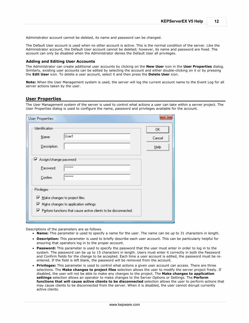
User Properties
The User Management system of the server is used to control what actions a user can take within a server project. TheUser Properties dialog is used to configure the name, password and privileges available for the account.
Descriptions of the parameters are as follows.
Name: This parameter is used to specify a name for the user. The name can be up to 31 characters in length.
Description: This parameter is used to briefly describe each user account. This can be particularly helpful for
ensuring that operators log in to the proper account.
Password: This parameter is used to specify the password that the user must enter in order to log in to the
system. The password can be up to 15 characters in length. Users must enter it correctly in both the Passwordand Confirm fields for the change to be accepted. Each time a user account is edited, the password must be re-entered. If the field is left blank, the password will be removed from the account.
Privileges: This parameter is used to control what actions a given user account can access. There are three
selections. The Make changes to project files selection allows the user to modify the server project freely. Ifdisabled, the user will not be able to make any changes to the project. The Make changes to applicationsettings selection allows an operator to make changes to the Server Options or Settings. The Performfunctions that will cause active clients to be disconnected selection allows the user to perform actions thatmay cause clients to be disconnected from the server. When it is disabled, the user cannot disrupt currentlyactive clients.

13
www.kepware.com
KEPServerEX V5 Help
Settings - Administration
The Administration tab is used to configure the Runtime Administration's actions.
Description of the parameter is as follows:
Automatically start Administration: When checked, this parameter enables the Administration to start
automatically. The Administration is a System Tray application that allows quick links to various server toolsincluding the Settings Console, Configuration, Licensing Utility, User Manager Console and controls for stoppingand starting the Runtime service.
Settings - Configuration
The Configuration tab is used to configure how the Configuration both connects to and interacts with the Runtime.

14
www.kepware.com
KEPServerEX V5 Help
Descriptions of the parameters are as follows.
Communicate using port: This parameter is the TCP/IP port that will be used to communicate between the
Configuration and the Runtime. To obtain the default setting, click Default.
Allow runtime to accept remote connections: When checked, the Runtime will be able to accept remote
connections. The default setting is unchecked.
Maximum number of simultaneous configuration connections: This setting is used to specify the number
of Configuration connections that can be made to the Runtime at one time. The range is 1 to 64. The default is10.
Maximum seconds without communication before session timeout: This setting is used to set the length
of time that the console connection can sit idle before it times out. The range is 10 to 3600 seconds. The defaultis 60 seconds.
Settings - Runtime Process
The Runtime Process tab is used to specify the server Runtime's process mode, as well as how it utilizes the PC'sresources.

15
www.kepware.com
KEPServerEX V5 Help
Descriptions of the parameters are as follows.
Selected Mode: This parameter is used to specify whether the server will be running as System Service or
Interactive. By default, the server installs and runs as System Service. Changing this setting causes all clients,both Configuration and process, to be disconnected and the server to be stopped and restarted.
High Priority: This parameter is used set the server process priority to high. The default setting is normal. When
checked, this setting allows the server to have priority access to resources.
Note: Microsoft recommends against setting applications to a high priority as it can adversely affect otherapplications running on the same PC.
Process Affinity: This parameter is used to specify which CPUs the server can be executed on when it is run on
PCs containing more than one.
Settings - Runtime Options
The Runtime Options tab is used to change settings in the project that's being executed in the Runtime.
16
www.kepware.com
KEPServerEX V5 Help
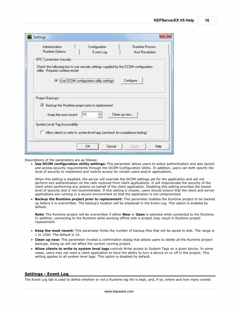
Descriptions of the parameters are as follows:
Use DCOM configuration utility settings: This parameter allows users to select authentication and also launch
and access security requirements through the DCOM Configuration Utility. In addition, users can both specify thelevel of security to implement and restrict access for certain users and/or applications.
When this setting is disabled, the server will override the DCOM settings set for the application and will notperform any authentication on the calls received from client applications. It will impersonate the security of theclient when performing any actions on behalf of the client application. Disabling this setting provides the lowestlevel of security and is not recommended. If this setting is chosen, users should ensure that the client and serverapplications are running in a secure environment so that the application is not compromised.
Backup the Runtime project prior to replacement: This parameter enables the Runtime project to be backed
up before it is overwritten. The backup's location will be displayed in the Event Log. This option is enabled bydefault.
Note: The Runtime project will be overwritten if either New or Open is selected while connected to the Runtime.In addition, connecting to the Runtime while working offline with a project may result in Runtime projectreplacement.
Keep the most recent: This parameter limits the number of backup files that will be saved to disk. The range is
1 to 1000. The default is 10.
Clean up now: This parameter invokes a confirmation dialog that allows users to delete all the Runtime project
backups. Doing so will not affect the current running project.
Allow clients to write to system level tags controls Write access to System Tags on a given device. In some
cases, users may not want a client application to have the ability to turn a device on or off in the project. Thissetting applies to all system level tags. This option is disabled by default.
Settings - Event Log
The Event Log tab is used to define whether or not a Runtime log file is kept; and, if so, where and how many events
17
www.kepware.com
KEPServerEX V5 Help
are logged into it.
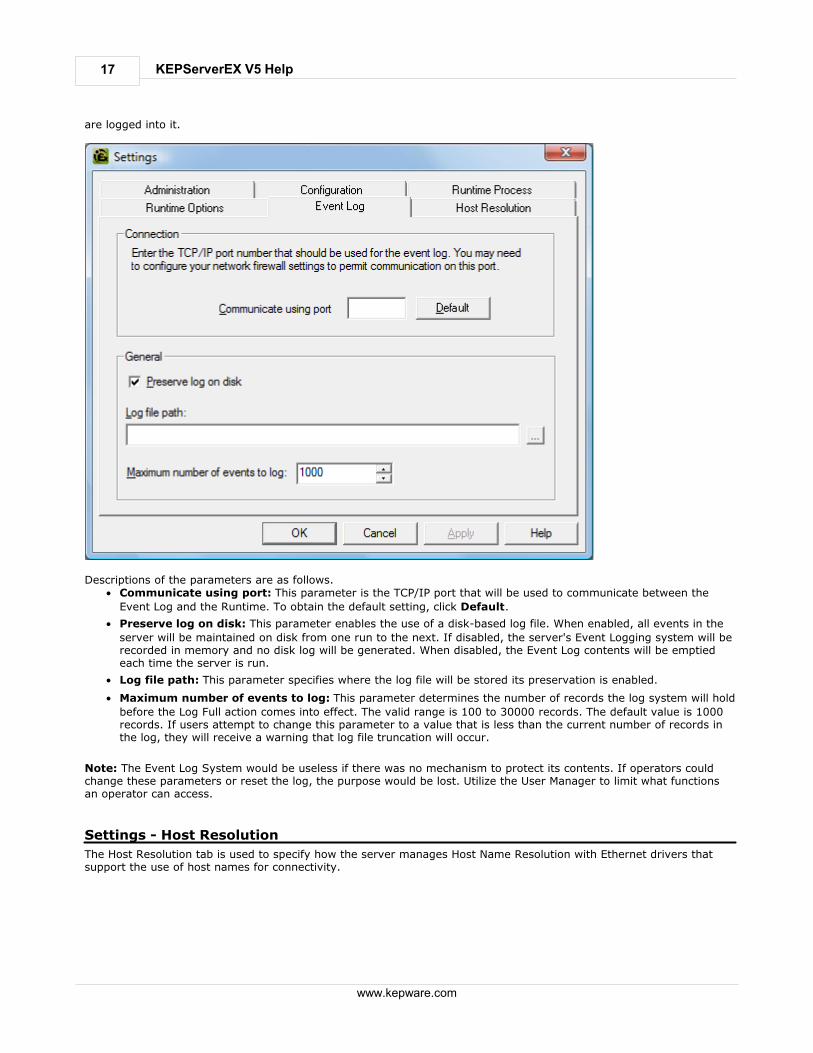
Descriptions of the parameters are as follows.
Communicate using port: This parameter is the TCP/IP port that will be used to communicate between the
Event Log and the Runtime. To obtain the default setting, click Default.
Preserve log on disk: This parameter enables the use of a disk-based log file. When enabled, all events in the
server will be maintained on disk from one run to the next. If disabled, the server's Event Logging system will berecorded in memory and no disk log will be generated. When disabled, the Event Log contents will be emptiedeach time the server is run.
Log file path: This parameter specifies where the log file will be stored its preservation is enabled.
Maximum number of events to log: This parameter determines the number of records the log system will hold
before the Log Full action comes into effect. The valid range is 100 to 30000 records. The default value is 1000records. If users attempt to change this parameter to a value that is less than the current number of records inthe log, they will receive a warning that log file truncation will occur.
Note: The Event Log System would be useless if there was no mechanism to protect its contents. If operators couldchange these parameters or reset the log, the purpose would be lost. Utilize the User Manager to limit what functionsan operator can access.
Settings - Host Resolution
The Host Resolution tab is used to specify how the server manages Host Name Resolution with Ethernet drivers thatsupport the use of host names for connectivity.

18
www.kepware.com
KEPServerEX V5 Help
Descriptions of the parameters are as follows.
Cache resolved names for __ seconds: This parameter is used to determine how long the server will keep the
resolved addresses from host names. The server caches network addresses that it has resolved from host namerequests for a period of time to improve performance when the same address is requested repeatedly. Theperiod is 30 to 7200 seconds. The default is 30 seconds.
Maximum outstanding requests: This parameter is used to specify how many simultaneous requests for Host
Name Resolution can be processed at one time. It allows multiple Ethernet drivers to process at the same timeand also manages the resources that are used to resolve host names. The range is 1 to 8 requests. The default is4.
Tag Management
The server's new user-defined tag management features can be used to create a tag database structure that fits anapplication's specific nature. Multiple tag groups can be defined to segregate the tag data on a device-by-device basis.Drag and drop editing makes adding large numbers of tags easy. Additionally, CSV import and export allows tag editingto be done in any application needed. Like all other server features, new tags can be added to the application at anytime.
Automatic Tag Database Generation
The OPC server supports the automatic generation of tags for select communication drivers. The Automatic TagDatabase Generation feature brings OPC technology one step closer to Plug and Play operation. Drivers that supportthis feature can either Read tag information directly from a device or generate tags from stored tag data. In eithercase, the user no longer needs to manually enter OPC tags into the server.
System Tags
System Tags are used to provide general error feedback to client applications, allow operation control over when adevice is actively collecting data and allow the standard parameters of a either a channel or device to be changed froman OPC client application. The number of System Tags available at either the channel or device-level varies dependingon the nature of the driver being used. The System Tag can also be grouped according to their purpose as both status

19
www.kepware.com
KEPServerEX V5 Help
and control or parameter manipulation.
Property Tags
Tag Properties are available as additional tags that can be accessed by any Data Access client by appending theproperty name to any fully qualified tag address. When using an OPC client that supports item browsing, users canbrowse tag properties by turning on Include tag properties when a client browses the server under OPC DASettings. See Also: Project Properties - OPC DA Settings .
Statistics Tags
Statistics Tags are used to provide feedback to client applications regarding the operation of the channelcommunications in the server. When diagnostics are enabled, there are seven built-in statistics tags available. SeeAlso: OPC Diagnostics Window.
Automatic OPC Tag Database Generation
This server's Automatic OPC Tag Database Generation features have been designed to make setting up the OPCapplication a plug and play operation. Communications drivers that support this feature can be configured toautomatically build a list of OPC tags within the server that correspond to device-specific data. The automaticallygenerated OPC tags can then be browsed from the OPC client. The OPC tags that are generated depend on the natureof the supporting driver. If the target device supports its own local tag database, the driver will read the device's tag information and then usethe data to generate OPC tags within the server. If the device does not natively support its own named tags, the driverwill create a list of tags based on driver-specific information. An example of these two conditions is as follows:
1. If a data acquisition system supports its own local tag database, the communications driver will use the tagnames found in the device to build the server's OPC tags.
2. If an Ethernet I/O system supports detection of its own available I/O module types, the communications driverwill automatically generate OPC tags in the server that are based on the types of I/O modules plugged into theEthernet I/O rack.
Automatic tag database generation's mode of operation is completely configurable. Parameters set in the followingdialog allows users to configure how the server and its associated communications driver will handle automatic OPC tagdatabase generation. Important: When running in System Service Mode, the file from which tags are being created must be located in afolder accessible to System Service in order for it to be loaded by the Runtime. For example, a file residing in a networkdrive that requires authentication will cause the loading to fail. For more information on System Service Mode, refer to Process Mode.

20
www.kepware.com
KEPServerEX V5 Help
The Automatic tag database generation on device startup setting is used to configure when OPC tags will beautomatically generated. Descriptions of the selections are as follows.
Do not generate on startup, the default condition, prevents the driver from adding any OPC tags to the tag
space of the server.
Always generate on startup causes the driver to evaluate the device for tag information and to add OPC tags
to the tag space of the server every time the server is launched.
Generate on first startup causes the driver to evaluate the target device for tag information the first time the
project is run and add any OPC tags to the server tag space as needed.
Note: The Auto-Create button will be disabled when the Configuration edits a project offline. When the option to automatically generate OPC tags is selected, any tags that are added to the server's tag space mustbe saved with the project. Users can configure the project to auto save from the Tools | Options menu.
Perform the Following Action
When automatic OPC tag database generation is enabled, the server needs to know what to do with OPC tags that itmay have added from a previous run or with OPC tags that have been added or modified after the communicationsdriver added them originally. The Perform the following action setting is used to control how the server handles OPCtags that were automatically generated and currently exist in the project. This feature also prevents automaticallygenerated tags from accumulating in the server. For example, review the Ethernet I/O example mentioned above. If users continued to change the I/O modules in therack with the server configured to Always generate new OPC tags on startup, new tags would be added to theserver every time the communications driver detected a new I/O module. If the old tags were not removed, manyunused tags could accumulate in the server's tag space. The Perform the following action setting allows users totailor the server's operation to best fit the application's needs. Descriptions of the selections are as follows.
1. Delete on create, the default condition, deletes any tags that had previously been added to the tag spacebefore the communications driver adds any new tags.
2. Overwrite as necessary instructs the server to remove only those tags that the communications driver isreplacing with new tags. Any tags that are not being overwritten will remain in the server's tag space.
3. Do not overwrite prevents the server from removing any tags that had been previously generated or may havealready existed in the server. With this selection, the communications driver can only add tags that arecompletely new.
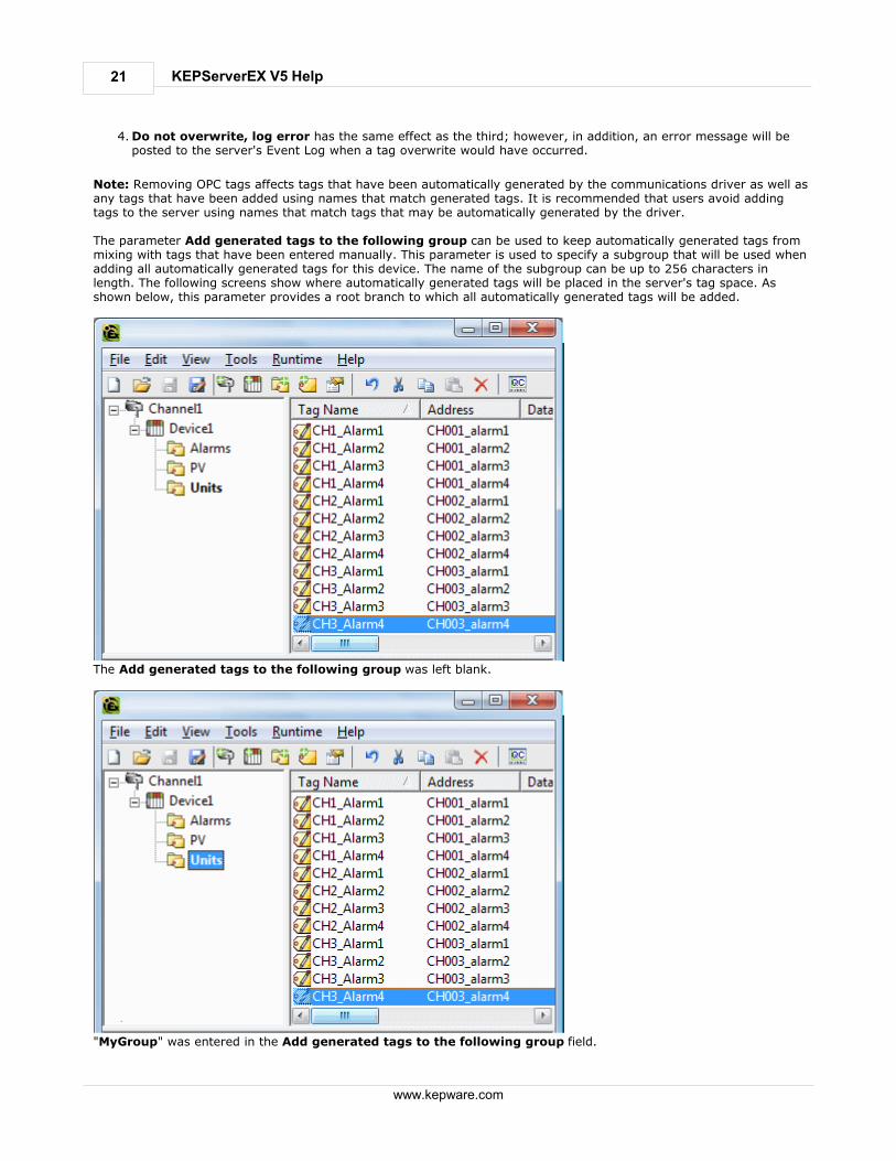
21
www.kepware.com
KEPServerEX V5 Help
4. Do not overwrite, log error has the same effect as the third; however, in addition, an error message will beposted to the server's Event Log when a tag overwrite would have occurred.
Note: Removing OPC tags affects tags that have been automatically generated by the communications driver as well asany tags that have been added using names that match generated tags. It is recommended that users avoid addingtags to the server using names that match tags that may be automatically generated by the driver. The parameter Add generated tags to the following group can be used to keep automatically generated tags frommixing with tags that have been entered manually. This parameter is used to specify a subgroup that will be used whenadding all automatically generated tags for this device. The name of the subgroup can be up to 256 characters inlength. The following screens show where automatically generated tags will be placed in the server's tag space. Asshown below, this parameter provides a root branch to which all automatically generated tags will be added.
The Add generated tags to the following group was left blank.
"MyGroup" was entered in the Add generated tags to the following group field.

22
www.kepware.com
KEPServerEX V5 Help
Allow Automatically Generated Subgroups
The Allow automatically generated subgroups setting controls whether or not the server automatically createssubgroups for the automatically generated tags.
Checked (default)
The server will automatically generate the device's tags and organize them into subgroups. Inthe server project, the resulting tags will retain their tag names.
Unchecked
The server will automatically generate the device's tags in a simple list without anysubgrouping. In the server project, the resulting tags will be named with the address value.For example, the tag names will not be retained during the generation process. The imagebelow shows how the tag names were created using the tag's address.
Note: If, as the server is generating tags, a tag is assigned the same name as an existing tag,the system will automatically increment to the next highest number so that the tag name is notduplicated. For example, if the generation process were to create a tag named AI22 but therealready existed a tag with that name, it would create the tag as AI23 instead.
Auto Create
Auto Create is used to manually initiate the creation of automatically generated OPC tags. If the device's configurationhas been modified, clicking Auto Create will force the communications driver to reevaluate the device for possible tagchanges. Auto Create can be accessed from the System Tags for this device, which allows OPC client application toinitiate tag database creation. Note: With the server's online full-time operation, these parameters can be changed at any time. Utilize the UserManager to restrict access rights to server features in order to prevent operators from changing the parameters.
System Tags
System Tags are used to provide general error feedback to client applications, to allow operational control when adevice is actively collecting data and to allow the standard parameters of a either a channel or device to be changed byan OPC client application when needed.
System Tags
The number of system tags available at both the channel-level or device-level varies depending on the nature of thedriver being used. In addition, application-level system tags allow client applications to monitor the server's status.System tags can also be grouped according to their purpose as both status and control or parameter manipulation.
Parameter Control Tags
While the standard system tags provide needed feedback on server operation, the parameter control tags provide themost powerful feature. Parameter control tags can be used to modify the operational characteristic of the serverapplication. This provides a great deal of flexibility in the OPC applications. By using the parameter control tags, users

23
www.kepware.com
KEPServerEX V5 Help
can implement redundancy by switching communications links or changing the Device ID of a target device. Users canalso provide access to the tags through special supervisory screens that allow a plant engineer to make changes to thecommunication parameters of the server if needed. The tables below include descriptions of the following: Application-Level System Tags
Channel-Level System Tags / Serial
Channel-Level System Tags / Ethernet
Device-level System Tags / Serial and Ethernet
Application-Level System Tags
Syntax Example: <Channel Name>.<Device Name>._System._ActiveTagCount
Tag Description
_ActiveTagCount
Class: Status Tag
The _ActiveTagCount is a tag that indicates the number of tags that arecurrently active in the server.
This is a Read Only tag.
_ClientCount
Class: Status Tag
The _ClientCount is a tag that indicates the number of clients that arecurrently connected to the server.
This is a Read Only tag.
_Date
Class: Status Tag
The _Date is a tag that indicates the current date of the system thatthe server is running on. The format of this string is defined by theoperating system date/time settings.
This is a Read Only tag.
_DateTime
Class: Status Tag
The _DateTime is a tag that indicates the GMT date and time of thesystem that the server is running on. The format of the string is '2004-05-21T20:39:07.000'.
This is a Read Only tag.
_DateTimeLocal
Class: Status Tag
The _DateTimeLocal is a tag that indicates the localized date and timeof the system that the server is running on. The format of the string is'2004-05-21T16:39:07.000'.
This is a Read Only tag.
_FullProjectName
Class: Status Tag
The _FullProjectName is a tag that indicates the fully qualified path andfile name to the currently loaded project.
This is a Read Only tag.
_ProjectName
Class: Status Tag
The _ProjectName is a tag that indicates the currently loaded projectfile name and does not include path information.
This is a Read Only tag.
_Time
Class: Status Tag
The _Time is a tag that indicates the current time of the system thatthe server is running on. The format of this string is defined by theoperating system date/time settings.
This is a Read Only tag.
_TotalTagCount
Class: Status Tag
The _TotalTagCount is a tag that indicates the total number of tags thatare currently being accessed. These tags can be active or inactive.
Note: This count does not represent the number of tags configured inthe project.
This is a Read Only tag.
Channel-level System Tags for Serial Port Driver
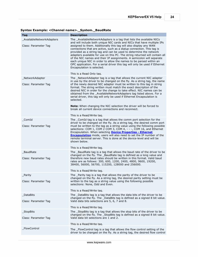
24
www.kepware.com
KEPServerEX V5 Help
Syntax Example: <Channel name>._System._BaudRate
Tag Description
_AvailableNetworkAdapters
Class: Parameter Tag
The _AvailableNetworkAdapters is a tag that lists the available NICsand will include both unique NIC cards and NICs that have multiple IPsassigned to them. Additionally this tag will also display any WANconnections that are active, such as a dialup connection. This tag isprovided as a string tag and can be used to determine the networkadapters available for use on this PC. The string returned will contain allof the NIC names and their IP assignments. A semicolon will separateeach unique NIC in order to allow the names to be parsed within anOPC application. For a serial driver this tag will only be used if EthernetEncapsulation is selected.
This is a Read Only tag.
_NetworkAdapter
Class: Parameter Tag
The _NetworkAdapter tag is a tag that allows the current NIC adapterin use by the driver to be changed on the fly. As a string tag, the nameof the newly desired NIC adapter must be written to this tag in stringformat. The string written must match the exact description of thedesired NIC in order for the change to take effect. NIC names can beobtained from the _AvailableNetworkAdapters tag listed above. For aserial driver, this tag will only be used if Ethernet Encapsulation isselected.
Note: When changing the NIC selection the driver will be forced tobreak all current device connections and reconnect.
This is a Read/Write tag.
_ComId
Class: Parameter Tag
The _ComId tag is a tag that allows the comm port selection for thedriver to be changed on the fly. As a string tag, the desired comm portmust be written to the tag as a string value using the following possibleselections: COM 1, COM 2 COM 3, COM 4, - - -, COM 16, and EthernetEncapsulation. When selecting Device Properties - EthernetEncapsulation mode, users will also need to set the IP number of theremote terminal server. This is done at the device-level and will beshown below.
This is a Read/Write tag.
_BaudRate
Class: Parameter Tag
The _BaudRate tag is a tag that allows the baud rate of the driver to bechanged on the fly. The _BaudRate tag is defined as a long value andtherefore new baud rates should be written in this format. Valid baudrates are as follows: 300, 600, 1200, 2400, 4800, 9600, 19200,38400, 56000, 56700, 115200, 128000 and 256000.
This is a Read/Write tag.
_Parity
Class: Parameter Tag
The _Parity tag is a tag that allows the parity of the driver to bechanged on the fly. As a string tag, the desired parity setting must bewritten to the tag as a string value using the following possibleselections: None, Odd and Even.
This is a Read/Write tag.
_DataBits
Class: Parameter Tag
The _DataBits tag is a tag that allows the data bits of the driver to bechanged on the fly. The _DataBits tag is defined as a signed 8 bit value.Valid data bits selections are 5, 6, 7 and 8.
This is a Read/Write tag.
_StopBits
Class: Parameter Tag
The _StopBits tag is a tag that allows the stop bits of the driver to bechanged on the fly. The _StopBits tag is defined as a signed 8 bit value.Valid data bit selections are 1 and 2.
This is a Read/Write tag.
_FlowControl The _FlowControl tag is a tag that allows the flow control setting of thedriver to be changed on the fly. As a string tag, the desired flow control

25
www.kepware.com
KEPServerEX V5 Help
Class: Parameter Tag setting must be written to the tag in this format. Possible selections forflow control include: None, DTR, RTS, "DTR,RTS", RTS Always and RTSManual. Not all drivers support the RTS Manual mode of operation.
This is a Read/Write tag.
_RtsLineRaise
Class: Parameter Tag
The _RtsLineRaise tag is a tag that allows the RTS Line to be raised fora user-selected period of time before the driver attempts to transmit amessage. This tag will only be effective for drivers that support ManualRTS mode. The _RtsLineRaise is defined as a long value. The validrange is 10 - 2550 milliseconds. The Manual RTS mode has beendesigned for use with radio modems.
This is a Read/Write tag.
_RtsLineDrop
Class: Parameter Tag
The _RtsLineDrop tag is a tag that allows the RTS Line to be loweredfor a user-selected period of time after the driver attempts to transmita message. This tag will only be effective for drivers that supportManual RTS mode. The _RtsLineDrop is defined as a long value. Thevalid range is 0 - 2550 milliseconds. The Manual RTS mode has beendesigned for use with radio modems.
This is a Read/Write tag.
_RtsLinePollDelay
Class: Parameter Tag
The _RtsLinePollDelay tag is a tag that allows a user-configurable pauseto be placed after each message sent from the driver. This tag will onlybe effective for drivers that support Manual RTS mode. The_RtsLinePollDelay is defined as a long value. The valid range is 0 -2550 milliseconds. The Manual RTS mode has been designed for usewith radio modems.
This is a Read/Write tag.
_ReportComErrors
Class: Parameter Tag
The _ReportComErrors tag is a tag that allows the reporting of low levelcommunications errors such as parity and framing errors to be enabledor disabled. This tag is defined as a Boolean tag and can be set eithertrue or false. When true, the driver will report any low-levelcommunications error to the server event system. When set false thedriver will ignore the low-level communications errors and not reportthem. The driver will still reject a communications transaction if itcontains errors. If the environment contains a lot of electrical noise,this feature can be disabled to prevent the Event Log from filling witherror messages.
This is a Read/Write tag.
_EnableDiagnostics
Class: Parameter Tag
The _EnableDiagnostics tag is a tag that allows the diagnostic system ofthe driver to be enabled and disabled. The diagnostic system places alittle additional burden on the driver while enabled. As such the serverallows diagnostics to be enabled or disabled to improve the driver'sperformance. When disabled, the Diagnostics Tags will not beavailable.
This is a Read/Write tag.
_WriteOptimizationDutyCycle
Class: Parameter Tag
The _WriteOptimizationDutyCycle tag is a tag that allows the duty cycleof the Write to Read ratio to be changed on the fly. The duty cyclecontrols how many Writes the driver will do for each Read it performs.The _WriteOptimizationDutyCycle is defined as an unsigned long value.The valid range is 1 to 10 Write per Read.See Also: Channel Properties: Write Optimizations.
This is a Read/Write tag.
Channel-level System Tags for Ethernet Drivers
Syntax Example: <Channel name>._System._NetworkAdapter
Tag Description
_AvailableNetworkAdapters The _AvailableNetworkAdapters is a tag that lists the available NICs
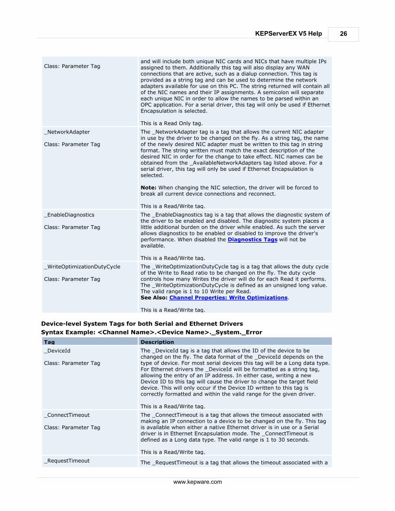
26
www.kepware.com
KEPServerEX V5 Help
Class: Parameter Tagand will include both unique NIC cards and NICs that have multiple IPsassigned to them. Additionally this tag will also display any WANconnections that are active, such as a dialup connection. This tag isprovided as a string tag and can be used to determine the networkadapters available for use on this PC. The string returned will contain allof the NIC names and their IP assignments. A semicolon will separateeach unique NIC in order to allow the names to be parsed within anOPC application. For a serial driver, this tag will only be used if EthernetEncapsulation is selected.
This is a Read Only tag.
_NetworkAdapter
Class: Parameter Tag
The _NetworkAdapter tag is a tag that allows the current NIC adapterin use by the driver to be changed on the fly. As a string tag, the nameof the newly desired NIC adapter must be written to this tag in stringformat. The string written must match the exact description of thedesired NIC in order for the change to take effect. NIC names can beobtained from the _AvailableNetworkAdapters tag listed above. For aserial driver, this tag will only be used if Ethernet Encapsulation isselected.
Note: When changing the NIC selection, the driver will be forced tobreak all current device connections and reconnect.
This is a Read/Write tag.
_EnableDiagnostics
Class: Parameter Tag
The _EnableDiagnostics tag is a tag that allows the diagnostic system ofthe driver to be enabled and disabled. The diagnostic system places alittle additional burden on the driver while enabled. As such the serverallows diagnostics to be enabled or disabled to improve the driver'sperformance. When disabled the Diagnostics Tags will not beavailable.
This is a Read/Write tag.
_WriteOptimizationDutyCycle
Class: Parameter Tag
The _WriteOptimizationDutyCycle tag is a tag that allows the duty cycleof the Write to Read ratio to be changed on the fly. The duty cyclecontrols how many Writes the driver will do for each Read it performs.The _WriteOptimizationDutyCycle is defined as an unsigned long value.The valid range is 1 to 10 Write per Read.See Also: Channel Properties: Write Optimizations.
This is a Read/Write tag.
Device-level System Tags for both Serial and Ethernet Drivers
Syntax Example: <Channel Name>.<Device Name>._System._Error
Tag Description
_DeviceId
Class: Parameter Tag
The _DeviceId tag is a tag that allows the ID of the device to bechanged on the fly. The data format of the _DeviceId depends on thetype of device. For most serial devices this tag will be a Long data type.For Ethernet drivers the _DeviceId will be formatted as a string tag,allowing the entry of an IP address. In either case, writing a newDevice ID to this tag will cause the driver to change the target fielddevice. This will only occur if the Device ID written to this tag iscorrectly formatted and within the valid range for the given driver.
This is a Read/Write tag.
_ConnectTimeout
Class: Parameter Tag
The _ConnectTimeout is a tag that allows the timeout associated withmaking an IP connection to a device to be changed on the fly. This tagis available when either a native Ethernet driver is in use or a Serialdriver is in Ethernet Encapsulation mode. The _ConnectTimeout isdefined as a Long data type. The valid range is 1 to 30 seconds.
This is a Read/Write tag.
_RequestTimeout The _RequestTimeout is a tag that allows the timeout associated with a

27
www.kepware.com
KEPServerEX V5 Help
Class: Parameter Tagdata request to be changed on the fly. The _RequestTimeout tag isdefined as a Long value. The valid range is 100 to 30000 milliseconds.This parameter tag applies to all drivers equally.
This is a Read/Write tag.
_RequestAttempts
Class: Parameter Tag
The _RequestAttempts is a tag that allows the number of retryattempts to be changed on the fly. The _RequestAttempts is defined asa Long value. The valid range is 1 to 10 retries. This parameter tagapplies to all drivers equally.
This is a Read/Write tag.
_InterRequestDelay The _InterRequestDelay is a tag that allows the time interval betweendevice transactions to be changed on the fly. The _InterRequestDelay isdefined as a Long data type. The valid range is 0 to 30000 milliseconds.This parameter tag only applies to drivers that support this feature.
This is a Read/Write tag.
_EncapsulationIp
Class: Parameter Tag
The _EncapsulationIp tag allows the IP of a remote terminal server tobe specified and changed on the fly. This parameter tag is onlyavailable on serial drivers that support Device Properties - EthernetEncapsulation mode. The _EncapsulationIp is defined as a string datatype, allowing the entry of an IP address number. The server will rejectentry of invalid IP addresses. This tag is only valid for a Serial driver inEthernet Encapsulation mode.
This is a Read/Write tag.
_EncapsulationPort
Class: Parameter Tag
The _EncapsulationPort Tag allows the port number of the remoteterminal server to be specified and changed on the fly. The_EncapsulationPort is defined as a long data type. The valid range is 0to 65535. The port number entered in this tag must match that of thedesired remote terminal server for proper Ethernet Encapsulation tooccur. This tag is only valid for a Serial driver in Ethernet Encapsulationmode.
This is a Read/Write tag.
_EncapsulationProtocol
Class: Parameter Tag
The _EncapsulationProtocol tag allows the IP protocol used for EthernetEncapsulation to be specified and changed on the fly. The_EncapsulationProtocol is defined as a string data type. Writing either"TCP/IP" or "UDP" to the tag specifies the IP protocol. The protocolused must match that of the remote terminal server for properEthernet Encapsulation to occur. This tag is only valid for a Serial driverin Ethernet Encapsulation mode.
This is a Read/Write tag.
_AutoCreateTagDatabase
Class: Parameter Tag
The _AutoCreateTagDatabase tag is a Boolean tag that is used toinitiate the automatic OPC tag database functions of this driver for thedevice to which this tag is attached. When this tag is set TRUE, thecommunications driver will attempt to automatically generate an OPCtag database for this device. This tag will not appear for drivers that donot support Automatic OPC Tag Database Generation.
This is a Read/Write tag.
_Enabled
Class: Parameter Tag
The _Enabled tag is a Boolean tag that allows the active state of thedevice to be turned On or Off. When this tag is set FALSE, all otheruser-defined tags and data from this device will be marked as invalidand Writes will not be accepted for the device. When this tag is setTRUE, normal communications will occur with the device.
This is a Read/Write tag.
_Error
Class: Status Tag
The _Error tag is a Boolean tag that returns the current error state ofthe device. When FALSE, the device is operating properly. When setTRUE, the driver has detected an error when communicating with thisdevice. A device enters an error state if it has completed the cycle of
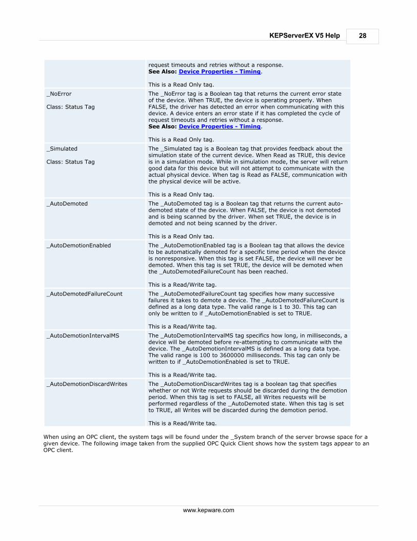
28
www.kepware.com
KEPServerEX V5 Help
request timeouts and retries without a response.See Also: Device Properties - Timing.
This is a Read Only tag.
_NoError
Class: Status Tag
The _NoError tag is a Boolean tag that returns the current error stateof the device. When TRUE, the device is operating properly. WhenFALSE, the driver has detected an error when communicating with thisdevice. A device enters an error state if it has completed the cycle ofrequest timeouts and retries without a response.See Also: Device Properties - Timing.
This is a Read Only tag.
_Simulated
Class: Status Tag
The _Simulated tag is a Boolean tag that provides feedback about thesimulation state of the current device. When Read as TRUE, this deviceis in a simulation mode. While in simulation mode, the server will returngood data for this device but will not attempt to communicate with theactual physical device. When tag is Read as FALSE, communication withthe physical device will be active.
This is a Read Only tag.
_AutoDemoted The _AutoDemoted tag is a Boolean tag that returns the current auto-demoted state of the device. When FALSE, the device is not demotedand is being scanned by the driver. When set TRUE, the device is indemoted and not being scanned by the driver.
This is a Read Only tag.
_AutoDemotionEnabled The _AutoDemotionEnabled tag is a Boolean tag that allows the deviceto be automatically demoted for a specific time period when the deviceis nonresponsive. When this tag is set FALSE, the device will never bedemoted. When this tag is set TRUE, the device will be demoted whenthe _AutoDemotedFailureCount has been reached.
This is a Read/Write tag.
_AutoDemotedFailureCount The _AutoDemotedFailureCount tag specifies how many successivefailures it takes to demote a device. The _AutoDemotedFailureCount isdefined as a long data type. The valid range is 1 to 30. This tag canonly be written to if _AutoDemotionEnabled is set to TRUE.
This is a Read/Write tag.
_AutoDemotionIntervalMS The _AutoDemotionIntervalMS tag specifics how long, in milliseconds, adevice will be demoted before re-attempting to communicate with thedevice. The _AutoDemotionIntervalMS is defined as a long data type.The valid range is 100 to 3600000 milliseconds. This tag can only bewritten to if _AutoDemotionEnabled is set to TRUE.
This is a Read/Write tag.
_AutoDemotionDiscardWrites The _AutoDemotionDiscardWrites tag is a boolean tag that specifieswhether or not Write requests should be discarded during the demotionperiod. When this tag is set to FALSE, all Writes requests will beperformed regardless of the _AutoDemoted state. When this tag is setto TRUE, all Writes will be discarded during the demotion period.
This is a Read/Write tag.
When using an OPC client, the system tags will be found under the _System branch of the server browse space for agiven device. The following image taken from the supplied OPC Quick Client shows how the system tags appear to anOPC client.

29
www.kepware.com
KEPServerEX V5 Help
The _System branch found under the DeviceName branch is always available. If referencing a system tag from a DDEapplication given the above example and the DDE defaults, the link would appear as "<DDE service name>|_ddedata!Channel1.Device1._System._Error". The _Enabled tag provides a very flexible means of controlling the OPC applications. In some cases, specifically inmodem applications, it can be convenient to disable all devices except the device currently connected to the modem.Additionally, using the _Enable tag to allow the application to turn a particular device off while the physical device isbeing serviced can eliminate harmless but unwanted communications errors in the server's Event Log. See Also: Statistics Tags and Property Tags. Note: Modem Tags are described in the topics under Modem Support.
Property Tags
Property Tags are used to provide Read Only access to Tag Properties for client applications. To access a tag property,append the property name to the fully qualified tag address that has been defined in the server's tag database. Formore information, refer to Tag Properties - General. If the fully qualified tag address is "Channel1.Device1.Tag1," its description can be accessed by appending thedescription property as "Channel1.Device1.Tag1._Description".
Supported Property Tag Names
Tag Name Description
_Name The _Name property tag indicates the current name for the tag it isreferencing.
_Address The _Address property tag indicates the current address for the tag it is
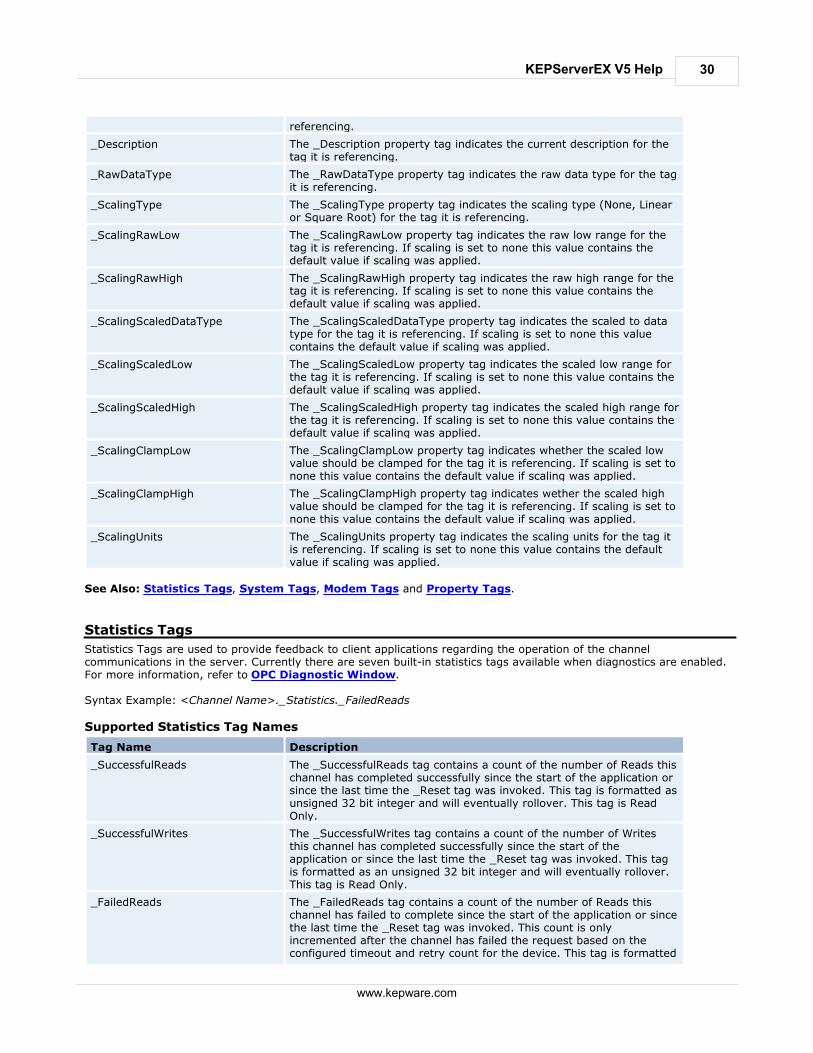
30
www.kepware.com
KEPServerEX V5 Help
referencing.
_Description The _Description property tag indicates the current description for thetag it is referencing.
_RawDataType The _RawDataType property tag indicates the raw data type for the tagit is referencing.
_ScalingType The _ScalingType property tag indicates the scaling type (None, Linearor Square Root) for the tag it is referencing.
_ScalingRawLow The _ScalingRawLow property tag indicates the raw low range for thetag it is referencing. If scaling is set to none this value contains thedefault value if scaling was applied.
_ScalingRawHigh The _ScalingRawHigh property tag indicates the raw high range for thetag it is referencing. If scaling is set to none this value contains thedefault value if scaling was applied.
_ScalingScaledDataType The _ScalingScaledDataType property tag indicates the scaled to datatype for the tag it is referencing. If scaling is set to none this valuecontains the default value if scaling was applied.
_ScalingScaledLow The _ScalingScaledLow property tag indicates the scaled low range forthe tag it is referencing. If scaling is set to none this value contains thedefault value if scaling was applied.
_ScalingScaledHigh The _ScalingScaledHigh property tag indicates the scaled high range forthe tag it is referencing. If scaling is set to none this value contains thedefault value if scaling was applied.
_ScalingClampLow The _ScalingClampLow property tag indicates whether the scaled lowvalue should be clamped for the tag it is referencing. If scaling is set tonone this value contains the default value if scaling was applied.
_ScalingClampHigh The _ScalingClampHigh property tag indicates wether the scaled highvalue should be clamped for the tag it is referencing. If scaling is set tonone this value contains the default value if scaling was applied.
_ScalingUnits The _ScalingUnits property tag indicates the scaling units for the tag itis referencing. If scaling is set to none this value contains the defaultvalue if scaling was applied.
See Also: Statistics Tags, System Tags, Modem Tags and Property Tags.
Statistics Tags
Statistics Tags are used to provide feedback to client applications regarding the operation of the channelcommunications in the server. Currently there are seven built-in statistics tags available when diagnostics are enabled.For more information, refer to OPC Diagnostic Window. Syntax Example: <Channel Name>._Statistics._FailedReads
Supported Statistics Tag Names
Tag Name Description
_SuccessfulReads The _SuccessfulReads tag contains a count of the number of Reads thischannel has completed successfully since the start of the application orsince the last time the _Reset tag was invoked. This tag is formatted asunsigned 32 bit integer and will eventually rollover. This tag is ReadOnly.
_SuccessfulWrites The _SuccessfulWrites tag contains a count of the number of Writesthis channel has completed successfully since the start of theapplication or since the last time the _Reset tag was invoked. This tagis formatted as an unsigned 32 bit integer and will eventually rollover.This tag is Read Only.
_FailedReads The _FailedReads tag contains a count of the number of Reads thischannel has failed to complete since the start of the application or sincethe last time the _Reset tag was invoked. This count is onlyincremented after the channel has failed the request based on theconfigured timeout and retry count for the device. This tag is formatted

31
www.kepware.com
KEPServerEX V5 Help
as an unsigned 32 bit integer and will eventually rollover. This tag isRead Only.
_FailedWrites The _FailedWrites tag contains a count of the number of Writes thischannel has failed to complete since the start of the application or sincethe last time the _Reset tag was invoked. This count is onlyincremented after the channel has failed the request based on theconfigured timeout and retry count for the device. This tag is formattedas unsigned 32 bit integer and will eventually rollover. This tag is ReadOnly.
_RxBytes The _RxBytes tag contains a count of the number of bytes the channelhas received from connected devices since the start of the applicationor since the last time the _Reset tag was invoked. This tag is formattedas unsigned 32 bit integer and will eventually rollover. This tag is ReadOnly.
_TxBytes The _TxBytes tag contains a count of the number of bytes the channelhas sent to connected devices since the start of the application or sincethe last time the _Reset tag was invoked. This tag is formatted asunsigned 32 bit integer and will eventually rollover. This tag is ReadOnly.
_Reset The _Reset tag can be used to reset all diagnostic counters. The _Resettag is formatted as a Boolean tag. Writing a non-zero value to the_Reset tag will cause the diagnostic counters to be reset. This tag isRead/Write.
_MaxPendingReads
The _MaxPendingReads tag contains a count of the maximum numberof pending read requests for the channel since the start of theapplication (or the _Reset tag) was invoked. This tag is formatted as anunsigned 32 bit integer. The tag is Read Only.
_MaxPendingWrites
The _MaxPendingWrites tag contains a count of the maximum numberof pending write requests for the channel since the start of theapplication (or the _Reset tag) was invoked. This tag is formatted as anunsigned 32 bit integer. The tag is Read Only.
_PendingReadsThe _PendingReads tag contains a count of the current pending readrequests for the channel. This tag is formatted as an unsigned 32 bitinteger. The tag is Read Only.
_PendingWritesThe _PendingWrites tag contains a count of the current pending writerequests for the channel. This tag is formatted as an unsigned 32 bitinteger. This tag is Read Only.
Statistics Tags are only available when diagnostics are enabled. To access from an OPC client, the diagnostic tags canbe browsed from the _Statistics branch of the server browse space for a given channel. The following diagram, takenfrom the supplied OPC Quick Client, shows how the Diagnostics Tag appear to an OPC client.

32
www.kepware.com
KEPServerEX V5 Help
The _Statistics branch found under the Channel branch will only appear when diagnostics are enabled for the channel. In order to reference a Diagnostics Tag from a DDE application given the above example and the DDE defaults, the linkwould appear as"<DDE service name>|_ddedata!Channel1._Statistics._SuccessfulReads". The values of the Diagnostics Tag can also be viewed directly in the server by using the Channel Diagnostics window.If "Enable Diagnostics" has been selected under Channel Properties, right-click on that channel and then select Diagnostics. See Also: System Tags and Property Tags. Note: Modem Tags are described in the topics under Modem Support.
Modem Tags
The following tags are created automatically for the channel when modem use is selected. An example of the syntax isas follows: <Channel Name>.<Device Name>._Modem._Dial
Supported Modem Tag Names
Tag Name Description Access
_Dial
Writing any value to this tag initiatesdialing of the current PhoneNumber.The Write is ignored unless thecurrent Status is 3 (Idle). An error isreported if the is current phonenumber has not been initialized.
Read/Write

33
www.kepware.com
KEPServerEX V5 Help
Attempting to issue a dial commandwhile the Mode Tag is set to 2(incoming call only) will generate anerror.
_DialNumber
The DialNumber Tag shows thephone number that is actually dialed,after any dialing preferencetranslations have been applied (suchas the addition of an area code). Thistag is intended for debuggingpurposes. It can provide usefulfeedback to an operator if phonenumbers are entered manually.
Read Only
_Hangup
Writing any value to this tag hangsup the current connection. TheHangup Tag will also hang-up thecurrent connection when an externaldevice has called the server. Writesto the Hangup Tag will be ignored ifthe Status <= 3 (Idle) meaning thatthere is no currently openconnection.
Read/Write
_LastEvent
Whenever the Status changes, thereason for the change is set in thistag as a number. For a list of eventnumbers and meanings, refer to LastEvent Values.
Read Only
_Mode
This allows for configuring the linefor calling only, answering only orboth.
Writing a 1 to the Mode Tag sets theline for outgoing calls only, noincoming calls will be answered whenin this mode. Writing a 2 to the ModeTag sets the line for incoming callsonly, requests to dial out (Writes tothe Dial tag) are ignored. The defaultsetting is 0, which allows for bothoutgoing and incoming calls.
This value can only be changed whenthe Status is <= 3 (Idle).
Read/Write
_PhoneNumber
This is the current phone numberthat will be dialed. Users can Write tothis value at any time, but thechange is only effective if Status is<= 3 (Idle). If users Write to thephone number while the status isgreater than 3, the number will bequeued. As soon as the status dropsto 3 or less, the new number will betransferred to the tag. The queue isof size 1, so only the last phonenumber written will be remembered.
The phone number must be incanonical format in order to applythe dialing preferences. If thecanonical format is used, theresulting number that will be dialed(after dialing preferences have beenapplied) can be displayed as theDialNumber.
Read/Write
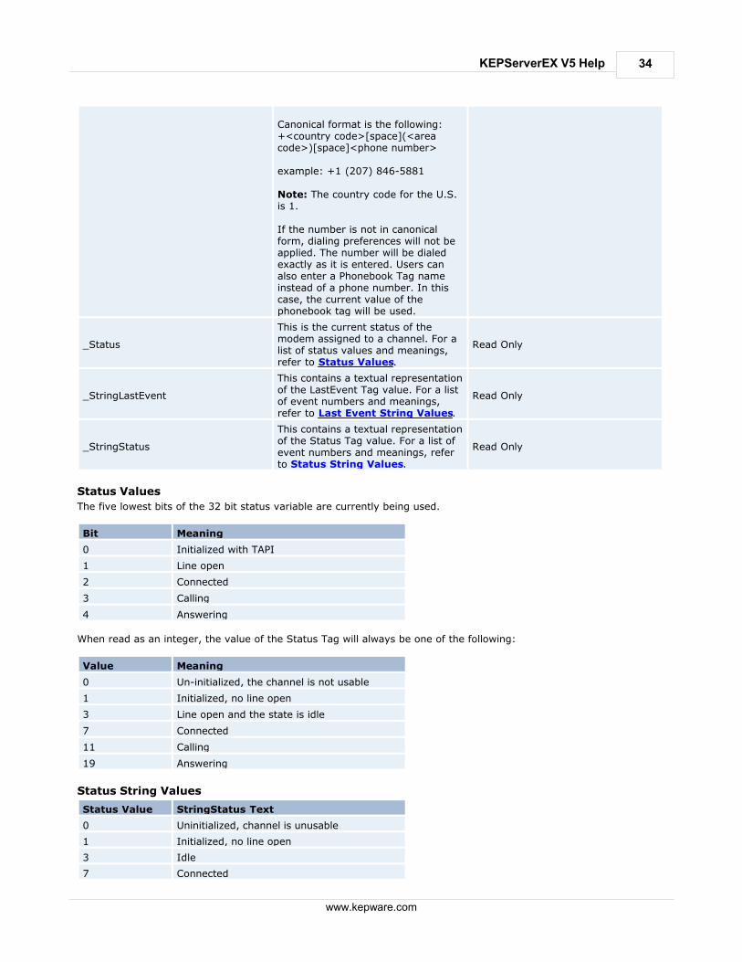
34
www.kepware.com
KEPServerEX V5 Help
Canonical format is the following:+<country code>[space](<areacode>)[space]<phone number>
example: +1 (207) 846-5881
Note: The country code for the U.S.is 1.
If the number is not in canonicalform, dialing preferences will not beapplied. The number will be dialedexactly as it is entered. Users canalso enter a Phonebook Tag nameinstead of a phone number. In thiscase, the current value of thephonebook tag will be used.
_Status
This is the current status of themodem assigned to a channel. For alist of status values and meanings,refer to Status Values.
Read Only
_StringLastEvent
This contains a textual representationof the LastEvent Tag value. For a listof event numbers and meanings,refer to Last Event String Values.
Read Only
_StringStatus
This contains a textual representationof the Status Tag value. For a list ofevent numbers and meanings, referto Status String Values.
Read Only
Status Values
The five lowest bits of the 32 bit status variable are currently being used.
Bit Meaning
0 Initialized with TAPI
1 Line open
2 Connected
3 Calling
4 Answering
When read as an integer, the value of the Status Tag will always be one of the following:
Value Meaning
0 Un-initialized, the channel is not usable
1 Initialized, no line open
3 Line open and the state is idle
7 Connected
11 Calling
19 Answering
Status String Values
Status Value StringStatus Text
0 Uninitialized, channel is unusable
1 Initialized, no line open
3 Idle
7 Connected
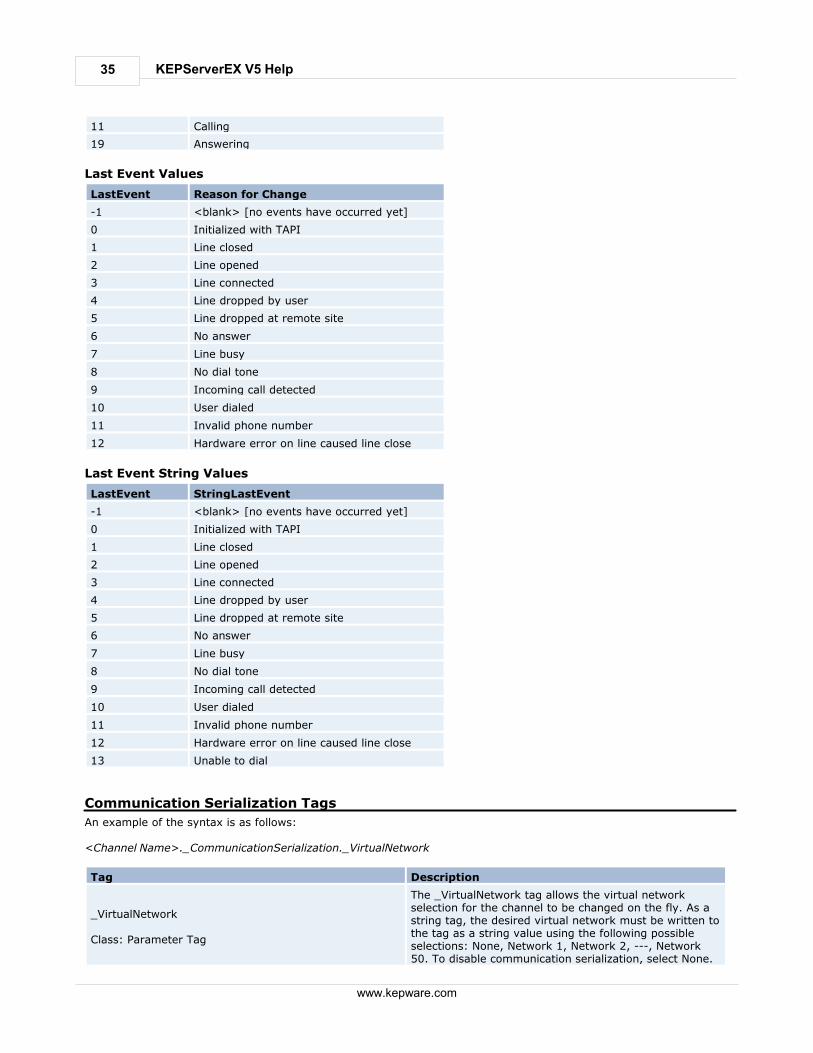
35
www.kepware.com
KEPServerEX V5 Help
11 Calling
19 Answering
Last Event Values
LastEvent Reason for Change
-1 <blank> [no events have occurred yet]
0 Initialized with TAPI
1 Line closed
2 Line opened
3 Line connected
4 Line dropped by user
5 Line dropped at remote site
6 No answer
7 Line busy
8 No dial tone
9 Incoming call detected
10 User dialed
11 Invalid phone number
12 Hardware error on line caused line close
Last Event String Values
LastEvent StringLastEvent
-1 <blank> [no events have occurred yet]
0 Initialized with TAPI
1 Line closed
2 Line opened
3 Line connected
4 Line dropped by user
5 Line dropped at remote site
6 No answer
7 Line busy
8 No dial tone
9 Incoming call detected
10 User dialed
11 Invalid phone number
12 Hardware error on line caused line close
13 Unable to dial
Communication Serialization Tags
An example of the syntax is as follows: <Channel Name>._CommunicationSerialization._VirtualNetwork
Tag Description
_VirtualNetwork
Class: Parameter Tag
The _VirtualNetwork tag allows the virtual networkselection for the channel to be changed on the fly. As astring tag, the desired virtual network must be written tothe tag as a string value using the following possibleselections: None, Network 1, Network 2, ---, Network50. To disable communication serialization, select None.

36
www.kepware.com
KEPServerEX V5 Help
This tag is Read/Write.
_Registered
Class: Status Tag
The _Registered tag indicates whether the channel iscurrently registered to a virtual network. After settingthe _VirtualNetwork, the channel will unregister from thenetwork it is currently registered to (indicated in_RegisteredTo) when it is capable of doing so. In otherwords, if the channel owns control during the switch, itcannot unregister until it has released control. Uponunregistering, the channel will register with new virtualnetwork. This tag will be FALSE if _VirtualNetwork isNone.
This tag is Read Only.
_RegisteredTo
Class: Status Tag
The _RegisteredTo tag indicates the virtual network towhich the channel is currently registered. After settingthe _VirtualNetwork, the channel will unregister from thenetwork it is currently registered to when it is capable ofdoing so. In other words, if the channel owns controlduring the switch, it cannot unregister until it hasreleased control. Upon unregistering, the channel willregister with new virtual network. This tag will indicate ifthere are delays switching networks as _VirtualNetworkand _RegisteredTo could differ for a period of time. Thistag will be N/A if _VirtualNetwork is None.
This tag is Read Only.
_NetworkOwner
Class: Status Tag
The _NetworkOwner tag indicates if the channelcurrently owns control of communications on thenetwork. The frequency of change reflects how often thechannel is granted control.
This tag is Read Only.
_StatisticNetworkOwnershipCount
Class: Status Tag
The _StatisticNetworkOwnershipCount tag indicates thenumber of times the channel has been granted control ofcommunications since the start of the application (orsince the last time _StatisticsReset was written to). Thistag is formatted as an unsigned 32-bit integer and mayeventually rollover.
This tag is Read Only.
_StatisticNetworkOwnershipTimeSec
Class: Status Tag
The _StatisticNetworkOwnershipTimeSec tag indicateshow long in seconds the channel has held ownershipsince the start of the application (or since the last time_StatisticsReset was written to). This tag is formatted asa 32-bit floating point and may eventually rollover.
This tag is Read Only.
_StatisticAvgNetworkOwnershipTimeSec
Class: Status Tag
The _StatisticAvgNetworkOwnershipTimeSec tagindicates how long on average the channel holdsownership of control since the start of the application (orsince the last time _StatisticsReset was written to). Thistag will aid in identifying busy channels/bottlenecks. Thistag is formatted as a 32-bit floating point and mayeventually rollover.
This tag is Read Only.
_StatisticsReset
The _StatisticsReset tag can be used to reset all thestatistic counters. The _StatisticsReset tag is formattedas a Boolean tag. Writing a non-zero value to the_StatisticsReset tag will cause the statistics counters tobe reset.
37
www.kepware.com
KEPServerEX V5 Help
This tag is Read/Write.
Communications Management
Auto-Demotion
The Auto-Demotion parameters allow a driver to temporarily place a device off-scan in the event that a device is notresponding. By placing a nonresponsive device offline, the driver can continue to optimize its communications withother devices on the same channel by stopping communications with the nonresponsive device for a specific timeperiod. After the specific time period has been reached, the driver will re-attempt to communicate with thenonresponsive device. If the device is responsive, the device will be placed on-scan; otherwise, it will restart its off-scan time period. See Also: Device Properties - Auto-Demotion.
Network Interface Selection
Users can select a NIC card for use with any Ethernet driver or serial driver running in Ethernet Encapsulation mode.The Network Interface feature is used to select a specific NIC card based on either the NIC name or its currentlyassigned IP address. The list of available NICs will include both unique NIC cards and NICs that have multiple IPsassigned to them. The selection will also display any WAN connections that may be active (such as a dialup connection).
Ethernet Encapsulation
The Ethernet Encapsulation mode has been designed to provide communications with serial devices connected toterminal servers on the Ethernet network. A terminal server is essentially a virtual serial port: the terminal serverconverts TCP/IP messages on the Ethernet network to serial data. Once the message has been converted to a serialform, users can connect standard devices that support serial communications to the terminal server. Using a terminalserver device allows users to place RS-232 and RS-485 devices throughout the plant operations while still allowing asingle localized PC to access the remotely mounted devices. Furthermore, the Ethernet Encapsulation mode allows anindividual Network IP address to be assigned to each device as needed. By using multiple terminal servers, users canaccess hundreds of serial devices from a single PC via the Ethernet network. For more information, refer to How DoI.. and Device Properties - Ethernet Encapsulation.
Modem Support
This server supports the use of modems to connect to remote devices, which is established through the use of specialmodem tags that become available at the channel-level when a dial-up network connection has been created. Thesechannel-level modem tags can be used to dial a remote device, monitor the modem status while connected andterminate the call when completed. Note: Not all serial drivers support the use of modems. To determine modem support, refer to the specific driver's helpdocumentation. When accessing the new modem tags, the channel name can be used as either a base group or topic name. If theproject contains more than one channel definition, users will need to configure the channel names so that each isunique. This remains true for device names, as well. Channel names can no longer match the device name when theproject needs to be configured to use a modem. The channel name requirements do not apply to projects that are notusing a modem. In order to be used, modems need to be configured with the operating system through the Control Panel settings. Forspecific setup information, refer to the Windows and modem documentation. Once the modem has been properlyinstalled, it can be enabled by selecting the Use Modem checkbox in the Channel Wizard. Important: Many new commercial modems are designed to dial-up network server connections and negotiate thefastest and clearest signal. When communicating to a serial automation device, the modem needs to connect at aspecific Baud (Bits per Second) and Parity. For this reason, we strongly recommend the use of an external modem,which can be configured to dial using specific Baud Rate and Parity settings. To determine the best modem for a specificapplication, check with Technical Support. For examples on how to use a modem in a project, refer to How Do I....
Using a Modem in the Server Project
Modems convert the serial data from the RS-232 port into signal levels that can be transmitted over the phone line. Todo this, modems break each byte of the serial data down into bits used to generate the signal to be transmitted. Mostmodems can handle converting up to 10 bits of information for every byte of data that they send. To communicate witha device via modem, it must be able to use 10 bits or less. The following formula can be used to determine how manybits a specific device is using. Start Bits + Data Bits + Parity + Stop Bits = Total Bit Count

38
www.kepware.com
KEPServerEX V5 Help
For example, if using the Modbus RTU driver we can assume that the device is configured to use 8 Data Bits, EvenParity and 1 Stop Bit (1 Start bit is always implied). When plugged into the formula, it would be 1 + 8 + 1 + 1 = 11Bits. A normal modem would not be able to transmit data to this Modbus device using these settings. If the Parity ischanged to None, however, the result becomes 1 + 8 + 0 + 1=10 Bits. A normal modem can now be used to transmitdata to this Modbus device. Some drivers simply cannot use a normal modem connection and cannot be configured to use a 10 bit or less dataformat. These devices cannot use standard modems. Luckily, there are manufacturers who provide modems that canhandle transmitting 11 data bits. If the driver falls into this category, users should consult the device's manufacturer forrecommendations on an appropriate modem vendor. Modem operation will be enabled for all serial drivers regardless oftheir suitability for modem operation. Note: For the following example instructions, create a project and set the channel settings to use 10 bits or less for theconnection. Configure the device to use the same settings.
Configuring the Initiating Modem
This server uses the Windows TAPI interface to access modems attached to the PC. The TAPI interface was designed toprovide Windows programs a common interface that could be accessed by a range of modems existing in a PC. A set ofdrivers for the Windows OS, which are provided by the modem's manufacturer, must be installed before the server canuse the modem in a project. The Windows Control Panel can be used to install new modems. For information regardingmodem installation and setup, refer to both the Windows and the modem's help documentation. Once the modem has been properly installed, users can begin using it in a server project. The receiving end, or thedevice modem, needs to be properly configured before it can be used. Each driver contains a Modem Configurationpage in its help file. This page contains a listing of the receiving modem's active profile. Users will need to confirm thatthe receiving modem matches the profile provided by the driver.
Configuring the Receiving Modem
Use the Hyperterminal program that is included with Windows to configure the Receiving Modem easily. For moreinformation, follow the instructions below. 1. Use an available Serial Port to connect the desired receiving modem to the PC. Start Hyperterminal and then opena new connection. Name the new connection ModemSetup. 2. In the invoked Connect To dialog, click in the Connect Using drop-down menu and select the communication portto which the receiving modem is attached. Although other modems may appear in this list, they should be ignored forthe moment. 3. In the COMx Properties dialog, configure the communications port settings that will be used to talk to the receivingmodem. Important: The COMx Properties settings must match the Baud Rate, Data Bits, Parity and Stop Bits used by thetarget device. Modems remember the Baud Rate, Data Bits, Parity and Stop Bits that were used to talk to it last; thus,if the receiving modem was configured at 19,200 baud but the device was configured for 9600 baud, the modem willnever be able to speak to the device. Although it could connect, the receiving modem would send all the data to thedevice at 19,200 baud. This is true even if the modem connects at 9600 baud or if the transmitting modem is beingspoken to at 9600 baud. Any disparity between the settings will cause the modem application to fail. To avoid the error,match the settings between the newly created server project and one that has a direct cable connection. 4. Next, enter the port settings. Then, click OK. Note: At this point, users should be able to issue commands to the receiving modem. On many modems, this can betested by typing ATI4 followed by Enter. To ensure this is a valid test for a specific modem, refer to its helpdocumentation. If the modem is properly attached to the PC it will respond by displaying its current profile settings. 5. Set the receiving modem's desired profile and then save the settings by issuing a write command to the modem. Todo so, type AT&W0 followed by Enter. To test the receiving modem's configuration afterwards, simply turn it off for amoment and then turn it back on. Next, type AT14 followed by Enter (or another applicable command). The modemshould display its current profile, including any changes that have been made. Important: The profile settings and reference documents provided here are to be used as examples. Because ofdifferent configuration commands and codes that may be used among modem manufacturers, refer to the specific helpdocumentation to verify all settings.

39
www.kepware.com
KEPServerEX V5 Help
Cables
Before the project is ready to be used, users need to configure the correct cable connection between the receivingmodem and the device. There are 3 cables necessary for this: the existing device communication cable for directconnection, a NULL modem adapter and a NULL modem cable. A NULL modem cable, in which all the pins areconnected to the same pins on both ends of the cable, is connected to the modem. The device communication cable,used to connect to the target device, usually has pins 2 and 3 reversed. Since the cable being used to talk to the devicefor the direct connection is obviously working properly by this point, users can use it on the receiving modem byattaching a NULL modem adapter. Similarly, a PC modem cable will run from the PC to the initiating modem. With thecables in place, users are now ready to use a modem in their application. Note: NULL modem adapters can be found at most computer stores.
Example: Server Side Modem Configuration
After the modems have been properly configured and installed, users can enable their use with the server. At this point,users should refer back to the direct connect project completed earlier when testing the device configuration andcommunications. 1. Load the direct connect project and then double-click on the Channel Name. This will invoke the current directconnect settings for Baud Rate, Parity and etc. 2. Select the Use Modem checkbox. The settings on this page should now become unavailable. 3. Next, click on the Modem tab to display the list of modems available on the computer. Note: If there are no modems visible on list, users will need to exit the server and attempt to reinstall the modemusing the Modem Configuration tools supplied with the operating system. 4. Select the modem that will be used with the server project. At this point, the Dialing... and Properties... buttonsshould become available. Select Properties... Note: The Properties dialog is used to configure the initiating modem's characteristics. There are two sections available:
General is used to set connection speed and speaker volume. The connection speed should be set to match the
speed used by the target device when this was a direct connect project.
Connection is used to configure Data Bits, Parity and Stop Bits. These settings should be set to match the target
device settings.
5. Next, click the Advanced... button. Note: The Advanced Connection dialog is used to configure error correction and flow control for the initiatingmodem. For more information about recommended settings, refer to the specific driver's help documentation. In mostcases, Error Correction and Data Compression can be enabled; Flow Control can be either enabled or disabled,depending. 6. Next, click OK in each dialog until returned to the modem list within the server. When editing an existing project,users can click OK. When editing a new project, users can click Next. If, at this point, an existing direct connect projecthas just been edited, the server project is now ready for modem operation. 7. Save the project.
Using a Modem in Your Application
Once modem operation has been enabled for the driver, a list of predefined tags became available in the driver's TagWindow. These Modem Tags are contained under the Channel Name, which has become an active OPC Access path usedto access the Modem Tags. The Modem Tags are used to control and monitor an attached modem. Operationally, theserver knows very little about what the application needs for modem control; thus, the server does not imply any typeof control over it. By using the predefined Modem Tags, users can apply the application's control or scripting capabilitiesto control the server's use of the selected modem.
Phonebook Tags
A Phonebook Tag can be used in place of specifying a telephone number by directly writing to the PhoneNumber tag. Aphonebook tag can be created on the channel, along with the other modem system tags previously described. The dataassociated with a Phonebook Tag is a phone number that can be assigned when the tag is created and/or later modifiedwhen the server has an active client connection. The phone number stored in a phonebook tag can be used to dial bysimply writing anything to the tag. The act of writing will cause the selected phonebook tag to dial.

40
www.kepware.com
KEPServerEX V5 Help
Syntax Example: <Channel Name>._Phonebook.<Phonebook Tag Name>
Data Type Privilege
String Read/Write
Phonebook Tags are entered using the dialog shown below.
To add a new phonebook tag, simply click on the New Phonebook icon to display the Phone Number dialog.
Example
A phonebook tag name was created for 'Site1.' Syntax Example: <Channel Name>.<Device Name>._Phonebook.Site1
Tag Name Description Access
<Name of Phonebook tag created inModemConfiguration>
Instead of specifying a telephone number by directly writing to the PhoneNumbertag, a phonebook tag can be used. A phonebook tag can be created on thechannel, along with the other modem system tags previously described. The dataassociated with a Phonebook Tag is a phone number that can be assigned whenthe tag is created and/or later modified when the server has an active clientconnection. The phone number stored in a phonebook tag can be used to dial bysimply writing anything to the tag. The act of writing will cause the selectedphonebook tag to dial.
Read/Write
Phone Number
The Phone Number dialog is used to enter a new Phonebook Tag, which can then be used to dial a desired phonenumber. Phonebook Tags keep the list in the server, which is useful if the OPC client application cannot store the phonenumber for a device location. To invoke a phonebook tag, the OPC client must write any string value to the desiredphonebook tag. The phone number dialog should appear as shown below.

41
www.kepware.com
KEPServerEX V5 Help
The Name parameter is used to enter the string that will represent the phone number available from the
phonebook tag. Names can be up to 256 characters in length. Although using descriptive names is generally agood idea, some OPC client applications may have a limited display window when browsing the tag space of anOPC server. The phonebook tag name is part of the OPC browse data. Phonebook Tag names must be uniquewithin a given device.
The Number parameter is used to enter the phone number that will be dialed when the tag is invoked from an
OPC client application. A string of up to 64 digits can be entered.
The Description parameter is used to attach a comment to this tag. A string of up to 64 characters can be
entered.
Note: With the server's online full-time operation, these parameters can be changed at any time. Changes made to TagProperties will take effect immediately; however, OPC clients that have already connected to this tag will not beaffected until they release and reacquire this tag. To prevent operators from changing these parameters use the UserManager to restrict access rights to server features.
Built-In Diagnostics
Communications problems may occur upon occasion that require insight to their cause. In these situations, an advanceduser can employ the various Diagnostics views available to help determine what the communications problem may be.Two diagnostic tools available in the server are the OPC Diagnostics Window and Channel Diagnostics. Theseviews provide both server and driver level Diagnostics for advanced users. Note: Diagnostics should only be utilized when debugging or trouble-shooting because it may affect performance.
OPC Diagnostic Window
The OPC Diagnostics Window provides a real-time and historical view of OPC events that occur between any OPC clientand the server. An event is a method call that a client makes into the server, or a callback the server makes into aclient. This window is separate from the main server configuration window, which can be used to hide the window evenwhile diagnostics are being captured. In the event that there is an issue between a client and the server, theDiagnostics Window can be opened to display the events that have occurred. The operation of this view can becontrolled through the menu, toolbar or by right-clicking in the Event Window. The events and details captured by this utility are specific to the OPC Data Access 1.0, 2.0 and 3.0 CustomSpecifications. To determine the meaning of the data presented by this window, refer to those specifications. Copies ofthese specifications can be found on the OPC Foundation web site: www.opcfoundation.org.

42
www.kepware.com
KEPServerEX V5 Help
OPC Diagnostic Features
The Find Dialog can be used to search for specific text within the diagnostics view. This aids in the debugging of aparticular issue by allowing users to search for key information transferred between the client and server. For example,all actions on a particular Item ID or group name can easily be found using the search functionality.
Users can specify whether the search criteria should be case-sensitive by selecting the Match Case checkbox, orwhether or not to include details in the search by selecting the Search Details checkbox. When an event or detail with the specified text is found, the line containing the text is highlighted. Press F3 to performa Find Next operation which will look for the next occurrence of the specified text. When the last occurrence is found amessage box indicating this condition will be posted. To change the search criteria at any time, press Ctrl+F to invokethe Find Dialog.
The Filter Dialog can be used to select which events will be captured. This aids in debugging a particular issue byeliminating events that do not pertain to a particular issue. For example, most clients will make continuous GetStatuscalls into the server to determine that the server is still available. Filtering this event will simplify the diagnostics data toexamine.

43
www.kepware.com
KEPServerEX V5 Help
Each method (such as, GetErrorString) of every OPC Data Access 1.0, 2.0 and 3.0 interface (such as, IOPCCommon)supported by the server is available as a filter. Users can select a method by clicking the checkbox to the left of themethod name. Additionally, users can select all methods of an interface by double-clicking the interface name. Bydefault, all methods for all interfaces are selected. Note: Filter changes apply only to new events captured. Previous events that meet the filter criteria will not beremoved from the view.
The Options Dialog is used to control certain functionality built into the OPC diagnostics feature.
Remember that the performance of the server is affected by capturing diagnostic information, as it is an additional layerof processing that occurs between all client/server communications. The OPC diagnostic information is saved to theinstallation directory under the file name autosave.opcdiag. The file is only created on shutdown. This functionality isturned off by default. Users can also decide whether of not to persist OPC diagnostic information to disk when the server is shutdown byselecting the Preserve diagnostics to disk on shutdown. This can be useful if users need to go back in time todetermine where a particular issue may have occurred. Users can also create a backup of diagnostics data at any timethrough the File | Save As menu option. By default, this functionality is turned on.

44
www.kepware.com
KEPServerEX V5 Help
Since diagnostic information affects memory/file storage, users can decide the maximum number of OPC diagnosticevents that should be captured at any specific time by modifying the Maximum number of diagnostics to capture.This value only pertains to the number of events and does not include the number of details, as the detail count for aparticular event could be potentially very high. The range for this setting is 1000 to 30000. The default value is 5000.
OPC Diagnostic Events
Click on a link below to jump to any of the following OPC Diagnostic Events. IClassFactory
Server
IOPCCommon
IOPCServer
IConnectionPointContainer(Server)
IOPCBrowse
IOPCBrowseServerAddressSpace
IOPCItemProperties
IOPCItemIO
IOPCGroupStateMgt
IOPCGroupStateMgt2
IOPCItemDeadbandMgt
IOPCItemSamplingMgt
IOPCSyncIO
IOPCSyncIO2
IOPCAsyncIO
IDataObject
IAdviseSink
IOPCAsyncIO2
IAsyncIO3
IConnectionPointContainer (Group)
IOPCDataCallback
IEnumOPCItemAttributes
IClassFactory
The IClassFactory interface contains several methods intended to deal with an entire class of objects. It is implementedon the class object for a specific class of objects and is identified by a CLSID.
QueryInterface - The client can ask the object whether it supports any outgoing interfaces by calling
QueryInterface for IConnectionPointContainer. If the object answers "yes" by handing back a valid pointer, theclient knows it can attempt to establish a connection.
AddRef - Increments the reference count for an interface on an object. It should be called for every new copy of
a pointer to an interface on a given object.
Release - Decreases the reference count of the interface by 1.
CreateInstance - Creates an uninitialized object.
LockServer - Allows instances to be created quickly when called by the client of a class object to keep a server
open in memory.
Server
The client calls CoCreateInstance to create the Server object and the initial interface. QueryInterface - The client can ask the object whether it supports any outgoing interfaces by calling
QueryInterface for IConnectionPointContainer. If the object answers "yes" by handing back a valid pointer, theclient knows it can attempt to establish a connection.
AddRef - Increments the reference count for an interface on an object. It should be called for every new copy of
a pointer to an interface on a given object.
Release - Decreases the reference count of the interface by 1.
IOPCCommon
This interface is used by all OPC Server types (DataAccess, Alarm&Event, Historical Data and etc.). It provides the

45
www.kepware.com
KEPServerEX V5 Help
ability to set and query a Locale ID which would be in effect for the particular client/server session. That is, the actionsof one client do not affect other clients.
GetErrorString - Returns the error string for a server specific error code. The expected behavior is that this will
include handling of Win32 errors as well (such as RPC errors).
GetLocale ID - Returns the default Locale ID for this server/client session.
QueryAvailableLocale IDs - Returns the available Locale IDs for this server/client session.
SetClientName - Allows the client to optionally register a client name with the server. This is included primarily
for debugging purposes. The recommended behavior is that users set the Node name and EXE name here.
Set LocalID - Sets the default Locale ID for this server/client session. This Locale ID will be used by the
GetErrorString method on this interface. The default value for the server should be LOCALE_SYSTEM_DEFAULT.
IOPCServer
This is the main interface to an OPC server. The OPC server is registered with the operating system as specified in theInstallation and Registration Chapter of this specification.
AddGroup - Adds a Group to a Server. A Group is a logical container for a client to organize and manipulate data
items.
CreateGroupEnumerator - Creates various enumerators for the groups provided by the Server.
GetErrorString - Returns the error string for a server specific error code.
GetGroupByName - Returns an additional interface pointer when given the name of a private group (created
earlier by the same client). Use GetPublicGroupByName to attach to public groups. This function can be used toreconnect to a private group for which all interface pointers have been released.
GetStatus - Returns current status information for the server.
RemoveGroup - Deletes the Group. A group is not deleted when all the client interfaces are released, since the
server itself maintains a reference to the group. The client may still call GetGroupByName after all the interfaceshave been released. RemoveGroup() causes the server to release it's 'last' reference to the group, which resultsin the group being deleted.
IConnectionPointContainer(Server)
This interface provides the access to the connection point for IOPCShutdown. EnumConnectionPoints - Creates an enumerator for the connection points supported between the OPC Group
and the Client. OPCServers must return an enumerator that includes IOPCShutdown. Additional vendor specificcallbacks are allowed.
FindConnectionPoints - Finds a particular connection point between the OPC Server and the Client. OPCServers
must support IID_IOPCShutdown. Additional vendor specific callbacks are allowed.
IConnectionPoint(Server) - Establishes a call back to the client.
Advise - Establishes an advisory connection between the connection point and the caller's sink object.
EnumConnections - Creates an enumerator object for iteration through the connections that exist to this
connection point.
GetConnectionInterface - Returns the IID of the outgoing interface managed by this connection point.
UnAdvise - Terminates an advisory connection previously established through the Advise method.
IOPCBrowse
IOPCBrowse interface provides improved methods for browsing the server address space and for obtaining the itemproperties.
GetProperties - Returns an array of OPCITEMPROPERTIES, one for each Item ID.
Browse - Browses a single branch of the address space and returns zero or more OPCBROWSEELEMENT
structures.
IOPCBrowseServerAddressSpace
This interface provides a way for clients to browse the available data items in the server, giving the user a list of thevalid definitions for an Item ID. It allows for either flat or hierarchical address spaces and is designed to work well overa network. It also insulates the client from the syntax of a server vendor specific Item ID.
BrowseAccessPaths - Provides a way to browse the available AccessPaths for an Item ID.
BrowseOPCItem IDs - Returns an IENUMString for a list of Item IDs as determined by the passed parameters.
The position from which the browse is made can be set in ChangeBrowsePosition.
ChangeBroserPosition - Provides a way to move up, down or to in a hierarchical space.
GetItem ID - Provides a way to assemble a fully qualified Item ID in a hierarchical space. This is required since
the browsing functions return only the components or tokens that make up an Item ID and do not return thedelimiters used to separate those tokens. Also, at each point one is browsing just the names below the current

46
www.kepware.com
KEPServerEX V5 Help
node (e.g. the units in a cell).
QueryOrganization - Provides a way to determine if the underlying system is inherently flat or hierarchical and
how the server may represent the information of the address space to the client. Flat and hierarchical spacesbehave somewhat different. If the result is flat then the client knows that there is no need to pass the Branch orLeaf flags to BrowseOPCItem IDs or to call ChangeBrowsePosition.
IOPCItemProperties
This interface can be used to browse the available properties associated with an Item ID as well as to Read theproperties' current values.
GetItemProperties - Returns a list of the current data values for the passed ID codes.
LockUpItem IDs - Returns a list of Item IDs for each of the passed ID codes if any are available. These indicate
the Item ID which could be added to an OPCGroup and used for more efficient access to the data correspondingto the Item Properties.
QueryAvailableProperties - Returns a list of ID codes and descriptions for the available properties for this Item
ID. This list may differ for different Item IDs. This list is expected to be relatively stable for a particular Item ID,although it could be affected from time to time by changes to the underlying system's configuration. The Item IDis passed to this function because servers are allowed to return different sets of properties for different Item IDs.
IOPCItemIO
The purpose of this interface is to provide an extremely easy way for simple applications to obtain OPC data. Read - Reads one or more values, qualities and timestamps for the items specified. This is functionally similar to
the IOPCSyncIO::Read method.
WriteVQT - Writes one or more values, qualities and timestamps for the items specified. This is functionally
similar to the IOPCSyncIO2::WriteVQT except that there is no associated group. If a client attempts to write VQ,VT, or VQT it should expect that the server will Write them all or none at all.
Group - The client calls CoCreateInstance to create the Server object and the initial interface.
QueryItnerface - The client can ask the object whether it supports any outgoing interfaces by calling
QueryInterface for IConnectionPointContainer. If the object answers "yes" by handing back a valid pointer, theclient knows it can attempt to establish a connection.
AddRef - Increments the reference count for an interface on an object. It should be called for every new copy of
a pointer to an interface on a given object.
Release - Decreases the reference count of the interface by 1.
IOPCGroupStateMgt
IOPCGroupStateMgt allows the client to manage the overall state of the group. Primarily, this accounts for changesmade to the group's update rate and active state.
CloneGroup - Creates a second copy of a group with a unique name.
GetState - Gets the current state of the group. This function is typically called to obtain the current values of
this information prior to calling SetState. This information was all supplied by or returned to the client when thegroup was created.
SetName - Changes the name of a private group. The name must be unique. The name cannot be changed for
public groups. Group names are required to be unique with respect to an individual client to server connection.
SetState - Sets various properties of the group. This represents a new group which is independent of the
original group.
IOPCGroupStateMgt2
This interface was added to enhance the existing IOPCGroupStateMgt interface. SetKeepAlive - Causes the server to provide client callbacks on the subscription when there are no new events
to report. Clients can then be assured of the health of the server and subscription without resorting to pingingthe server with calls to GetStatus().
GetKeepAlive - Returns the currently active keep-alive time for the subscription.
IOPCItemMgt - IOPCItemMgt allows a client to add, remove and control the behavior of items is a group.
AddItems - Adds one or more items to a group. It is acceptable to add the same item to the group more than
once, thus generating a second item with a unique ServerHandle.
CreateEnumerator - Creates an enumerator for the items in the group.
RemoveItems - Removes items from a group. Removing items from a group does not affect the address space
of the server or physical Device. It simply indicates whether or not the client is interested in those particularitems.
SetactiveState - Sets one or more items in a group to active or inactive. This controls whether or not valid data

47
www.kepware.com
KEPServerEX V5 Help
can be obtained from Read cache for those items and whether or not they are included in the IAdvisesubscription to the group. Deactivating items will not result in a callback, since by definition callbacks do notoccur for inactive items. Activating items will generally result in an IAdvise callback at the next UpdateRateperiod.
SetClientHandles - Changes the client handle for one or more items in a group. In general, it is expected that
clients will set the client handle when the item is added and not change it later.
SetDataTypes - Changes the requested data type for one or more items in a group. In general, it is expected
that clients will set the requested datatype when the item is added and not change it later.
ValidateItems - Determines if an item is valid and could be added without error. It also returns information
about the item such as canonical datatype. It does not affect the group in any way.
IOPCItemDeadbandMgt
Force a callback to IOPCDataCallback::OnDataChange for all active items in the group, whether they have changed ornot. Inactive items are not included in the callback. The MaxAge value will determine where the data is obtained. Therewill be only one MaxAge value, which will determine the MaxAge for all active items in the group. This means some ofthe values may be obtained from cache while others could be obtained from the Device depending on the "freshness" ofthe data in the cache.
SetItemDeadband - Overrides the deadband specified for the group for each item.
GetItemDeadband - Gets the deadband values for each of the requested items.
ClearItemDeadband - Clears the individual item PercentDeadband, effectively reverting them back to the
deadband value set in the group.
IOPCItemSamplingMgt
This optional interface allows the client to manipulate the rate at which individual items within a group are obtainedfrom the underlying Device. It does not affect the group update rate of the callbacks for OnDataChange.
SetItemSamplingRate - Sets the sampling rate on individual items. This overrides the update rate of the group
as far as collection from the underlying Device is concerned. The update rate associated with individual itemsdoes not affect the callback period.
GetItemSamplingRate - Gets the sampling rate on individual items, which was previously set with
SetItemSamplingRate.
ClearItemSamplngRate - Clears the sampling rate on individual items, which was previously set with
SetItemSamplingRate. The item will revert back to the update rate of the group.
SetItemBufferEnable - Requests that the server turns on or off, depending on the value of the bEnable
parameter, the buffering of data for the identified items, which are collected for items that have an update ratefaster than the group update rate.
GetItemBufferEnable - Queries the current state of the servers buffering for requested items.
IOPCSyncIO
IOPCSyncIO allows a client to perform synchronous Read and Write operations to a server. The operations will run tocompletion.
Read - Reads the value, quality and timestamp information for one or more items in a group. The function runs
to completion before returning. The data can be read from cache in which case it should be accurate to within the'UpdateRate' and percent deadband of the group. The data can be read from the Device, in which case an actualRead of the physical Device must be performed. The exact implementation of cache and Device Reads is notdefined by the specification.
Write- Writes values to one or more items in a group. The function runs to completion. The values are written to
the Device, meaning that the function should not return until it verifies that the Device has actually accepted orrejected the data. Writes are not affected by the active state of the group or item.
IOPCSyncIO2
This interface was added to enhance the existing IOPCSyncIO interface. ReadMaxAge - Reads one or more values, qualities and timestamps for the items specified. This is functionally
similar to the OPCSyncIO::Read method except no source is specified (Device or cache). The server will makethe determination as whether the information will be obtained from the Device or cache. This decision will bebased upon the MaxAge parameter. If the information in the cache is within the MaxAge, then the data will beobtained from the cache, otherwise the server must access the Device for the requested information.
WriteVQT - Writes one or more values, qualities and timestamps for the items specified. This is functionally
similar to the IOPCSyncIO::Write except that Quality and Timestamp may be written. If a client attempts to writeVQ, VT or VQT it should expect that the server will Write to all or none.
IOPCAsyncIO
IOPCAsyncIO allows a client to perform asynchronous Read and Write operations to a server. The operations will be

48
www.kepware.com
KEPServerEX V5 Help
'queued' and the function will return immediately so that the client can continue to run. Each operation is treated as a'transaction' and is associated with a Transaction ID. As the operations are completed, a callback will be made to theIAdvise Sink in the client (if one has been established). The information in the callback will indicate the Transaction IDand the error results. By convention, 0 is an invalid Transaction ID.
Cancel - Requests that the server cancel an outstanding transaction.
Read - Reads one or more items in a group. The results are returned via the IAdvise Sink connection established
through the IDataObject. For cache Reads the data is only valid if both the group and the item are active. DeviceReads are not affected by the active state of the group or item.
Refresh - Forces a callback for all active items in the group, whether they have changed or not. Inactive items
are not included in the callback.
Write - Writes one or more items in a group. The results are returned via the IAdviseSink connection established
through the IDataObject.
IDataObject
IDataObject is implemented on the OPCGroup rather than on the individual items. This allows the creation of an Adviseconnection between the client and the group using the OPC Data Stream Formats for the efficient data transfer.
DAdvise - Create a connection for a particular 'stream' format between the OPC Group and the Client.
DUnadvise - Terminate a connection between the OPC Group and the Client.
IAdviseSink
The client only has to provide a full implementation of OnDataChange. OnDataChange - This method is provided by the client to handle notifications from the OPC Group for exception
based data changes, Async Reads and Refreshes and Async Write Complete.
IOPCAsyncIO2
This interface is similar to IOPCAsync(OPC 1.0) and is intended to replace IOPCAsyncIO. It was added in OPC 2.05. Cancel2 - Requests that the server cancel an outstanding transaction.
GetEnable - Retrieves the last Callback Enable value set with SetEnable.
Read - Reads one or more items in a group. The results are returned via the client's IOPCDataCallback
connection established through the server's IConnectionPointContainer. Reads are from 'Device' and are notaffected by the active state of the group or item.
Refresh2 - Forces a callback to IOPCDataCallback::OnDataChange for all active items in the group, whether they
have changed or not. Inactive items are not included in the callback.
SetEnable - Controls the operation of OnDataChange. Setting Enable to False will disable any OnDataChange
callbacks with a transaction ID of 0 (which are not the result of a Refresh). The initial value of this variable whenthe group is created is True; thus, OnDataChange callbacks are enabled by default.
Write - Writes one or more items in a group. The results are returned via the client's IOPCDataCallback
connection established through the server's IConnectionPointContainer.
IAsyncIO3
This interface was added to enhance the existing IOPCAsyncIO2 interface. ReadMaxAge - Reads one or more values, qualities and timestamps for the items specified. This is functionally
similar to the OPCSyncIO::Read method except it is asynchronous and no source is specified (Device or cache).The server will make the determination as whether the information will be obtained from the Device or cache.This decision will be based upon the MaxAge parameter. If the information in the cache is within the MaxAge,then the data will be obtained from the cache; otherwise, the server must access the Device for the requestedinformation.
WriteVQT - Writes one or more values, qualities and timestamps for the items specified. The results are
returned via the client's IOPCDataCallback connection established through the server'sIConnectionPointContainer. This is functionally similar to the IOPCAsyncIO2::Write except that Quality andTimestamp may be written. If a client attempts to write VQ, VT or VQT it should expect that the server will Writethem all or none at all.
RefreshMaxAge - Forces a callback to IOPCDataCallback::OnDataChange for all active items in the group,
whether or not they have changed. Inactive items are not included in the callback. The MaxAge value determineswhere the data is obtained. There will be only one MaxAge value, which determines the MaxAge for all activeitems in the group. This means some of the values may be obtained from cache while others can be obtainedfrom the Device, depending on the type of the data in the cache.
IConnectionPointContainer (Group)
This interface provides functionality similar to the IDataObject but is easier to implement and to understand. It alsoprovides the functionality missing from the IDataObject Interface. The client must use the new IOPCAsyncIO2 interfaceto communicate via connections established with this interface. The 'old' IOPCAsnyc will continue to communicate via

49
www.kepware.com
KEPServerEX V5 Help
IDataObject connections as in the past. EnumConnectionPoints - Creates an enumerator for the Connection Points supported between the OPC Group
and the Client.
FindConnectionPoint - Finds a particular connection point between the OPC Group and the Client.
IconnectionPoint (Group) - Establishes a call back to the client.
Advise - Establishes an advisory connection between the connection point and the caller's sink object.
EnumConnections - Creates an enumerator object for iteration through the connections that exist to this
connection point.
GetConnectionInterface - Returns the IID of the outgoing interface managed by this connection point.
GetConnectionPointContainer - Retrieves the IConnectionPointContainer interface pointer to the connectable
object that conceptually owns the connection point.
Unadvise - Terminates an advisory connection previously established through the Advise method.
IOPCDataCallback
In order to use connection points, the client must create an object that supports both the IUnknown andIOPCDataCallback Interface.
OnDataChange - This method is provided by the client to handle notifications from the OPC Group for exception
based data changes and Refreshes.
OnReadComplete - This method is provided by the client to handle notifications from the OPC Group on
completion of Async Reads.
OnWriteComplete - This method is provided by the client to handle notifications from the OPC Group on
completion of AsyncIO2 Writes.
OnCancelComplete - This method is provided by the client to handle notifications from the OPC Group on
completion of Async Cancel.
IEnumOPCItemAttributes
IEnumOPCItemAttributes allows clients to find out the contents of a group and the attributes of those items. Most of thereturned information is either supplied by or returned to the client at the time it called AddItem.
Clone - Creates a second copy of the enumerator. The new enumerator is initially in the same state as the
current enumerator.
Next - Fetches the next 'celt' items from the group.
Reset - Resets the enumerator back to the first item.
Skip - Skips over the next 'celt' attributes.
Important: For more information on the general principles of Connection points, refer to Microsoft documentation.
Channel Diagnostics
The server's diagnostic features provides real-time data on the communication driver's performance. All Read and Writeoperations can either be viewed in the diagnostic display window or tracked directly in the OPC client application byusing built-in Diagnostics Tags. These diagnostics make it easy to debug communication issues. The diagnosticdisplay window also provides a real-time protocol view, which is useful when making changes to key communicationparameter settings (such as baud rate, parity or Device IDs). The changes' effects are displayed in real-time. Once thecorrect communication and device settings are set, users will immediately see the exchange of data with the device. To modify the operation of the Diagnostic Window, right-click in the window's protocol view.

50
www.kepware.com
KEPServerEX V5 Help
Note: The Diagnostic Window operates in a modeless form that allows it to exist while other dialogs in the server areopen.
Diagnostic Controls
Descriptions of the Diagnostics Controls are as follows. Pause captures and freezes the protocol data in the Diagnostics Window. The Diagnostics Tags will continue to
be updated.
Reset clears only the contents of the protocol view and does not affect the Diagnostics Tags.
Mode displays the protocol information in a pure Hex representation (Hex Mode) or in a mixture of ASCII and
Hex representation (Mix Mode). Depending on the target device's nature, the Mode selection may need to bechanged to provide the best view of the protocol.
Auto Pause on failure function causes the capture buffer of the protocol view to stop whenever either a Read or
Write error occurs. This selection is turned off by default and the protocol capture will run in continuous mode.Auto Pause is a great way to capture intermittent communications issues.
Using the Diagnostic Window
Before attempting to use the Diagnostic Window, ensure that diagnostic functions have been enabled in ChannelProperties. Next, display the Diagnostic Window by either selecting it from a context menu on the channel or byclicking View | Diagnostics. Once the diagnostic menu is displayed, it will begin capturing the real-time protocol data.If communications are occurring properly, there will be a stream of communications messages between the server andthe device. Users can tell when this is occurring due to both the two-color scheme of the protocol window and by thecurrent counts of the Diagnostics Tags. If, for some reason, communications do not appear to be occurring normally, the channel's parameters can be accessedeasily. The diagnostic window will remain displayed even when users display the Channel Properties for settings like thecommunications parameters. This allows users to interactively change communications parameters while monitoring the

51
www.kepware.com
KEPServerEX V5 Help
effect in the protocol view. Remember to display the diagnostic window before accessing any parameter dialogs. Once the diagnostic window is displayed, various communication and device settings in the channel and device can bemodified to see the effect on the communications stream. If a communications problem persists, right-click in thediagnostic window to invoke the context menu. The selections available from this menu can be used to tailor theoperation of the diagnostic window and copy the contents of the protocol view to the Clipboard.
Descriptions are as follows.
Copy to Clipboard helps Technical Support solve many communications issues when they occur. This selection
formats the protocol capture buffer's contents as text for easy "cut and paste" into either an email or faxmessage (which can then be sent to Technical Support for analysis and diagnosis).
Save as Text File saves the current contents of the protocol view directly to a text file.
Auto Scroll ensures that the protocol view will automatically scroll to the next line as new protocol data is
received.
Always on Top forces the Diagnostics Window to remain on the top of all other application windows. This is the
default condition.
Options… is used to select a buffer size for the protocol capture buffer, set the font and size used by the
protocol view and also assign unique colors to both the transmit and receive data streams.
Buffer Size is used to select a capture buffer of 1024, 2048, 4096, 8192, 16384, 32768 or 65536 bytes. Depending onthe device's speed, a larger buffer size may be needed to effectively capture protocol related issues.
Display is used to tailor the appearance of the protocol view. The Background, TX Characters and RX Characters colorselections can be used to select from a palette of 16 available colors. Each selection is required to be unique. The fontused by the protocol view can also be selected from this dialog, as well as the size of that font. When selecting a font,
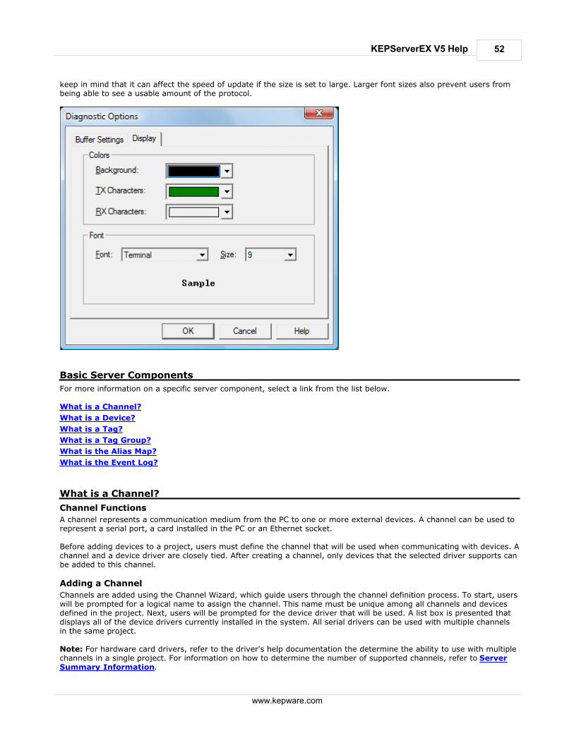
52
www.kepware.com
KEPServerEX V5 Help
keep in mind that it can affect the speed of update if the size is set to large. Larger font sizes also prevent users frombeing able to see a usable amount of the protocol.
Basic Server Components
For more information on a specific server component, select a link from the list below. What is a Channel?
What is a Device?
What is a Tag?
What is a Tag Group?
What is the Alias Map?
What is the Event Log?
What is a Channel?
Channel Functions
A channel represents a communication medium from the PC to one or more external devices. A channel can be used torepresent a serial port, a card installed in the PC or an Ethernet socket. Before adding devices to a project, users must define the channel that will be used when communicating with devices. Achannel and a device driver are closely tied. After creating a channel, only devices that the selected driver supports canbe added to this channel.
Adding a Channel
Channels are added using the Channel Wizard, which guide users through the channel definition process. To start, userswill be prompted for a logical name to assign the channel. This name must be unique among all channels and devicesdefined in the project. Next, users will be prompted for the device driver that will be used. A list box is presented thatdisplays all of the device drivers currently installed in the system. All serial drivers can be used with multiple channelsin the same project. Note: For hardware card drivers, refer to the driver's help documentation the determine the ability to use with multiplechannels in a single project. For information on how to determine the number of supported channels, refer to ServerSummary Information.
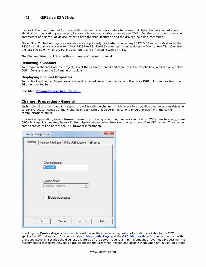
53
www.kepware.com
KEPServerEX V5 Help
Users will then be prompted for the specific communication parameters to be used. Multiple channels cannot shareidentical communication parameters; for example, two serial drivers cannot use COM1. For the correct communicationparameters of a particular device, refer to both the manufacturer's and the driver's help documentation. Note: Flow Control settings for serial drivers are primarily used when connecting RS422/485 network devices to theRS232 serial port via a converter. Most RS232 to RS422/485 converters require either no flow control (None) or thatthe RTS line be on when the PC is transmitting and off when listening (RTS). The Channel Wizard will finish with a summary of the new channel.
Removing a Channel
To remove a channel from the project, select the desired channel and then press the Delete key. Alternatively, selectEdit | Delete from the Edit menu or toolbar.
Displaying Channel Properties
To display the Channel Properties of a specific channel, select the channel and then click Edit | Properties from theEdit menu or toolbar. See Also: Channel Properties - General
Channel Properties - General
Each protocol or driver used in a server project is called a channel, which refers to a specific communications driver. Aserver project can consist of many channels: each with unique communications drivers or each with the samecommunications driver. In a server application, every channel name must be unique. Although names can be up to 256 characters long, someOPC client applications may have a limited display window when browsing the tag space of an OPC server. The channelname entered will be part of the OPC browser information.
Checking the Enable diagnostics check box will make the channel's diagnostic information available to the OPCapplication. With diagnostic functions enabled, Diagnostic Tags and the OPC Diagnostic Window can be used withinclient applications. Because the diagnostic features of the server require a minimal amount of overhead processing, it isrecommended that users only utilize the diagnostic features when needed and disable them when not in use. This is the

54
www.kepware.com
KEPServerEX V5 Help
default condition. Note: With the server's online full-time operation, these parameters can be changed at any time. This includeschanging the channel name in order to prevent clients from registering data with the server. If a client has alreadyacquired an item from the server before the channel name is changed, the items will be unaffected. If, after the channelname has been changed, the client application releases the item and attempts to re-acquire using the old channelname, the item will not be accepted. With this in mind, changes to the parameters should not be made once a largeclient application has been developed. Utilize the User Manager to prevent operators from changing parameters andrestrict access rights to server features.
Channel Properties - Communications
The dialog seen under this heading will vary depending on the device driver that has been selected. If a serial devicedriver has been selected, a dialog should appear similar to the following.
Users will be asked to provide the following information.
ID specifies the Communications ID that will be used when communicating with devices assigned to the channel.
Baud Rate specifies the baud rate that should be used to configure the selected Communications port.
Data Bits specifies the number of data bits per data word (5, 6, 7, or 8).
Parity specifies the type of parity the data should use (Odd, Even, or None).
Stop Bits specifies the number of stop bits per data word (1 or 2).
Flow Control determines how the RTS and DTR control lines should be utilized.
Use Modem: If planning to use a modem to communicate with devices connected to the port, check this box.
This selection is only available if a modem has been defined for the PC.
If Use Modem has been selected, the next page allows users to select a unique modem to use for each channel.After selecting a modem, users can set the dialing and modem properties for the channel. Dialing propertiesallow users to specify where the call is coming from and how the server should dial an outside line or longdistance number. For these settings to take effect, the phone number must be in canonical format. Use theProperties dialog to configure the modem, and refer to the modem's documentation for assistance. See Also:

55
www.kepware.com
KEPServerEX V5 Help
Using a Modem in the Server Project.
Report Comm. Errors turns the reporting of low level communications errors On or Off. When enabled, low-
level errors (such as parity, framing and overrun errors) are posted to the Event Log when they occur. Whendisabled, these same errors will not be posted even though normal request failures will be.
Use Ethernet Encapsulation: Many serial drivers also support Ethernet Encapsulation mode, which uses an
Ethernet based serial port gateway instead of the normal PC based serial port. See Also: Channel Properties -Ethernet Encapsulation.
Note: With the server's online full-time operation, these parameters can be changed at any time (includingcommunications port, baud rate and etc.). Utilize the User Manager to restrict access rights to server features andprevent operators from changing the parameters. Changes made to these parameters can temporarily disruptcommunications.
Flow Control RTS & DTS
Flow control may be required in order to communicate with a specific serial device. Descriptions of the available flowcontrol options are as follows.
None: No control lines are toggled or asserted.
DTR: The DTR line is asserted when the communications port is opened and remains on.
RTS: This specifies that the RTS line will be high if bytes are available for transmission. After all buffered bytes
have been sent, the RTS line will be low. This is normally used with RS232/RS485 converter hardware.
RTS, DTR: This is a combination of DTR and RTS as described above.
RTS Always: The RTS line is asserted when the communication port is opened and remains on.
RTS Manual: The RTS line is asserted based upon the timing parameters entered for manual RTS control.
Note: When using 2 wire RS485, "echoes" may occur on the communication lines. Since this communication server'sserial drivers do not support echo suppression, it is recommended that the proper RS-485 converter be used in order toavoid issues with echo.
Channel Properties - Network Interface
With the addition of Ethernet Encapsulation, virtually all of the drivers currently available support some form of Ethernetcommunications. Whether a natively Ethernet based driver or a serial driver configured for Ethernet Encapsulation isbeing used, some form of a network interface will be used. In most cases, that interface takes the form of a NetworkInterface Card (NIC). For a PC that has networking installed, this usually means that a single NIC is installed thatprovides a connection to either the IT or plant floor network (or both). This configuration normally works very well fortypical network configurations and loading. While this configuration might be fine for normal performance levels,problems may arise if data needs to be received from an Ethernet device at a regular interval. If the plant floor networkis mixed with the IT network, a large batch file transfer could completely disrupt the interval of the plant floor data. The most common way to deal with this issue is to install a second NIC in the PC. Then, one NIC can be used foraccessing the IT network while the other NIC accesses the plant floor data. Although this may sound reasonable, simpleproblems occur when trying to separate the networks. When using multiple NICs, users must determine the bind order. The bind order determines what NIC is used to access different portions of the Ethernet network. In many cases, bindsettings can be easily managed using the operating system's tools. When there is a clear separation between the types of protocols and services that will be used on each NIC card, thebind order can be created by the operating system. If there isn't a clear way to select a specific bind order, users mayfind that the Ethernet device connection is being routed to the wrong network. In this case, the Network Interfaceshown below can be used to select a specific NIC card to use with the Ethernet driver. The Network Interface selectioncan be used to select a specific NIC card based on either the NIC name or its currently assigned IP address. This list ofavailable NICs will include either unique NIC cards or NICs that have multiple IP assigned to them. The selection willalso display any WAN connections are active (such as a dialup connection).

56
www.kepware.com
KEPServerEX V5 Help
By selecting a specific NIC interface, users will be able to force the driver to send all Ethernet communication throughthe specified NIC. When a NIC is selected, the normal operating system bind order is completely bypassed. Thisensures that users have control over how the network operates and thus eliminates any guesswork. The selections shown in the Network Adapter drop-down menu depend on three things: the network configurationsettings, the number of unique NICs installed in the PC and the number of unique IPs assigned to the NICs. In order toforce the operating system to create the bind order selection, select Default as the network adapter. This allows thedriver to use the operating system's normal bind order to set the NIC that will be used. Important: Always select the Default condition if unsure of which NIC to use. Similarly, the Default condition isrecommended if an Ethernet based device is being used and this feature is exposed through a product upgrade. Note: With the server's online full-time operation, these parameters can be changed at any time. Utilize the UserManager to restrict access rights to server features and prevent operators from changing the parameters. Keep in mindthat changes made to this parameter can temporarily disrupt communications.
Channel Properties - RTS Line Control
The Flow Control selection of RTS Line allows the server to control the operation of the RTS line for use with externaldevices (such as radio modems) that require additional timing to properly initiate communications.

57
www.kepware.com
KEPServerEX V5 Help
For those drivers that support it, the RTS Line selection enables the setting of three timing parameters. These settingswill only appear if the driver in use supports RTS line.
Raise the RTS line controls how long the RTS line will be high before any data is transmitted from the
communications port. The time entered is in milliseconds and has a valid range of 0 to 2550 milliseconds. Thedefault is 10 milliseconds.
Drop the RTS line controls how long the RTS line will be held high after any data is transmitted from the
communications port. The time entered is in milliseconds and has a valid range of 0 to 2550 milliseconds. Thedefault is 10 milliseconds.
Poll Delay allows a delay to be introduced between each communication request. Some radio modems need a
defined amount of settling time before the next transmission can occur. The Poll Delay is used to configure thatdelay. The time entered is in milliseconds and has a valid range of 0 to 2550 milliseconds. The default is 10milliseconds.
Note: With the server's online full-time operation, these parameters can be changed at any time. Utilize the UserManager to restrict access rights to specific server features in order to prevent operators from changing theparameters.
Channel Properties - Modem
If Modem Support has been selected for the application, users must select the modem they intend to use for thechannel. The Channel Properties - Modem dialog is used to select a modem from the list that are configured for the PC,set its properties and enter Phonebook Tags. Once the modem has been selected, its settings must be configured tomatch that of the target device. For more information on Modem Configuration , refer to Using a Modem in theServer Project. Once the modem has been properly configured, users can begin using Modem Tags directly in their application to setthe desired phone number to dial. Users can also establish a list of phone numbers that can be seen as OPC tags fromthe OPC client application. The Phonebook Tags, once configured, can be used to automatically dial a desired numbersimply by writing anything to the tag. To enter a Phonebook Tag, click on the Phonebook button.

58
www.kepware.com
KEPServerEX V5 Help
Note: With the server's online full-time operation, these parameters can be changed at any time. Utilize the UserManager to restrict access rights to server features and prevent operators from changing parameters.
Channel Properties - Write Optimizations
As with any OPC server, writing data to the device may be the application's most important aspect. The server'sobjective is to ensure that the data written from the OPC client application gets to the device in a timely fashion. Giventhis goal, the server provides a number of optimization settings that can be used to tailor the server to meet specificneeds and improve the application's responsiveness.
Optimization Method
The Write Optimization dialog is mainly used to control how Write data is passed to the underlying communicationsdriver as well as to adjust the ratio at which those Writes will be processed and then sent to the device.

59
www.kepware.com
KEPServerEX V5 Help
1. Write all values for all tags'Write all values for all tags' forces the server to attempt to Write every value to the controller. In this mode, the servercontinues to gather OPC Write requests and add them to the server's internal Write queue. Then, the server processesthe Write queue and attempts to empty it by writing data to the device as quickly as possible. This mode ensures thateverything written from the OPC client applications will be sent to the target device. This mode should be selected if theWrite operations's order or the Write item's content must uniquely be seen at the target device. This is the defaultmode. 2. Write only latest value for non-Boolean tagsMany consecutive Writes to the same value can accumulate in the Write queue, due to the time required to actuallysend the data to the device. If the server were to update a Write value that has already been placed in the Write queue,far fewer Writes would need to be done to reach the same final output value. In this way, no extra Writes accumulate inthe server's queue. When the user stops moving the slide switch, the value in the device is at the correct value atvirtually the same time. This is the mode of operation that the second Write optimization mode, 'Write only latest valuefor non-Boolean tags,' allows. As the mode states, any value that is not a Boolean value will be updated in the server'sinternal Write queue and will then be sent to the device at the next possible opportunity. This can greatly improve theapplication's overall performance. Note: 'Write only latest value for non-Boolean tags' does not attempt to optimize Writes to Boolean values. This allowsusers to optimize the operation of HMI data (such as the slide switch example) without causing problems with Booleanoperations like a momentary push button. 3. Write only the latest value for all tags'Write only the latest value for all tags' takes the theory behind the second optimization mode and applies it to all tags.It is especially useful if the application only needs to send the latest value to the device. This mode optimizes all Writesby updating the tags currently in the Write queue before they are sent.
Duty Cycle
The Duty Cycle selection is used to control the ratio of Write operations to Read operations. The ratio is always basedon one Read for every one to ten Writes. The duty cycle is set to ten by default, meaning that ten Writes will occur foreach Read operation. Although the application is doing a large number of continuous Writes, it must be ensured thatRead data is still given time to process. A setting of one will result in one Read operation for every Write operation. Ifthere are no Write operations to perform, Reads will be processed continuously. Note: We strongly suggest that the application be characterized for compatibility with these Write optimization

60
www.kepware.com
KEPServerEX V5 Help
enhancements before they are used in a production environment.
Channel Properties - Ethernet Encapsulation
Ethernet Encapsulation mode has been designed to provide communication with serial devices connected to terminalservers on the Ethernet network. A terminal server is essentially a virtual serial port. The terminal server converts TCP/IP messages on the Ethernet network to serial data. Once the message has been converted to a serial form, users canconnect standard devices that support serial communications to the terminal server. For more information, refer to How Do I.. . Ethernet Encapsulation can be used over wireless network connections (such as 802.11b and CDPD packet networks)and has also been developed to support a wide range of serial devices. Using a terminal server device allows users toplace RS-232 and RS-485 devices throughout the plant operations while still allowing a single localized PC to access theremotely mounted devices. Ethernet Encapsulation also allows an individual Network IP address to be assigned todevice as needed. By using multiple terminal servers, users can access hundreds of serial devices from a single PC.
Configuring Ethernet Encapsulation Mode
To use Ethernet Encapsulation, click the Use Ethernet Encapsulation checkbox in Communications Parameterswhile in the Channel Wizard. Alternatively, click Channel Properties | Communications as shown below.
Important: When Ethernet Encapsulation mode is selected, the serial port settings (such as baud rate, data bits andparity) will become greyed out. This occurs because these settings cannot be used in Ethernet Encapsulation mode. Theterminal server being used must, however, have its serial port properly configured to match the requirements of theserial device that will be attached to the terminal server. The server's multiple channel support allows users to have up to 16 channels on each driver protocol. When usingmultiple channels, a channel can be defined to use the local PC serial port and another channel can be defined to useEthernet Encapsulation mode.
Channel-level Ethernet Encapsulation Settings
Once Ethernet Encapsulation mode has been enabled, users need to configure its settings. If Use EthernetEncapsulation was checked in the Communications Parameters dialog of the wizard, the settings will be displayed in aChannel Wizard dialog. To access the settings after the channel has been added, right-click on the channel and thenselect Properties | Ethernet Encapsulation.

61
www.kepware.com
KEPServerEX V5 Help
The Network Adapter parameter's drop-down list is used to select the network adapter.
The IP Address parameter is used to enter the four-field IP address of the terminal server to which this device
is attached. IPs are specified as YYY.YYY.YYY.YYY The YYY designates the IP address: each YYY byte should be inthe range of 0 to 255. Each channel will have its own IP address.
The Port Number parameter is used to configure the Ethernet port that will be used when connecting to a
remote terminal server. The valid range is from 1 to 65535, with some numbers reserved. The default is 2101.
The Protocol parameter is used to select either TCP/IP or UDP communications and depends entirely on the
nature of the terminal server being used. The default protocol selection is TCP/IP. For more information on theprotocol available, refer to the terminal server's help documentation.
Important: The Ethernet Encapsulation mode is completely transparent to the actual serial communicationsdriver. With this in mind, users must configure the remaining device settings just as if they were connecting tothe device directly on the local PC serial port.
The Connect Timeout setting defines the amount of time in seconds that is required to establish a socket
connection for a remote device to be adjusted. In many cases, the connection time to a device can take longerthan a normal communications request to that same device. The valid range is 1 to 999 seconds. The default is 3seconds.
Note: With the server's online full-time operation, these parameters can be changed at any time. Utilize the UserManager to restrict access rights to server features and prevent operators from changing the parameters.
Cable Diagrams
For more information on cables, refer to How To... Select the Correct Network Cable.
Channel Properties - Device Discovery
The Device Discovery tab is available for drivers that support device discovery, and is used to specify parameters forlocating devices on the network. Once devices are found, they may be added to the channel. The maximum number ofdevices that can be discovered at once is 65535.

62
www.kepware.com
KEPServerEX V5 Help
Descriptions of the parameters are as follows:
Name: This parameter specifies the name of the discovered device.
ID: This parameter specifies the ID of the discovered device. This may be the Device ID or the device's IP
address, depending on the driver being used.
Description: This parameter specifies the description of the discovered device.
Begin discovery...: This button launches the Discovery Settings dialog, which is used to specify the discovery
parameters. Its parameters and appearance are driver-specific.
Add selected device...: This button launches the General tab in the driver's Device Properties.
Note: For more information on Device Discovery, refer to the driver's help documentation.
Channel Properties - Advanced
Due to the server's multi-threading architecture, channels can communicate with devices independently. In some cases,only one transmitter is allowed in order to avoid collisions (such as with Ethernet radios). Communication serializationaddresses this issue by limiting one channel for communication. The term "virtual network" is used to describe a collection of channels and associated devices that use the samepipeline for communications. For example, the pipeline of an Ethernet radio is the master radio. All channels using thesame master radio will associate with the same virtual network. Channels are granted exclusive control ofcommunications in a round-robin manner: the channel will release control when all executed transactions are complete.This means that if the controlling channel has a device that is not responding to a request, the channel cannot releasecontrol until the transaction has timed out. This results in data update delays for the other channels in the virtualnetwork.

63
www.kepware.com
KEPServerEX V5 Help
Description of the parameter is as follows:
Virtual Network: This parameter specifies the channel's mode of communication serialization. Options include
None and Network 1-Network 50. None disables communication serialization for the channel. Network 1 -Network 50 specifies the virtual network to which the channel will be assigned. The default setting is None.
Important: Not all drivers support communication serialization. To determine whether a specific driver supportscommunication serialization, refer to its help documentation.
What is a Device?
Device Functions
Devices represent the PLCs or other hardware with which the server communicates. The device driver that the channelis using restricts device selection.
Adding a Device
Devices can be added using the New Device Wizard both at the initial setup and afterwards. To do so, click Edit | NewDevice. Users will be prompted to enter the Device Name, which is user-defined and should be logical for the device.This will be the browser branch name used in OPC links to access the device's assigned tags. Users will also beprompted to enter a Network ID, which is a number or string that uniquely identifies the device on the device'snetwork. Networked, multi-dropped devices must have a unique identifier so that the server's data requests are routedcorrectly. Devices that are not multi-dropped do not need an ID; thus, this setting is not available.
Removing a Device
To remove a device from the project, select the desired device then press Delete. Alternatively, select Edit | Deletefrom the Edit menu or toolbar.
Displaying Device Properties
In order to display a device's properties, first select the device and then click Edit | Properties from the Edit menu ortoolbar. See Also: Device Properties

64
www.kepware.com
KEPServerEX V5 Help
Device Properties - General
There are a couple of steps required before a project can be configured. First, a channel must be created. Next, adevice, which represents a single target on a communications channel, must be added to that channel. If the chosendriver supports multiple controllers, a Device ID must then be created for each controller. The following imagesdemonstrate the appearance of general Serial and Ethernet Device Properties dialogs.
Figure 1 - Serial Device Properties

65
www.kepware.com
KEPServerEX V5 Help
Figure 2 - Ethernet Device Properties
Device Names
Device Names, which are logical user-defined names for the device, can be up to 256 characters long. The same namescan be used on multiple channels. While long descriptive names are generally a good idea, some OPC client applicationsmay have a limited display window when browsing the tag space of an OPC server. The device name and channel namewill become part of the browse tree information as well. Within an OPC client, the combination of channel name and device name would appear as "ChannelName.DeviceName".
Model
Model is used to select the specific type of the device associated with this ID. The model selection's drop-down menucontents will vary depending on the communications driver. If a driver does not support a specific model, the model willbe greyed out. If the communication driver being used supports multiple models, try to match the model selection tothe physical device. If the device being used is not represented in the model drop down, select a model that conformsclosest to the target device. To determine this, refer to the driver help documentation that discusses each availablemodel. In some drivers, a model selection called Open is available, which allows users to communicate without knowingthe specific details of the target device.
Device ID
The Device ID is used to specify a device's driver specific station or node. The type of ID entered will depend on thecommunications driver being used. For many communication drivers, the ID is a numeric value. As shown in Figure 1above, when a driver supports a numeric ID, the menu option allows users to enter a numeric value. Additionally, theformat of the numeric value can be changed to suit the needs of either the application or the characteristics of thechosen communication driver. The format is set by the driver by default. Possible formats include Decimal, Octal andHexadecimal. If the driver in use is either Ethernet-based or happens to support an unconventional station or node name, Figure 2may be shown. In this case, the Device ID is TCP/IP ID. TCP/IP (or UDP IDs) consist of four values separated byperiods, with each value containing a range of 0 to 255. Some Device IDs are string based. Depending on thecommunications driver being used, there may be more parameters to set up within the ID field. For more informationon Device IDs, refer to the driver's help documentation.
Enable Data Collection
This parameter is used to control the device's active state. Although device communications are enabled by default, this

66
www.kepware.com
KEPServerEX V5 Help
parameter can be used to disable a physical device for servicing. After a device has been disabled, no communicationswill be attempted. From a client standpoint, the data will be marked as invalid and Write operations will not beaccepted. This parameter can be changed at any time either through the menu selection or by accessing the device'sSystem Tags.
Simulate Device
This parameter is used to place the device into a simulation mode. While in simulation mode, the driver will not attemptto communicate with the physical device; however, the server will continue to return valid OPC data. Unlike the Enabledata collection parameter (which stops physical communications with a given device and places the OPC data into anerror state) the Simulate Device stops physical communications with the device but allows OPC data to be returned tothe OPC client as valid data. While in Simulation mode, the server will treat all data for the device as reflective,meaning that whatever is written to the simulated device will be Read back. Furthermore, each OPC item is treatedindividually. The items' memory map is based on the Group Update Rate. The data will not be saved if the serverremoves the item (such as when the server is reinitialized). Simulation mode is disabled by default. This parameter canbe changed at any time either through the menu selection or by accessing the device's System Tags. The system tagsalso allow this parameter to be monitored from the OPC client. Users may turn off the ability to Write to system tagsunder OPC DA Settings in the server. Caution: Simulation mode is for test and simulation purposes only. Note: With the server's online full-time operation, these parameters can be changed at any time. Changing the DeviceName can prevent clients from registering data with the server. If a client has already acquired items from the serverbefore the name was changed, the items will be unaffected. If, after name has changed, the client application releasesthe item and attempts to reacquire it using the old device name, the item will not be accepted. Thus, users shouldn'tmake changes to parameters like device name after a large client application has developed. The Device ID parametercan be changed at any time and will take effect immediately. If the communications driver supports multiple devicemodels, the model selection can only be changed if there are currently no client applications connected to the device. Utilize the User Manager to restrict access rights to server features in order to prevent operators from changingparameters.
Device Properties - Ethernet Encapsulation
Ethernet Encapsulation mode has been designed to provide communication with serial devices connected to terminalservers on the Ethernet network. A terminal server is essentially a virtual serial port. The terminal server converts TCP/IP messages on the Ethernet network to serial data. Once the message has been converted to a serial form, users canconnect standard devices that support serial communications to the terminal server. For more information, refer to How to.. Use Ethernet Encapsulation.

67
www.kepware.com
KEPServerEX V5 Help
Device-level Ethernet Encapsulation Settings
Descriptions of the parameters are as follows. IP Address: This parameter is used to enter the four-field IP address of the terminal server to which the device
is attached. IPs are specified as YYY.YYY.YYY.YYY The YYY designates the IP address: each YYY byte should be inthe range of 0 to 255. Each serial device may have its own IP address; however, devices may have the same IPaddress if there are multiple devices multi-dropped from a single terminal server.
Port: This parameter is used to configure the Ethernet port that will be used when connecting to a remote
terminal server.
Protocol: This parameter is used to select either TCP/IP or UDP communications. The selection depends on the
nature of the terminal server being used. The default protocol selection is TCP/IP. For more information onavailable protocols, refer to the terminal server's help documentation.
Important: The Ethernet Encapsulation mode is completely transparent to the actual serial communications driver.Thus, the remaining device settings should be configured as if they were connecting to the device directly on the localPC serial port. Note: With the server's online full-time operation, these parameters can be changed at any time. Utilize the UserManager to restrict access rights to server features and prevent operators from changing the parameters.
Device Properties - Timing
The Device Timing parameters allow the driver's response to error conditions to be tailored to fit the application'sneeds. In many cases, the environment in which the application runs may require changes to the Timing parameters.Factors such as electrically generated noise, modem delays and bad physical connections can influence how manyerrors or timeouts a communications driver encounters. Timing parameters are specific to each configured device.
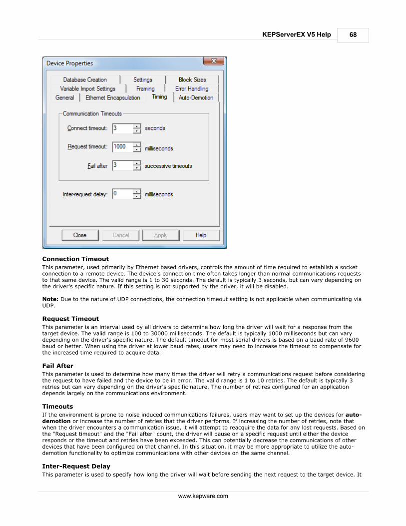
68
www.kepware.com
KEPServerEX V5 Help
Connection Timeout
This parameter, used primarily by Ethernet based drivers, controls the amount of time required to establish a socketconnection to a remote device. The device's connection time often takes longer than normal communications requeststo that same device. The valid range is 1 to 30 seconds. The default is typically 3 seconds, but can vary depending onthe driver's specific nature. If this setting is not supported by the driver, it will be disabled. Note: Due to the nature of UDP connections, the connection timeout setting is not applicable when communicating viaUDP.
Request Timeout
This parameter is an interval used by all drivers to determine how long the driver will wait for a response from thetarget device. The valid range is 100 to 30000 milliseconds. The default is typically 1000 milliseconds but can varydepending on the driver's specific nature. The default timeout for most serial drivers is based on a baud rate of 9600baud or better. When using the driver at lower baud rates, users may need to increase the timeout to compensate forthe increased time required to acquire data.
Fail After
This parameter is used to determine how many times the driver will retry a communications request before consideringthe request to have failed and the device to be in error. The valid range is 1 to 10 retries. The default is typically 3retries but can vary depending on the driver's specific nature. The number of retires configured for an applicationdepends largely on the communications environment.
Timeouts
If the environment is prone to noise induced communications failures, users may want to set up the devices for auto-demotion or increase the number of retries that the driver performs. If increasing the number of retries, note thatwhen the driver encounters a communication issue, it will attempt to reacquire the data for any lost requests. Based onthe "Request timeout" and the "Fail after" count, the driver will pause on a specific request until either the deviceresponds or the timeout and retries have been exceeded. This can potentially decrease the communications of otherdevices that have been configured on that channel. In this situation, it may be more appropriate to utilize the auto-demotion functionality to optimize communications with other devices on the same channel.
Inter-Request Delay
This parameter is used to specify how long the driver will wait before sending the next request to the target device. It

69
www.kepware.com
KEPServerEX V5 Help
will override the normal polling frequency of tags associated with the device, as well as one-shot Reads and writes. Thisdelay can be useful when dealing with devices with slow turnaround times and in cases where network load is aconcern. Configuring a delay for a device will, however, affect communications with all other devices on the channel.Thus, it is recommended that users segregate any device that requires an inter-request delay to a separate channel ifpossible. The inter-request delay has a valid range of 0 to 30000 milliseconds. The default is 0, indicating that there willbe no delay between requests with the target device. This setting will be disabled if it is not supported by the driver.For information on Inter-Request Delay support, refer to the specific driver's help documentation. Note 1: To determine when communication errors are occurring, use the device's _System Tag, _Error. Note 2: With the server's online full-time operation, these parameters can be changed at any time. Utilize the UserManager to restrict access rights to server features in order to prevent operators from changing the parameters.
Device Properties - Auto-Demotion
The Auto-Demotion parameters allow a driver to temporarily place a device off-scan in the event that a device is notresponding. By placing a nonresponsive device offline for a specific time period, the driver can continue to optimize itscommunications with other devices on the same channel. After the time period has been reached, the driver willreattempt to communicate with the nonresponsive device. If the device is responsive, the device will be placed on-scan;otherwise, it will restart its off-scan time period. Auto-demotion can be turned on by selecting the Enable auto device demotion on communication failurescheckbox in Device Properties as shown below.
There are three other parameters in the Auto-Demotion tab in Device Properties. Descriptions are as follows.
Demote after indicates how many successive cycles of request timeouts and retries will occur before the device
is placed off-scan. The valid range is 1 to 30 successive failures. The default is 3 successive failures.
Demote for indicates how long the device should be placed off-scan when the "Demote after" parameter has
been reached. During this period, no read requests will be sent to the device and all data associated with theread requests will be set to bad quality. The valid range is 100 to 3600000 milliseconds. The default is 10000milliseconds. When this period expires, the driver will place the device on-scan and allow for another attempt atcommunications.
Discard write requests during the demotion period is used to control whether or not Write requests should

70
www.kepware.com
KEPServerEX V5 Help
be attempted during the off-scan period. The default setting always sends write requests regardless of thedemotion period. If users choose to discard writes, the server will automatically fail any write request receivedfrom a client and will not post an "Unable to write..." message to the server Event Log.
Note: Users can determine when a device is off-scan by monitoring its demoted state by using the _AutoDemotedSystem Tag.
What is a Tag?
A tag represents addresses within the PLC or other hardware device with which the server communicates. The serverallows both Dynamic Tags and user-defined Static Tags. Dynamic Tags are entered directly in the OPC client and specifydevice data. User-defined Static Tags are created in the server and support tag scaling. They can be browsed from OPCclients that support tag browsing.
Displaying Tag Properties
To invoke the Tag Properties for a specific tag, double-click on it in the Tag Selection pane of the server configuration.
Tag Properties - General
A tag represents addresses in the PLC or other hardware device with which the server communicates. The server allowsboth Dynamic Tags and user-defined Static Tags. Dynamic Tags are entered directly in the OPC client and specifydevice data. User-defined Static Tags are created in the server and support tag scaling and can be browsed from OPCclients that support tag browsing. For more information, refer to Dynamic Tags and Static User-Defined Tags. Note: This dialog contains a number of features that are driven by icons.

71
www.kepware.com
KEPServerEX V5 Help
Descriptions of the parameters are as follows:
Tag Name: This parameter is used to enter the string that will represent the data available from the tag. The tag
name can be up to 256 characters in length. While using long descriptive names is generally a good idea, someOPC client applications may have a limited display window when browsing the tag space of an OPC server. Thetag name is part of the OPC browse data tag names must be unique within a given device branch or tag groupbranch. If the application is best suited for using blocks of tags with the same names, then use tag groups tosegregate the tags. For more information, refer to Tag Group Properties.
Address: This parameter is used to enter the tag's desired driver address. The address's format is based on the
driver being used. To determine how an address should be entered, click Hints. The address entered can be upto 128 characters in length. Once an address has been entered, it can be tested by clicking Check Address,which will then attempt to validate the address with the driver. If the driver accepts the address as entered, nomessage will be displayed. A popup will inform of any error. Some errors will be related to the data typeselection and not the address string.
Note: Hints provide a quick reference guide to the driver's address formats. Users can also access the driver'shelp documentation from Hints.
Description: This parameter is used to attach a comment to the tag. A string of up to 64 characters can be
entered for the description. When using an OPC client that supports Data Access 2.0 Tag Properties, thedescription parameter will be accessible from the tag's Item Description properties.
Data Type: This parameter is used to specify the format of this tag's data as it is found in the physical device. In
most cases, this is also the format of the data as it returned to the client. The data type setting is an importantpart of how a communication driver Reads and Writes data to a device. For many drivers, the data type of aparticular piece of data is rigidly fixed and the driver knows what format needs to be used when reading thedevice's data. In some cases, however, the interpretation of device data is largely in the user's hands. Anexample would be a device that uses 16 bit data registers. Normally this would indicate that the data is either aShort or Word. Many register-based devices also support values that span two registers. In these cases thedouble register values could be a Long, DWord or Float. When the driver being used supports this level offlexibility, users must tell it how to read data for this tag. By selecting the appropriate data type, the driver to isbeing told to read either one register or two or possibly a Boolean value. The driver governs the data formatbeing choosen. For specific information on available data types, click Hints to access the driver's helpdocumentation. Available data type selections are as follows:
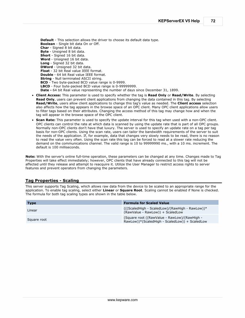
72
www.kepware.com
KEPServerEX V5 Help
Default - This selection allows the driver to choose its default data type. Boolean - Single bit data On or Off. Char - Signed 8 bit data. Byte - Unsigned 8 bit data. Short - Signed 16 bit data. Word - Unsigned 16 bit data. Long - Signed 32 bit data. DWord - Unsigned 32 bit data. Float - 32 bit Real value IEEE format. Double - 64 bit Real value IEEE format. String - Null terminated ASCII string. BCD - Two byte-packed BCD value range is 0-9999. LBCD - Four byte-packed BCD value range is 0-99999999. Date - 64 bit Real value representing the number of days since December 31, 1899.
Client Access: This parameter is used to specify whether the tag is Read Only or Read/Write. By selecting
Read Only, users can prevent client applications from changing the data contained in this tag. By selectingRead/Write, users allow client applications to change this tag's value as needed. The Client access selectionalso affects how the tag appears in the browse space of an OPC client. Many OPC client applications allow usersto filter tags based on their attributes. Changing the access method of this tag may change how and when thetag will appear in the browse space of the OPC client.
Scan Rate: This parameter is used to specify the update interval for this tag when used with a non-OPC client.
OPC clients can control the rate at which data is scanned by using the update rate that is part of all OPC groups.Normally non-OPC clients don't have that luxury. The server is used to specify an update rate on a tag per tagbasis for non-OPC clients. Using the scan rate, users can tailor the bandwidth requirements of the server to suitthe needs of the application. If, for example, data that changes very slowly needs to be read, there is no reasonto read the value very often. Using the scan rate this tag can be forced to read at a slower rate reducing thedemand on the communications channel. The valid range is 10 to 99999990 ms., with a 10 ms. increment. Thedefault is 100 milliseconds.
Note: With the server's online full-time operation, these parameters can be changed at any time. Changes made to TagProperties will take effect immediately; however, OPC clients that have already connected to this tag will not beaffected until they release and attempt to reacquire it. Utilize the User Manager to restrict access rights to serverfeatures and prevent operators from changing the parameters.
Tag Properties - Scaling
This server supports Tag Scaling, which allows raw data from the device to be scaled to an appropriate range for theapplication. To enable tag scaling, select either Linear or Square Root. Scaling cannot be enabled if None is checked.The formula for both tag scaling types are shown in the table below.
Type Formula for Scaled Value
Linear(((ScaledHigh - ScaledLow)/(RawHigh - RawLow))*(RawValue - RawLow)) + ScaledLow
Square root(Square root ((RawValue - RawLow)/(RawHigh -RawLow))*(ScaledHigh - ScaledLow)) + ScaledLow
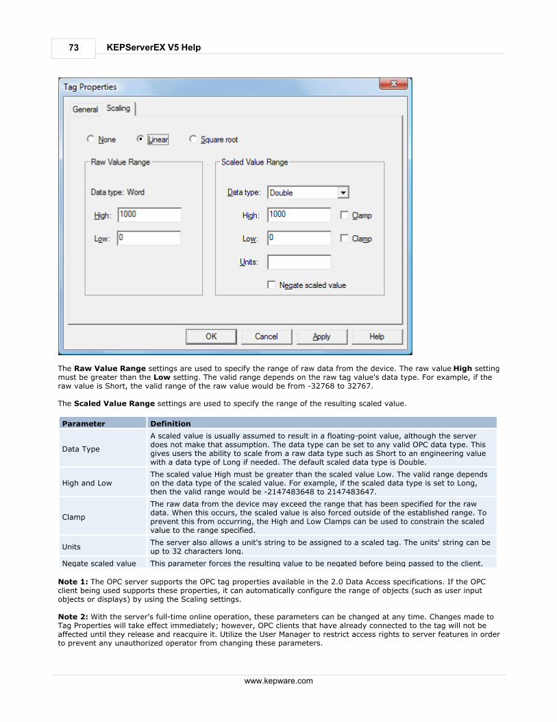
73
www.kepware.com
KEPServerEX V5 Help
The Raw Value Range settings are used to specify the range of raw data from the device. The raw value High settingmust be greater than the Low setting. The valid range depends on the raw tag value's data type. For example, if theraw value is Short, the valid range of the raw value would be from -32768 to 32767. The Scaled Value Range settings are used to specify the range of the resulting scaled value.
Parameter Definition
Data Type
A scaled value is usually assumed to result in a floating-point value, although the serverdoes not make that assumption. The data type can be set to any valid OPC data type. Thisgives users the ability to scale from a raw data type such as Short to an engineering valuewith a data type of Long if needed. The default scaled data type is Double.
High and LowThe scaled value High must be greater than the scaled value Low. The valid range dependson the data type of the scaled value. For example, if the scaled data type is set to Long,then the valid range would be -2147483648 to 2147483647.
Clamp
The raw data from the device may exceed the range that has been specified for the rawdata. When this occurs, the scaled value is also forced outside of the established range. Toprevent this from occurring, the High and Low Clamps can be used to constrain the scaledvalue to the range specified.
UnitsThe server also allows a unit's string to be assigned to a scaled tag. The units' string can beup to 32 characters long.
Negate scaled value This parameter forces the resulting value to be negated before being passed to the client.
Note 1: The OPC server supports the OPC tag properties available in the 2.0 Data Access specifications. If the OPCclient being used supports these properties, it can automatically configure the range of objects (such as user inputobjects or displays) by using the Scaling settings. Note 2: With the server's full-time online operation, these parameters can be changed at any time. Changes made toTag Properties will take effect immediately; however, OPC clients that have already connected to the tag will not beaffected until they release and reacquire it. Utilize the User Manager to restrict access rights to server features in orderto prevent any unauthorized operator from changing these parameters.

74
www.kepware.com
KEPServerEX V5 Help
Dynamic Tags
Dynamic Tag addressing is a second method of defining tags. Dynamic Tags allow users to define tags solely in theclient application. Thus, instead of creating a tag item in the client that addresses another tag item created in theserver, users only need to create tag items in the client that directly accesses the device driver's addresses. On clientconnect, the server will create a virtual tag for that location and will start scanning for data automatically. To specify an optional data type, append one of the following strings after the '@' symbol:
Byte
Char
Short
Word
Long
DWord
Float
Double
BCD
LBCD
String
If the data type is omitted, the driver will choose a default data type based on the device and address that is beingreferences. The default data types for all locations are documented in each individual driver's help documentation. Ifthe data type specified is not valid for the device location, the server will not accept the tag and an error will be postedin the Event Log window.
OPC Client Using Dynamic Addressing Example
Scan the 16-bit location 'R0001' on the Simulator device. The following Dynamic Tag examples assume that the projectcreated is part of the example.
1. Start the OPC client application and connect to the server.
2. Using the Simulator driver, create a channel and name it Channel1. Then, make a device and name it Device1.
3. In the client application, define an item name as Channel1.Device1.R0001@Short.
4. The client project will automatically start receiving data. The default data type for address R0001 in the Simulatordevice is Word. To override this, the @Short has been appended to select a data type of Short.
Note: When utilizing Dynamic Tags in an OPC client application, the use of the @[Data Type] modifier is not normallyrequired. OPC clients can specify the desired data type as part of the request when registering a link for a specific dataitem. The data type specified by the OPC client will be used if it is supported by the communications driver. The @[DataType] modifier can be useful when ensuring that a communications driver interprets a piece of data exactly as needed.
Non-OPC Client Example
Non-OPC clients can override the update rate on a per-tag basis by appending @[Update Rate]. For example, appending "<DDE service name>|_ddedata!Device1.R0001@500" will override just the update rate. "<DDE service name>|_ddedata!Device1.R0001@500,Short" will override both update rate and data type. See Also: Static Tags (User-Defined) and Designing a Project: Adding User-Defined Tags. Note 1: For every device in a project that can be used by a client to determine whether a device is functioningproperly, the server creates a special Boolean tag. To use this tag, specify the item in the link as Error. The value ofthis tag is zero if the device is communicating properly; otherwise, it is one. Note 2: If device address is used as the item of an link such that the address matches the name of a user-defined tagin the server, the link will reference the address pointed to by the user-defined tag. Note 3: Static Tags must be used in order to scale data in the server.
Static Tags (User-Defined)
The most common method that uses the server to get data from the device to the client application has two
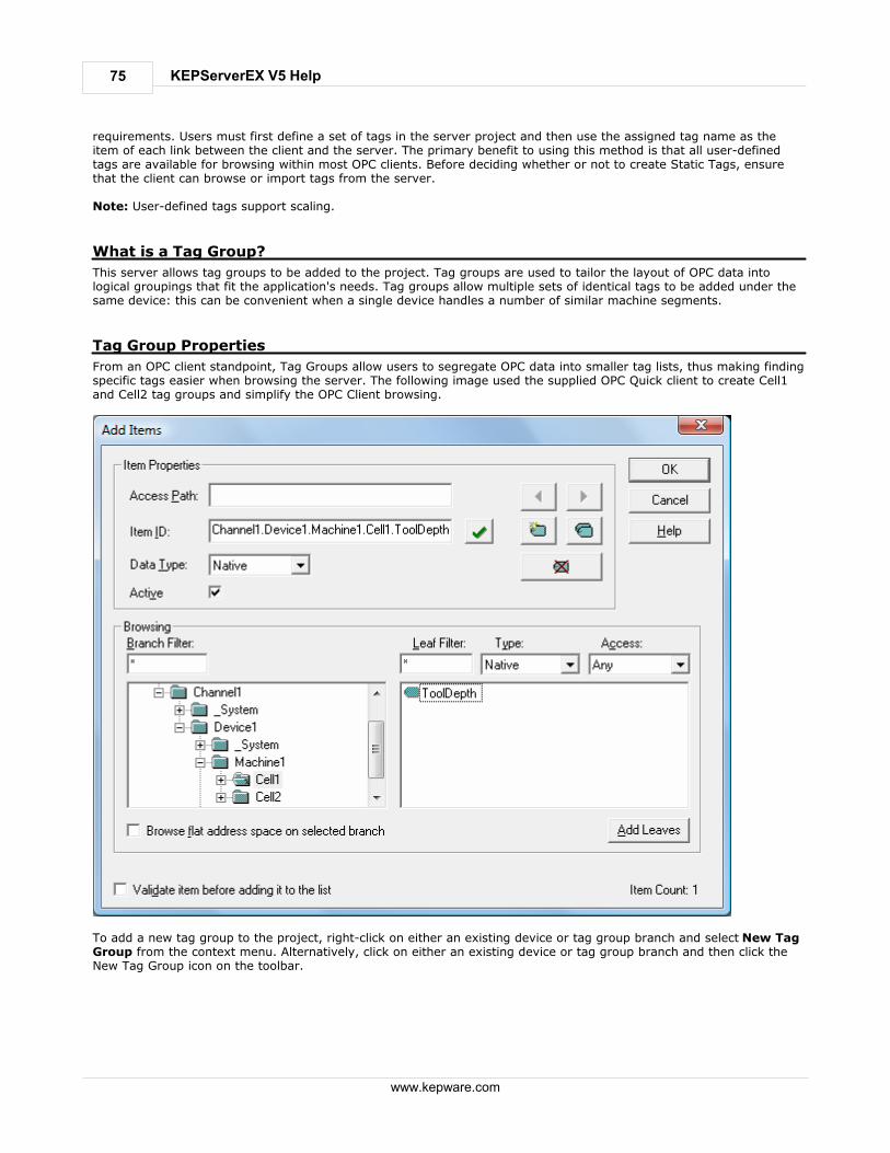
75
www.kepware.com
KEPServerEX V5 Help
requirements. Users must first define a set of tags in the server project and then use the assigned tag name as theitem of each link between the client and the server. The primary benefit to using this method is that all user-definedtags are available for browsing within most OPC clients. Before deciding whether or not to create Static Tags, ensurethat the client can browse or import tags from the server. Note: User-defined tags support scaling.
What is a Tag Group?
This server allows tag groups to be added to the project. Tag groups are used to tailor the layout of OPC data intological groupings that fit the application's needs. Tag groups allow multiple sets of identical tags to be added under thesame device: this can be convenient when a single device handles a number of similar machine segments.
Tag Group Properties
From an OPC client standpoint, Tag Groups allow users to segregate OPC data into smaller tag lists, thus making findingspecific tags easier when browsing the server. The following image used the supplied OPC Quick client to create Cell1and Cell2 tag groups and simplify the OPC Client browsing.
To add a new tag group to the project, right-click on either an existing device or tag group branch and select New TagGroup from the context menu. Alternatively, click on either an existing device or tag group branch and then click theNew Tag Group icon on the toolbar.

76
www.kepware.com
KEPServerEX V5 Help
When adding a new tag group to the project, users will be presented with the following dialog.
Tag groups can be added at any level from the device-level down, and multiple tag groups can be nested together to fitthe application's needs. As seen in the OPC Quick Client dialog above, the fully qualified OPC item path is "Channel1.Device1.Machine1.Cell1.Tag1". For this OPC item, "Machine1" and "Cell1" segments are nested tag groups. Note: With the server's online full-time operation, these parameters can be changed at any time. Any changes made tothe tag groups will take effect immediately. If the name is changed, OPC clients that have already used that tag groupas part of an OPC item request will not be affected until they release the item and attempt to reacquire it. New taggroups added to the project will immediately allow browsing from an OPC client. Utilize the User Manager to restrictaccess rights to server features in order to prevent operators from changing the parameters.
What is the Alias Map?
The Alias Map provides both a mechanism for backwards compatibility with legacy server applications as well as a wayto assign simple alias names to complex tag references. This is especially useful in client applications that limit the sizeof tag address paths. Although the latest version of the server will automatically create the alias map, users can addtheir own alias map entries to compliment those created by the server. Users can also filter the server created aliasesso that the only ones visible are their own. Alias Map elements can be added, edited, deleted, exported and imported by clicking on the appropriate icon buttons inthe Alias Map window. The Alias Properties dialog allows an alias to be added or edited. The image below displays thevarious alias map entries generated for the server project.
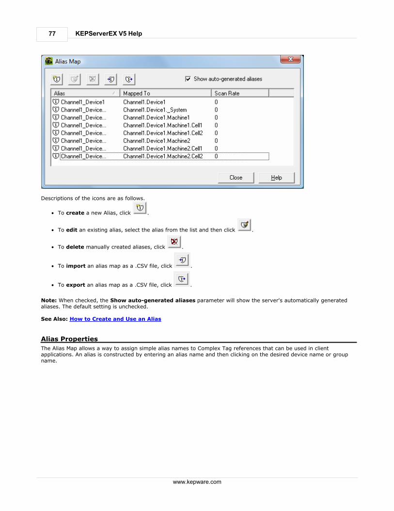
77
www.kepware.com
KEPServerEX V5 Help
Descriptions of the icons are as follows.
To create a new Alias, click .
To edit an existing alias, select the alias from the list and then click .
To delete manually created aliases, click .
To import an alias map as a .CSV file, click .
To export an alias map as a .CSV file, click .
Note: When checked, the Show auto-generated aliases parameter will show the server's automatically generatedaliases. The default setting is unchecked. See Also: How to Create and Use an Alias
Alias Properties
The Alias Map allows a way to assign simple alias names to Complex Tag references that can be used in clientapplications. An alias is constructed by entering an alias name and then clicking on the desired device name or groupname.

78
www.kepware.com
KEPServerEX V5 Help
Descriptions of the Alias Properties are as follows.
Alias Name: This parameter is used to enter the alias name, which can be up to 256 characters long. It must be
unique in the alias map.
Mapped To: This parameter specifies the location of the Alias. Because the alias map does not allow tag items to
be browsed from the alias table, users should create a simple name that replaces the address that leads up tothe tag. This will make is easier to address items in a client application that does not support tag browsing.
Scan rate override: This selection is used to specify an update rate that will be applied to all DDE/FastDDE/
SuiteLink and most other non-OPC tags accessed using this alias map entry. This setting is equivalent to theTopic update rate found in many DDE only servers. The valid range is 0 to 99999990 milliseconds. The default is0 milliseconds. When set to 0 milliseconds the server will observe the DDE scan rate set at the individual taglevel using the Tag Properties - General dialog.
Show system tag groups: When checked, this parameter will display the channel and device level _System tag
groups. The default setting is unchecked.
Once the desired path has been selected and the DDE scan rate has been set, click OK to complete the alias. To entermore alias map elements, return to the Alias Map dialog.
What is the Event Log?
The Event Log displays the date, time and source of an information, warning or error event. For more information,select a link from the list below. Event Log Display
Event Log Page Setup
See Also: Components
Event Log Display
The Event Filter helps users tailor the Event Log's contents to meet the application's reporting requirements. There arecurrently three types of messages that can be recorded in the Event Log: General Messages, Warnings and Errors.General messages include server startup and shutdown messages; Warnings include messages such as device notresponding; Errors include messages such as the rejection of bad OPC item request.

79
www.kepware.com
KEPServerEX V5 Help
Users can access the Event Filter in the Configuration Client by clicking Tools | Event Log | Event Filter.Alternatively, users can also right-click anywhere in the Event Log display and then select Event Filter.
Figure 1: Accessing through the Tools menu
Figure 2: Accessing through the context menu Note: The Event Log system would be useless if there was no mechanism to protect its contents. If operators couldchange these parameters or reset the log, the purpose would be lost. Utilize the User Manager to limit the functions anoperator can access and prevent these actions from occurring. See Also: Settings - Event Log
Event Log Page Setup
Event Log Printing and Setup
The Event Log's print content and appearance can be customized by selecting Tools | Event Log | Page Setup.Options for modification include margin size, font and event details. To preview the changes, click Tools | Event Log |Print Preview.

80
www.kepware.com
KEPServerEX V5 Help
Descriptions of the parameters are as follows.
The Margin parameter sets the distance from the edge of the Event Log's printed page to the top, bottom, left
and right. All margin settings are entered in inches.
The Fonts parameter selects a font to be used as the header and footer text, as well as for the actual Event Log
records. Only fixed space fonts will appear in the Fonts dialog. To change a font, simply click on the changebutton. When invoked, the standard font selection dialog will be displayed. The default settings are shown in theimage above.
The Print Options parameter selects which fields will be included in the print output. If all options are
deselected, the resulting output will only contain a list of event descriptions.
The Print separator lines option forces a single line to be drawn between each group of five event records on
the resulting Event Log printout.
Designing a Project
Although this server is designed for easy usage, there are several steps required to create, configure and run a project.Utilize the server's User Interface to build a project, starting by selecting the specific communications driver,configuring its parameters and then adding user-defined tags as necessary. Before beginning, refer to SystemRequirements. The following steps provide guidance on the process of building a project. Throughout this example, a number ofadditional help links will be presented in order to provide supplemental information. Use the Back button on the helpsystem's toolbar to return to the example. Select a link below to jump to a specific page. Running the Server
Starting a New Project
Adding and Configuring a Channel
Adding and Configuring a Device

81
www.kepware.com
KEPServerEX V5 Help
Adding User-Defined Tags
Adding Tag Scaling
Saving the Project
Testing the Project
Note: The examples in the following pages use the Simulator driver supplied with the server. The Simulator driver is amemory-based driver that provides both static and changing data for demonstration purposes. The Simulator driverdoes not have the broad range of configuration options found in many other communication drivers; thus, someexamples may require additional screen shots to demonstrate specific product features that are present when using oneof the normal communication drivers. In these cases, screen shots will be provided.
Running the Server
Although this server runs as a service by default, users can choose to run it on the desktop. When running as a service,the server is online all the time. When running as a desktop application, the OPC client can automatically invoke theserver when it attempts to connect and collect data. In order for either process to occur correctly, users must firstcreate and configure a project. When invoked, the server automatically selects the most recently used project. Initially, however, users need to manually invoke the server using the desktop icon, the Windows Start menu or byselecting Configuration in Administration on the System Tray. The image below displays the invoked interface(although its appearance may differ depending on any changes that may have been made). For more information onthe Configuration's elements, refer to Basic Server Components.
Note: Now that the server is running, a project may be created.
Starting a New Project
This server must be configured to determine what content it will provide while operating. For a server project, thecontent that is determined will define channels, devices, optional tag groups and tags. These factors exist in the contextof a project file. As with many applications, users can define a number of project files and save and load them asneeded. Most of the configuration needed within the server is contained within a project file; however, there are also a numberof configuration options that are global and are applied to all projects. These global options are configured in the Tools| Options menu. Options include General Options, Runtime Connection Options, Event Logger Options, OPC Optionsand Compliancy Options. Furthermore, all global options are stored in a Windows INI file called "Servermain.INI" andset in the Windows registry. This file is located in the server's root directory. While it is normal practice to store global
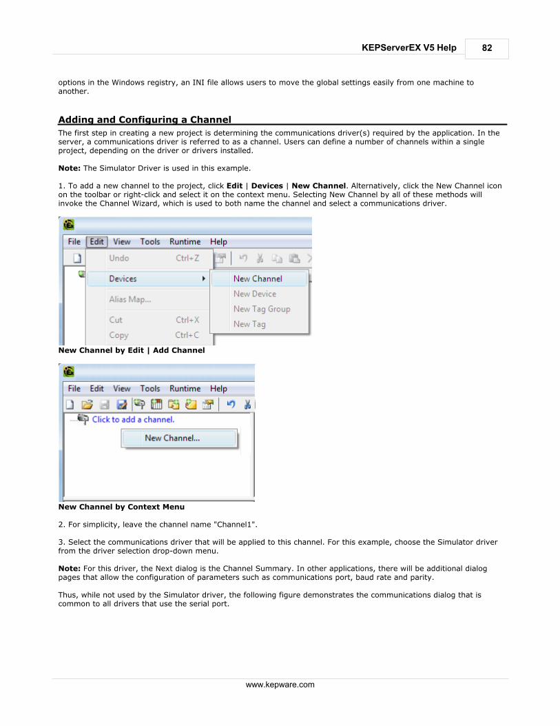
82
www.kepware.com
KEPServerEX V5 Help
options in the Windows registry, an INI file allows users to move the global settings easily from one machine toanother.
Adding and Configuring a Channel
The first step in creating a new project is determining the communications driver(s) required by the application. In theserver, a communications driver is referred to as a channel. Users can define a number of channels within a singleproject, depending on the driver or drivers installed. Note: The Simulator Driver is used in this example. 1. To add a new channel to the project, click Edit | Devices | New Channel. Alternatively, click the New Channel iconon the toolbar or right-click and select it on the context menu. Selecting New Channel by all of these methods willinvoke the Channel Wizard, which is used to both name the channel and select a communications driver.
New Channel by Edit | Add Channel
New Channel by Context Menu 2. For simplicity, leave the channel name "Channel1". 3. Select the communications driver that will be applied to this channel. For this example, choose the Simulator driverfrom the driver selection drop-down menu. Note: For this driver, the Next dialog is the Channel Summary. In other applications, there will be additional dialogpages that allow the configuration of parameters such as communications port, baud rate and parity. Thus, while not used by the Simulator driver, the following figure demonstrates the communications dialog that iscommon to all drivers that use the serial port.

83
www.kepware.com
KEPServerEX V5 Help
4. To complete the addition of the channel, click Next | Finish. Important: A a small red "x" should be visible below the channel icon. This denotes that the channel does not containa valid configuration because no devices have been added yet. See Also: How to... Optimize the Server Project and Server Summary Information.
Adding and Configuring a Device
Once a channel has been defined in a project, a device must then be added to the channel. A device identifies thephysical node or station on a communications link. A device can also be thought of as a way of framing the definition ofa connection to a specific point of interest in the application. In this respect, a device would still be used as a termwhen describing the connection to a database object. In this example, "device" refers to a specific device on a network.In the Simulator driver, a device supports multiple device nodes and allows users to simulate networked devices. 1. To add a device, select the channel to which the device will be added. Next, click Edit | New Device. Alternatively,click the Add Device icon on the toolbar or right-click and select Add Device from the context menu. Selecting NewDevice by all of these methods will invoke the Device Wizard, which is used to both name the device and set its NodeID.
New Device by Edit | New Device

84
www.kepware.com
KEPServerEX V5 Help
New Device by Context Menu 2. For simplicity, leave the device name "Device1". Note: The number of dialog pages in the Device Wizard depends on the driver being used in the application. 3. Click Next to proceed to the next dialog. Then, select either a 16 bit or 8 bit register size for the device beingsimulated. In other device drivers, users would select a device model. For this example, however, choose the 16 bitdevice size. 4. Then select the Device ID, which is the unique identifier required by the actual communications protocol. For theSimulator driver, the Device ID is a numeric value. The format and style of the Device ID depends on thecommunications driver being used. Note: For this driver, the next dialog is the Device Summary. In other applications, there will be additional dialog pagesthat allow the configuration of parameters such as device timeout and retry count. Thus, while not used by the Simulator driver, the following figure demonstrates the Timeout dialog that is common toall communications drivers.

85
www.kepware.com
KEPServerEX V5 Help
5. To complete the addition of the device, click Next | Finish. Note: The server is now ready to start providing data to OPC clients. With the server's online full-time mode ofoperation, the server can start providing OPC data immediately. At this point, however, the configuration can potentiallybe lost since the project has not yet been saved. Before saving, users can add tags to the server. For more information,refer to Adding User-Defined Tags.
Adding User-Defined Tags
There are two ways to use the server to get data from a device to the client application. The first and most commonmethod requires that users first define a set of tags in the server project and then use the name previously assigned toeach tag as the item of each link between the client and the server. This method makes all user-defined tags availablefor browsing within OPC clients. User-defined tags also support scaling. See Also: Adding Tag Scaling. 1. To add a tag to the project, first select a device name from the Channel/Device tree view within the server. The Tagdialog below uses the example project and has "Device1" as the currently selected device. 2. Next, click Edit | New Tag. Alternatively, right-click on the device and select Add Tag from the Context Menu orclick the toolbar's Add Tag icon. Selecting Add Tag by all of these methods will invoke Tag Properties - General, a dialogin which users set the tag name, specify a device-specific address, select a data type and set the tag's access method.Before continuing, refer to Tag Properties - General for terminology.

86
www.kepware.com
KEPServerEX V5 Help
Add Tag by Edit | New Tag
Add Tag by Context Menu 3. Edit the controls to match the following content (as shown in the Tag dialog image).
Tag Name: MyFirstTag
Address: R000
Description (Optional): My First Simulator Tag
Data Type: Word
Client Access: Read/Write
Scan Rate: 100 milliseconds*
*This does not apply for OPC tags. Note: The Address, Data Type and Client Access fields depend on the communications driver being used. With theSimulator driver, "R000" is a valid address. The address "R000" supports a data type of "Word" and client access rightsof "Read/Write;" however, this will obviously not be the case with every communications driver. To aid users indetermining the correct settings for their driver, there is the Hints function. To use Hints, click on the question markicon in Tag Properties. This will invoke the driver-specific tag information (such as available addresses and data types).For the Simulator driver, Hints appears as follows.

87
www.kepware.com
KEPServerEX V5 Help
For additional information, click the Help button in the Hints dialog. This invokes the driver specific help documentationat the page that covers data addressing for the device currently selected. 4. Commit the tag to the server by pressing Apply in Tag Properties - General. The tag should now be visible in the TagView area of the server. If only one tag needed to be added, users would be finished at this point. For this example,however, a second tag needs to be added for use in Tag Properties - Scaling. 5. If Apply has already been pressed, click the New icon in Tag Properties - General. This clears all of the fields andreturns them to their default state. Enter the following data:
Tag name: MySecondTag
Address: K000
Description: My First Scaled Tag
Data Type: Short
Client Access: Read/Write
Scan rate: (Doesn't Apply)
6. Next, press Apply to commit the second tag. Note: When entering tag information, users can and will be presented with an occasional error message. The errormessages presented will be generated by either the server or the driver. The server will generate error messages whenusers attempt to add a tag using the same tag name as an existing tag. The communications driver will generate errorsfor three possible reasons:
1. If there are any errors entered in the format or content of the address field, including errors in the address rangeof a particular device specific data item.
2. When the data type selected is not available for the address that has been entered.
3. If the client access level chosen is not available for the address that has been entered.
In each of these cases, the error message will be specific in describing the error. The error message will also providethe option of directly invoking the driver specific help documentation in order to help remedy the problem.
Dynamic Tag Addressing
Dynamic Tag Addressing is another way of defining tags. Dynamic tags are used to define tags solely in the clientapplication. Instead of creating a tag item in the client that addresses another tag item that has been created in theserver, users only need to create a tag item in the client that directly accesses the device address. Note 1: The server creates a special Boolean tag for every device in a project that can be used by a client to determinewhether that device is functioning properly. To use this tag, specify the item in the link as Error. The value of this tag iszero if the device is communicating properly; otherwise, it is one. Note 2: If a device address is used as the item of a link, such that the address matches the name of a user-defined tagin the server, the link will reference the address pointed to by the user-defined tag. Furthermore, with the server'sonline full-time operation, users can technically begin using this project in an OPC client at this moment. For the sake ofwork preservation, proceed to Saving and Testing the Project.

88
www.kepware.com
KEPServerEX V5 Help
Adding Tag Scaling
When defining a new tag in the server, users have the option of applying tag scaling, which allows raw data from thedevice to be scaled to an appropriate range for the application. There are two types of scaling: Linear and Square Root.For more information, refer to Tag Properties - Scaling. Note: The image below uses the second tag previously developed in this example. The Tag Properties - General dialogshould appear as shown below.
1. To add scaling to this tag, click on the Scaling tab to open the Scaling Properties. Then edit the content of the dialogto match the following.

89
www.kepware.com
KEPServerEX V5 Help
2. In this example, Linear Scaling has been selected. The raw value range allows users to specify what they expect toreceive as a data range from the actual device. The scaled data type also allows users to specify how the resultingscaled value is presented to the OPC client application. The scaled value range is used to specify the desired range inengineering units for the resulting value. By applying the high and low clamps, users can ensure that their output willalways stay within the configured limits. This may not always be the case. If the raw data exceeds the range set by theraw value High and Low, it forces the scaled value beyond the range that has been entered for the scaled value. Theclamps prevent this from occurring. 3. The Units field allows users to provide a string to the OPC client that describes the format or unit for the resultingengineering value. In order to use the Units field, an OPC client that can access the Data Access 2.0 tag properties datais required. If the client does not support these features, there is no need to configure the Units field. 4. Once the data has been entered as shown above, click OK or Apply to commit the scaling changes.
Dynamic Addressing
Dynamic Tag Addressing is the second method for defining tags. Dynamic tags are used to define tags solely in theclient application. Instead of creating a tag item in the client that addresses another tag item created in the server,users only need to create tag items in the client that directly accesses the device driver's addresses. On client connect,the server will create a virtual tag for that location and start scanning for data automatically. Note: If the data type is omitted, the driver will choose a default data type based on the device and address beingreferenced. The default data types for all locations are documented in the individual driver help documentation. If thedata type specified is not valid for the device location, the server will not accept the tag and an error will be posted inthe Event Log window.
Saving the Project
If each step in this example has been followed correctly, there should now be a project configured with two user-defined tags that are ready to be saved. How the project is saved varies and depends on whether a Runtime projector an offline project is being edited. When editing projects in the Runtime, the server's online full-time operation allows tags to be accessed immediatelyfrom an OPC client once it has been saved to disk. The changes are made to the actual project, so users save by
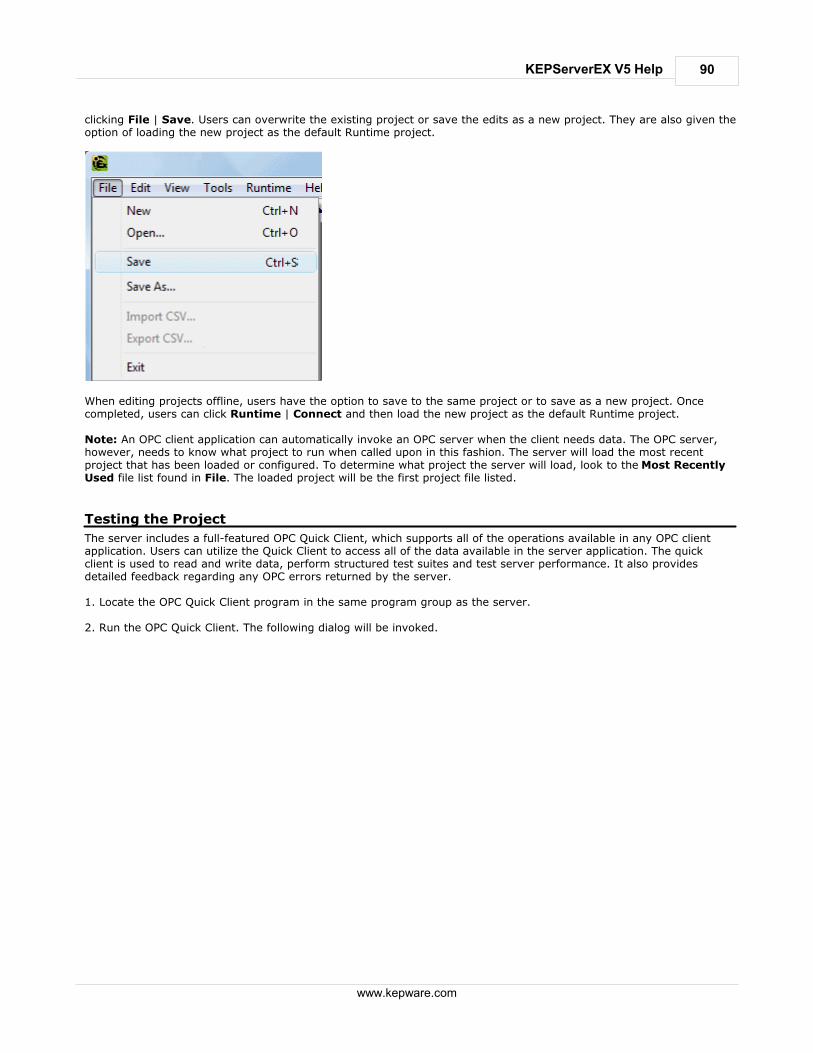
90
www.kepware.com
KEPServerEX V5 Help
clicking File | Save. Users can overwrite the existing project or save the edits as a new project. They are also given theoption of loading the new project as the default Runtime project.
When editing projects offline, users have the option to save to the same project or to save as a new project. Oncecompleted, users can click Runtime | Connect and then load the new project as the default Runtime project. Note: An OPC client application can automatically invoke an OPC server when the client needs data. The OPC server,however, needs to know what project to run when called upon in this fashion. The server will load the most recentproject that has been loaded or configured. To determine what project the server will load, look to the Most RecentlyUsed file list found in File. The loaded project will be the first project file listed.
Testing the Project
The server includes a full-featured OPC Quick Client, which supports all of the operations available in any OPC clientapplication. Users can utilize the Quick Client to access all of the data available in the server application. The quickclient is used to read and write data, perform structured test suites and test server performance. It also providesdetailed feedback regarding any OPC errors returned by the server. 1. Locate the OPC Quick Client program in the same program group as the server. 2. Run the OPC Quick Client. The following dialog will be invoked.

91
www.kepware.com
KEPServerEX V5 Help
Establishing a Connection
3. Next, establish a connection by clicking Edit | New Server Connection. Alternatively, right-click and select NewServer Connection from the Context Menu or click the New Server icon on the toolbar. Selecting New Server Connectionby all of these methods will invoke the OPC Server Selection dialog, which is used to make connections with an OPCServer either locally or remotely via DCOM.
Connect to Server by Edit | New Server Connection

92
www.kepware.com
KEPServerEX V5 Help
Connect to Server by the Context Menu Note 1: By default, the Server Selection dialog is configured with the Prog ID of the server. The name listed in theserver connection dialog is called the Prog ID of the server. OPC clients use this name to reference a specific OPCserver. The server connection dialog should appear as shown below.
Note 2: Once a connection is made, two things may happen. If the server is running, the OPC Quick Client will simplymake a connection to the server. If the server is not running, it will start up automatically.
Adding a Group
4. Next, add a group needs to the connection. To do so, select the server connection and then click Edit | New Group.Alternatively, right-click and select New Group from the context menu or click the New Group icon on the toolbar.Selecting New Group by all of these methods will invoke the Group Properties dialog, which is used to configure how thegroup interacts with the OPC server. Note: Groups act as a container for any tags that will be accessed from the server. All OPC clients use groups to accessOPC server data. Aside from providing a container for lists of tags, OPC groups also provide control over how tags areupdated. There are a number of properties attached to a group that allow the OPC client to determine how often datashould be read from the tags, whether the tags are active or inactive, whether a dead band applies and etc. Theseproperties let the OPC client control how the OPC server operates. For more information on Group Properties, refer tothe OPC Quick Client help documentation.

93
www.kepware.com
KEPServerEX V5 Help
Adding a Group by Toolbar Icon
Adding a Group by Context Menu 5. For the purposes of this example, edit the Group Properties parameters so that they match the following image.
Note: The Update Rate, Percent Dead Band and Active State parameters control when and if data will be returnedfor the group's tags. The Update Rate determines how often data will be scanned from the actual device. Itdetermines how often data will be returned to the OPC client as a result of that scan. The Percent Dead Band is used

94
www.kepware.com
KEPServerEX V5 Help
to eliminate or reduce noise content in the data by only detecting changes when they exceed the percentage changethat has been requested. The percent change is a factor of the data type of a given tag. The Active State is used toturn all of the tags in this group either on or off. The Group Name is used for reference from the client and canactually be left blank. 6. Press OK to commit the group when finished.
Accessing Tags
7. OPC server tags must be added to the group before they can be accessed. OPC Data Access specifications defines atag browsing interface as one that allows an OPC client to directly access and display the available tags in an OPCserver. By allowing the OPC client application to browse the tag space of the OPC server, a user can simply click on thedesired tags to automatically add them to a group. 8. Select the group in which tags will be placed. Then, click Edit | New Item. Alternatively, right-click and select NewItem from the Context Menu or click the New Server icon in the toolbar. Selecting New Item from all of these methodswill invoke the Add Items dialog, which is used to enter an Item ID, Data Type and Active State for an OPC item
Note: The Add Items dialog also provides a tree view of the Browsing section and can be used to browse into an OPCserver to find tags configured at the server. Using the "Example1" project created as part of this example, users canaccess the tags previously defined by expanding the branches of the view. 9. Once the tree hierarchy is at the point shown in the image above, users can begin adding tags to the OPC group bydouble-clicking on the tag name. As tags are added to the group, the Item Count shown at the bottom of the AddItems dialog will increase to indicate the number of items being added. If both "MyFirstTag" and "MySecondTag" wereadded, the item count should be 2. 10. When finished, commit the tags to the group by clicking OK. Note: Users should now be able to access data from the server using the two tags that were defined. The OPC Quick

95
www.kepware.com
KEPServerEX V5 Help
Client should appear as shown below.
The first tag, "MyFirstTag," should contain a changing value. The second tag should be zero at this point. If users onlyneeded to test the reading of an OPC item, they are now finished. If, however, users desired to change an OPC item,they can use one of the write methods to send new data to the OPC item.
Writing Data to the OPC Server
The OPC Quick Client supports two methods for writing data to an OPC server: Synchronous Writes andAsynchronous Writes. Synchronous Writes perform a write operation on the OPC server and wait for it tocomplete. Asynchronous Writes perform a write on the OPC server but doesn't wait for the write to complete. Userscan choose either method when writing data to an OPC: the different write methods are more of a factor in OPC clientapplication design. 11. To write to an OPC item, first select the item and right-click to display its context menu. Then, select eitherSynchronous or Asynchronous Writes. Both choices will invoke the Write Dialog. For the purpose of this example, right-click on "MyFirstTag" and select Asynchronous Write.
Note: Although the Write Dialog is displayed, the value will continue to update. Users can enter a new value in for thisitem by clicking in the item's Write Value and then entering a different value. Once completed, the Apply button willbecome active. Press Apply to write the data. Apply allows users to continue to write new values: OK writes the newvalue but also closes the dialog. Thus, once users are finished making changes, they can exit the dialog by pressing OK

96
www.kepware.com
KEPServerEX V5 Help
. If no new data has been entered, clicking OK will not send data to the server.
Conclusion
At this point, all of the basic steps involved in building and testing an OPC project have been discussed. Users areencouraged to continue to test various features of both the server and the OPC Quick Client for greater understandingand comprehension. For more information on the OPC Quick Client, refer to its help documentation. If the basic terminology and concepts are understood, users can begin developing their OPC application. If using VisualBasic, please refer to the supplied example projects. These two projects provide both a simple and complex example ofhow OPC technology can be used directly in Visual Basic applications.
New Channel - Identification
This server supports the use of simultaneous multiple communications drivers. Each protocol or driver used in a projectis called a Channel, which refers to a specific communications driver. A server project can consist of many channels,each with either unique communications drivers or with the same. A channel acts as the basic building block of an OPClink. Its properties control parameters such as communications port, baud rate and parity.
In a server project, each Channel Name must be unique and can be up to 256 characters long. Although usingdescriptive names is usually a good idea, some OPC client applications may have a limited display window whenbrowsing the tag space of an OPC server. Note: The channel name entered will be part of the OPC browser information.
New Channel - Device Driver
After a name has been entered for the new channel, a communications driver must be selected from the "Devicedriver:" drop-down list. The drop-down list's contents depend on the communications drivers currently installed on thePC. The list will contain the drivers available for use in the server project.

97
www.kepware.com
KEPServerEX V5 Help
Since the server supports the use of simultaneous multiple communications drivers, users can add a number ofchannels to the project. It is not necessary to select a different communications driver for each channel. Many of thecommunications drivers available for the server support operation on either multiple communications ports or acrossmultiple network connections. If the driver chosen does not support multiple channels (or if the number of supportedchannels has been exceeded) the driver will display a dialog stating so. Another server feature is the ability to run Channel Diagnostics. Users can select the Enable Diagnostics check boxin order to make diagnostic information available to the OPC application. When diagnostic functions are enabled, Diagnostic Tags will be available for use within client applications. A Diagnostic Window will also be available whenthis feature is enabled.
New Channel - Communications
After a device driver has been selected, suers need to set up its communications. The server supports several mediumsfor communications; thus, the Communications dialog's format will vary depending on the driver's requirements.

98
www.kepware.com
KEPServerEX V5 Help
For Serial based drivers, the Communications dialog is used to set the Serial Port, Baud rate, Data bits, Parity, Stop bitsand RTS/DTR Flow Control. Note: The dialog's additional options allow users to select and use dial-up Modem support or Ethernet Encapsulation forconnecting to devices via Serial to Ethernet terminal servers. For more information, refer to Using a Modem in theServer Project and Device Properties - Ethernet Encapsulation.
New Channel - Summary
The Channel Summary dialog allows users to review the selections they have made while defining the channel. If amistake is found upon review, users can simply click the Back button until the required dialog is displayed. Aftermaking changes, users can click the Next button to return to the Summary page. Once satisified with the ChannelSummary, click Finish.

99
www.kepware.com
KEPServerEX V5 Help
New Device - Name
A Device Name can be the same from one channel to the next; however, each device under a channel must have aunique name. The Device Name is a user-defined logical name for the device that can be up to 256 characters long.While long descriptive names are generally good, some OPC client applications may have a limited display window whenbrowsing the tag space of an OPC server. Note: The device name and channel name are part of the browse tree information.

100
www.kepware.com
KEPServerEX V5 Help
Note: Within an OPC client, the combination of channel name and device name would appear as ChannelName.DeviceName.
New Device - Model
The Model parameter is used to select the device model associated with the Device ID. The Model selection drop-downmenu's contents will vary depending on the chosen communication driver. If a driver does not support model selection,this option will be unavailable. If the communication driver does support multiple models, users should match the modelselection to the physical device. If the device being used is not represented in the model drop-down list, select a modelthat conforms closest to the target device. This can be determined from the specific driver's help documentation. Note: Some drivers support an Open model, which allows users to communicate without knowing the target device'sspecific details.

101
www.kepware.com
KEPServerEX V5 Help
Note: With the server's online full-time operation, these parameters can be changes at any time. If the communicationsdriver supports multiple device models, the model selection can only be changed if there are currently no clientapplications connected to the device. Since the device is being added at this time, any model can be selected. Utilizethe User Manager to restrict access rights to server features and prevent operators from changing parameters.
New Device - ID
The Device ID parameter is used to specify a device's driver-specific station or node. The type of ID entered will varydepending on the communication driver being used. For example, many communication drivers use a numeric value. Asshown in the image below, when a driver supports a Numeric ID, the menu option allows users to enter a numericvalue. The numeric value's format can be changed to suit the needs of either the application or the communicationdriver's characteristics. The format is set by the driver by default. Possible formats include Decimal, Octal andHexadecimal.

102
www.kepware.com
KEPServerEX V5 Help
If the communications driver is either Ethernet-based or supports an unconventional station or node name, the dialogshown below may be displayed. In this case, the Device ID is a TCP/IP ID. TCP/IP or UDP IDs consist of four valuesseparated by periods. Each value has a range of 0 to 255. Some Device IDs are string based. Note: Depending on the communications driver being used, there may be more parameters that need to be defined inthe New Device - ID dialog. For more information on the driver's Device ID, refer to its help documentation.

103
www.kepware.com
KEPServerEX V5 Help
Note: With the server's online full-time operation, these parameters can be changed at any time. Any changes made tothe Device ID will take effect immediately. Utilize the User Manager to restrict access rights to server features andprevent operators from changing parameters.
New Device - Timing
Device Timing parameters allow a driver's response to error conditions to be tailored to the application's needs. Theenvironment in which the application runs may require changes to the timing parameters. Factors such as electricallygenerated noise, modem delays and bad physical connections can all influence how many errors or timeouts acommunications driver may encounter. The timing parameters are specific to each configured device.
Note: For most projects, the default Timeout settings work well. If users find that the project takes too long to time outa device or that there are too many timeouts, they can adjust the settings to improve performance.
New Device - Summary
The Device Summary page allows users to review the selections that have been made for the device. If a mistake isfound upon review, users can simply click the Back button until the required dialog is displayed. After making changes,users can click the Next button to return to the Summary page. Once satisified with the Device Summary, click Finish.

104
www.kepware.com
KEPServerEX V5 Help
Server Options
Server options are configured on a per-user basis. For more information on a specific dialog, select a link from the listbelow. Options - General
Options - Runtime Connections
Options - General
This dialog is used to specify general server options, such as when to establish a connection with the Runtime, when toback up saved Configuration project files and what conditions will invoke warning pop-ups. For more information, referto the descriptions below.

105
www.kepware.com
KEPServerEX V5 Help
Descriptions of the parameters are as follows:
Immediately attempt to establish a Runtime connection on start: This parameter is used to specify
whether the configuration tool will connect to the Runtime when started. It is checked by default. If it isunchecked, users must manually connect.
Keep track of the __ most recently used project files: This parameter is used to specify how many project
files will be presented on the MRU (Most Recently Used) list of projects. The valid range is 1 to 16.
Backup saved Configuration project files prior to overwriting: Select this check box in order to have the
system automatically make a backup copy of the last saved Configuration project before overwriting it with a newproject file. The backup file's name and location will be displayed in the Event Log.
CSV Import: The Delimiter setting is used to select the comma-separated variable that the server will use
while importing and exporting tag data in a CSV (comma separated variable) file. Users can select either thedefault comma or a semicolon. See Also: Tag Management.
Confirmations: This parameter is used to specify the conditions that will force the server to present warning
pop-ups to an operator. When Deleting an object is enabled, all delete operations will invoke a warning popupto be displayed to the operator that requires confirmation before the delete operation can be completed. When Disconnect is enabled, all operations that would cause client applications to be disconnected from the server willinvoke a warning popup to be displayed that requires confirmation before the disconnect sequence can beinitiated. If Prompt to save is enabled, a popup will be invoked if the server is being shut down while theproject has outstanding changes. When connected to the Runtime and opening a project, Confirm Runtimeproject replacement will warn that the project can be opened and edited offline.
Options - Runtime Connection
This dialog is used to specify how connections to the Runtime are managed.

106
www.kepware.com
KEPServerEX V5 Help
Runtime User
Runtime User settings ensure that when Show user login dialog is checked, a valid user name and password will berequired before the Configuration can be connected to the Runtime for project editing.
iFIX Signal Conditioning Options
The following signal conditioning options are available through the iFIX Database Manager: 3BCD
4BCD
8AL
8BN
12AL
12BN
13AL
13BN
14AL
14BN
15AL
15BN
20P
TNON
Note: Linear and logarithmic scaling is available through the server for static tags only. For more information, referto Tag Properties - Scaling.
3BCD Signal Conditioning

107
www.kepware.com
KEPServerEX V5 Help
Description 3-digit Binary Coded Decimal (BCD) value.
Input Range 0 - 999.
Scaling Scales 3-digit Binary Coded Decimal values to the database block'sEGU range.
Read Algorithm Reads from a 3-digit BCD register. The Raw_value is then separatedinto three nibbles (4 bits) prior to scaling the value. Each nibble isexamined for a value greater than 9 (A-F hex). If a hexadecimal valuebetween A and F is found, a range alarm is generated, indicating thevalue is not within BCD range. Otherwise, the value is scaled with thefollowing algorithm:
Result=((Raw_value/999) * Span_egu) + Lo_egu.
Read Algorithm Variables Lo_egu - the database block's low engineering value.Span_egu - the span of the engineering values.Raw_value - the value stored in the field device's register.Result - the scaled value stored in the database block.
Write Algorithm Writes to a 3-digit BCD register using the following algorithm:
Result=(((InputData - Lo_egu) / Span_egu) * 999 + .5.
Write Algorithm Variables Lo_egu - the low engineering value.Span_egu - the span of the engineering values.InputData - the database block's current value.Result - the value sent to the process hardware.
4BCD Signal Conditioning
Description 4-digit Binary Coded Decimal (BCD) value.
Input Range 0 - 9999.
Scaling Scales 4-digit Binary Coded Decimal values to the database block'sEGU range.
Read Algorithm Reads from a 4-digit BCD register. The Raw_value is then separatedinto four nibbles (4 bits) prior to scaling the value. Each nibble isexamined for a value greater than 9 (A-F hex). If a hexadecimal valuebetween A and F is found, a range alarm is generated, indicating thevalue is not within BCD range. Otherwise, the value is scaled with thefollowing algorithm:
Result=((Raw_value/9999) * Span_egu) + Lo_egu.
Read Algorithm Variables Lo_egu - the database block's low engineering value.Span_egu - the span of the engineering values.Raw_value - the value stored in the field device's register.Result - the scaled value stored in the database block.
Write Algorithm Writes to a 4-digit BCD register using the following algorithm:
Result=(((InputData - Lo_egu) / Span_egu) * 9999 + .5.
Write Algorithm Variables Lo_egu - the low engineering value.Span_egu - the span of the engineering values.InputData - the database block's current value.Result - the value sent to the process hardware.
8AL Signal Conditioning
Description 8-bit binary number.
Input Range 0 - 255.
Scaling Scales 8-bit binary values to the database block's EGU range.
Read Algorithm Reads from a 16-bit register using the same algorithm as 8BN, andreturns a status indicating whether the value is out of range and in analarm state, or OK.
Result=((Raw_value/255) * Span_egu) + Lo_egu.

108
www.kepware.com
KEPServerEX V5 Help
Read Algorithm Variables Lo_egu - the database block's low engineering value.Span_egu - the span of the engineering values.Raw_value - the value stored in the field device's register.Result - the scaled value stored in the database block.
Write Algorithm Writes to a 16-bit register using the same algorithm as 8BN, andreturns a status indicating whether the value is out of range and in analarm state, or OK.
Result=(((InputData - Lo_egu)/Span_egu) * 255) + .5.
Write Algorithm Variables Lo_egu - the low engineering value.Span_egu - the span of the engineering values.InputData - the database block's current value.Result - the value sent to the process hardware.
8BN Signal Conditioning
Description 8-bit binary number.
Input Range 0 - 255.
ScalingScales 8-bit binary values to the database block's EGU range. Ignoresthe most significant byte.
Read Algorithm Reads from a 16-bit register using the following algorithm:
Result =((Raw_value/255) * Span_egu) + Lo_egu.
Read Algorithm Variables Lo_egu - the database block's low engineering value.Span_egu - the span of the engineering values.Raw_value - the value stored in the field device's register.Result - the scaled value stored in the database block.
Write Algorithm Writes to an 8-bit register using the following algorithm:
Result =(((InputData - Lo_egu)/Span_egu) * 255) + .5.
Write Algorithm Variables Lo_egu - the low engineering value.Span_egu - the span of the engineering values.InputData - the database block's current value.Result - the value sent to the process hardware.
12AL Signal Conditioning
Description 12-bit binary number.
Input Range 0 - 4095.
Scaling Scales 12-bit binary values to the database block's EGU range.
Read Algorithm Reads from a 16-bit register using the same algorithm as 12BN, andreturns a status indicating whether the value is out of range and in analarm state, or OK.
Result=((Raw_value/4095) * Span_egu) + Lo_egu.
Read Algorithm Variables Lo_egu - the database block's low engineering value.Span_egu - the span of the engineering values.Raw_value - the value stored in the field device's register.Result - the scaled value stored in the database block.
Write Algorithm Writes to a 16-bit register using the same algorithm as 12BN, andreturns a status indicating whether the value is out of range and in analarm state, or OK.
Result=(((InputData - Lo_egu)/Span_egu) * 4095) + .5.
Write Algorithm Variables Lo_egu - the low engineering value.Span_egu - the span of the engineering values.InputData - the database block's current value.Result - the value sent to the process hardware.
12BN Signal Conditioning
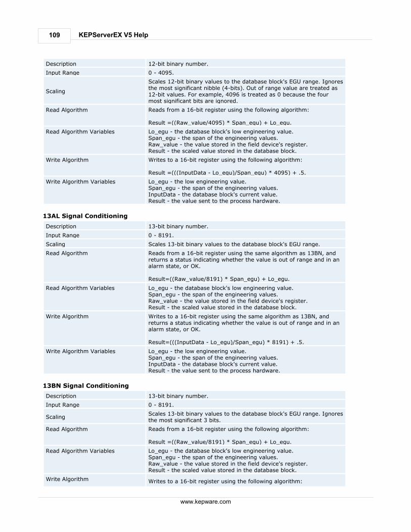
109
www.kepware.com
KEPServerEX V5 Help
Description 12-bit binary number.
Input Range 0 - 4095.
Scaling
Scales 12-bit binary values to the database block's EGU range. Ignoresthe most significant nibble (4-bits). Out of range value are treated as12-bit values. For example, 4096 is treated as 0 because the fourmost significant bits are ignored.
Read Algorithm Reads from a 16-bit register using the following algorithm:
Result =((Raw_value/4095) * Span_egu) + Lo_egu.
Read Algorithm Variables Lo_egu - the database block's low engineering value.Span_egu - the span of the engineering values.Raw_value - the value stored in the field device's register.Result - the scaled value stored in the database block.
Write Algorithm Writes to a 16-bit register using the following algorithm:
Result =(((InputData - Lo_egu)/Span_egu) * 4095) + .5.
Write Algorithm Variables Lo_egu - the low engineering value.Span_egu - the span of the engineering values.InputData - the database block's current value.Result - the value sent to the process hardware.
13AL Signal Conditioning
Description 13-bit binary number.
Input Range 0 - 8191.
Scaling Scales 13-bit binary values to the database block's EGU range.
Read Algorithm Reads from a 16-bit register using the same algorithm as 13BN, andreturns a status indicating whether the value is out of range and in analarm state, or OK.
Result=((Raw_value/8191) * Span_egu) + Lo_egu.
Read Algorithm Variables Lo_egu - the database block's low engineering value.Span_egu - the span of the engineering values.Raw_value - the value stored in the field device's register.Result - the scaled value stored in the database block.
Write Algorithm Writes to a 16-bit register using the same algorithm as 13BN, andreturns a status indicating whether the value is out of range and in analarm state, or OK.
Result=(((InputData - Lo_egu)/Span_egu) * 8191) + .5.
Write Algorithm Variables Lo_egu - the low engineering value.Span_egu - the span of the engineering values.InputData - the database block's current value.Result - the value sent to the process hardware.
13BN Signal Conditioning
Description 13-bit binary number.
Input Range 0 - 8191.
ScalingScales 13-bit binary values to the database block's EGU range. Ignoresthe most significant 3 bits.
Read Algorithm Reads from a 16-bit register using the following algorithm:
Result =((Raw_value/8191) * Span_egu) + Lo_egu.
Read Algorithm Variables Lo_egu - the database block's low engineering value.Span_egu - the span of the engineering values.Raw_value - the value stored in the field device's register.Result - the scaled value stored in the database block.
Write Algorithm Writes to a 16-bit register using the following algorithm:

110
www.kepware.com
KEPServerEX V5 Help
Result =(((InputData - Lo_egu)/Span_egu) * 8191) + .5.
Write Algorithm Variables Lo_egu - the low engineering value.Span_egu - the span of the engineering values.InputData - the database block's current value.Result - the value sent to the process hardware.
14AL Signal Conditioning
Description 14-bit binary number.
Input Range 0 - 16383.
Scaling Scales 14-bit binary values to the database block's EGU range.
Read Algorithm Reads from a 16-bit register using the same algorithm as 14BN, andreturns a status indicating whether the value is out of range and in analarm state, or OK.
Result=((Raw_value/16383) * Span_egu) + Lo_egu.
Read Algorithm Variables Lo_egu - the database block's low engineering value.Span_egu - the span of the engineering values.Raw_value - the value stored in the field device's register.Result - the scaled value stored in the database block.
Write Algorithm Writes to a 16-bit register using the same algorithm as 14BN, andreturns a status indicating whether the value is out of range and in analarm state, or OK.
Result=(((InputData - Lo_egu)/Span_egu) * 16383) + .5.
Write Algorithm Variables Lo_egu - the low engineering value.Span_egu - the span of the engineering values.InputData - the database block's current value.Result - the value sent to the process hardware.
14BN Signal Conditioning
Description 14-bit binary number.
Input Range 0 - 16383.
ScalingScales 14-bit binary values to the database block's EGU range. Ignoresthe most significant 2 bits.
Read Algorithm Reads from a 16-bit register using the following algorithm:
Result=((Raw_value/16383) * Span_egu) + Lo_egu.
Read Algorithm Variables Lo_egu - the database block's low engineering value.Span_egu - the span of the engineering values.Raw_value - the value stored in the field device's register.Result - the scaled value stored in the database block.
Write Algorithm Writes to a 16-bit register using the following algorithm:
Result=(((InputData - Lo_egu)/Span_egu) * 16383) + .5.
Write Algorithm Variables Lo_egu - the low engineering value.Span_egu - the span of the engineering values.InputData - the database block's current value.Result - the value sent to the process hardware.
15AL Signal Conditioning
Description 15-bit binary number.
Input Range 0 - 32767.
Scaling Scales 15-bit binary values to the database block's EGU range.
Read Algorithm Reads from a 16-bit register with alarming using the same algorithmas 15BN, and returns a status indicating whether the value is out ofrange and in an alarm state, or OK.

111
www.kepware.com
KEPServerEX V5 Help
Result=((Raw_value/32767) * Span_egu) + Lo_egu.
Read Algorithm Variables Lo_egu - the database block's low engineering value.Span_egu - the span of the engineering values.Raw_value - the value stored in the field device's register.Result - the scaled value stored in the database block.
Write Algorithm Writes to a 16-bit register with alarming using the same algorithm as15BN, and returns a status indicating whether the value is out of rangeand in an alarm state, or OK.
Result=(((InputData - Lo_egu)/Span_egu) * 32767) + .5.
Write Algorithm Variables Lo_egu - the low engineering value.Span_egu - the span of the engineering values.InputData - the database block's current value.Result - the value sent to the process hardware.
15BN Signal Conditioning
Description 15-bit binary number.
Input Range 0 - 32767.
ScalingScales 15-bit binary values to the database block's EGU range. Ignoresthe most significant bit.
Read Algorithm Reads from a 16-bit register using the following algorithm:
Result =((Raw_value/32767) * Span_egu) + Lo_egu.
Read Algorithm Variables Lo_egu - the database block's low engineering value.Span_egu - the span of the engineering values.Raw_value - the value stored in the field device's register.Result - the scaled value stored in the database block.
Write Algorithm Writes to a 16-bit register using the following algorithm:
Result =(((InputData - Lo_egu)/Span_egu) * 32767) + .5.
Write Algorithm Variables Lo_egu - the low engineering value.Span_egu - the span of the engineering values.InputData - the database block's current value.Result - the value sent to the process hardware.
20P Signal Conditioning
Description 6400 – 32000 Clamp.
Input Range 6400 – 32000.
Scaling Scales binary values to the database block's EGU range. Clamps valueto 6400 – 32000 range.
Read Algorithm Reads from a 16-bit register using the following algorithm:
Result =(((Raw_value - 6400)/25600) * Span_egu) + Lo_egu.
Read Algorithm Variables Lo_egu - the database block's low engineering value.Span_egu - the span of the engineering values.Raw_value - the value stored in the field device's register.Result - the scaled value stored in the database block.
Write Algorithm Writes to a 16-bit register using the following algorithm:
Result =(((InputData - Lo_egu)/Span_egu) * 25600) + 6400.5.
Write Algorithm Variables Lo_egu - the low engineering value.Span_egu - the span of the engineering values.InputData - the database block's current value.Result - the value sent to the process hardware.
TNON Signal Conditioning
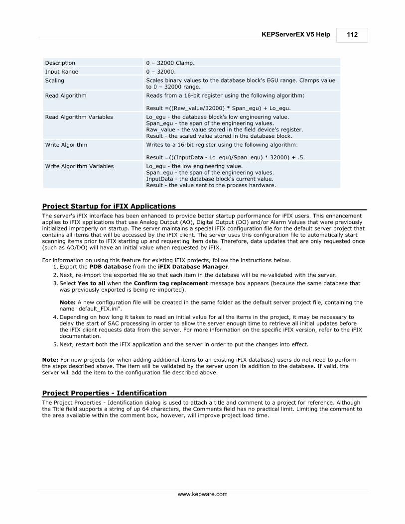
112
www.kepware.com
KEPServerEX V5 Help
Description 0 – 32000 Clamp.
Input Range 0 – 32000.
Scaling Scales binary values to the database block's EGU range. Clamps valueto 0 – 32000 range.
Read Algorithm Reads from a 16-bit register using the following algorithm:
Result =((Raw_value/32000) * Span_egu) + Lo_egu.
Read Algorithm Variables Lo_egu - the database block's low engineering value.Span_egu - the span of the engineering values.Raw_value - the value stored in the field device's register.Result - the scaled value stored in the database block.
Write Algorithm Writes to a 16-bit register using the following algorithm:
Result =(((InputData - Lo_egu)/Span_egu) * 32000) + .5.
Write Algorithm Variables Lo_egu - the low engineering value.Span_egu - the span of the engineering values.InputData - the database block's current value.Result - the value sent to the process hardware.
Project Startup for iFIX Applications
The server's iFIX interface has been enhanced to provide better startup performance for iFIX users. This enhancementapplies to iFIX applications that use Analog Output (AO), Digital Output (DO) and/or Alarm Values that were previouslyinitialized improperly on startup. The server maintains a special iFIX configuration file for the default server project thatcontains all items that will be accessed by the iFIX client. The server uses this configuration file to automatically startscanning items prior to iFIX starting up and requesting item data. Therefore, data updates that are only requested once(such as AO/DO) will have an initial value when requested by iFIX. For information on using this feature for existing iFIX projects, follow the instructions below.
1. Export the PDB database from the iFIX Database Manager.
2. Next, re-import the exported file so that each item in the database will be re-validated with the server.
3. Select Yes to all when the Confirm tag replacement message box appears (because the same database thatwas previously exported is being re-imported).
Note: A new configuration file will be created in the same folder as the default server project file, containing thename "default_FIX.ini".
4. Depending on how long it takes to read an initial value for all the items in the project, it may be necessary todelay the start of SAC processing in order to allow the server enough time to retrieve all initial updates beforethe iFIX client requests data from the server. For more information on the specific iFIX version, refer to the iFIXdocumentation.
5. Next, restart both the iFIX application and the server in order to put the changes into effect.
Note: For new projects (or when adding additional items to an existing iFIX database) users do not need to performthe steps described above. The item will be validated by the server upon its addition to the database. If valid, theserver will add the item to the configuration file described above.
Project Properties - Identification
The Project Properties - Identification dialog is used to attach a title and comment to a project for reference. Althoughthe Title field supports a string of up 64 characters, the Comments field has no practical limit. Limiting the comment tothe area available within the comment box, however, will improve project load time.

113
www.kepware.com
KEPServerEX V5 Help
Project Properties - OPC DA Settings
This server supports the OPC Foundation's Data Access Specifications for 1.0, 2.0 and 3.0 simultaneously. While thisprovides the utmost level of compatibility, there may be times when forcing the server to use one method over anotheris necessary. The OPC DA Options dialog is used to make these selections.

114
www.kepware.com
KEPServerEX V5 Help
Descriptions of the parameters are as follows.
When enabled, Enable OPC 1.0 allows the server to accept OPC client connections from OPC clients that support
the 1.0 specification. The 1.0 operation is enabled by default.
When enabled, Enable OPC 2.0 allows the server to accept OPC client connections from OPC clients that support
the 2.0 specification. The 2.0 operation is enabled by default.
When enabled, Enable OPC 3.0 allows the server to accept OPC client connections from OPC clients that support
the 3.0 specification. The 3.0 operation is enabled by default.
When enabled, Include Hints allows OPC client applications to browse the address formatting Hints available for
each communications driver. The Hints provide a visual quick reference on how a particular device's data can beaddressed. This can be useful when entering Dynamic Tags from the OPC client. The hint items are not valid OPCtags. Some OPC client applications may try to add the Hint tags to their tag database. When this occurs, theclient will receive an error from the server. This is not a problem for most clients, although it can cause others tostop adding tags automatically or report errors. Users can prevent this from occurring by turning the Hints On orOff. This option is disabled by default.
When enabled, Include Tag Properties allows OPC client applications to browse the tag properties available for
each tag in the address space. This setting is disabled by default.
Shut down wait timeout allows users to configure how long the server will wait for an OPC client to return
from the server shut down event. If the client application does not return within the timeout period, the serverwill complete its shutdown and exit. The valid range is 10 to 60 seconds. The default is 15 seconds.
Wait for synchronous request parameter allows users to configure how long the server will wait for a
synchronous Read or Write operation to complete. If a synchronous operation is in progress and the timeout isexceeded, the server will force the operation to complete with a failure to the OPC client. This prevents OPCclients from appearing to become locked up when using synchronous operations. The valid range is 5 to 60seconds. The default is 15 seconds.
Project Properties - OPC DA Compliance
The server has been designed to provide the highest level of compatibility with the OPC Foundation's specifications. Intesting however it has been found that being fully compatible with the specification and working with all OPC clientapplications is a different matter. The OPC DA Compliance option allows users to tailor the operation of the server to

115
www.kepware.com
KEPServerEX V5 Help
better meet the needs of rare OPC clients. Normally these options will not need to be adjusted for a majority of the OPCclient applications users will encounter. The OPC compliancy dialog appears as shown below.
Descriptions of the parameters are as follows.
Perform the following operations is the master enabling switch for the options present in the list box. When
enabled, the server will set all options to conform to OPC compliancy. This setting is not enabled by default.
When enabled, Reject unsupported Language IDs only allows Language IDs that are natively supported by
the server. If the OPC client application attempts to add an OPC group to the server and receives a generalfailure, it is possible the client has given the server a Language ID that is not natively supported. If this occurs,the server will reject the group addition. To resolve this particular issue, disable the compliant feature to forcethe server to accept any Language ID.
When enabled, Ignore dead-band when returning data for cache needs allows the server to ignore the
dead-band setting on OPC groups added to the server. For some OPC clients, passing the correct value for dead-band causes problems that may result in the OPC client (such as, having good data even though it does notappear to be updating frequently or at all). This condition is rare. As such, the selection should normally be left inits default disabled state.
When enabled, Return all browse items regardless of read-write filter causes the server to return all tags
to an OPC client application when a browse request is made, regardless of the access filter applied to the OPCclients tag browser.
When enabled, Data type support for 2.05a causes the server to adhere to the data type requirements and
expected behaviors for data type coercion that were added to the 2.05a specification.
When enabled, Return synchronous device read failure if one or more items would result in bad quality
causes the server to return a failure if one or more items for a synchronous device Read results in a bad qualityread. Compliance requires the server to return success, indicating that the server could complete the requesteven though the data for one or more items may include a bad and/or uncertain quality.
When enabled, Return initial updates for items in a single callback causes the server to return all
outstanding initial item updates in a single callback. When not selected, the server returns initial updates as theyare available (which could result in multiple callbacks).
When enabled, Respect Language ID set by client when performing data type conversions determines
whether the server uses the Locale ID of the running Windows Operating System or the Locale ID set by the OPCclient when performing data type conversions. For example, a string representing a floating point number such as

116
www.kepware.com
KEPServerEX V5 Help
1,200 would be converted to One Thousand - Twelve Hundred if converted using English metrics, but would beOne and Two-Tenths if converted using German metrics. Thus, if German software is running on an English OS,users need to determine how the comma will be handled. This setting allows for such flexibility. By default, anddue to historical implementation, the server respects the Locale ID of the operating system.
Project Properties - DDE
While the server is first and foremost an OPC server, there are still a number of applications that require DynamicData Exchange (DDE) to share data. The server provides access to DDE applications that support one of the followingDDE formats: CF_Text, XL_Table and Advanced DDE. CF_Text and XL_Table are standard DDE formats developedby Microsoft for use with all DDE aware applications. Advanced DDE is a high performance format supported by anumber of client applications specific to the industrial market. Important: In order for the DDE interface to connect with the server, the Runtime must be allowed to interact with thedesktop. For more information, refer to How To... Allow Desktop Interactions.
DDE Option Dialog
The DDE Option dialog, which allows users to determine how the server provides DDE data, can be reached by clicking File | Project Properties | DDE in the server. Its parameters can be used to tailor the DDE operation to fit theapplication's needs.
Enable DDE Connections to the Server
This parameter determines whether the DDE server portion of the server will be enabled or disabled. If DDE operationis disabled, the server will not respond to any request for DDE data. If intending to use the server only as an OPCserver, users may want to disable DDE operation. Doing so can increase the data's security and improve the server'soverall performance. DDE is disabled by default. See Also: How To... Use DDE with the Server.
Enable Net DDE
This parameter determines whether Microsoft's Net DDE services will be enabled or disabled. If intending to use theserver only with local DDE client applications, users should keep Net DDE disabled (the default setting). Starting the NetDDE services can be a time consuming process that can slow the startup of the server. If users do need to use Net

117
www.kepware.com
KEPServerEX V5 Help
DDE, enabling it will cause the server to automatically register its share names and start the Net DDE service manager.DDE shares will be removed when the server shuts down. See Also: How To... Use Net DDE.
Service Name
This parameter allows users to change how the server appears as an application name to DDE clients. This name willinitially be set to allow compatibility with the previous versions of the server. If users need to replace an existing DDEserver however, the server's service name can be changed to match the DDE server being replaced. The service nameallows a string of 1 to 32 characters to be entered.
Formats
This parameter allows users to configure the format of DDE to provide to client applications. All three formats areenabled by default. This is particularly useful when users experience problems connecting a DDE client application tothe server: each of the DDE formats can be disabled in order to isolate a specific format for testing purposes. Note: Every DDE aware application must support CF_Text at a minimum.
Update active clients
This interval setting is used to batch up DDE data so that it can be transferred to client applications. When using a DDEformat performance gains only come when large blocks of server data can be sent in a single DDE response. Toimprove the ability of the server to gather a large block of data, the update timer can be set to allow a pool of new datato accumulate before a being sent to a client application. The valid range of the update timer is 20-60000 milliseconds.The default is 100 milliseconds.
Wait
This parameter is used to configure a timeout for the completion of DDE request. If a DDE client request (either a Reador Write operation) on the server cannot be completed within the specified timeout, an error will be returned to the DDEClient. The valid range is 1-30 seconds. The default is 15 seconds. Note: Server Runtime may have to be reinitialized for changes to take effect.
Project Properties - FastDDE/Suitelink
The server's support of Wonderware Corporation's FastDDE and SuiteLink simplifies the task of connecting the serverwith FactorySuite applications. The Wonderware connectivity toolkit is used to simultaneously provide OPC andFastDDE/SuiteLink connectivity while allowing for quick access to device data without the use of intermediary bridgingsoftware. Important: In order for the FastDDE interface to connect with the server, the Runtime must be allowed to interact withthe desktop. For more information, refer to How To... Allow Desktop Interactions.
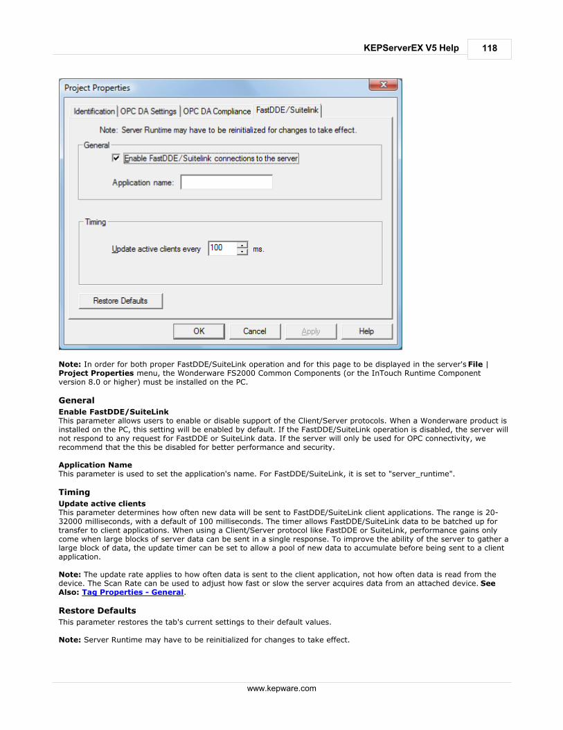
118
www.kepware.com
KEPServerEX V5 Help
Note: In order for both proper FastDDE/SuiteLink operation and for this page to be displayed in the server's File |Project Properties menu, the Wonderware FS2000 Common Components (or the InTouch Runtime Componentversion 8.0 or higher) must be installed on the PC.
General
Enable FastDDE/SuiteLinkThis parameter allows users to enable or disable support of the Client/Server protocols. When a Wonderware product isinstalled on the PC, this setting will be enabled by default. If the FastDDE/SuiteLink operation is disabled, the server willnot respond to any request for FastDDE or SuiteLink data. If the server will only be used for OPC connectivity, werecommend that the this be disabled for better performance and security. Application NameThis parameter is used to set the application's name. For FastDDE/SuiteLink, it is set to "server_runtime".
Timing
Update active clientsThis parameter determines how often new data will be sent to FastDDE/SuiteLink client applications. The range is 20-32000 milliseconds, with a default of 100 milliseconds. The timer allows FastDDE/SuiteLink data to be batched up fortransfer to client applications. When using a Client/Server protocol like FastDDE or SuiteLink, performance gains onlycome when large blocks of server data can be sent in a single response. To improve the ability of the server to gather alarge block of data, the update timer can be set to allow a pool of new data to accumulate before being sent to a clientapplication.
Note: The update rate applies to how often data is sent to the client application, not how often data is read from thedevice. The Scan Rate can be used to adjust how fast or slow the server acquires data from an attached device. SeeAlso: Tag Properties - General.
Restore Defaults
This parameter restores the tab's current settings to their default values. Note: Server Runtime may have to be reinitialized for changes to take effect.

119
www.kepware.com
KEPServerEX V5 Help
Project Properties - iFIX PDB Settings
The iFIX PDB Settings dialog contains parameters that allow users to adjust the behavior between the processing of theiFIX process database (PDB) tags and the server tags. To access this tab, click File | Project Properties. Note: The iFIX PDB Settings dialog will only be displayed in Project Properties if iFIX is installed on the computer. Important: In some cases, the Process Mode parameter must be set to System Service in order for the iFix PDBinterface to work with the Runtime. For more information, refer to Process Modes.
Note: It is recommended that users keep the default values for each field. Users should also ensure that the settingsmeet the application's requirements.
General
Enable connectivity to iFix PDB.This parameter is used to enable or disable support of the Client/Server protocols. If the iFix PDB operation is disabled,the server will not respond to any request for iFix PDB data. For better performance and security when the server isonly being used for OPC connectivity, disable this parameter. Wait xx seconds before timing out on requests between PDB and DriverThis parameter specifies the amount of time that the iFIX PDB will wait for a response from an add, remove, Read orWrite request before timing out. Once timed out, the request will be discarded on behalf of the server. A timeout canoccur if the server is busy processing other requests or if the server has lost communications with iFIX PDB. In the caseof lost communications, the iFIX PDB will automatically re-establish communications with the server so that successivetimeouts do not occur. The valid range is 5-60 seconds. The default setting is 5 seconds. Enable Latched DataNormally, the iFIX application's data links will display a series of question marks (such as "????") if a communicationfailure has occurred. Users, however, may want to have a value displayed at all times. By enabling latched data, thelast value successfully read will be preserved on the screen. This feature is disabled by default. Note: Data latching is not supported for AR and DR blocks.

120
www.kepware.com
KEPServerEX V5 Help
iFIX PDB Read Inactivity
This parameter allows the server to automatically deactivate tags that have not been read by iFIX for the time periodspecified. This reduces unnecessary polling of the process hardware. When iFIX PDB Read Inactivity feature is enabled,the server will look through its list of tags every 15 seconds and will deactivate any that are idle. If iFIX has notperformed a Read request of a tag for the time period specified, the tag is considered idle. Since the server checks foridle tags on a 15 second cycle, a tag may not get set inactive at precisely this time from its last Read; it could be up to15 seconds longer depending on when the last read occurred in the check cycle. If iFIX requests data from a tag thathas been previously deactivated, the server will reactivate the tag and resume polling the hardware. This feature is disabled by default upon driver install. Once this feature is enabled, however, it becomes applied to allprojects. Users may specify an idle time of up to 6:23:59:59 (1 week). Caution: This feature is meant to be used with Register Tags only and can cause non-register tags to go off scan. Toavoid this situation when using this feature, be sure to set the inactivity timer greater than the longest scan timeconfigured in the iFIX database.
Format Range Default Value
[days:hours:minutes:seconds] 0:00:00:15 to 6:23:59:59 0:00:00:15 (15 seconds)
Note: The time period can also be specified in seconds. For example, if 62 is entered, the page will show 0:00:01:02when accessed next. Examples
Time Format
20 seconds 0:00:00:20 or 20
1 minute 0:00:01:00 or 60
1 hour and 30 minutes 0:01:30:00 or 5400
2 days 2:00:00:00
Restore Defaults
This parameter restores the tab's current settings to their default values.
Project Properties - OPC UA
OPC Unified Architecture (UA) provides a platform independent interoperability standard. It is not a replacement forOPC Data Access (DA) technologies: for most industrial applications, UA will complement or enhance an existing DAarchitecture. The OPC UA tab displays the current OPC UA settings in the server. Note: To change a setting, click in the specific parameter's second column. This will invoke a drop-down menu thatdisplays the options available.

121
www.kepware.com
KEPServerEX V5 Help
Server Interface
Descriptions of the parameters are as follows: Enable: When enabled, the UA server interface will be initialized and accept client connections. When disabled,
the remaining parameters on this page will also be disabled.
Log Diagnostics: When enabled, OPC UA stack diagnostics will be logged to the Event Log. This should only be
enabled for debugging purposes.
Client Sessions
Descriptions of the parameters are as follows:1. Allow Anonymous Login: When disabled, this parameter specifies that user name and password information
will be required to establish a connection. The default setting is enabled.
2. Max Connections: This parameter specifies the maximum number of supported connections. The valid range is1 to 100. The default setting is 100.
3. Session Timeouts: This parameter specifies the UA client's timeout limit for establishing a session. Values maybe changed depending on the needs of the application. The default values are 15 to 60.
o Minimum: This parameter specifies the UA client's minimum timeout limit. The default setting is 15.
o Maximum: This parameter specifies the UA client's maximum timeout limit. The default setting is 60.
Browsing
Descriptions of the parameters are as follows:1. Return Tag Properties: When enabled, this parameter allows UA client applications to browse the tag
properties available for each tag in the address space. This setting is disabled by default.
2. Return Address Hints: When enabled, this parameter allows UA client applications to browse the addressformatting hints available for each item. Although the hints are not valid UA tags, certain UA client applicationsmay try to add them to the tag database. When this occurs, the client will receive an error from the server. This
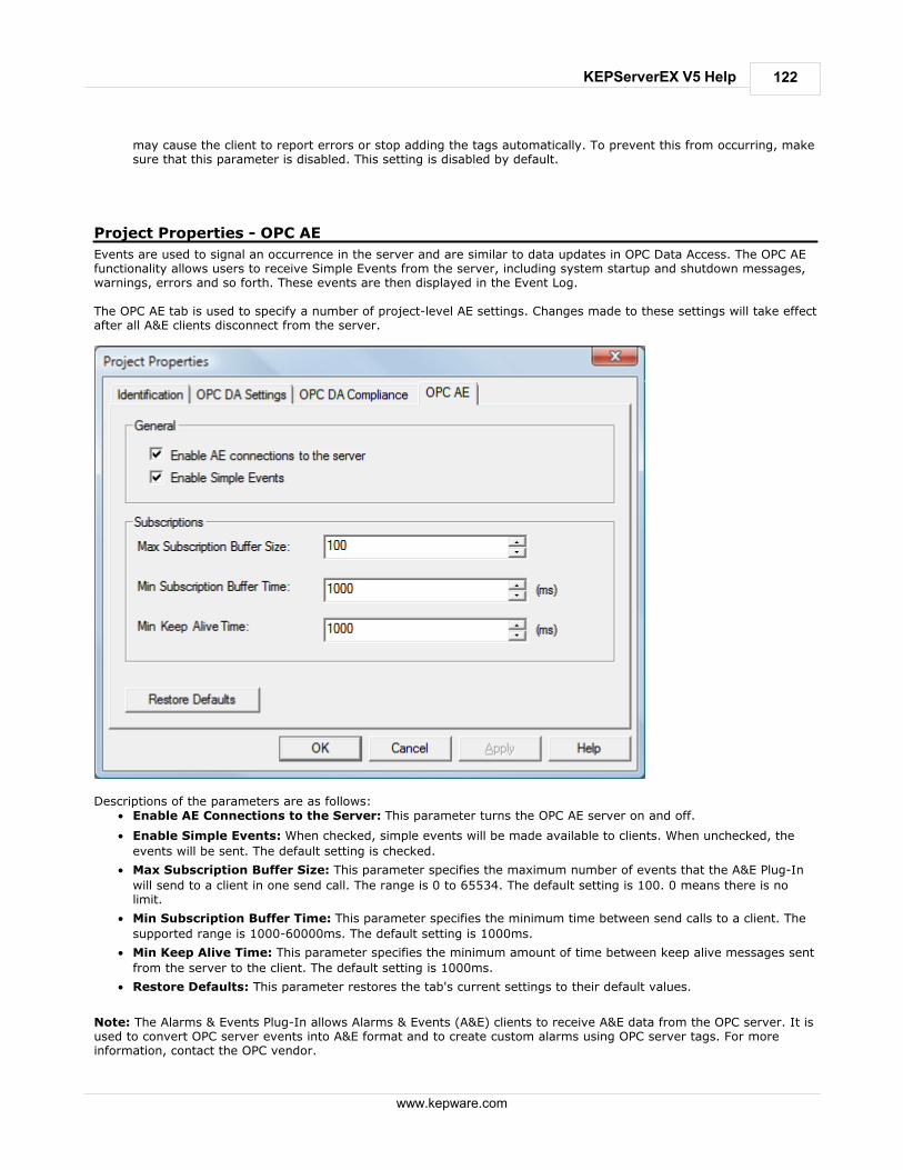
122
www.kepware.com
KEPServerEX V5 Help
may cause the client to report errors or stop adding the tags automatically. To prevent this from occurring, makesure that this parameter is disabled. This setting is disabled by default.
Project Properties - OPC AE
Events are used to signal an occurrence in the server and are similar to data updates in OPC Data Access. The OPC AEfunctionality allows users to receive Simple Events from the server, including system startup and shutdown messages,warnings, errors and so forth. These events are then displayed in the Event Log. The OPC AE tab is used to specify a number of project-level AE settings. Changes made to these settings will take effectafter all A&E clients disconnect from the server.
Descriptions of the parameters are as follows:
Enable AE Connections to the Server: This parameter turns the OPC AE server on and off.
Enable Simple Events: When checked, simple events will be made available to clients. When unchecked, the
events will be sent. The default setting is checked.
Max Subscription Buffer Size: This parameter specifies the maximum number of events that the A&E Plug-In
will send to a client in one send call. The range is 0 to 65534. The default setting is 100. 0 means there is nolimit.
Min Subscription Buffer Time: This parameter specifies the minimum time between send calls to a client. The
supported range is 1000-60000ms. The default setting is 1000ms.
Min Keep Alive Time: This parameter specifies the minimum amount of time between keep alive messages sent
from the server to the client. The default setting is 1000ms.
Restore Defaults: This parameter restores the tab's current settings to their default values.
Note: The Alarms & Events Plug-In allows Alarms & Events (A&E) clients to receive A&E data from the OPC server. It isused to convert OPC server events into A&E format and to create custom alarms using OPC server tags. For moreinformation, contact the OPC vendor.
123
www.kepware.com
KEPServerEX V5 Help
How Do I...
For descriptive information on how to complete the follow actions, select a link from the list below. Use DDE with the Server
Use Net DDE Across a Network
Use Dynamic Tag Addressing
Process Array Data
Create and Use an Alias
Use an Alias to Optimize a Project
Optimize the Server Project
Select the Correct Network Cable
Use Ethernet Encapsulation
Resolve Comm Issues When the DNS/DHCP Device Connected to the Server is Power Cycled
Allow Desktop Interactions
How To... Use DDE with the Server
Using DDE in Your Application
Dynamic Data Exchange (DDE) is a Microsoft communications protocol that provides a method for exchanging databetween applications running on a Windows operating system. The DDE client program opens a channel to the DDEserver application and requests item data using a hierarchy of the Application (Service) name, Topic name andItem name.
Example 1: Accessing a Register Locally (Using the Default Topic)
Syntax: <application>|<topic>!<item> Example: MyDDE|_ddedata!Modbus.PLC1.40001 Where: application: DDE service name topic: _ddedata (Default topic for all DDE data not using an Alias Map entry) item: Modbus.PLC1.40001
Example 2: Accessing a Register Locally (Using an Alias Name as a Topic)
Syntax: <application>|<topic>!<item> Example: MyDDE|ModPLC1!40001 Where: application: DDE service name topic: ModPLC1 (Topic now using Alias Map entry) item: 40001
See Also:
Project Properties - DDE
FastDDE & SuiteLink
What is the Alias Map?
Note 1: For possible additional syntax, refer to the DDE client's specific help documentation. Note 2: For information on how to connect to remote applications using DDE, refer to Using Net DDE Across aNetwork.
How To... Use Net DDE Across a Network
DDE provides a way to share data between Windows applications as long as they exist on the same machine. Net DDEshares data from a DDE server located on a local PC with DDE client applications located on remote PCs. Moreinformation on how to configure a PC to support Net DDE is available online.
124
www.kepware.com
KEPServerEX V5 Help
How To... Use Dynamic Tag Addressing
This server can also be used to dynamically reference a physical device data address from the server. The server willdynamically create a tag for requested item. Users cannot browse for tags from one client that were dynamically addedby another. Before adding tags dynamically, users should note the following.
The correct syntax must be used for the data address. For more information on the specific driver's syntax, refer
to its help documentation.
If users do not specify the requested item's data type, it will be set to the default setting by the application. For
more information on the specific driver's supported data types, refer to its help documentation. The default datatype will be displayed in bold letters.
Note: In this example, the Simulator driver is to explain addressing. Assume that the channel name is 'Channel1' andthe device name is 'Device1'.
In a Non-OPC Client
In order to get data from register 'K0001' in the simulated device, use an Item ID of 'Channel1.Device1.K001.' Thedefault data type for this register is 'Short.' Since non OPC Clients do not provide an update rate to the server, theDynamic Tag's default update rate will be 100 msec. Both data type and update rate can be overridden after thedynamic request is sent. To override the tag defaults, use the commercial AT sign (@) at the end of the item. If intending to add the register asa DWord (unsigned 32 bit) data type, simply use an Item ID of 'Channel1.Device1.K0001@DWord.' To change thedefault update rate to 1000msec , use 'Channel1.Device1.K0001@1000.' To change both defaults, use 'Channel1.Device1.K0001@DWord,1000.' Note: The client application must be able to accept special characters like the '@' in its address space.
In an OPC Client
In an OPC client, the same syntax can be used to override the data type if the client application does not provide ameans of specifying a data type when adding the OPC Item. Since the item's update rate is not used in OPC, there is noneed to override it. Note: The client application must be able to accept special characters like the '@' in its address space.
How To... Process Array Data
Many of the drivers available for this server allow clients to access data in an array format. Arrays allow the clientapplication to request a specific set of contiguous data in one request. Arrays are one specific data type; thus, userswould not have an array with a combination of Word and DWord data types. Furthermore, arrays are written to in onetransaction. To use arrays in the server, the client application must support the ability to at least read array data.
In a DDE Client
Array data is only available to the client when using CF_TEXT or Advanced DDE clipboard formats. For client applications using Advanced DDE, the number of elements in the array is specified in thesPACKDDE_DATAHDR_TAG structure. Only single dimensional arrays are supported by this protocol. This structureshould be used when poking array data to the server. For clients using CF_TEXT, one or two-dimensional arrays are supported. Data in each row is separated by a TAB(0x09) character and each row is terminated with a CR (0x0d) and a LF (0x0a) character. When a client wants to pokean array of data values, the text string written should have this delimiter format. When poking to an array tag in either format, the entire array does not need to be written, but the starting location isfixed. If attempting to poke data in an array format to a tag that was not declared as an array, only the first value inthe array will be written. If attempting to poke more data than the tag's array size, only as much data as the tag'sarray size will be written. If attempting to poke data while leaving some data values blank, the server will use the lastknown value for that array element when writing back to the device. If the value in that register has been changed buthas not been updated in the server, it will be overwritten with the old value. For this reason, it is best to be cautiouswhen writing data to arrays.
In an OPC Client
In OPC Clients that support arrays, the OPC Item data value is actually a variant array data type. The OPC Client parsesthe array element data: some clients will create sub tags for display purposes. For example, if the OPC client created a

125
www.kepware.com
KEPServerEX V5 Help
tag in its database named 'Process,' and the associated OPC item was a single dimensional array of 5 elements, it mightcreate 5 tags named 'Process_1', 'Process2' and etc. Other clients (such as the OPC Quick Client) may display the dataas CSV (Comma Separated Values).
How To... Create and Use an Alias
Complex Tag Reference Example
The image below displays a Complex Tag reference in the server.
For example, to create a DDE link to an application for the "ToolDepth" tag, the DDE link must be entered as "<DDEservice name>|_ddedata!Channel1.Device1.Machine1.Cell2.ToolDepth". Although the DDE link's simple <application>|<topic>!<item> format still exists, the content becomes more complexwhen optional tag groups and the channel name are required as part of the topic. The Alias Map allows a shorterversion of the reference to be used in DDE client applications. For more information, refer to What is the Alias Map.
Creating Aliases for Complex Address Paths
For information on creating aliases to simplify Complex Tags' address paths, follow the instructions below.1. In the server, click Edit | Alias Map.
2. Click the New Alias icon, which appears as .

126
www.kepware.com
KEPServerEX V5 Help
3. Next, browse to the group or device that contains the item that will be referenced.
4. Enter an alias name that will represent the complex tag reference. This alias name can now be used in the clientapplication to address the tag found in the server.
5. The complex topic and item name "_ddedata!Channel1.Device1.Machine1.Cell2" can be replaced by using thealias "Mac1Cell2". When applied to the example above, the DDE link in the application can be entered as "<DDEservice name>|Mac1Cell2!ToolDepth".
Note 1: If Net DDE is enabled, the Alias Map entries will be registered as DDE shares for use by remote applications.The names given to each Alias Map entry must not conflict with any existing DDE shares already defined on the serverPC. For more information, refer to How to Use Net DDE Across a Network. Note 2: Although possible, it is not recommended that users create an alias that shares a name with a channel. Theclient's item will fail if it references a dynamic address using the shared name. For example, if an alias is named
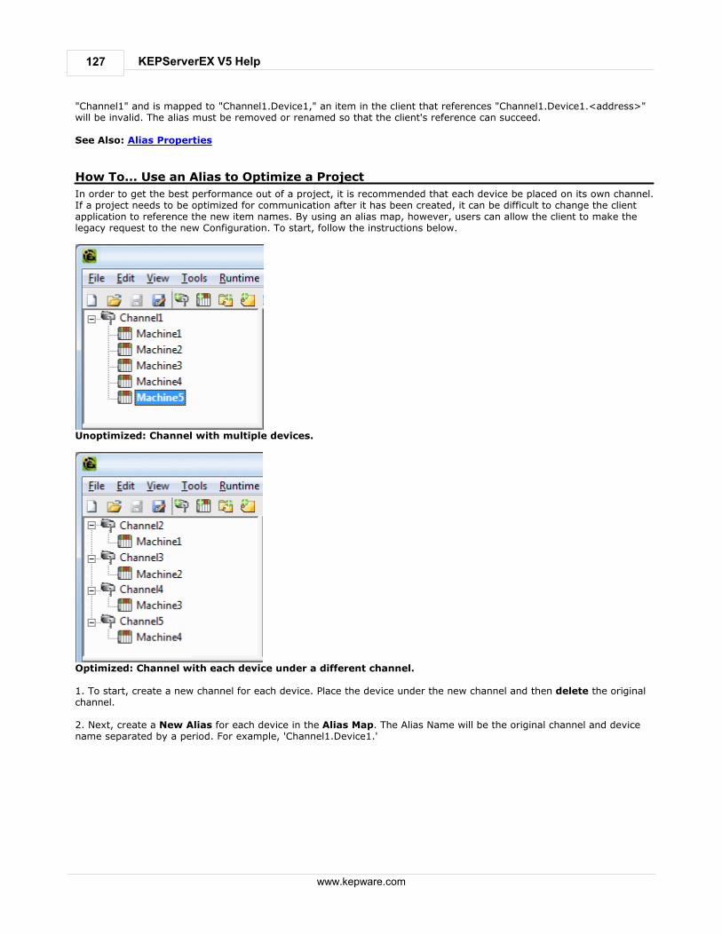
127
www.kepware.com
KEPServerEX V5 Help
"Channel1" and is mapped to "Channel1.Device1," an item in the client that references "Channel1.Device1.<address>"will be invalid. The alias must be removed or renamed so that the client's reference can succeed. See Also: Alias Properties
How To... Use an Alias to Optimize a Project
In order to get the best performance out of a project, it is recommended that each device be placed on its own channel.If a project needs to be optimized for communication after it has been created, it can be difficult to change the clientapplication to reference the new item names. By using an alias map, however, users can allow the client to make thelegacy request to the new Configuration. To start, follow the instructions below.
Unoptimized: Channel with multiple devices.
Optimized: Channel with each device under a different channel. 1. To start, create a new channel for each device. Place the device under the new channel and then delete the originalchannel. 2. Next, create a New Alias for each device in the Alias Map. The Alias Name will be the original channel and devicename separated by a period. For example, 'Channel1.Device1.'
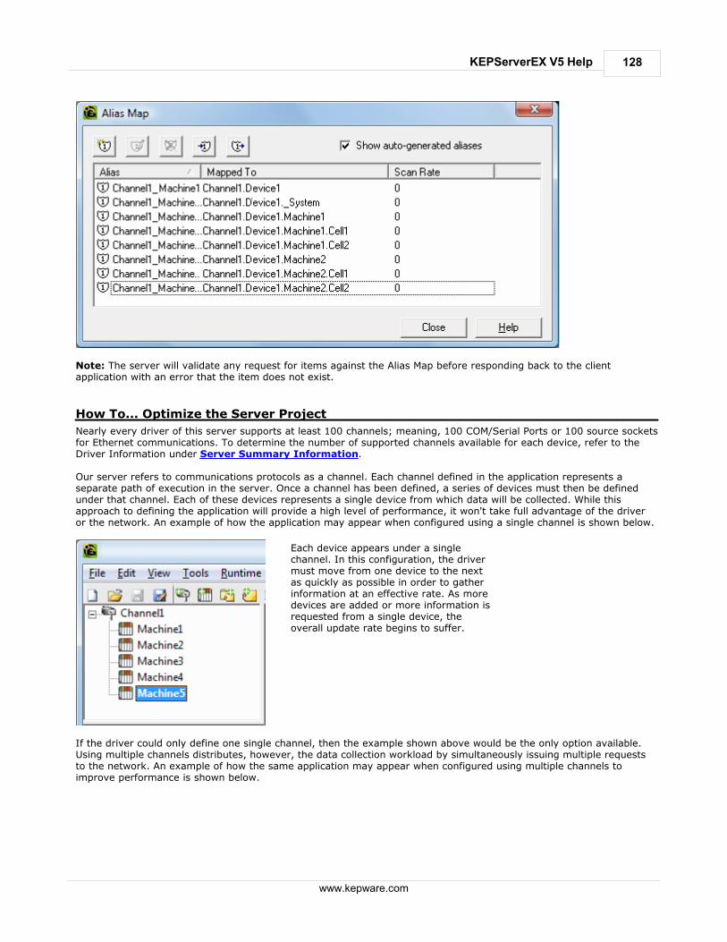
128
www.kepware.com
KEPServerEX V5 Help
Note: The server will validate any request for items against the Alias Map before responding back to the clientapplication with an error that the item does not exist.
How To... Optimize the Server Project
Nearly every driver of this server supports at least 100 channels; meaning, 100 COM/Serial Ports or 100 source socketsfor Ethernet communications. To determine the number of supported channels available for each device, refer to theDriver Information under Server Summary Information. Our server refers to communications protocols as a channel. Each channel defined in the application represents aseparate path of execution in the server. Once a channel has been defined, a series of devices must then be definedunder that channel. Each of these devices represents a single device from which data will be collected. While thisapproach to defining the application will provide a high level of performance, it won't take full advantage of the driveror the network. An example of how the application may appear when configured using a single channel is shown below.
Each device appears under a singlechannel. In this configuration, the drivermust move from one device to the nextas quickly as possible in order to gatherinformation at an effective rate. As moredevices are added or more information isrequested from a single device, theoverall update rate begins to suffer.
If the driver could only define one single channel, then the example shown above would be the only option available.Using multiple channels distributes, however, the data collection workload by simultaneously issuing multiple requeststo the network. An example of how the same application may appear when configured using multiple channels toimprove performance is shown below.

129
www.kepware.com
KEPServerEX V5 Help
Each device has now been defined underits own channel. In this newconfiguration, a single path of executionis dedicated to the task of gathering datafrom each device. If the application hasfewer devices, it can be optimizedexactly how it is shown here.
The performance will improve even if theapplication has more devices thanchannels. While 1 device per channel isideal, the application will still benefit fromadditional channels. Although byspreading the device load across allchannels will cause the server to movefrom device to device again, it can nowdo so with far less devices to process ona single channel.
Important: This same process can be used to make multiple connections to one Ethernet device. Although the OPCServer may allow 100 channels for most drivers, the device ultimately determines the number of allowed connections.This constraint comes from the fact that most devices limit the number of supported connections. The more connectionsthat are made to a device, the less time it will have to process request on each connect. This means that there can bean inverse tradeoff in performance as connections are added.
How To... Select the Correct Network Cable
Without prior experience of Ethernet enabled devices or Serial to Ethernet converters, users may find selecting thecorrect network cable a confusing task. There are generally two ways to determine the proper cable setup. Ifconnecting to the device or converter through a network hub or switch, users will need Patch Cable. A Patch Cablegets its name from the days when a telephone operator-style board was used to patch or connect devices to eachother. If connecting directly to the device from the PC, however, users will need a Crossover Cable. Both of thesecables can be purchased from an electronic or PC supply store.
Cable Diagrams

130
www.kepware.com
KEPServerEX V5 Help
How To... Use Ethernet Encapsulation
The Ethernet Encapsulation mode has been designed to provide communications with serial devices connected toterminal servers on the Ethernet network. A terminal server is essentially a virtual serial port that converts TCP/IPmessages on the Ethernet network to serial data. Once the message has been converted to a serial form, users canconnect standard devices that support serial communications to the terminal server. The diagram below shows how theEthernet Encapsulation mode should be employed.
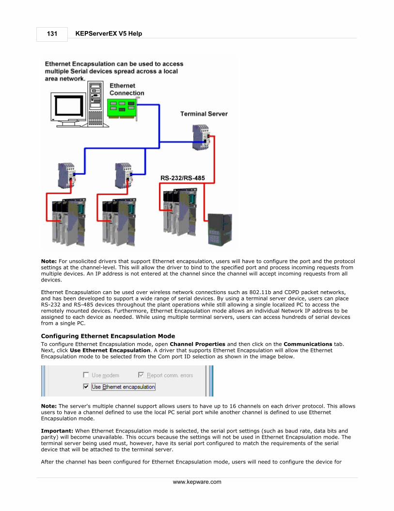
131
www.kepware.com
KEPServerEX V5 Help
Note: For unsolicited drivers that support Ethernet encapsulation, users will have to configure the port and the protocolsettings at the channel-level. This will allow the driver to bind to the specified port and process incoming requests frommultiple devices. An IP address is not entered at the channel since the channel will accept incoming requests from alldevices. Ethernet Encapsulation can be used over wireless network connections such as 802.11b and CDPD packet networks,and has been developed to support a wide range of serial devices. By using a terminal server device, users can placeRS-232 and RS-485 devices throughout the plant operations while still allowing a single localized PC to access theremotely mounted devices. Furthermore, Ethernet Encapsulation mode allows an individual Network IP address to beassigned to each device as needed. While using multiple terminal servers, users can access hundreds of serial devicesfrom a single PC.
Configuring Ethernet Encapsulation Mode
To configure Ethernet Encapsulation mode, open Channel Properties and then click on the Communications tab.Next, click Use Ethernet Encapsulation. A driver that supports Ethernet Encapsulation will allow the EthernetEncapsulation mode to be selected from the Com port ID selection as shown in the image below.
Note: The server's multiple channel support allows users to have up to 16 channels on each driver protocol. This allowsusers to have a channel defined to use the local PC serial port while another channel is defined to use EthernetEncapsulation mode. Important: When Ethernet Encapsulation mode is selected, the serial port settings (such as baud rate, data bits andparity) will become unavailable. This occurs because the settings will not be used in Ethernet Encapsulation mode. Theterminal server being used must, however, have its serial port configured to match the requirements of the serialdevice that will be attached to the terminal server. After the channel has been configured for Ethernet Encapsulation mode, users will need to configure the device for

132
www.kepware.com
KEPServerEX V5 Help
Ethernet operation. When a new device is added to the channel, the Ethernet Encapsulation settings can be used toselect an Ethernet IP address, an Ethernet Port number and the Ethernet protocol.
How To... Resolve Comm Issues When the DNS/DHCP Device Connected to the Serveris Power Cycled
Certain drivers support DNS/DHCP resolution for connectivity. These devices also allow users to assign unique Domain/Network names for identification purposes. When starting and connecting to the network, the devices will request an IPaddress from the Network DNS server. This process of resolving a domain name to an IP address for connectivity takestime; thus, for greater speed, the OS will cache all of the resolved IP/Domain names and then re-use them. Theresolved names are held in cache for two hours by default.
If The Server Fails to Re-Connect to a Device
This issue normally occurs when the name of the IP address (associated with the device's Domain/Network) changes. Ifthe change is a result of the device being power cycled, it will acquire a new IP. It could, however, also be a result ofthe IP being changed on the device manually. In both cases, the IP address that was being used no longer exists.
Resolving the Problem
The server automatically flushes the cache every 30 seconds; thus forcing the IP to be resolved. If this does not resolvethe issue, users can manually flush the cache by typing the command string "ipconfig /flushdns" in the PC's commandprompt. Note: For more information, refer to the following Microsoft Support article Disabling and Modifying Client SideDNS Caching.
How To... Allow Desktop Interactions
Some communication interfaces require the server to interact with the desktop. For example, Windows Messaging Layeris used by DDE and FastDDE. It is important, however, that the operating system be taken into consideration whenchoosing how to communicate with the desktop.
Windows Vista, Windows Server 2008 and Later Operating Systems
In Windows Vista, Windows Server 2008 and later operating systems, services run in an isolated session that isinaccessible to users logged on to the console. These operating systems require that the process mode be set toInteractive. This allows the Runtime to run in the same user account as the current user. For information on changingthe process mode, refer to Settings - Runtime Process.
Windows XP, Windows Server 2003 and Earlier Operating Systems
In Windows XP, Windows Server 2003 and earlier operating systems, the process mode can remain set as a SystemService. The Runtime's service, however, must be allowed to interact with the desktop. This is the preferred mode ofoperation since a user is not required to be logged on to the console in order for the server to start. For information onallowing a service to interact with the desktop, follow the instructions below. Note: These service settings only apply when the server is running in Service Mode.
1. Launch the Services snap-in, which is part of the Microsoft Management Console. To do so, click Start | Run. Then, type "services.msc" and click OK.
2. Next, locate the server by its name in the list of services. Open its context menu and select Properties.
3. Select the Log On tab.
4. Check Allow service to interact with desktop and then click Apply.
5. Click OK to exit.
6. Next, locate the Administration icon. Open its context menu and select Stop Runtime Service and then StartRuntime Service.
See Also: Accessing the Administration Menu
Error Descriptions
The following error/warning messages may be generated. Click on the link for a description of the message.
Server Runtime Error Messages
133
www.kepware.com
KEPServerEX V5 Help
'<driver name>' device driver was not found or could not be loaded
'<server name>' Server Started
'<server runtime>' successfully configured to run as a system service
'<server runtime>' successfully removed from the service control manager database
Attempt to add DDE item '<item name>' failed
Attempt to add FastDDE/SuiteLink item '<tag name>' failed
Attempt to add OPC client item '<item name>' failed
Attempting to automatically generate tags for device '<device name>'
Auto generation for tag '<tag name>' already exists and will not be overwritten
Auto generation produced too many overwrites, stopped posting error messages
Channel diagnostics started on channel '<channel name>'
Channel diagnostics stopped on channel '<channel name>'
Completed automatic tag generation for device '<device name>'
Configuration session assigned to '<user name>' as Default User has ended
Configuration session assigned to '<user name>' demoted to Read Only
Configuration session assigned to '<user name>' promoted toWrite Access
Configuration session started by '<user name>'
Configuration TCP/IP port number changed to '<port number>'
Data collection is '<enabled/disabled>' on device '<device name>'
DDE client attempt to add topic '<topic>' failed
Delete object '<item name>' failed
Demo timer started. '<days>' '<hours>' '<minutes>' '<seconds>'
Demo timer updated. '<time remaining>'
Demonstration time period has expired
Device '<device name>' has been auto-demoted
Device '<device name>' has been auto-promoted to determine if communications can be re-established
Failed to upload project XML
FLEXnet Licensing Service must be enabled to process your license
Module '<module>' is unsigned or has a corrupt signature
Move object '<group>' to '<group>' failed
No device driver DLLs were loaded
Rejecting attempt to delete referenced object '<item name>'
Rejecting attempt to move referenced object '<item name>'
Runtime project replaced from '<project location>'
Simulation mode is '<enabled/disabled>' on device '<device name>'
Starting '<driver name>' device driver
Starting '<plug-in name>' plug-in
Stopping '<driver name>' device driver
Stopping '<plug-in name>' plug-in
The tier information for feature '<feature>' is invalid
Unable to generate a tag database for device '<device name>'. Reason: '<reason>'
Unable to generate a tag database for device '<device name>'. The device is not responding
Unable to load project '<project name>'
Unable to write to item '<item name>'
Update of object '<object>' failed
Write request rejected on item reference '<item name>' since the device it belongs to is disabled
Write request rejected on Read Only item reference '<item name>'
Server Configuration Error Messages
'<device name>' device driver loaded successfully
'<driver name>' device driver unloaded from memory
'<driver name>' device driver was not found or could not be loaded
'<driver name>' driver does not currently support XML persistence

134
www.kepware.com
KEPServerEX V5 Help
'<plug-in>' plug-in was not found or could not be loaded
A client application has '<enabled/disabled>' auto-demotion on device '<device name>'
Closing project '<project name>'
Created backup of project '<project name>' to '<file location>'
Duplicate Channel Wizard page ID '<ID number>' detected
Error importing CSV tag record '<record number>': '<tag name>' is not a valid tag group name
Error importing CSV tag record '<record number>': '<tag name>' is not a valid tag name
Error importing CSV tag record '<record number>': Missing address
Error importing CSV tag record '<record number>': Tag or group name exceeds 256 characters
Failed to reset channel diagnostics
Failed to retrieve Runtime project
Invalid Ethernet encapsulation IP '<IP address>'
Invalid or missing Modem Configuration on channel '<channel name', substituting '<modem>'
Invalid XML document '<XML name>'
Maximum channel count exceeded for the lite version '<driver name>' driver license
Maximum device count exceeded for the lite version '<driver name>' driver license
Maximum Runtime tag count exceeded for the lite version '<driver name>' driver license
Modem initialization failed on channel '<channel name>'
Opening project '<project name>'
Required schema file '<schema name>' not found
Runtime project update failed
Starting OPC diagnostics
Stopping OPC diagnostics
Unable to add channel due to driver-level failure
Unable to add device due to driver-level failure
Unable to backup project file to '<file name/location>'
Unable to backup project file to '<file path>'
Unable to launch OPC Quick Client [Path: '<path>' OS Error: '<error>']
Unable to load driver DLL '<driver name>'
Unable to load the '<driver name>' driver because more than one copy exists ('<driver name>' and'<driver name>'
Unable to use network adapter '<adapter>' on channel '<channel name>'. Using default network adapter
Validation error on '<tag name>': Invalid scaling parameters
General Operation System Error Messages
, Error control
, Forced error control
, Hardware flow control
, Software flow control
Dialing '<phone number>' on line '<modem name>'
Dialing aborted on '<modem name>'
Dialing on line '<modem name>' cancelled by user
Failed to open modem line '<modem name>' [TAPI error]
Hardware error on line '<modem name>'
Incoming call detected on line '<modem name>'
Line '<modem name>' connected
Line '<modem name>' connected at '<baud rate>' baud
Line '<modem name>' disconnected
Line '<modem name>' is already in use
Line dropped at remote site on '<modem name>'
Modem line closed: '<modem name>'
Modem line opened: '<modem name>'
Modem to Modem DCE: '<connection parameters>'
MODEMSETTINGS unavailable
135
www.kepware.com
KEPServerEX V5 Help
No comm handle provided on connect for line '<modem name>'
No dial tone on '<modem name>'
Remote line is busy on '<modem name>'
Remote line is not answering on '<modem name>'
TAPI configuration has changed, reinitializing...
TAPI line initialization failed: '<modem name>'
The phone number is invalid '<phone number>'
Unable to apply Modem Configuration on line '<modem name>'
Unable to dial on line '<modem name>'
Unable to start Net DDE
iFIX Error Messages
Attempt to add iFIX PDB item '< item name>' failed
Failed to enable iFIX PDB support for this server [OS Error = n]
Unable to enable iFIX PDB support for this server
Unable to read '<tag name>' on device '<channel name/device name>'
Server Runtime Error Messages
The following error/warning messages may be generated. Click on the link for a description of the message.
Server Runtime Error Messages
'<driver name>' device driver was not found or could not be loaded
'<server name>' Server Started
'<server runtime>' successfully configured to run as a system service
'<server runtime>' successfully removed from the service control manager database
Attempt to add DDE item '<item name>' failed
Attempt to add FastDDE/SuiteLink item '<tag name>' failed
Attempt to add OPC client item '<item name>' failed
Attempting to automatically generate tags for device '<device name>'
Auto generation for tag '<tag name>' already exists and will not be overwritten
Auto generation produced too many overwrites, stopped posting error messages
Channel diagnostics started on channel '<channel name>'
Channel diagnostics stopped on channel '<channel name>'
Completed automatic tag generation for device '<device name>'
Configuration session assigned to '<user name>' as Default User has ended
Configuration session assigned to '<user name>' demoted to Read Only
Configuration session assigned to '<user name>' promoted toWrite Access
Configuration session started by '<user name>'
Configuration TCP/IP port number changed to '<port number>'
Data collection is '<enabled/disabled>' on device '<device name>'
DDE client attempt to add topic '<topic>' failed
Delete object '<item name>' failed
Demo timer started. '<days>' '<hours>' '<minutes>' '<seconds>'
Demo timer updated. '<time remaining>'
Demonstration time period has expired
Device '<device name>' has been auto-demoted
Device '<device name>' has been auto-promoted to determine if communications can be re-established
Failed to upload project XML
FLEXnet Licensing Service must be enabled to process your license
Module '<module>' is unsigned or has a corrupt signature
Move object '<group>' to '<group>' failed
No device driver DLLs were loaded
Rejecting attempt to delete referenced object '<item name>'

136
www.kepware.com
KEPServerEX V5 Help
Rejecting attempt to move referenced object '<item name>'
Runtime project replaced from '<project location>'
Simulation mode is '<enabled/disabled>' on device '<device name>'
Starting '<driver name>' device driver
Starting '<plug-in name>' plug-in
Stopping '<driver name>' device driver
Stopping '<plug-in name>' plug-in
The tier information for feature '<feature>' is invalid
Unable to generate a tag database for device '<device name>'. Reason: '<reason>'
Unable to generate a tag database for device '<device name>'. The device is not responding
Unable to load project '<project name>'
Unable to write to item '<item name>'
Update of object '<object>' failed
Write request rejected on item reference '<item name>' since the device it belongs to is disabled
Write request rejected on Read Only item reference '<item name>'
'<driver name>' device driver was not found or could not be loaded
Error Type:
Warning
Possible Cause:
A project using a driver that has not been installed or that is not compatible with the current server/driver version wasstarted but could not properly launch.
Solution:
1. If the driver is not installed, re-run the install and select the driver.2. If the driver is installed, verify the version that the project was created with and install a compatible version on therunning PC.
Note:
Every attempt is made to ensure backwards compatibility in the server so that projects created in older versions maybe loaded in newer versions. However, since new versions of the server and driver may have properties andconfigurations that do not exist in older version, users may not be able to open or load a project created in a newerversion of the server in an older version.
'<server name>' Server Started
Error Type:
Information
Source:
Runtime
Possible Cause:
The server Runtime has started successfully.
Solution:
N/A.
'<server runtime>' successfully configured to run as a system service
Error Type:
Information
Possible Cause:
The server runtime process has been switched from "Interactive" to "System service" mode.

137
www.kepware.com
KEPServerEX V5 Help
Solution:
None.
'<server runtime>' successfully removed from the service control manager database
Error Type:
Information
Possible Cause:
The server runtime process has been switched from "System Service" to "Interactive" mode.
Solution:
None.
Attempt to add DDE item '<item name>' failed
Error Type:
Error
Source:
Runtime
Possible Cause:
An attempt to add an item from a DDE client failed.
Solution:
1. If attempting to add an item dynamically to a tag group that is not supported in the server: Add Dynamic Tags to thedevice level only.2. If attempting to add an item dynamically but used the incorrect address syntax: Verify the syntax and try again.3. If attempting to add an item that was not created as a static tag in the server: Add the tag in the server and then tryadding the item from the client.4. If attempting to add an item but used incorrect syntax: Correct the syntax and try again.
Attempt to add FastDDE/SuiteLink item '<tag name>' failed
Error Type:
Error
Source:
Runtime
Possible Cause:
1. The user attempted to add an item from a FastDDE/Suitelink client that was not a static tag in the server.2. The user attempted to add an item from a FastDDE/Suitelink client that had incorrect syntax.
Solution:
1. Check the item syntax and correct if necessary.2. Verify that the item is a valid address in the driver. If not, either use the correct address or remove the request.3. Verify that the static tag exists in the project. If not, either add it or remove the request.
Attempt to add OPC Client item '<item name>' failed
Error Type:
Error
Source:
Runtime
138
www.kepware.com
KEPServerEX V5 Help
Possible Cause:
An attempt to add an item from an OPC client failed.
Solution:
1. If attempting to add an item dynamically to a tag group that is not supported in the server: Add Dynamic Tags to thedevice level only.2. If attempting to add an item dynamically but used the incorrect address syntax: Verify the syntax and try again.3. If attempting to add an item that was not created as a static tag in the server: Add the tag in the server and then tryadding the item from the client.4. If attempting to add an item but used incorrect syntax: Correct the syntax and try again.
Attempting to automatically generate tags for device '<device name>'
Error Type:
Information
Source:
Runtime
Possible Cause:
The server is attempting to generate tags for the specified device.
Solution:
N/A.
Auto generation for tag '<tag name>' already exists and will not be overwritten
Error Type:
Warning
Source:
Runtime
Possible Cause:
Although the server is regenerating tags for the tag database, it has been set not to overwrite tags that already exist.
Solution:
If this is not the desired action, change the setting in the Database Creation Properties dialog.
Auto generation produced too many overwrites, stopped posting error messages
Error Type:
Warning
Source:
Runtime
Possible Cause:
To keep from filling the error log, the server has stopped posting error messages on tags that cannot be overwrittenduring automatic tag generation.
Solution:
N/A.
Channel diagnostics started on channel '<channel name>'
Error Type:
139
www.kepware.com
KEPServerEX V5 Help
Information
Source:
Runtime
Possible Cause:
Channel diagnostics have started successfully on the channel.
Solution:
N/A.
Channel diagnostics stopped on channel '<channel name>'
Error Type:
Information
Source:
Runtime
Possible Cause:
Channel diagnostics have stopped successfully on the channel.
Solution:
N/A.
Completed automatic tag generation for device '<device name>'
Error Type:
Information
Source:
Runtime
Possible Cause:
The server successfully generated tags for the tag database.
Solution:
N/A.
Configuration session assigned to '<user name>' as Default User has ended
Error Type:
Warning
Source:
Runtime
Possible Cause:
The specified user connected to the Runtime has ended the session.
Solution:
None.
Configuration session assigned to '<user name>' demoted to Read Only
Error Type:
Information

140
www.kepware.com
KEPServerEX V5 Help
Source:
Runtime
Possible Cause:
The connected user has been idle for more than 15 minutes, and so the server automatically demoted them.
Solution:
When connected with the Configuration, do not leave the connection idle if in write access mode.
Configuration session assigned to '<user name>' promoted to Write Access
Error Type:
Information
Source:
Runtime
Possible Cause:
A user that was connected to the Runtime with Write Access has disconnected or demoted due to being idle.
Solution:
N/A.
Configuration session started by '<user name>'
Error Type:
Warning
Source:
Runtime
Possible Cause:
A user on the local or remote PC has started a configuration session using a user login with Read/Write access to theRuntime project.
Solution:
The first user to connect to the Runtime with a Configuration will have Read/Write access to the Runtime all other usersto connect will have Read Only access.
Configuration TCP/IP port number changed to '<port number>'
Error Type:
Information
Source:
Runtime
Possible Cause:
The port number that is used to connect the Configuration to the Runtime has been changed.
Solution:
The port was changed in the Administration settings. Change the port number in the Configuration Options in theRuntime Connection Options to match the new Runtime port.
Data collection is '<enabled/disabled>' on device '<device name>'
Error Type:

141
www.kepware.com
KEPServerEX V5 Help
Information
Source:
Runtime
Possible Cause:
1. A client application has programmatically Enabled/Disabled Data Collection for the specified device.2. The user's Configuration has Enabled/Disabled Data Collection for the specified device.
Solution:
N/A.
DDE client attempt to add topic '<topic>' failed
Error Type:
Error
Source:
Runtime
Possible Cause:
An attempt was made by a DDE client to add or reference a topic that does not exist.
Solution:
1. Verify that an alias has been created in the alias map with the same name as the topic.2. The global topic is '_ddeData.' If using it, make sure to use the correct syntax. It is not case sensitive.
Delete object '<item name>' failed
Error Type:
Warning
Source:
Runtime
Possible Cause:
An attempt to remove an object failed.
Solution:
Reference the item by something else. The user may not have privileges to remove the object.
Demo timer started. '<days>' '<hours>' '<minutes>' '<seconds>'
Error Type:
Warning
Source:
Runtime
Possible Cause:
The server has started in demo mode with the specified time remaining in the demo period.
Solution:
1. If evaluating the server, no action needs to be taken.2. If this is a production machine, activate the product licenses for the installed components before the demo timeperiod expires.
142
www.kepware.com
KEPServerEX V5 Help
Demo timer updated. '<time remaining>'
Error Type:
Warning
Possible Cause:
None.
Solution:
None.
Demonstration time period has expired for <Feature Name>
Error Type:
Warning
Source:
Runtime
Possible Cause:
The server was running in demo mode, but the demo period has expired.
Solution:
1. Obtain a license for the drivers or plug-ins that were functioning as a demo. For more information, refer to "SupportInformation," which may be accessed either from the server's Help menu or from the server's Administration menu(located in the System Tray).2. Reset the two-hour demo period by stopping and restarting the server Runtime. To do so, select "Stop RuntimeService" and then "Start Runtime Service" from the server's Administration menu.
Notes:
1. For information on managing licenses, refer to the License Utility help file.2. Often, an unlicensed (demo) driver or plug-in is temporarily activated either prior to or after a project is loaded withlicensed drivers or plug-ins. This will trigger the two-hour demo period, which will stop the server Runtime project onceit expires. To properly restart a licensed project without triggering the demo period, load a project which only useslicensed drivers and plug-ins. Then, stop and the start the server Runtime from the Administration menu.
Device '<device name>' has been auto-demoted
Error Type:
Warning
Source:
Runtime
Possible Cause:
Communications with the specified device have failed. The device has been demoted from the poll cycle.
Solution:
1. If the device fails to reconnect, investigate the reasons behind the communications loss and then correct it.2. To stop the device from being demoted, diasbled Auto-Demotion.
Device '<device name>' has been auto-promoted to determine if communications canbe re-established
Error Type:
Information
Source:
Runtime

143
www.kepware.com
KEPServerEX V5 Help
Possible Cause:
If a device that was previously demoted from the poll cycle has been promoted, check to see if it is now available.
Solution:
N/A.
Notes:
If communications fail, the device will be demoted again.
Failed to upload project XML
Error Type:
Error
Source:
Runtime
Possible Cause:
1. The driver, driver schema file or both are not installed.2. The project was saved in a newer version of the server or one that has incompatible schema fields.
Solution:
1. Verify that the driver and schema files are installed.2. Compare the versions of the server in which the file was created against the version in which it is being loaded.
FLEXnet Licensing Service must be enabled to process your license. Runtimereferences are limited to demo operation
Error Type:
Warning
Source:
Runtime
Possible Cause:
The user is attempting to license a driver or component without the Runtime enabled and running.
Solution:
Start the Runtime Service and then re-attempt licensing.
Module '<module>' is unsigned or has a corrupt signature. Runtime references arelimited to demo operation
Error Type:
Warning
Source:
Runtime
Possible Cause:
Runtime attempted to validate a license certificate and failed.
Solution:
1. Ensure that the license subscriptions are updated.2. Ensure that the drivers or suites being used are properly licensed.
Note:

144
www.kepware.com
KEPServerEX V5 Help
Until the problem is corrected, the Runtime project will run in Demo mode.
Move object '<group>' to '<group>' failed
Error Type:
Warning
Source:
Runtime
Possible Cause:
An attempt to move a tag or group to another group or device failed because the item is referenced by another object.
Solution:
The object may be referenced by another object, although the user may not have the privileges to make the change.
No device driver DLLs were loaded
Error Type:
Error
Source:
Runtime
Possible Cause:
The drivers may not have been installed or updated when the server was installed.
Solution:
1. Drivers are synchronized with the server build. Drivers from previous builds may not have required changes;therefore, they cannot be loaded when the server starts. Re-run the server install.2. The drivers folder is empty; therefore, no drivers could be loaded. Re-run the server install.
Rejecting attempt to delete referenced object '<item name>'
Error Type:
Warning
Source:
Runtime
Possible Cause:
An attempt was made to remove an object from the server that is being referenced from some other place.
Solution:
Remove the reference and then re-attempt to remove the object.
Rejecting attempt to move referenced object '<item name>'
Error Type:
Warning
Source:
Runtime
Possible Cause:
An attempt was made to move an object and failed.

145
www.kepware.com
KEPServerEX V5 Help
Solution:
The object may be referenced by another object, although the user may not have the privileges to make the change.
Runtime project replaced from '<project location>'
Error Type:
Information
Source:
Runtime
Possible Cause:
A new project was selected for the Runtime to run.
Solution:
N/A.
Simulation mode is '<enabled/disabled>' on device '<device name>'
Error Type:
Information
Source:
Runtime
Possible Cause:
The user's Configuration has Enabled/Disabled Simulation mode for the specified device.
Solution:
N/A.
Starting '<driver name>' device driver
Error Type:
Warning
Possible Cause:
The server successfully loaded and started a driver that will be used in the running project.
Starting '<plug-in name>' plug-in
Error Type:
Information
Source:
Runtime
Possible Cause:
The server started and successfully loaded the plug-in for use.
Solution:
N/A.
Stopping '<driver name>' device driver
Error Type:
Warning

146
www.kepware.com
KEPServerEX V5 Help
Possible Cause:
The server successfully stopped the specified driver in preparation for server shutdown or project change.
Solution:
None.
Stopping '<plug-in name>' plug-in
Error Type:
Information
Source:
Runtime
Possible Cause:
The server is shutting down and the plug-in was successfully un-loaded.
Solution:
N/A.
The tier information for feature '<feature>' is invalid
Error Type:
Error
Source:
Runtime
Possible Cause:
This is a custom licensed product for OEMs and vendors. An error has occurred loading the custom licensing string.
Solution:
Contact the OEM/Vendor for more information and support.
Unable to generate a tag database for device '<device name>'. Reason: '<reason>'
Error Type:
Warning
Source:
Runtime
Possible Cause:
The server attempted to generate tags for the specified device and failed with the specified reason.
Solution:
Correct the reason of failure and then retry the tag generation.
Unable to generate a tag database for device '<device name>'. The device is notresponding
Error Type:
Warning
Source:
Runtime

147
www.kepware.com
KEPServerEX V5 Help
Possible Cause:
The server attempted to generate tags from the physical device and failed because the device did not respond to thecommunications request.
Solution:
1. Verify that the device is powered on and that the PC running (so that the server can connect to it).2. Verify that all cabling is correct.3. Verify that the Device IDs are correct.
Unable to load project '<project name>'
Error Type:
Warning
Possible Cause:
The project was created in a server version that is not compatible with version that trying to load it.
Solution:
Typically this happens when a project was created in a newer version of the server and it is being opened in an olderversion.
Note:
Every attempt is made to ensure backwards compatibility in the server so that projects created in older versions maybe loaded in newer versions. However, since new versions of the server and driver may have properties andconfigurations that do not exist in older version, users may not be able to open or load a project created in a newerversion of the server in an older version.
Unable to write to item '<item name>'
Error Type:
Warning
Source:
Runtime
Possible Cause:
The client application sent a write to an item and it was rejected.
Solution:
1. The tag may have Read/Write access in the server even though the device only allows reads. Verify that the item isRead Only and change the access Writes in the server. Additionally, change the action in the connected clientapplication.2. The server may have timed-out in demo mode. Save and then restart the server.
Update of object '<object>' failed
Error Type:
Warning
Source:
Runtime
Possible Cause:
An attempt was made to update an object in the project that is neither accessible nor available.
Solution:
Save the project to a different location.

148
www.kepware.com
KEPServerEX V5 Help
Write request rejected on item reference '<item name>' since the device it belongs tois disabled
Error Type:
Warning
Source:
Runtime
Possible Cause:
An attempt was made to write to a tag that is on a disabled device.
Solution:
Devices can be programmatically disabled, thus indicating to the server that it should not be communicated with at thistime. To enable it, write to the _Enabled system tag. Alternatively, check the Enable data collection check box in DeviceProperties.
Write request rejected on Read Only item reference '<item name>'
Error Type:
Warning
Source:
Runtime
Possible Cause:
An attempt was made by the client application to write to a Read Only item.
Solution:
1. Change the tag's access to Read/Write (if supported).2. Change the client application so that it does not attempt to write to the item.
Server Configuration Error Messages
The following error/warning messages may be generated. Click on the link for a description of the message.
Server Configuration Error Messages
'<device name>' device driver loaded successfully
'<driver name>' device driver unloaded from memory
'<driver name>' device driver was not found or could not be loaded
'<driver name>' driver does not currently support XML persistence
'<plug-in>' plug-in was not found or could not be loaded
A client application has '<enabled/disabled>' auto-demotion on device '<device name>'
Closing project '<project name>'
Created backup of project '<project name>' to '<file location>'
Duplicate Channel Wizard page ID '<ID number>' detected
Error importing CSV tag record '<record number>': '<tag name>' is not a valid tag group name
Error importing CSV tag record '<record number>': '<tag name>' is not a valid tag name
Error importing CSV tag record '<record number>': Missing address
Error importing CSV tag record '<record number>': Tag or group name exceeds 256 characters
Failed to reset channel diagnostics
Failed to retrieve Runtime project
Invalid Ethernet encapsulation IP '<IP address>'
Invalid or missing Modem Configuration on channel '<channel name', substituting '<modem>'
Invalid XML document '<XML name>'
Maximum channel count exceeded for the lite version '<driver name>' driver license
Maximum device count exceeded for the lite version '<driver name>' driver license
149
www.kepware.com
KEPServerEX V5 Help
Maximum Runtime tag count exceeded for the lite version '<driver name>' driver license
Modem initialization failed on channel '<channel name>'
Opening project '<project name>'
Required schema file '<schema name>' not found
Runtime project update failed
Starting OPC diagnostics
Stopping OPC diagnostics
Unable to add channel due to driver-level failure
Unable to add device due to driver-level failure
Unable to backup project file to '<file name/location>'
Unable to backup project file to '<file path>'
Unable to launch OPC Quick Client [Path: '<path>' OS Error: '<error>']
Unable to load driver DLL '<driver name>'
Unable to load the '<driver name>' driver because more than one copy exists ('<driver name>' and'<driver name>'
Unable to use network adapter '<adapter>' on channel '<channel name>'. Using default network adapter
Validation error on '<tag name>': Invalid scaling parameters
'<device name>' device driver loaded successfully
Error Type:
Warning
Possible Cause:
The Configuration was able to successfully load the driver into its workspace.
Solution:
N/A.
'<driver name>' device driver unloaded from memory
Error Type:
Information
Source:
Configuration
Possible Cause:
The driver was unloaded from the server's memory space because it was no longer needed.
Solution
N/A.
'<driver name>' device driver was not found or could not be loaded
Error Type:
Error
Source:
Configuration
Possible Cause:
An attempt was made to load a project with a channel using the specified driver which could not be found or loaded. 1. If the project has been moved from one PC to another, the required drivers may have not been installed yet.2. The specified driver may have been removed from the installed server.

150
www.kepware.com
KEPServerEX V5 Help
3. The specified driver may be the wrong version for the installed server version.
Solution:
1. Re-run the server install and add the required drivers.2. Re-run the server install and re-install the specified drivers.3. Ensure that a driver has not been placed in the installed server directory (which is out of sync with the serverversion).
'<driver name>' driver does not currently support XML persistence
Error Type:
Warning
Source:
Configuration
Possible Cause:
The specified driver does not support XML formatting.
Solution:
1. Save the project in .opf format.
'<plug-in>' plug-in was not found or could not be loaded
Error Type:
Error
Source:
Configuration
Possible Cause:
The server project being loaded is using a plug-in that cannot be found.
Solution:
Re-run the server install and select the specified plug-in for installation.
A client application has '<enabled/disabled>' auto-demotion on device '<devicename>'
Error Type:
Information
Source:
Configuration
Possible Cause:
A client application that is connected to the server has enabled or disabled Auto Demotion on the specified device.
Solution:
To restrict the client application from doing this, disable its ability to write to System-level tags through the OPC DASettings.
Closing project '<project name>'
Error Type:
Information
Source:

151
www.kepware.com
KEPServerEX V5 Help
Configuration
Possible Cause:
The specified project was closed.
Solution:
N/A.
Created backup of project '<project name>' to '<file location>'
Error Type:
Information
Source:
Configuration
Possible Cause:
The server was able to successfully backup the server project.
Solution:
N/A.
Duplicate Channel Wizard page ID '<ID number>' detected
Error Type:
Error
Source:
Configuration
Possible Cause:
This message indicates that two Channel Wizard pages were created with the same ID.
Solution:
Contact Technical Support.
Error importing CSV tag record '<record number>': '<tag name>' is not a valid taggroup name
Error Type:
Warning
Source:
Configuration
Possible Cause:
A tag group has been imported in the CSV file that is incorrectly formatted.
Solution:
Correct the syntax in the CSV file and then re-import.
Note:
Tag group names may not start with '_' (Underscores), '.' (Periods) or ' ' (spaces).
Error importing CSV tag record '<record number>': '<tag name>' is not a valid tagname

152
www.kepware.com
KEPServerEX V5 Help
Error Type:
Warning
Source:
Configuration
Possible Cause:
A tag has been imported in the CSV file that is incorrectly formatted.
Solution:
Correct the syntax in the CSV file and then re-import.
Note:
Tag names may not start with '_' (Underscores), '.'(Periods) or ' ' (spaces).
Error importing CSV tag record '<record number>': Missing address
Error Type:
Warning
Source:
Configuration
Possible Cause:
An attempt was made to import a CSV file. The tag was configured in the CSV without an address specified in theaddress field.
Solution:
Add an address to the specified record and re-run the CSV import.
Error importing CSV tag record '<record number>': Tag or group name exceeds 256characters
Error Type:
Warning
Source:
Configuration
Possible Cause:
A tag or tag group has been imported from a CSV file that has a name exceeding the 256 character limit.
Solution:
Correct the specified name in the CSV file and then re-import.
Note:
The tag record is calculated from the List of tags in the CSV file, beginning with the first item listed.
Failed to reset channel diagnostics
Error Type:
Warning
Source:
Configuration
Possible Cause:
153
www.kepware.com
KEPServerEX V5 Help
A failed attempt was made to reset the Channel Diagnostics data.
Solution:
Ensure that diagnostics are enabled for this channel.
Failed to retrieve Runtime project
Error Type:
Error
Source:
Configuration
Possible Cause:
The Configuration connected to the Runtime but was unable to load the project for editing.
Solution:
1. The Configuration could be a different version than the Runtime. Ensure that the client and Runtime versions canwork together. If not, install the correct Configuration .2. The project loaded by the Runtime may have been deleted. Verify that the project still exists; if it does not, restoreit.
Invalid Ethernet encapsulation IP '<IP address>'
Error Type:
Warning
Source:
Configuration
Possible Cause:
The IP address that is specified for a device on an Ethernet Encapsulated channel is not a valid IP address.
Solution:
Correct the IP in the XML file and then re-load the project.
Note:
This error occurs when loading XML formatted projects. These projects have usually been created or edited with a thirdparty XML software.
Invalid or missing Modem Configuration on channel '<channel name', substituting'<modem>'
Error Type:
Warning
Source:
Configuration
Possible Cause:
A server project was loaded that uses a modem unavailable on this PC.
Solution:
1. Change the Modem Configuration in the project to use a supported modem.2. Add the specified modem to the PC's Configuration.

154
www.kepware.com
KEPServerEX V5 Help
Invalid XML document '<XML name>'
Error Type:
Error
Source:
Configuration
Possible Cause:
The server attempted to open a project formatted with XML and was unable to parse the XML file.
Solution:
If the server project was edited using a third party XML editor, verify that the format is correct via the schemas for theserver and drivers.
Maximum channel count exceeded for the lite version '<driver name>' driver license
Error Type:
Warning
Source:
Configuration
Possible Cause:
The specified driver was activated with a lite license, which limits the number of channels that can be configured.
Solution:
1. Verify the number of channels authorized by the license. Then, correct the project design to use only that number ofchannels.2. If more channels are needed or the lite activation is incorrect, contact the sales representative about upgrading thelicense to a version that will support the number of desired channels.
Maximum device count exceeded for the lite version '<driver name>' driver license
Error Type:
Warning
Source:
Configuration
Possible Cause:
The specified driver was activated with a lite license, which limits the number of devices that can be configured.
Solution:
1. Verify the number of devices authorized by the license. Then, correct the project design to use only that number ofchannels.2. If more devices are needed or the lite activation is incorrect, contact the sales representative about upgrading thelicense to a version that will support the number of desired devices.
Maximum Runtime tag count exceeded for the lite version '<driver name>' driverlicense
Error Type:
Error
Source:
Configuration
Possible Cause:

155
www.kepware.com
KEPServerEX V5 Help
The specified driver was activated with a lite license, which limits the number of tags that can be configured.
Solution:
1. Verify the number of tags authorized by the license and then correct the project design to use only that number ofchannels.2. If more tags are needed or if the lite activation is incorrect, contact the sales representative about upgrading thelicense to a version that will support the number of desired tags.
Modem initialization failed on channel '<channel name>'
Error Type:
Error
Source:
Configuration
Possible Cause:
A server made a failed attempt to initialize the modem assigned to the specified channel.
Solution:
Refer to the additional events that will be posted with details on the initialization errors.
Opening project '<project name>'
Error Type:
Information
Source:
Configuration
Possible Cause:
The specified project was opened.
Solution:
N/A.
Required schema file '<schema name>' not found
Error Type:
Error
Source:
Configuration
Possible Cause:
A project formatted with XML was loaded but the specified schema file was not found in the schemas folder.
Solution:
Re-run the server install and make sure that all the drivers are updated. This will re-install any missing schema files.
Runtime project update failed
Error Type:
Error
Source:
Configuration

156
www.kepware.com
KEPServerEX V5 Help
Possible Cause:
The client attempted to update the Runtime project and failed.
Solution:
1. The user may not have permission to make changes to the project. Log in to the User Manager with the correct usercredentials.2. The project folder may be locked to changes. Verify that all users with access to the project have permissions in thefolder.
Starting OPC diagnostics
Error Type:
Information
Source:
Configuration
Possible Cause:
OPC diagnostics captures were started by a connected Configuration.
Solution:
N/A.
Stopping OPC diagnostics
Error Type:
Information
Source:
Configuration
Possible Cause:
OPC Diagnostics capturing were stopped by a connected Configuration.
Solution:
N/A.
Unable to add channel due to driver-level failure
Error Type:
Error
Source:
Configuration
Possible Cause:
An attempt was made to add a channel to the server and it failed due to issues in the driver.
Solution:
1. Refer to the additional messages that will be posted with information on the driver-level error.2. If necessary, contact Technical Support for additional help.
Unable to add device due to driver level failure
Error Type:
Error
Source:

157
www.kepware.com
KEPServerEX V5 Help
Configuration
Possible Cause:
An attempt was made to create a device in a server project, but it failed due to an issue in the driver.
Solution:
Refer to the additional error messages that follow, in order to learn about the driver error.
Unable to backup project file to '<file name/location>'
Error Type:
Error
Source:
Configuration
Possible Cause:
The server was unable to backup the project to the specified location.
Solution:
Ensure access permissions to the destination folder.
Unable to backup project file to '<file path>'
Error Type:
Error
Source:
Configuration
Possible Cause:
The server was unable to back up the server project to the specified file location.
Solution:
1. Ensure that the destination file is not locked by another application.2. Ensure that the destination file, along with the folder where it is located, have Read/Write access.
Note:
This error is most likely due to Read/Write access permissions.
Unable to launch OPC Quick Client [Path: '<path>' OS Error: '<error>']
Error Type:
Error
Source:
Configuration
Possible Cause:
An attempt was made to launch the OPC Quick Client from the Configuration and it failed.
Solution:
1. Verify that the OPC Quick Client is installed in the specified location. If not, re-run the server installation and select itfor installation.2. Verify that the required access rights to launch the OPC Quick Client from its specified location are had.3. Contact Technical Support for assistance in determining the fault from the OS Error.

158
www.kepware.com
KEPServerEX V5 Help
Unable to load driver DLL '<driver name>'
Error Type:
Error
Source:
Configuration
Possible Cause:
The specified driver could not be loaded when the project started.
Solution:
1. Verify the version of the driver that is installed. Check the OPC server's website to see if the driver version is for theversion of the server that is installed. If not, correct the server or re-run the server install.2. If the driver is found to be corrupted, delete it an dthen re-run the server install.
Note:
This problem is usually due to corrupted driver DLLs or drivers that are not in sync with the server version.
Unable to load the '<driver name>' driver because more than one copy exists ('<drivername>' and '<driver name>')
Error Type:
Error
Source:
Configuration
Possible Cause:
There are multiple versions of the driver DLL existing in the driver's folder in the server.
Solution:
Contact Technical support and verify which version should be installed for the version of the server being run. Removethe driver that is invalid and then restart the server and load the project.
Unable to use network adapter '<adapter>' on channel '<channel name>'. Usingdefault network adapter
Error Type:
Warning
Source:
Configuration
Possible Cause:
The network adapter specified in the project does not exist on this PC. Thus, the server will default to using the defaultnetwork adapter.
Solution:
Select the network adapter that will be used on the PC and then save the project.
See Also:
Channel Properties - Network Interface
Validation error on '<tag name>': Invalid scaling parameters
Error Type:
Warning

159
www.kepware.com
KEPServerEX V5 Help
Source:
Configuration
Possible Cause:
An attempt was made to set invalid scaling parameters on the specified tag.
Solution:
Correct the scaling parameters and then save the tag.
General Operation System Error Messages
The following error/warning messages may be generated. Click on the link for a description of the message.
General Operation System Error Messages
, Error control
, Forced error control
, Hardware flow control
, Software flow control
Dialing '<phone number>' on line '<modem name>'
Dialing aborted on '<modem name>'
Dialing on line '<modem name>' cancelled by user
Failed to open modem line '<modem name>' [TAPI error]
Hardware error on line '<modem name>'
Incoming call detected on line '<modem name>'
Line '<modem name>' connected
Line '<modem name>' connected at '<baud rate>' baud
Line '<modem name>' disconnected
Line '<modem name>' is already in use
Line dropped at remote site on '<modem name>'
Modem line closed: '<modem name>'
Modem line opened: '<modem name>'
Modem to Modem DCE: '<connection parameters>'
MODEMSETTINGS unavailable
No comm handle provided on connect for line '<modem name>'
No dial tone on '<modem name>'
Remote line is busy on '<modem name>'
Remote line is not answering on '<modem name>'
TAPI configuration has changed, reinitializing...
TAPI line initialization failed: '<modem name>'
The phone number is invalid '<phone number>'
Unable to apply Modem Configuration on line '<modem name>'
Unable to dial on line '<modem name>'
Unable to start Net DDE
, Error control
Error Type:
Information
Source:
TAPI Manager
Possible Cause:
Error control has been set in the Modem Configuration dialog.

160
www.kepware.com
KEPServerEX V5 Help
Solution:
N/A.
, Forced error control
Error Type:
Information
Source:
TAPI Manager
Possible Cause:
Forced Error control has been set in the Modem Configuration dialog
Solution:
N/A.
, Hardware flow control
Error Type:
Information
Source:
TAPI Manager
Possible Cause:
Hardware Flow control has been set in the Modem Configuration dialog.
Solution:
N/A.
, Software flow control
Error Type:
Information
Source:
TAPI Manager
Possible Cause:
Software Flow control has been set in the Modem Configuration dialog.
Solution:
N/A.
Dialing '<phone number>' on line '<modem name>'
Error Type:
Information
Source:
TAPI Manager
Possible Cause:
TAPI manager is dialing the specified number for the server.

161
www.kepware.com
KEPServerEX V5 Help
Solution:
N/A.
Dialing aborted on '<modem name>'
Error Type:
Information
Source:
TAPI Manager
Possible Cause:
Dialing was aborted by the user.
Solution:
N/A.
Dialing on line '<modem name>' cancelled by user
Error Type:
Information
Source:
TAPI Manager
Possible Cause:
The Server has canceled its request to dial a device on the specified line.
Solution:
N/A.
Failed to open modem line '<modem name>' [TAPI error]
Error Type:
Error
Source:
TAPI Manager
Possible Cause:
TAPI attempted to open the modem line for the server and encountered an error.
Solution:
Correct the specified error. Then, re-attempt to open the modem line.
Hardware error on line '<modem name>'
Error Type:
Warning
Source:
TAPI Manager
Possible Cause:
A hardware error was returned after a request was made for a tag in a device that will be connected to the modem.
Solution:

162
www.kepware.com
KEPServerEX V5 Help
Disable data collection on the device. Only enable it after the modem has connected to the destination modem.
Note:
The error will occur on first scan and will not be repeated.
Incoming call detected on line '<modem name>'
Error Type:
Information
Source:
TAPI Manager
Possible Cause:
The modem has detected an incoming call on phone line on which it is connected. If the modem is set to automaticallyanswer, it will answer the incoming call.
Solution:
N/A.
Line '<modem name>' connected
Error Type:
Information
Source:
TAPI Manager
Possible Cause:
The modem lines are connected.
Solution:
None available.
Line '<modem name>' connected at '<baud rate>' baud
Error Type:
Information
Source:
TAPI Manager
Possible Cause:
The modem connected to the dialed modem at the specified rate.
Solution:
N/A.
Line '<modem name>' disconnected
Error Type:
Information
Source:
TAPI Manager
Possible Cause:

163
www.kepware.com
KEPServerEX V5 Help
TAPI manager has disconnected the modem for the server.
Solution:
N/A.
Line '<modem name>' is already in use
Error Type:
Warning
Source:
TAPI Manager
Possible Cause:
An attempt was made to open the modem line but could not be completed because it was already open.
Solution:
Find the application that is currently holding the modem open. Then, either close or release it.
Line dropped at remote site on '<modem name>'
Error Type:
Information
Source:
TAPI Manager
Possible Cause:
The remote modem has hung up and dropped the call.
Solution:
N/A.
Modem line closed: '<modem name>'
Error Type:
Warning
Source:
TAPI Manager
Possible Cause:
The modem line was closed by the TAPI manager.
Solution:
This message is normally posted when a project is stopped and the driver no longer needs the modem line.
Modem line opened: '<modem name>'
Error Type:
Warning
Source:
TAPI Manager
Possible Cause:
The modem line was opened by the TAPI manager.

164
www.kepware.com
KEPServerEX V5 Help
Solution:
This message is normally posted when a project is started and the driver needs the modem line.
Modem to Modem DCE: '<connection parameters>'
Error Type:
Information
Source:
TAPI Manager
Possible Cause:
Modem connection is established to the remote modem.
Solution:
N/A.
MODEMSETTINGS unavailable
Error Type:
Information
Source:
TAPI Manager
Possible Cause:
The Modem Configuration dialog has been loaded but the modem settings for the selected modem are not accessible.
Solution:
If the modem was recently installed, try stopping and restarting the server. The PC may need to be rebooted in orderfor the modem settings to become available.
No comm handle provided on connect for line '<modem name>'
Error Type:
Warning
Source:
TAPI Manager
Possible Cause:
An attempt was made to connect to the modem line with no specified COMM handle.
Solution:
Make sure the modem is both installed and initialized correctly.
No dial tone on '<modem name>'
Error Type:
Information
Source:
TAPI Manager
Possible Cause:
There is no dial tone on the line.

165
www.kepware.com
KEPServerEX V5 Help
Solution:
1. Make sure that the modem is connected.2. The phone line may require a code or number to get an outside line or dial tone. Make sure that the Modem settingsare correctly set to automatically dial this number when a connection is made to the modem.
Remote line is busy on '<modem name>'
Error Type:
Information
Source:
TAPI Manager
Possible Cause:
The dialed location is busy.
Solution:
Hang up and then try again later.
Remote line is not answering on '<modem name>'
Error Type:
Information
Source:
TAPI Manager
Possible Cause:
The dialed modem is not answering the call.
Solution:
1. Hang up and then try again later.2. Verify that the remote modem is configured to answer calls.
TAPI configuration has changed, reinitializing...
Error Type:
Information
Source:
TAPI Manager
Possible Cause:
The TAPI Line configuration has changed. TAPI is now reinitializing the modem with the changes.
Solution:
None available.
TAPI line initialization failed: '<modem name>'
Error Type:
Warning
Source:
TAPI Manager
Possible Cause:

166
www.kepware.com
KEPServerEX V5 Help
The telephony service is not required to be running in order for the Runtime to start. When the service is disabled and aserial driver is added to the project, this error message is reported.
Solution:
1. If modem communications is not going to be used, no action is required.2. If modem communications is required, the telephony service will need to be started on the PC.
The phone number is invalid '<phone number>'
Error Type:
Information
Source:
TAPI Manager
Possible Cause:
The phone number entered and dialed is incorrectly formatted for the local or long distance settings.
Solution:
Open the Modem Configuration and verify the number formats required. Then, re-dial the number with the correctformat.
Unable to apply Modem Configuration on line '<modem name>'
Error Type:
Warning
Source:
TAPI Manager
Possible Cause:
TAPI Manager was unable to apply to Configuration changes to the server.
Solution:
1. Verify the cabling to the modem.2. Verify that the modem is set to accept Configuration changes.3. Verify that the modem is not being used by another application.
Unable to dial on line '<modem name>'
Error Type:
Information
Source:
TAPI Manager
Possible Cause:
The server is unable to have the modem dial the number because the modem is not in a state that allows dialing.
Solution:
In order to dial a number, the line must be idle. Monitor the _Mode Modem Tag and dial when it indicates an idle state.
Unable to start Net DDE
Error Type:
Warning
Source:

167
www.kepware.com
KEPServerEX V5 Help
DDE
Possible Cause:
1. The server project is configured to allow Net DDE but was unable to launch Net DDE.2. Net DDE Servers are not enabled to run as a service on this PC or have been completely disabled.
Solution:
1. Go to the Service manager and ensure that Net DDE services is enabled and set to automatically start.2. Check with the IT administrator and make sure that Net DDE services are allowed. If not, have the local policychanged to allow Net DDE.
iFIX Error Messages
The following error/warning messages may be generated. Click on the link for a description of the message.
iFIX Error Messages
Attempt to add iFIX PDB item '< item name>' failed
Failed to enable iFIX PDB support for this server [OS Error = n]
Unable to enable iFIX PDB support for this server
Unable to read '<tag name>' on device '<channel name/device name>'
Attempt to add iFIX PDB item '< item name>' failed
Error Type:
Information
Source:
NIO
Possible Cause:
The server was not able to add the NIO interface.
Solution:
The server could be in use by a client application. In this case, changes (such as, new interfaces) can be disabled.
Failed to enable iFIX PDB support for this server [OS Error = n]
Error Type:
Information
Source:
NIO
Possible Cause:
The server was unable to access the registry to enable the NIO interface.
Solution:
This error generally concerns user account access rights. Users must have administrator privileges to write to theregistry.
Unable to enable iFIX PDB support for this server
Error Type:
Information
Source:
NIO
168
www.kepware.com
KEPServerEX V5 Help
Possible Cause:
The interface cannot be enabled for use because it may already be enabled for someone else.
Solution:
If possible, stop the other application that is using the interface.
Unable to read '<tag name>' on device ' <channel name/device name>'
Error Type:
Warning
Possible Cause:
A database tag has been created within the iFIX database containing an invalid I/O address.
Solution Steps:
1. Delete the tag from the iFIX database (if not already deleted).2. Delete the "<server project>_FIX.ini" file.3. Export the PDB database from the iFIX Database Manager.4. Re-import the exported file so that "<server project>_FIX.ini" is recreated with the current list of iFIX databaseitems. This will allow each item that is in the iFIX database to be re-validated with the server.
See Also:
Project Startup for iFIX Applications

KEPServerEX V5 Help169
www.kepware.com
Index- _ -_ Error control 159
_ Forced error control 160
_ Hardware flow control 160
_ Software flow control 160
- < -'<device name>' device driver loaded successfully 149
'<driver name>' device driver unloaded frommemory 149
'<driver name>' device driver was not found orcould not be loaded 149
'<driver name>' driver does not currently supportXML persistence 150
'<plug-in>' plug-in was not found or could not beloaded 150
'<server name>' Server Started 136
'<server runtime>' successfully configured to runas a system service 136
'<server runtime>' successfully removed from theservice control manager database 137
- A -A client application has '<enabled/disabled>'auto-demotion on device '<device name>' 150
Accessing the Administration Menu 10
Adding and Configuring a Channel 82
Adding and Configuring a Device 83
Adding Tag Scaling 88
Adding User-Defined Tags 85
Alias Properties 77
Attempt to add DDE item '<item name>' failed 137
Attempt to add FastDDE/SuiteLink item '<tagname>' failed 137
Attempt to add iFIX PDB item '< item name>' failed 167
Attempt to add OPC Client item '<item name>'failed 137
Attempting to automatically generate tags fordevice '<device name>' 138
Auto generation for tag '<tag name>' already existsand will not be overwritten 138
Auto generation produced too many overwrites_stopped posting error messages 138
Automatic OPC Tag Database Generation 19
- B -Basic Server Components 52
Built-In Diagnostics 41
- C -Channel Diagnostics 49
Channel diagnostics started on channel '<channelname>' 138
Channel diagnostics stopped on channel '<channelname>' 139
Channel Properties - Advanced 62
Channel Properties - Communications 54
Channel Properties - Device Discovery 61
Channel Properties - Ethernet Encapsulation 60
Channel Properties - General 53
Channel Properties - Modem 57
Channel Properties - Network Interface 55
Channel Properties - RTS Line Control 56
Channel Properties - Write Optimizations 58
Closing project '<project name>' 150
Communication Serialization Tags 35
Communications Management 37
Completed automatic tag generation for device'%s' 139
Components 9
Configuration session assigned to '<user name>'as Default User has ended 139
Configuration session assigned to '<user name>'demoted to Read Only 139
Configuration session assigned to '<user name>'promoted to Write Access 140
Configuration session started by '<user name>' 140
Configuration TCP/IP port number changed to'<port number>' 140
Created backup of project '<project name>' to '<filelocation>' 151

Index 170
www.kepware.com
- D -Data collection is '<enabled/disabled>' on device'<device name>' 140
DDE client attempt to add topic '<topic>' failed 141
Delete object '<item name>' failed 141
Demo timer started. '<days>' '<hours>' '<minutes>''<seconds>' 141
Demo timer updated. '<time remaining>' 142
Designing a Project 80
Device '<device name>' has been auto-demoted 142
Device '<device name>' has been auto-promotedto determine if communications can bere-established 142
Device Properties - Auto-Demotion 69
Device Properties - Ethernet Encapsulation 66
Device Properties - General 64
Device Properties - Timing 67
Dialing '<phone number>' on line '<modemname>' 160
Dialing aborted on '<modem name>' 161
Dialing on line '<modem name>' cancelled by user 161
Duplicate Channel Wizard page ID '<ID number>' detected 151
Dynamic Tags 74
- E -Error Descriptions 132
Error importing CSV tag record '<record number>': '<tag name>' is not a valid tag group name 151
Error importing CSV tag record '<record number>': Missing address 152
Error importing CSV tag record '<record number>': Tag or group name exceeds 256 characters 152
Error importing CSV tag record '<record number>':'<tag name>' is not a valid tag name 151
Event Log Display 78
Event Log Page Setup 79
- F -Failed to enable iFIX PDB support for this server[OS Error = n] 167
Failed to open modem line '<modem name>' [TAPI error] 161
Failed to reset channel diagnostics 152
Failed to retrieve runtime project 153
Failed to upload project XML 143
FLEXnet Licensing Service must be enabled toprocess your license 143
- G -General Operation System Error Messages 159
- H -Hardware error on line '<modem name>' 161
How Do I... 123
How To... Allow Desktop Interactions 132
How To... Create and Use an Alias 125
How To... Optimize the Server Project 128
How To... Resolve Comm Issues When theDNS/DHCP Device Connected to the Server isPower Cycled 132
How To... Use an Alias to Optimize a Project 127
How To... Use Dynamic Tag Addressing 124
How To... Use Ethernet Encapsulation 130
How To...Process Array Data 124
How To...Select the Correct Network Cable 129
How To...Use DDE with the Server 123
How To...Use NetDDE Across a Network 123
- I -iFIX Error Messages 167
iFIX Signal Conditioning Options 106
Incoming call detected on line '<modem name>' 162
Interfaces and Connectivity 8
Introduction 6
Invalid Ethernet encapsulation IP '<IP address>' 153
Invalid or missing modem configuration on channel'<channel name'_ substituting '<modem>' 153
Invalid XML document '<XML name>' 154
- K -KEPServerEX 6

KEPServerEX V5 Help171
www.kepware.com
- L -Line '<modem name>' connected 162
Line '<modem name>' disconnected 162
Line '<modem name>' is already in use 163
Line '<modem name>' connected at '<baud rate>'baud 162
Line dropped at remote site on '<modem name>' 163
- M -Maximum channel count exceeded for the liteversion '<driver name>' driver license 154
Maximum device count exceeded for the liteversion '<driver name>' driver license 154
Maximum runtime tag count exceeded for the liteversion '<driver name>' driver license 154
Modem initialization failed on channel '<channelname>' 155
Modem line closed: '<modem name>' 163
Modem line opened: '<modem name>' 163
Modem Tags 32
Modem to Modem DCE: '<connectionparameters>' 164
MODEMSETTINGS unavailable 164
Module '<module>' is unsigned or has a corruptsignature. Runtime references are limited to demooperation 143
Move object '<group>' to '<group>' failed 144
- N -New Channel - Communications 97
New Channel - Device Driver 96
New Channel - Identification 96
New Channel - Summary 98
New Device - ID 101
New Device - Model 100
New Device - Name 99
New Device - Summary 103
New Device - Timing 103
No comm handle provided on connect for line'<modem name>' 164
No device driver DLLs were loaded 144
No dial tone on '<modem name>' 164
- O -OPC Diagnostic Events 44
OPC Diagnostics Window 41
Opening project '<project name>' 155
Options - General 104
Options - Runtime Connection 105
- P -Phone Number 40
Phonebook Tags 39
Process Modes 10
Project Properties - DDE 116
Project Properties - FastDDE/Suitelink 117
Project Properties - Identification 112
Project Properties - iFIX PDB Settings 119
Project Properties - OPC AE 122
Project Properties - OPC DA Compliance 114
Project Properties - OPC DA Settings 113
Project Properties - OPC UA 120
Project Startup for iFIX Applications 112
Property Tags 29
- R -Rejecting attempt to delete referenced object'<item name>' 144
Rejecting attempt to move referenced object '<itemname>' 144
Remote line is busy on '<modem name>' 165
Remote line is not answering on '<modem name>' 165
Required schema file '<schema name>' not found 155
Running the Server 81
Runtime project replaced from '<project location>' 145
Runtime project update failed 155
- S -Saving the Project 89
Server Configuration Error Messages 148
Server Options 104
Server Runtime Error Messages 135

Index 172
www.kepware.com
Server Summary Information 7
Settings - Administration 13
Settings - Configuration 13
Settings - Event Log 16
Settings - Host Resolution 17
Settings - Runtime Options 15
Settings - Runtime Process 14
Simulation mode is '<enabled/disabled>' on device'<device name>' 145
Starting '<plug-in name>' plug-in 145
Starting '<driver name>' device driver 145
Starting a New Project 81
Starting OPC diagnostics 156
Static Tags (User-Defined) 74
Statistics Tags 30
Stopping '<driver name>' device driver 145
Stopping '<plug-in name>' plug-in 146
Stopping OPC diagnostics 156
System Requirements 6
System Tags 22
- T -Tag Group Properties 75
Tag Management 18
Tag Properties - General 70
Tag Properties - Scaling 72
TAPI configuration has changed_ reinitializing... 165
TAPI line initialization failed: '<modem name>' 165
Testing the Project 90
The phone number is invalid '<phone number>' 166
The tier information for feature '<feature>' is invalid 146
- U -Unable to add channel due to driver-level failure 156
Unable to add device due to driver level failure 156
Unable to apply modem configuration on line'<modem name>' 166
Unable to backup project file to '<filename/location>' 157
Unable to backup project file to '<file path>' 157
Unable to dial on line '<modem name>' 166
Unable to enable iFIX PDB support for this server 167
Unable to generate a tag database for device'<device name>'. Reason: '<reason>' 146
Unable to generate a tag database for device'<device name>'. The device is not responding 146
Unable to launch OPC Quick Client [Path: '<path>' OS Error: '<error>'] 157
Unable to load project '<project name>' 147
Unable to load the '<driver name>' driver becausemore than one copy exists ('<driver name>' and'<driver name>') 158
Unable to read '<tag name>' on device '<channelname/device name>' 168
Unable to start NETDDE 166
Unable to use network adapter '<adapter>' onchannel '<channel name>'. Using default networkadapter 158
Unable to write to item '<item name>' 147
Update of object '<object>' failed 147
User Manager 11
User Properties 12
Using a Modem in the Server Project 37
- V -Validation error on '<tag name>': Invalid scalingparameters 158
- W -What is a Channel? 52
What is a Device? 63
What is a Tag Group? 75
What is a Tag? 70
What is the Alias Map? 76
What is the Event Log? 78
Write request rejected on item reference '<itemname>' since the device it belongs to is disabled 148
Write request rejected on Read Only itemreference '<item name>' 148