Embed Size (px)
Citation preview

KEK
Recent results of beam tests onclearing electrode and grooves
2010/1/19 1ILC DR WebEx Meeting
Y. Suetsugu, KEK

KEK
1. Clearing electrode A very thin clearing electrode has been studied at KEK. A drastic reduction in the electron density around the beam
orbit for the electrode voltage of >+300V. The recent model had basically no heating problem.
In the last autumn run, the almost final version of the electrode was installed into the ring. Final beam test of feed through and heating of electrode
2010/1/19 2ILC DR WebEx Meeting
2400
Feed through
900
#1 and #2EBW

KEK
1. Clearing electrode A beam pipe with two electrodes was set at a drift space (no
magnet) The temperatures of beam pipe and the surface just behind
of electrode were monitored during usual operation. The electron density was also measured by an electron
monitor (drift space). Different monitor from the previous strip-type one.
2010/1/19 3ILC DR WebEx Meeting
Installed chamber Inside view
#1
#2
Electrode
Monitor
KEK
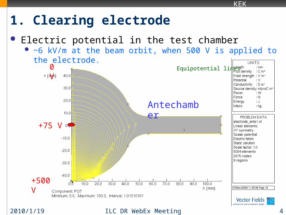
1. Clearing electrode Electric potential in the test chamber
~6 kV/m at the beam orbit, when 500 V is applied to the electrode.
2010/1/19 4ILC DR WebEx Meeting
+500 V
+75 V
0 V Equipotential lines
Antechamber

KEK
1. Clearing electrode Major results:
Reduction in electron density by a factor of 2 was observed again. Effective for other bunch spacings (4 ~ 16 ns).
However, the reduction seems less than the case of the previous test chamber. Need further investigation (simulation?).
Temperature behind the electrode was measured. Estimated input power was ~40 W/m, which is a reasonable value.
No heating at feed through. No degradation in the electrical insulation up to + 1 kV.
Visually check (2010/1/19); after one month operation No crack nor peeling was found. No problem from a functional
standpoint. But stain-like color change was observed. Stain during cleaning
procedure was visually enhanced by electron bombardment? Require further monitoring.
2010/1/19 5ILC DR WebEx Meeting

KEK
1. Clearing electrode R&D Plans ( Beam test: April ~ June)
Continue the experiment for more 3 months with beams. Measurement of electron density at a weak B field (~150 G)
Using solenoids in handCheck the dependence of electron density on B
More detailed evaluation of impedance
2010/1/19 6ILC DR WebEx Meeting

KEK
2. Grooved surface Triangular grooves have been also
studied at KEK. The properties were studied in a wiggler
magnet using the same experimental setup to that of the previous clearing electrode.
B = 0.78 T Parameters of grooves
Material: Cu, Al-alloy, SS b : 20~30, Rt:0.1~0.2 mm (rectangular) d: 2.5~5 mm
2010/1/19 7ILC DR WebEx Meeting
Monitor
R47
Y. Suetsugu, H. Fukuma, M. Pivi and L. Wang, NIM-PR-A, 604 (2009) 449
B
by L. Wang et al.
Rt
d
Al+TiN
AlSS
Cu
Inside view
(Roundness)
(Depth)
Groove

KEK
2. Grooved surface Results: until September, 2009
b = 20, Rt ~0.1 mm, d = 5 mm, SS, TiN coating (SLAC) b = 20, Rt ~0.1 mm, d = 2.5 mm, SS (KEK, discharge machining)
2010/1/19 8ILC DR WebEx Meeting
Electron densities for grooves surfaces in these parameters were lower than the case of a flat TiN-coated surface by a factor of ~6.
Availability of grooves was confirmed.
A purpose of experiment in the autumn run wasto investigate applicable structures to large scale production.
(0.9~1.0 mA/bunch)

KEK
2. Grooved surface(1) If grooved blocks are welded to a beam pipe (for Cu or Al pipe),
The machining is available. (low b, small Rt) TiN coating is possible separately from beam pipes Many welding lines (distortion of chamber, risk of leak), expensive(?)
2010/1/19 9ILC DR WebEx Meeting
b = 20, Rt = 0.1 mm Al + TiN coating d = 2.5 mm
The reduction in the electron density was larger, by a factor of ~10.
~1x10¹² m-3
~1x10¹³ m-3
~1x10¹¹ m-3
~1x10¹⁰ m-3
(0.9~1.0 mA/bunch)

KEK
2. Grooved surface(1) Groove blocks are welded to a beam pipe
Example
2010/1/19 10ILC DR WebEx Meeting
断面 断面 断面 断面
Groove block
KEK
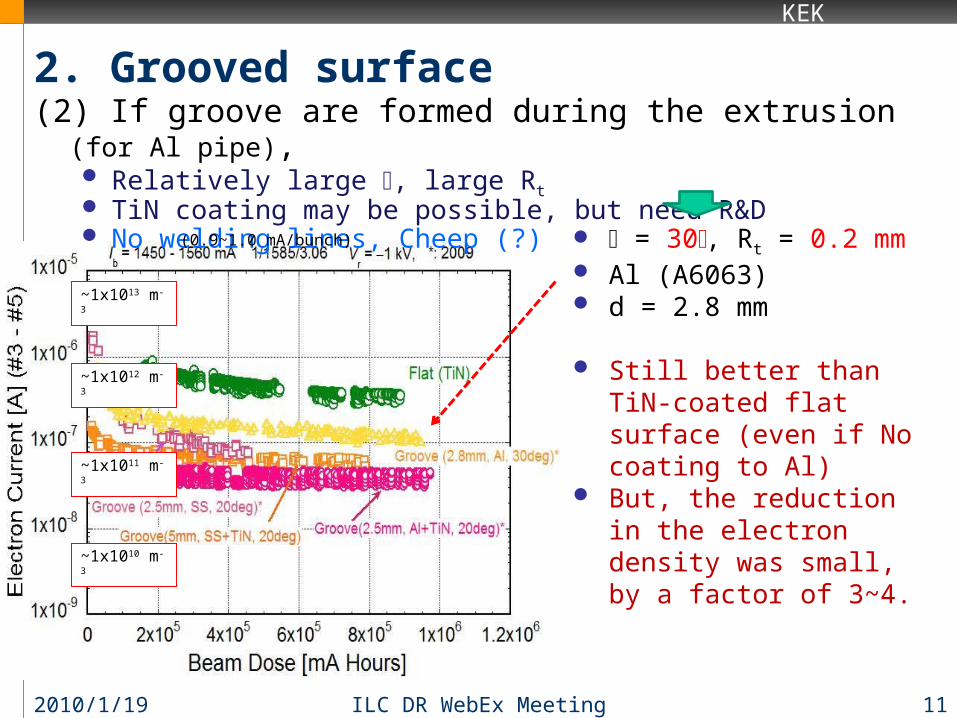
2. Grooved surface(2) If groove are formed during the extrusion (for Al pipe),
Relatively large b, large Rt TiN coating may be possible, but need R&D No welding lines, Cheep (?)
2010/1/19 11ILC DR WebEx Meeting
b = 30, Rt = 0.2 mm Al (A6063) d = 2.8 mm
Still better than TiN-coated flat surface (even if No coating to Al)
But, the reduction in the electron density was small, by a factor of 3~4.
~1x10¹² m-3
~1x10¹³ m-3
~1x10¹¹ m-3
~1x10¹⁰ m-3
(0.9~1.0 mA/bunch)

KEK
2. Plans for Super KEKB(2) Groove formed during extrusion
Example
2010/1/19 12ILC DR WebEx Meeting
Groove regionIn dipole field

KEK
3. Grooved surface R&D Plans (Beam test: April ~ June)
Manufacturing of two beam pipes with grooved surface is undergoing.Welding of groove blocks (machining is possible) [ Cu]Extrusion of Al-alloy beam pipe with grooved surface
We will find the limit of extrusion method in February.
Beam test of grooved surface with a more realistic structure.Assuming the case of Al beam pipe.
Measurement of SEY for grooved surface in Lab.No magnetic field, but we will be able to get some indication.
More detailed evaluation of impedance
2010/1/19 13ILC DR WebEx Meeting
Any suggestions on our experiments (measurement methods, shape of samples,,,) are welcome for electrodes and grooves!