Embed Size (px)
DESCRIPTION
Experimental Demonstration of a Squeezing-Enhanced Laser-Interferometric Gravitational-Wave Detector. Keisuke Goda Quantum Measurement Group, LIGO Massachusetts Institute of Technology MIT Quantum Measurement Group Christopher Wipf, Thomas Corbitt, David - PowerPoint PPT Presentation
Citation preview

1
Experimental Demonstration of a Squeezing-Experimental Demonstration of a Squeezing-Enhanced Laser-Interferometric Gravitational-Enhanced Laser-Interferometric Gravitational-
Wave DetectorWave DetectorKeisuke GodaKeisuke GodaQuantum Measurement Group, LIGOQuantum Measurement Group, LIGOMassachusetts Institute of TechnologyMassachusetts Institute of Technology
MIT Quantum Measurement GroupMIT Quantum Measurement GroupChristopher Wipf, Thomas Corbitt, DavidChristopher Wipf, Thomas Corbitt, DavidOttaway, Stan Whitcomb, Nergis MavalvalaOttaway, Stan Whitcomb, Nergis Mavalvala
CollaboratorsCollaborators Osamu Miyakawa, Alan WeinsteinOsamu Miyakawa, Alan Weinstein
California Institute of TechnologyCalifornia Institute of Technology Eugeniy Mikhailov Eugeniy Mikhailov
The College of William and MaryThe College of William and Mary Shailendhar Saraf Shailendhar Saraf
Rochester Institute of TechnologyRochester Institute of Technology Kirk McKenzie, Ping Koy Lam, Malcolm Gray, David Kirk McKenzie, Ping Koy Lam, Malcolm Gray, David
McClelland McClelland Australian National UniversityAustralian National University
LSC MeetingLSC MeetingMarch 22March 22, 2007, 2007
LIGO Lab @ MITLIGO Lab @ MIT

2
OutlineOutline
Motivation and GoalMotivation and Goal Squeezing Project at 40mSqueezing Project at 40m Experimental ApparatusExperimental Apparatus ResultsResults Summary and Future Summary and Future WorkWork
3
Quantum-Noise-Limited Quantum-Noise-Limited DetectorsDetectors
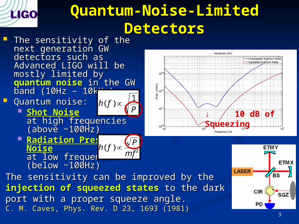
The sensitivity of the next The sensitivity of the next generation GW detectors generation GW detectors such as Advanced LIGO will such as Advanced LIGO will be mostly limited by be mostly limited by quantum noisequantum noise in the GW in the GW band (10Hz – 10kHz).band (10Hz – 10kHz).
Quantum noise:Quantum noise: Shot NoiseShot Noise
at high frequencies at high frequencies (above ~100Hz)(above ~100Hz)
Radiation Pressure Radiation Pressure NoiseNoise at low frequencies at low frequencies (below ~100Hz)(below ~100Hz)
Pfh
1)(
2)(mf
Pfh
The sensitivity can be improved by the The sensitivity can be improved by the injection of squeezed statesinjection of squeezed states to the dark port to the dark port with a proper squeeze angle.with a proper squeeze angle.C. M. Caves, Phys. Rev. D 23, 1693 (1981)C. M. Caves, Phys. Rev. D 23, 1693 (1981)
Radiation
Pressure
Noise
Shot Noise
↓ 10 dB of Squeezing

4
Squeezing-Enhanced Table-Top Squeezing-Enhanced Table-Top InterferometersInterferometers
1. Squeezing-Enhanced Mach-Zehnder Interferometer M. Xiao, L-A Wu, and H. J. Kimble, Phys. Rev. Lett. 59, 278 (1987) First demonstration of squeezing-enhanced
interferometry
2. Power-Recycled Michelson InterferometerK. McKenzie, B.C. Buchler, D.A. Shaddock, P.K. Lam, and D.E. McClelland, Phys. Rev. Lett. 88, 231102 (2002) Demonstrated squeezing-enhancement
at MHz and an increase in S/N Used squeezed light
3. Dual-Recycled Michelson InterferometerH. Vahlbruch, S. Chelkowski, B. Hage, A. Franzen, K. Danzmann, and R. Schnabel, Phys. Rev. Lett. 95, 211102 (2005) Demonstrated squeezing-enhancement
at MHz and an increase in S/N Implemented a filter cavity that rotates
the squeeze angle at MHz Used squeezed light

5
ULTIMATE GOALULTIMATE GOALImplementation of Implementation of Squeezing-EnhancementSqueezing-Enhancement in Laser-Interferometric Gravitational-Wave in Laser-Interferometric Gravitational-Wave Detectors in the Advanced LIGO ConfigurationDetectors in the Advanced LIGO Configuration
IMMEDIATE GOALIMMEDIATE GOAL Demonstration of the technology necessary to Demonstration of the technology necessary to reach the ultimate goalreach the ultimate goal
↓ ↓ ↓ ↓ ↓ ↓Squeezing Project @ Caltech 40m LabSqueezing Project @ Caltech 40m Lab Proposed a few years agoProposed a few years ago Started a year agoStarted a year ago Initially without the output mode cleaner (OMC)Initially without the output mode cleaner (OMC) People involved: People involved:
K. Goda, O. Miyakawa, E. E. Mikhailov, S. Saraf, A. Weinstein, and N. K. Goda, O. Miyakawa, E. E. Mikhailov, S. Saraf, A. Weinstein, and N. MavalvalaMavalvala

6
40m Interferometer & Squeezer 40m Interferometer & Squeezer InterfaceInterface
PSL: pre-stabilized PSL: pre-stabilized laserlaser
MC: mode-cleanerMC: mode-cleaner IFO: interferometerIFO: interferometer SQZ: squeezerSQZ: squeezer
PRM: power-recycling mirrorPRM: power-recycling mirror SRM: signal-recycling mirrorSRM: signal-recycling mirror SHG: second-harmonic generatorSHG: second-harmonic generator OPO: optical parametric oscillatorOPO: optical parametric oscillator

7
Second-Harmonic Generator Second-Harmonic Generator (SHG)(SHG)

8
Second-Harmonic Generator Second-Harmonic Generator (SHG)(SHG)
The SHG is a cavity The SHG is a cavity composed of a composed of a 5%MgO:LiNbO3 5%MgO:LiNbO3 hemilithic crystal with hemilithic crystal with ROC = 8mm and an ROC = 8mm and an output coupling mirror output coupling mirror with ROC = 50mm.with ROC = 50mm.
Crystal dimensions:Crystal dimensions:5mm x 2.5mm x 7.5mm 5mm x 2.5mm x 7.5mm
The crystal is maintained The crystal is maintained at 114 deg C for phase-at 114 deg C for phase-matching by temperature matching by temperature control.control.
Uses type I phase-Uses type I phase-matching in which the matching in which the pump and SHG fields are pump and SHG fields are orthogonally polarized orthogonally polarized (S at 1064nm, P at (S at 1064nm, P at 532nm)532nm)
The SHG conversion The SHG conversion efficiency = 30%efficiency = 30%
PD
5%MgO:LiNbO3
95% at 1064nm4% at 532nm
99.95% at both 1064nm and 532nm
Dichroic Beamsplitter
Role:Role: to generate a second-harmonic field to pump the OPO cavity to generate a second-harmonic field to pump the OPO cavity

9
Squeezer/Optical Parametric Squeezer/Optical Parametric Oscillator (OPO)Oscillator (OPO)

10
Squeezer/Optical Parametric Squeezer/Optical Parametric Oscillator (OPO)Oscillator (OPO)
The OPO is a 2.2 cm long cavity composed of a The OPO is a 2.2 cm long cavity composed of a periodically poled periodically poled KTP (PPKTP)KTP (PPKTP) crystal with flat/flat AR/AR surfaces and two crystal with flat/flat AR/AR surfaces and two coupling mirrors (Rcoupling mirrors (Rinin = 99.95% and R = 99.95% and Routout = 92%/4% at = 92%/4% at 1064/532nm).1064/532nm).
PPKTPPPKTP offers the following offers the following advantagesadvantages over LiNbO over LiNbO33
Higher nonlinearity: d = 10.8 pm/VHigher nonlinearity: d = 10.8 pm/V Higher laser damage thresholdHigher laser damage threshold Higher resistance to photorefractive damageHigher resistance to photorefractive damage Lower susceptibility to thermal lensingLower susceptibility to thermal lensing
Input Coupler
Output Coupler
PPKTP
Role:Role: to generate a squeezed vacuum field by to generate a squeezed vacuum field by correlating the upper and lower quantum correlating the upper and lower quantum sidebands around the carrier frequency sidebands around the carrier frequency
11
Monitor Homodyne Detector before Monitor Homodyne Detector before InjectionInjection

12
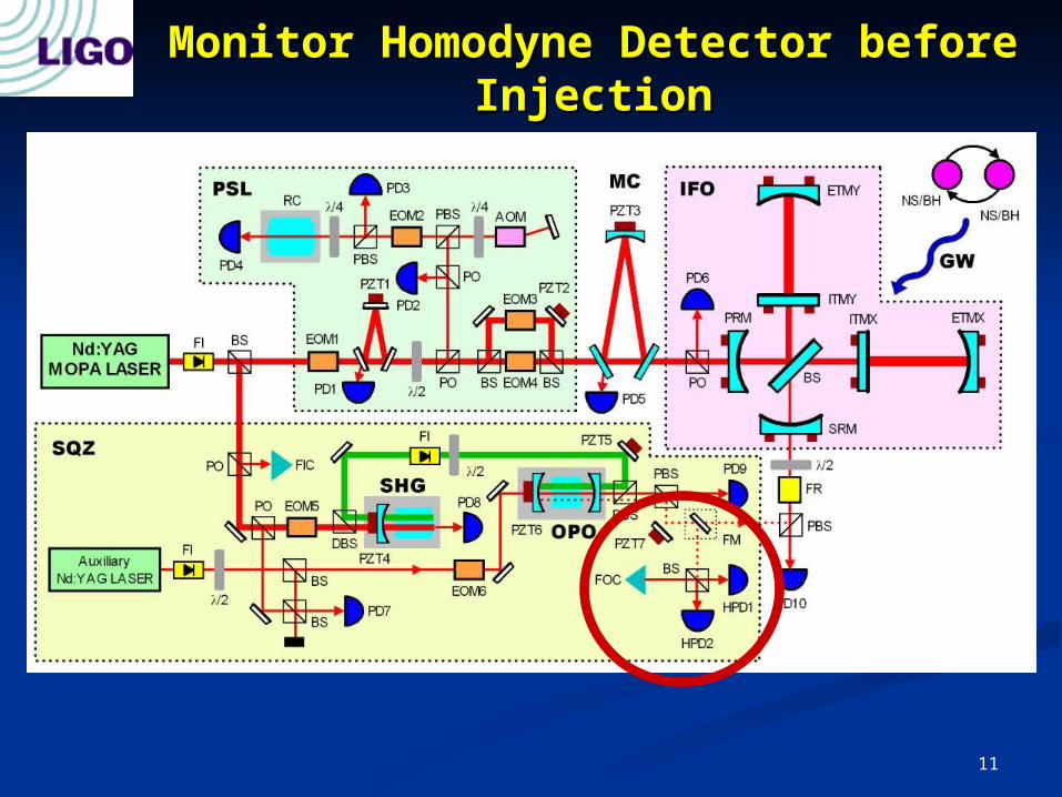
Monitor Homodyne Detector before Monitor Homodyne Detector before InjectionInjection
Homodyne detectorHomodyne detector to to measure squeezingmeasure squeezing Composed of a 50/50 BS Composed of a 50/50 BS
and a pair of home-made and a pair of home-made low-noise transimpedance low-noise transimpedance photodetectors with high photodetectors with high quantum efficiency quantum efficiency photodiodes (JDS Uniphase photodiodes (JDS Uniphase ETX500T with QE = 93%)ETX500T with QE = 93%)
The difference The difference photocurrent is measured photocurrent is measured to to subtract uncorrelatedsubtract uncorrelated noise and noise and extract extract correlatedcorrelated noise noise
And then sent to a And then sent to a spectrum analyzer to spectrum analyzer to observe the effect of observe the effect of squeezing on the squeezing on the local local oscillatoroscillator (LO) (LO) LO as a trigger to observe either squeezed or anti-squeezed quadrature LO as a trigger to observe either squeezed or anti-squeezed quadrature
variancevariance Mode-cleaning fiberMode-cleaning fiber to mode-match the LO to the squeezed vacuum to mode-match the LO to the squeezed vacuum When the When the flipper mirrorflipper mirror is up, the squeezed vacuum is monitored by the is up, the squeezed vacuum is monitored by the
homodyne detector. When the flipper is down, the squeezed vacuum is homodyne detector. When the flipper is down, the squeezed vacuum is injected into the interferometer. injected into the interferometer.
Homodyne visibility of 99% achievedHomodyne visibility of 99% achieved
Role:Role: to measure squeezing before injection to the to measure squeezing before injection to the interferometer interferometer

13
Squeezing from the OPO with Squeezing from the OPO with PPKTP PPKTP
Measured by the squeezing Measured by the squeezing monitor homodyne detectormonitor homodyne detector About About 6.5 dB6.5 dB of scanned squeezing at MHz of scanned squeezing at MHz About About 4.0 dB4.0 dB of phase-locked squeezing at frequencies down to a few kHz of phase-locked squeezing at frequencies down to a few kHz
TheThe squeeze angle squeeze angle is locked by the noise locking technique.is locked by the noise locking technique. More than 15dB of squeezing is created by the OPO, but losses kill most of it. More than 15dB of squeezing is created by the OPO, but losses kill most of it.
(a) Shot noise(a) Shot noise(b) Squeezed shot noise(b) Squeezed shot noise

14
InterferometerInterferometer
15
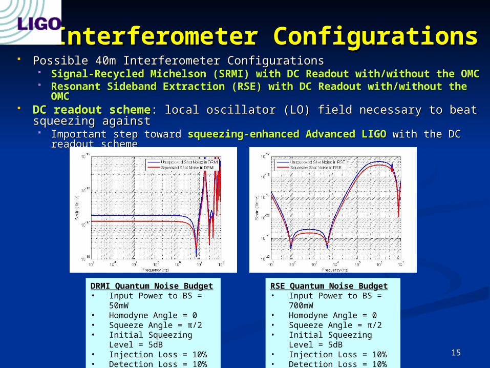
Interferometer ConfigurationsInterferometer Configurations Possible 40m Interferometer Configurations Possible 40m Interferometer Configurations
Signal-Recycled Michelson (SRMI) with DC Readout with/without the OMCSignal-Recycled Michelson (SRMI) with DC Readout with/without the OMC Resonant Sideband Extraction (RSE) with DC Readout with/without the Resonant Sideband Extraction (RSE) with DC Readout with/without the
OMCOMC DC readout schemeDC readout scheme: local oscillator (LO) field necessary to beat squeezing : local oscillator (LO) field necessary to beat squeezing
againstagainst Important step toward Important step toward squeezing-enhanced Advanced LIGOsqueezing-enhanced Advanced LIGO with the DC readout with the DC readout
schemescheme
DRMI Quantum Noise Budget
• Input Power to BS = 50mW
• Homodyne Angle = 0• Squeeze Angle = π/2• Initial Squeezing Level =
5dB• Injection Loss = 10%• Detection Loss = 10%
RSE Quantum Noise Budget
• Input Power to BS = 700mW
• Homodyne Angle = 0• Squeeze Angle = π/2• Initial Squeezing Level =
5dB• Injection Loss = 10%• Detection Loss = 10%
16
SRMI Noise FloorSRMI Noise Floor
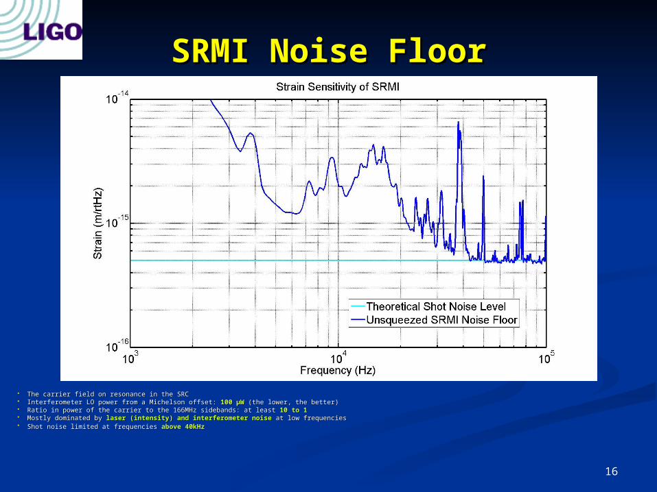
The carrier field on resonance in the SRCThe carrier field on resonance in the SRC Interferometer LO power from a Michelson offset: Interferometer LO power from a Michelson offset: 100 100 μμWW (the lower, the better) (the lower, the better) Ratio in power of the carrier to the 166MHz sidebands: at least Ratio in power of the carrier to the 166MHz sidebands: at least 10 to 110 to 1 Mostly dominated by Mostly dominated by laser (intensity) and interferometer noiselaser (intensity) and interferometer noise at low frequencies at low frequencies Shot noise limited at frequencies Shot noise limited at frequencies above 40kHzabove 40kHz

17
Verification of Shot NoiseVerification of Shot Noise
Noise increase by Noise increase by 3dB3dB at frequencies above 40kHz at frequencies above 40kHz »» Shot NoiseShot Noise Noise increase by Noise increase by 6dB6dB at frequencies below 10kHz at frequencies below 10kHz »» Laser (Intensity) NoiseLaser (Intensity) Noise Noise increase in between 10kHz and 40kHz Noise increase in between 10kHz and 40kHz »» Interferometer NoiseInterferometer Noise

18
Injection and Detection of Injection and Detection of SqueezingSqueezing

19
Mode-matching and alignmentMode-matching and alignment of squeezed vacuum of squeezed vacuum to the interferometer are done by a mode-matching to the interferometer are done by a mode-matching telescope and steering mirrors.telescope and steering mirrors.
Isolation of the squeezing-enhanced Isolation of the squeezing-enhanced interferometer field interferometer field from the injection of squeezing is from the injection of squeezing is done by Faraday isolation. done by Faraday isolation.
An extra Faraday isolatorAn extra Faraday isolator is installed to further reject is installed to further reject the LO light from going into the OPO. the LO light from going into the OPO.
Detection of the squeezing-enhanced interferometer Detection of the squeezing-enhanced interferometer field is done by a high transimpedance amplifier with a field is done by a high transimpedance amplifier with a high quantum efficiency photodiode (JDS Uniphase high quantum efficiency photodiode (JDS Uniphase ETX500T with QE: 93%)ETX500T with QE: 93%)
Injection and Detection of Injection and Detection of SqueezingSqueezing

20
ResultsResults

21
SRMI Noise FloorSRMI Noise Floor
The carrier field on resonance in the SRCThe carrier field on resonance in the SRC Interferometer LO power from a Michelson offset: Interferometer LO power from a Michelson offset: 100 100 μμWW (the lower, the better) (the lower, the better) Ratio in power of the carrier to the 166MHz sidebands: at least Ratio in power of the carrier to the 166MHz sidebands: at least 10 to 110 to 1 Mostly dominated by Mostly dominated by laser (intensity) and interferometer noiselaser (intensity) and interferometer noise at low frequencies at low frequencies Shot noise limited at frequencies Shot noise limited at frequencies above 40kHzabove 40kHz
22
Squeezing-Enhanced SRMISqueezing-Enhanced SRMI
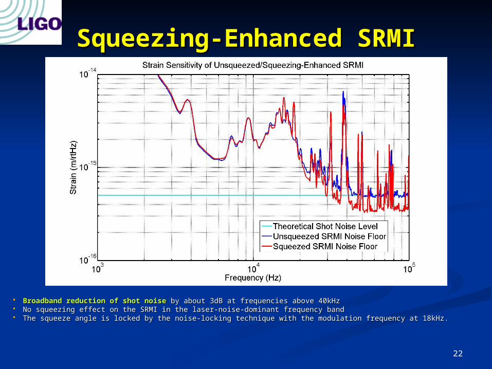
Broadband reduction of shot noiseBroadband reduction of shot noise by about 3dB at frequencies above 40kHz by about 3dB at frequencies above 40kHz No squeezing effect on the SRMI in the laser-noise-dominant frequency bandNo squeezing effect on the SRMI in the laser-noise-dominant frequency band The squeeze angle is locked by the noise-locking technique with the modulation frequency at 18kHz.The squeeze angle is locked by the noise-locking technique with the modulation frequency at 18kHz.

23
Increase in S/N by SqueezingIncrease in S/N by Squeezing
Simulated GW SignalSimulated GW Signal: Excitation of BS at : Excitation of BS at 50kHz50kHz The noisy peaks in the squeezing spectrum are due to the The noisy peaks in the squeezing spectrum are due to the optical crosstalkoptical crosstalk between the interferometer and OPO between the interferometer and OPO
(imperfect isolation of the interferometer LO field from going into the OPO in spite of two Faraday isolators). (imperfect isolation of the interferometer LO field from going into the OPO in spite of two Faraday isolators).

24
Summary and Future Summary and Future WorkWork SUMMARYSUMMARY
We are developing We are developing techniquestechniques necessary for squeezing-enhanced necessary for squeezing-enhanced laser-interferometric GW detectors laser-interferometric GW detectors
GW detector-compatible squeezerGW detector-compatible squeezer Squeezing injection schemeSqueezing injection scheme Squeeze angle locking schemeSqueeze angle locking scheme Interferometer locking scheme with squeezingInterferometer locking scheme with squeezing
With these techniques, we have demonstrated With these techniques, we have demonstrated squeezing-squeezing-enhancementenhancement ( (an increase in S/Nan increase in S/N) in the LIGO prototype ) in the LIGO prototype interferometer by about 3dB in the shot-noise-limited frequency interferometer by about 3dB in the shot-noise-limited frequency band (above 40kHz) band (above 40kHz)
This squeezer is applicable to This squeezer is applicable to anyany interferometer configuration interferometer configuration with DC readout. with DC readout.
FUTURE WORKFUTURE WORK Squeezing-enhanced RSE (full Advanced LIGO configuration)Squeezing-enhanced RSE (full Advanced LIGO configuration) Squeezing with the OMCSqueezing with the OMC Coherent control of squeezingCoherent control of squeezing Doubly-resonant OPO in a ring cavity Doubly-resonant OPO in a ring cavity Noise-hunting for squeezing-enhanced interferometry in the GW Noise-hunting for squeezing-enhanced interferometry in the GW
bandband Installation into Enhanced LIGO and then Advanced LIGO?Installation into Enhanced LIGO and then Advanced LIGO?

25
AcknowledgementsAcknowledgements
We thank Caltech 40m Lab and MIT We thank Caltech 40m Lab and MIT Quantum Measurement Group for Quantum Measurement Group for invaluable support for the experimentinvaluable support for the experiment
We also thank ANU for providing high We also thank ANU for providing high quantum efficiency photodiodesquantum efficiency photodiodes
We gratefully acknowledge support We gratefully acknowledge support from NSFfrom NSF