Embed Size (px)
Citation preview

CONTROL KEYBOARD
USER MANUAL
ACC-KB003BK Keyboard Manual
ContentsPart One: Attention………………………………………………………………………………………………………....…2Part Two: Brief Introduction……………………………………….…………………………………………………………2 1. Brief Introduction…………………………………………………………………………………..………………………2 2. Button Functionality……………………………………………………………………………………………………….2Part Three: Keyboard Connection………………………………………………………………………………………….5 1. Connection Diagram of Multiple Keyboards with PTZ Dome……………………………………………5
2. Connection Diagram of Keyboard, Matrix Switch, and PTZ Dome System……………………….6 3. Connection Diagram of Multiple Keyboards, DVRs, and PTZ dome System…………………….7Part Four: PTZ Dome Mode…………………………………………….…………….……………………………………8 1. Enter PTZ Dome Mode…………………………………………………………………………………………………8 2. Select the Address of PTZ Dome You Want to Control:…………………………………………………8 3. Controlling the PTZ Dome…………………………………………………………………………………………….8Part Five: Controlling the Matrix Switching System………………………………………………………….…9 1. Matrix Switch Mode of the Keyboard……………………………………………………………………………9 2. The Keyboard Operation Lock……………………………………………………………………………………….9 3. Unlock Keyboard Operation…………………………………………………………………………………………….9 4. Keyboard Password Setup……………………………………………………………………………………………10 5. Select Monitor……………………………………………………………………………………………………………….10 6. Select Camera…………………………………………………………………………………….…………………………10 7. Controlling the PTZ Dome………………………………………………………………………………………………10 8. Auxiliary Functions…………………………………………………………..…………………………………………..11 9. Auto Sequencing……………………………………………………………….………………………………………..12 10. System Program Switch……………………………………………….………………………………………………12 11. System Synchronous Switching…………………………………………………………..…………………….13 12. System Group Switch……………………………………………………..………………………………………14 13. Alarm Linkage………………………………………………………………………………………………………………15 14. Defense Police Point………………………………….……………………………………………………………..15 15. Police Point State Diagnostic………………………………………………………….………………………….15 16. Sound Switch………………………………………………………………………………….……………………………15 17. Menu Button Operation Instructions…………………………………………………………………………..15Part Six: Controlling the DVR / Image Processor…………………………………………………………………15 1. Enter the DVR /Image Processor Mode………………………………………………………………..………15 2. Exit the DVR /Image Processor Mode…………………………………………………………………..………15 3. Select the DVR / Image Processor………………………………………………………….…………………….16 4. Controlling DVR & Image Processor…………………………………………………….………………………16 Control Keyboard…………………………………………………………………………….…………………………………17 Declaration…………………………………………………………………………………………………………………………18 FCC Statement……………………………………………………………………………………………………………………19
1

ACC-KB003BK Keyboard Manual
Part One: Attention1. Be careful when transporting the device.
Damages caused by stress, vibration, and moisture should be avoided during the
transportation and storage process. Any damage due to improper transport or storage is not
covered under warranty.
2. If the device stops functioning.
If there is any odor coming from the device, or if the device emits any smoke, please unplug
the device and contact the manufacturer or dealer.
3. Do not take the equipment apart or refit its structure.
Do not open the device housing, as this can cause permanent damage. If the device stops
operating correctly, please contact the manufacturer or dealer.
4. Do not store other items on top of the device.
Make sure that there are no flammable or metal objects which will cause fire, short circuit,
or damage near the device. If water or moisture penetrates the device, please power off the
device and allow to fully dry for 24 hours before attempting to power back on.
5. Avoid impact and vibration.
Protect the device from strong impact and vibration when using or transporting the device.
6. Avoid electric fields and magnetic fields.
The keyboard operation may be influenced by electromagnetic field when the equipment is
near a TV, transmitter, electromagnetic equipment, electric motor, or loudspeaker.
7. Avoid humidity, dust, & extreme temperatures.
To avoid damage and excessive wear, please do not leave the device in environments with
humidity, dust, or extreme hot or cold temperatures.
8. Cleaning the device.
In order to clean the device, soak a soft washcloth with detergent solution and wring out the
water. Wipe down the device using the damp cloth. Do not use gasoline, paint thinner or
other harsh chemicals to clean the housing of the device.
Part Two: Brief Introduction
1. Brief Introduction:The ACC-KB003BK Keyboard functions by combining a matrix switching system with a
DVR & PTZ dome camera. It can program a matrix switching system, DVR, PTZ dome, and decoder. The LED screen of the keyboard has the ability to display the quantity and operating status of monitors, cameras, and DVRs.
2. Button Functionality:
MON— Select a monitor
CAM— Select a camera
LAST— Auto Switch of Reverse Running
NEXT— Auto Switch of Positive Direction Running
RUN— Auto Switch of Operation
2

ACC-KB003BK Keyboard Manual
TIME—Dwell Time Transition
SALVO—Sync Transition
HOLD—Save the Image
ON— Lunch the Functions
OFF— Close the Functions
PATRN—Auxiliary Functions
SHOT— Call Presets
ARM—Set Alarm Touch Spot
F1— Select Network Matrix
ACK— Function Confirmation
F2— Soft Lock
PROG— Program Matrix Menu
CLEAR—Clear Digit
CLOSE—Close the Lens Iris
OPEN— Open the Lens Iris
FAR— Adjust the Focus
NEAR— Adjust the Focus
TELE—Get Close-up Image (ZOOM-)
WIDE— Get Panorama Image (ZOOM+)
Direction Block—Control the PTZ to up, down, left and right direction.
Digit Block —digit input.
Note: Pressing the” 0” key for a moment will revert the digit to zero. When the number of digit exceeds four digits, the digit shown on the keyboard will auto revert to zero and reshow the new numbers typed in.
There are three operating modes for the keyboard including matrix mode, PTZ dome mode, and DVR mode.
After plugging in the 9-12V DC power supply and powering on the device with either a matrix switch or a PTZ dome camera connected, the interface will display the address, protocol, and baud rate. The address corresponds to the Matrix mode, the protocol & baud rate correspond to the PTZ dome and the DVR. At this time you can choose the corresponding keyboard address, protocol, and baud rate through the joystick. Press the” ON” key to confirm.
If the keyboard is directly connected with a matrix (the baud rate which is set when power on the device should be 9600), the keyboard will automatically enter matrix mode, and cannot transit to PTZ dome mode and DVR mode by pressing the “F2” Key.
If the keyboard is connected to a non-matrix terminal, the keyboard will first enter PTZ dome mode, and “PTZ” will be shown on the left bottom of the LCD screen. Pressing the “F2” key will switch the keyboard to matrix mode, DVR mode, or PTZ dome mode. When the keyboard is in DVR mode, the left bottom corner of the LCD screen will display “DVR.”
3

ACC-KB003BK Keyboard Manual
Part Three: Keyboard Connection
4

ACC-KB003BK Keyboard Manual
1. Connection Diagram of Multiple Keyboards with PTZ Dome
Note: One PTZ Dome can connect with multiple keyboards, but the addresses of keyboards cannot be the same.
5

ACC-KB003BK Keyboard Manual
2. Connection Diagram of Keyboard, Matrix Switch, and PTZ Dome System
Note: When entering into matrix mode, the baud rate should be set as 9600, you can select in the system menu to control the protocol, baud rate, and address of the PTZ dome.One PTZ Dome can connect with multiple keyboards, but the addresses of keyboards cannot be the same.
6
Matrix Switch System
Keyboards Connecting to Matrix System

ACC-KB003BK Keyboard Manual
3. Connection Diagram of Multiple Keyboards, DVRs, and PTZ dome System
Note: One PTZ Dome can connect with multiple keyboards, but the addresses of keyboards cannot be the same.
Part Four: PTZ Dome Mode
1. Enter PTZ Dome Mode:
Before powering on the keyboard, connect the keyboard signal cable with a PTZ dome
7
Keyboards Connected to DVRs

ACC-KB003BK Keyboard Manual
communication cable. Power on the keyboard, set protocol and baud rate in the menu of
the keyboard the same as that of PTZ dome. The keyboard will automatically enter PTZ
dome mode, the left bottom of LCD screen will show “PTZ”. You may now control the PTZ
dome and PTZ.
2. Select the Address of PTZ Dome You Want to Control:
To control the PTZ dome set to address ”1” type Number “1” then press “CAM”.
To control a different camera which is not set to address “1” type the number that
corresponds to that camera’s address then press “CAM”.
The address number can be selected between 1-255.
The CAM area of the LCD screen will display the corresponding PTZ dome address number.
3. Controlling the PTZ Dome:
3.1 Horizontal and Vertical Movement at Variable Speed:
The deviation degree of the joystick is proportional to the speed of PTZ dome, the
farther away the joystick deviates from the center, the higher the speed of the PTZ dome
will be. Let go of the joystick to stop operating the PTZ dome movements.
3.2 Controlling the Zoom of the PTZ Dome:
Press “CLOSE/OPEN” to control the lens Iris.
Press “NEAR/ FAR” to adjust the focus of the image.
Press “WIDE / TELE” to zoom in or zoom out.
3.3 Setting Presets:
To set a preset, select one camera and adjust the image to your preference for the
preset. Type in the preferred preset number, and press” SHOT” then press “ON” to set
the preset. Adjust the image, and go ahead to set another preset.
3.4 Calling the presets:
To call a preset, first type in the corresponding preset number in the digit block which
you want to see. Press “SHOT” then press “ACK.” The preset image will be displayed on the
monitor. If the preset has not been set previously, then there will l be no change to the
preset image.
3.5 Clearing the presets:
8

ACC-KB003BK Keyboard Manual
To erase a preset, first type in the corresponding preset number in the digit block which
you want to erase. Press “SHOT” then press “OFF.”
3.6 Auxiliary functions:
The key “PATRN +ON / OFF” is to control the auxiliary functions, the detailed
functions and numbers are as follows:
0 + PATRN + ON / OFF Enable/Disable auto running of the PTZ dome
1 + PATRN + ON / OFF Enable/Disable auxiliary function #1 of PTZ dome
2 + PATRN + ON / OFF Enable/Disable auxiliary function #2 of PTZ dome
3+PATRN+ON/OFF Enable/Disable auxiliary lamplight of decoder
4 + PATRN + ON / OFF Enable/Disable auxiliary windshield wiper of the PTZ dome
If the PTZ dome camera(s) have auxiliary functions such as windshield wipers, lamplights,
and auto running, the keyboard can be mapped to operate these functions
Steps:
A) Call the controlled camera to monitor
B) Type in auxiliary function number (1-4).
C) Press “PATRN”
D) Press “ON” or “OFF” to open or close the functions.
Part Five: Control the Matrix Switch System
1.Matrix Switch Mode of the Keyboard When the communication cable of the keyboard is connected to a matrix switch, the
baud rate must be 9600 when powered-on. The indicator light (CODE) will blink when a
matrix switch is connected correctly to the keyboard. The status display area shows “Lock”
which indicates that a 4 digit password is required. (The initial password is “0000”) The
password input method is: F2 +“****”+ OFF.
If the password is typed in correctly, the status will be displayed as “----”. Type in one
monitor number and press “MON” to confirm, the monitor display area will show the
current controlled monitor number, which means the keyboard is under matrix work mode.
9

ACC-KB003BK Keyboard Manual
2.The Keyboard Operation Lock:
After completing the keyboard operation, you have the option to lock the keyboard to
prevent unwanted tampering by other parties:
1. Press “F2”
2. Press “ON” The keyboard is now in “LOCK” mode.
2.1 Call up the main menu of high speed dome: Press“65” + “SHOT” + “ACK” to call up the main menu, you may set the menu items there. More details please refer to high speed dome test guidelines.
3.Unlock the Keyboard Operation:
To remove the keyboard lock, complete the following button sequence:
Press F2, (Enter the 4 digit password), OFF
(The initial default password is”0000”)
4. Keyboard Password Setup:
The keyboard password is limited to 4 digits, if you need to change the keyboard
password, complete the following steps:
1. Press ”F2”
2. Type in 4-digit password“****”
3. Press key ” ACK ”
Note: If you forget the password, you can retrieve the password at the “KEYBOARD
PASSWORD” in the menu function of the matrix switching host.
5. Select Monitor:
To efficiently connect the keyboard to a matrix host, first select a monitor then call a
camera to operate on the cameras:
10

ACC-KB003BK Keyboard Manual
1. In the digit block, type in a valid monitor number you want to call
2. Press “MON”, the monitor display area will show the new typed in monitor
number.
For example, to call number 2 monitor the user would press “2” then “MON”
6. Select Cameras:
In the digit block, type in camera number you want to call. This camera number should have
video signal to input.
Press “CAM”. The image of the selected camera should now appear on the selected monitor,
and the camera display area will display the newly typed in camera number.
For example, in order to call camera #1 to display on monitor #2:
1. Press “2”
2. Press “MON”
3. Press “1”
4. Press “CAM”
7. Controlling the PTZ Dome:
To control a PTZ dome camera under matrix mode, you need to unplug the RS485 bus
from port “CODE2” of the matrix switch. Next, either connect the RS485 bus to the PTZ
control cable or connect the PTZ dome using a decoder. Make sure to connect the positive
and negative polarity correctly.
Set the protocol, address, and baud rate of the PTZ dome:
Press “PROG” (Enter main system) + “1”button to choose “system” menu(参考中文:+“1”键(选择“系统”菜单)+ “1”(select menu of “system”) + “3” (select menu of “PTZ select”) + joy stick control (configure protocol and baud
rate) + digit(save the number setting)+ “CLEAR”(Back to the main menu)
Press “4” Select “PTZ ID Select” Menu + digit (set the address) + “PROG” (exit)
The parameters on the menu refer to the parameter displayed on the monitor after the
PTZ dome initializes.
Note: After setting the protocol (joystick up and down) and baud rate ( joystick left
and right) in the “ PTZ select” menu, you should save the configuration by pressing
the digit key of the setting items to continue normal operation.
7.1 Horizontal and Vertical Movement at Variable Speed:
The deviation degree of the joystick is proportional to the speed of PTZ dome, the farther
11

ACC-KB003BK Keyboard Manual
away the joystick deviates from the center, the higher the speed of the PTZ dome will be.
Let go of the joystick to stop operating the PTZ dome movements.
7.2 Controlling the Lens:
Press “NEAR/ FAR” to adjust the Lens focus.
Press “WIDE / TELE” to zoom in or zoom out.
7.3 Set Presets:
Select one camera, adjust the image to the intended position of the preset, type in the
preset number, then press “SHOT”
Press “ON” adjust the images, then go to set the next preset
7.4 Call the presets:
To call the controlled camera to the controlled monitor, first type in the corresponding
preset number in the digit block which you want to view. Press “SHOT” then “ACK”, the
preset image will be displayed on the monitor. If the preset hasn’t been set previously,
then there will l be no change to the preset image.
7.5 Clear the presets:
Select cameras, type in the preset number, press ” SHOT”, then press” OFF”.
8. Auxiliary Functions:
The key “PATRN +ON / OFF” is to control the auxiliary functions, the detailed
functions and numbers are as follows:
1 + PATRN + ON / OFF Enable/Disable auxiliary function #1 of the decoder
2 + PATRN + ON / OFF Enable/Disable auxiliary function #2 of the decoder
3 + PATRN + ON / OFF Enable/Disable auxiliary lamplight of the decoder
4 + PATRN + ON / OFF Enable/Disable auxiliary windshield wiper of the decoder
If the decoder has auxiliary functions such as windshield wipers, lamplights, and auto
running, the keyboard can be mapped to operate these functions.
Steps:
1) Call the controlled camera to monitor
2) Type in auxiliary function number (1-4).
3) Press “PATRN”
4) Press “ON” or “OFF” to enable or disable the functions
12

ACC-KB003BK Keyboard Manual
9. Auto Sequencing:
Auto Sequencing will display one video port at a time at a specific time interval.
9.1 Setting up Auto Sequencing :
1) Call the monitor number which you want to set
2) Type in the dwell time for every camera between 2-240 seconds
3) Type in the starting camera address in the sequence
4) Type in the ending camera address in the sequence
5) Start to run auto sequence
For example: To enable monitor #3 to switch from camera # 1 to camera # 6 with a 2
second interval, the user could complete the following steps:
“3” + “MON”. (Select monitor)
“2” + “TIME” (Set auto sequence dwell time)
“1” + “ON” (Start address of cameras)
“6” + “OFF” (Ending address of cameras)
Press 0 + RUN to run Free Switch; (参考的中文: 0 + RUN (运行自由切换))“0” + “RUN” (Auto switch of operation)
9.2 Setting the Dwell Time of Cameras:
1) From the auto sequencing queue, type in a dwell time number(2-240seconds)
2) Press “TIME”
9.3 Run auto sequence:
1) Type in digit “0”
2) Press “RUN”
9.4 Disabling Auto Sequence:
Press a number greater than “0”+ “CAM” to disable auto sequence. Press “HOLD” to
pause the sequence at the camera being viewed currently.
Press “0” + “RUN” to re-enable auto sequence.
9.5 Forward/ Backward to single step sequencing or change the sequencing direction:
Press “NEXT” to switch direction to “ascending”
Press “LAST” to switch direction to “descending”
10. System Program Switch:
System program switch will display one video port at a time at a specific time interval
using a matrix switch.
13

ACC-KB003BK Keyboard Manual
10.1 Set program switching queue:
See “TOUR” (Program Switch) setting under menu function “SWITCH”( Switch setting)
of the host. Steps are as following:
1) Press key ” PROG” to call out main system menu
2) Press key” 3” to choose switching
3) Press key”1” to choose program switch
4) Press key“0~9” to set program sequence number
5) Press key” SALVO” to call out edit menu and configure editing.
10.2 Run the Switching Queue Program:
1. On the keyboard, input the system switch serial number you want to call (1-32)
2. Press RUN
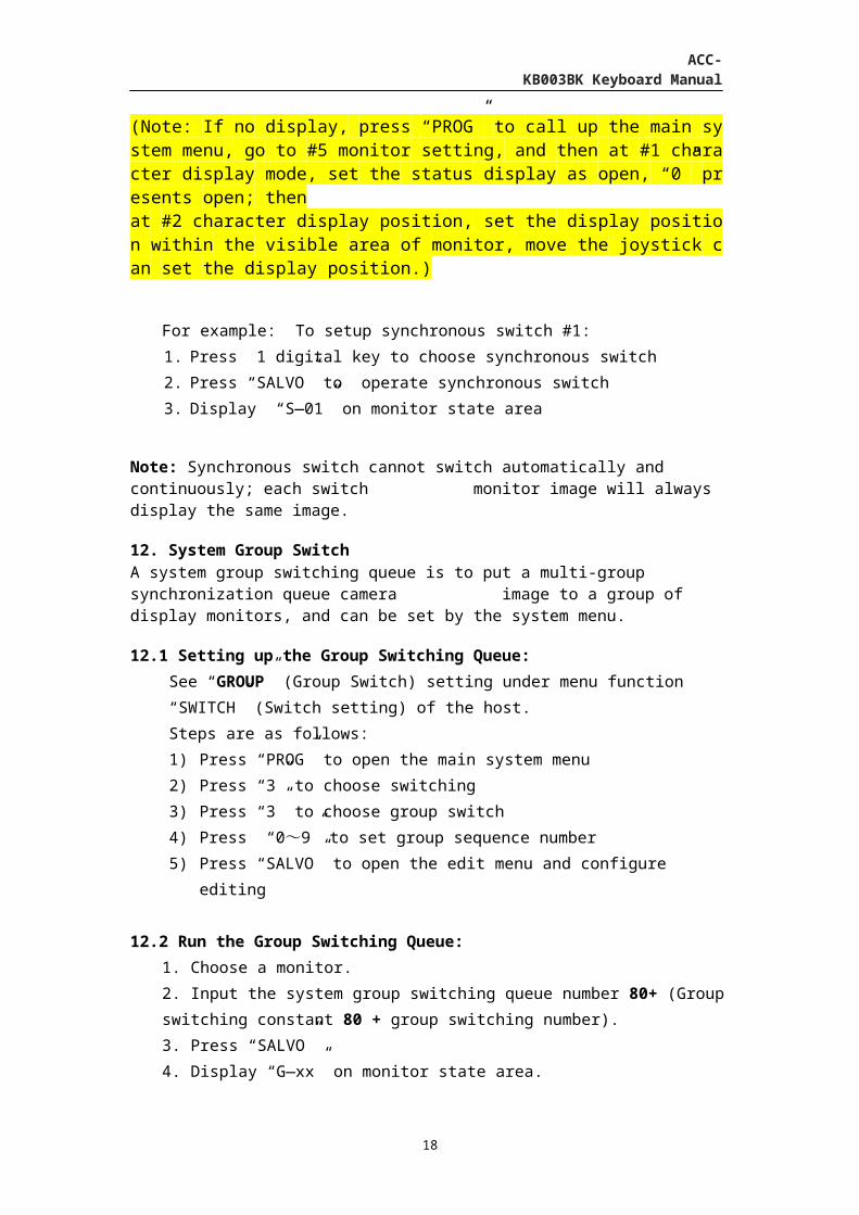
3. Display “T—xx” on the monitor state area (Note: If no display, press “PROG” to call up the main system menu, go to #5 monitor setting, and then at #1 character display mode, set the status display as open, “0” presents open; then at #2 character display position, set the display position within the visible area of monitor, move the joystick can set the display position.) For example: To run program switch #2 on Monitor #3:
1. Input number 3; press MON to confirm
2. Input number 2; press RUN to run
3. Display “T—02” on number 3 monitor state areaNote: The same program switching queue can be ran by multiple monitors at the same
time, the monitor image between each other is not affected.
10.3 Change the Program Switching Direction:
Press NEXT to enable the switching direction to ascend
Press LAST to enable the switching direction to descend
10.4 Pause the Switching Operation Program:
Press HOLD to pause the switching operation. The images will remain on the switching
camera’s picture. Pressing a digit greater than “0” +CAM makes the images remain on the
camera’s selected pictures.
11. System Synchronous Switching A system synchronous switching queue refers to a group of camera images switching to a group of monitors, which can be set in the menu.
14

ACC-KB003BK Keyboard Manual
11.1 Setting the Synchronous Switching Queue:
See “SALVOS” (Synchronous Switch) setting under menu function “SWITCH” (Switch
setting) of the host.
Steps are as follows:
1) Press “PROG” to call out main system menu
2) Press “3” to choose switching
3) Press “2” to choose synchronous switch
4) Press “0~9” to set synchronous sequence number
5) Press “SALVO” to open the edit menu and configure editing.
11.2 Run Synchronous Switching Queue:
1. Adjust the first monitor of synchronous switch monitor group as a controlled monitor. 2. Input the system synchronous switching sequence number 1-16. 3. Press SALVO, when synchronous switching queue monitor number exceed the largest monitor number, the redundant camera images will not be displayed.
4. Display “S—xx” on monitor state area (Note: If no display, press “PROG” to call up the main system menu, go to #5 monitor setting, and then at #1 character display mode, set the status display as open, “0” presents open; then at #2 character display position, set the display position within the visible area of monitor, move the joystick can set the display position.)
For example: To setup synchronous switch #1:
1. Press 1 digital key to choose synchronous switch
2. Press “SALVO” to operate synchronous switch
3. Display “S—01” on monitor state area
Note: Synchronous switch cannot switch automatically and continuously; each switch monitor image will always display the same image.
12. System Group Switch A system group switching queue is to put a multi-group synchronization queue camera image to a group of display monitors, and can be set by the system menu.
12.1 Setting up the Group Switching Queue:
See “GROUP” (Group Switch) setting under menu function “SWITCH” (Switch setting)
of the host.
Steps are as follows:
15

ACC-KB003BK Keyboard Manual
1) Press “PROG” to open the main system menu
2) Press “3” to choose switching
3) Press “3” to choose group switch
4) Press “0~9” to set group sequence number
5) Press “SALVO” to open the edit menu and configure editing
12.2 Run the Group Switching Queue:
1. Choose a monitor.
2. Input the system group switching queue number 80+ (Group switching constant 80 +
group switching number).
3. Press “SALVO”
4. Display “G—xx” on monitor state area.
(Note: If no display, press “PROG” to call up the main system menu, go to #5 monitor setting, and then at #1 character display mode, set the status display as open, “0” presents open; then at #2 character display position, set the display position within the visible area of monitor, move the joystick can set the display position.)
For example: To operate group switch #1:
1. Press “81” to choose group switch #1
2. Press “SALVO” to operate group switch #1
3. Display “G—01” on monitor state area
12.3 Disabling the Group Switch Operation:
To stop the group switch operation, input “0” then press “SALVO”
To pause the groups switch operation, press “HOLD”
13. Alarm Linkage:An alarm trigger can automatically switch video input to the video output, and may control alarm linkage.
Alarm linkage open: Input alarm touch point#, press “ARM” then press ON. Alarm linkage closed: Input alarm touch point#, press “ARM” then press OFF.
14. Defense Police Point:A built-in 16 contact interface or alarm host point can allow fortification and disarming.
Police point fortification: Input alarm touch point#, press “ARM” then press “ON”
16

ACC-KB003BK Keyboard Manual
Police point disarming: Input alarm touch point#, press “ARM” then press OFF
Police point response: Input alarm touch point#, press “ARM” then press ACK
15. Police Point State Diagnostic:
Open Police Point State Diagnostic: Input “97”, press “PATRN” then press “ON”
Close Police Point State Diagnostic: Input “97”, press “PATRN” then press “OFF”
16. Sound Switch:The audio functionality can be enabled or disabled using the keyboard.
To operate, input 99 then press “PATRN” 17. Menu Button Operation Instructions:
Press the “PROG button” to enter the matrix mainframe menu programming state, in the
menu, the operation useful buttons as follows:
Enter the submenu: press “0~9”Back to Main Menu: Press “CLEAR”Exit menu: Press “PROG” Enter programming menu: Press “SALVO”Program digits: Press “0~9”
Program baud rate: Joystick left and right.Program cursor up: Joystick Up
Program cursor down: Joystick DownProgram cursor left: Joystick Left Program cursor right: Joystick Right
Part Six: Controlling the Digital Video Recorder / Image Processor
1. Enter the Digital Video Recorder/Image Processor Mode:
When the keyboard is in non matrix mode, press the keyboard mode “F2”; When the LCD
screen sate area showing “DVR”, which means the keyboard accesses the function of digital
video recorder \ image processor. You can now control the digital video recorder and image
processor. Press the button on the keyboard to get the corresponding function as digital
video recorder and image processor panel buttons.
2. Exit the Digital Video Recorder /Image Processor Mode: Press the keyboard mode “F2”, “PTZ” will on the LCD screen, the keyboard will be back from
digital video recorder\ image processor controlling pattern, and enter in the status of
controlling the front Speed Dome Cameras \ PTZ equipment
3. Choose the Digital Video Recorder/Image Processor:Each digital video recorder\image processor has a different address number, before controlling the digital video recorder\image processor; you should input its address number. And you have to input the order “X+MON” (X is the IP address of digital video recorder\image processor) before the keyboard has entered in the “DVR” pattern. When the input finishes, then press “F2” button to enter “DVR” pattern; this moment you can control the digital video recorder\image processor whose address number is “X” via the keyboard. If you
17
ACC-KB003BK Keyboard Manual
want to control other DVR nearby, you have to press “F2” to exit “DVR” pattern, and then input the address number, steps as follows:The keyboard should be in the not ”DVR” pattern, (that means the “DVR” is not shown on the lower left corner),
Please input the number “1” and press “MON”. You can now control the digital video recorder\image processor of address number “1”.
If you input “2”, then you can control the digital video recorder\image processor at address number “2”.
The rest can be done in the same manner. After the input completes, press “F2” to enter the DVR pattern.
4. Controlling the Digital Video Recorder / Image Processor:Each key on the keyboard which is corresponding to the related function of digital video recorder/picture processor is broadly in line with the below key function instruction. Different digital video recorder or picture processor might be a little different in their specific function. The detailed operation you can refers to the instructions of digital video/image processor. Keyboard functions are as follows:
MON: Return to Monitor State
CAM: Enter the PTZ Control State
USER: Access the menu
ARM: Enter to Edit
TIME: Input Method
F1: Split Screen
LAST: Up Direction
NEXT: Right Direction/fast forward
HOLD: Down Direction
RUN: Left Direction/Fast Backward
SALVO: Power off
ACK: Auto
CLEAR: Delete / Clear
SHOT: Record
PATRN: Play
ON: confirm /Pause CONTROL KEYBOARD
The installation of this product should be performed by qualified service personnel and
should conform to all local codes.
CAUTION
RISK OF ELECTRIC SHOCK, DO NOT REMOVE COVER.
18

ACC-KB003BK Keyboard Manual
NO USER-SERVICEABLE PARTS INSIDE.
REFER SERVICING TO OUALIFIED SERVICE PERSONNEL.
WARNING
To reduce the risk of fire and shock hazard, do not expose this product to rain or moisture.
The lighting flash with arrowhead symbol within an equilateral triangle is intended to alert
the user to the presence of dangerous voltage within the product’s enclosure that may be of
sufficient magnitude to constitute a risk of electric shock.Warning:
This product generates, uses, and can radiate radio frequency energy and if not installed and used in accordance with the instructions manual, may cause interference to radio communications. It has been tested and found to comply with the limits for a class a computing device pursuant to part 15 of FCC rules, which are designed to provide reasonable protection against such interference when operated in a commercial environment. Operation of this product in a residential area may cause interference.
In which case the user will be required to take whatever measures may be required to correct the interference at his expense.
UNPA CKING AND INSPECTION Unpack carefully .This is an electronic product and should be handled as such. Compare the items received with the packing list with your order.Be sure to save:1. The shipping cartons and insert pieces. These materials are the safest material in which to make future shipments of the product. 2. Important safeguards sheet.3. Installation and operating instructions.
MAINTENANCEUser maintenance of this unit is limited to external cleaning and inspection. For specific recommendations refer to the IMPORTANT safeguards sheet packaged with this product.
INSTALLATION AND SERVICEIf you require information during installation of this product or if service seems necessary, contact our repair and service department. You must obtain a return authorization number and shipping instructions before returning any product for service. Do not attempt to service this product yourself; opening or removing covers may expose you to dangerous voltage or other hazards. Refer all servicing to qualified personnel.
Declaration
In writing this manual, we have attempted to be as accurate and reliable as possible, though
inevitably errors and omissions will occur. As we cannot control the results of reading this
manual, we do not claim responsibility if the use of this manual results in accidents, loss, or
damage. We are not responsible for third party claims of any damage caused as a result of
using this product. We are not responsible for the misuse of the software, incorrect
19

ACC-KB003BK Keyboard Manual
maintenance, or other unforeseen circumstances that result in loss.
The issuance and sale of this product to the original purchaser are under the terms of the
license agreement.
This manual may not be copied, in part or in whole, without permission by any unit or
individual. The information contained in this manual can be changed without notice, as
upgrades to software or hardware can be performed at the manufacturer’s discretion.
FCC Statement
1. This device complies with Part 15 of the FCC Rules. Operation is subject to the following
two conditions:
(1) This device may not cause harmful interference.
(2) This device must accept any interference received, including interference that
may cause undesired operation.
2. Changes or modifications not expressly approved by the party responsible for compliance
could void the user's authority to operate the equipment.
NOTE: This equipment has been tested and found to comply with the limits for a Class B
digital device, pursuant to Part 15 of the FCC Rules. These limits are designed to provide
reasonable protection against harmful interference in a residential installation. This
equipment uses and can radiate radio frequency energy and, if not installed and used in
accordance with the instructions, may cause harmful interference to radio communications.
However, there is no guarantee that interference will not occur in a particular installation. If
this equipment does cause harmful interference to radio or television reception, which can
be determined by turning the equipment off and on, the user is encouraged to try to correct
the interference by one or more of the following measures:
◆ Reorient or relocate the receiving antenna.
◆ Increase the separation between the equipment and receiver.
◆ Connect the equipment into an outlet on a circuit different from that to which the
receiver is connected.
◆ Consult the dealer or an experienced radio/TV technician for help
FCC Radiation Exposure Statement
This equipment complies with FCC radiation exposure limits set forth for an uncontrolled
environment. This equipment should be installed and operated with minimum distance
20cm between the radiator & your body
20


![900.0570 Rev1.01 HJZTP HJZTPX Joystick Controller1].0570_Rev1.01_HJZTP_HJZTPX...900.0570 –September 2005 – Rev. 1.01 HJZTP/HJZTPX Joystick Controller for PTZ Cameras, DVRs, and](https://img.dokumen.tips/doc/110x75/5a9773f97f8b9ab6188ce064/pdf9000570-rev101-hjztp-hjztpx-joystick-10570rev101hjztphjztpx9000570.jpg)