Embed Size (px)
Citation preview
SVENSK KÄRNBRÄNSLEHANTERING AB
SWEDISH NUCLEAR FUEL
AND WASTE MANAGEMENT CO
Box 3091, SE-169 03 Solna
Phone +46 8 459 84 00
skb.se
POSIVA OY
Olkiluoto
FI-27160 Eurajoki, Finland
Phone +358 2 8372 31
posiva.fi
KBS-3H System Design Phase 2011−2016: Final Report
Posiva SKB Report 06July 2017


ISSN 2489-2742Posiva SKB Report 06SKB ID 1538999Posiva ID RDOC-104827
July 2017
Keywords: Spent nuclear fuel repository, Deposition drift, Supercontainer, Design basis, Production line, Safety evaluation, Demonstration.
This report concerns a study which was conducted for Svensk Kärnbränslehantering AB (SKB) and Posiva Oy. The conclusions and viewpoints presented in the report are those of the authors. SKB or Posiva may draw modified conclusions, based on additional literature sources and/or expert opinions.
A pdf version of this document can be downloaded from www.skb.se or www.posiva.fi.
© 2017 Svensk Kärnbränslehantering AB and Posiva Oy
KBS-3H System Design Phase 2011−2016: Final Report

Posiva SKB Report 06 3
Abstract
KBS-3H is a joint project run by Swedish Nuclear Fuel and Waste Management Co. (SKB) of Sweden and Posiva Oy of Finland. The main goal during the current project phase, “System Design Phase 2011–2016”, was to develop a system design of KBS-3H and to accomplish a long-term safety evaluation for a KBS-3H repository at the Olkiluoto site in Finland, the latter being used as the reference site for the current project phase.
The KBS-3H design is a variant of the KBS-3 method, where the variant KBS-3V design is the current reference design for both organisations. In KBS-3H, multiple canisters containing spent nuclear fuel are emplaced in a series in parallel, 100–300 m long, near horizontal deposition drifts at a depth of about 400–500 m in the bedrock, whereas the KBS-3V design calls for vertical emplacement of the canisters in individual deposition holes.
The primary purpose of this report is to present the outcome of the KBS-3H System Design Phase 2011‒2016 with a focus on 3H-specific issues. This report is based on a number of supporting docu-ments, which are referred to for more detailed information. The sub-projects in this project phase have been Drift Design, Production & Operation, Sub-System Demonstration and Safety Evaluation.
The main focus for the sub-project Drift Design has been to update the design of buffer and filling components included in the KBS-3H deposition drift. Another task has been to gain information from large-scale tests regarding the initial swelling behaviour of the bentonite buffer and swelling pressure development in both dry and wet drift conditions. The sub-project Production & Operation has been tasked with producing KBS-3H-specific production line reports. Furthermore, for demon-stration purposes, trial KBS-3H-specific system descriptions have been produced for the deposition machine and for the deposition drift and central tunnels. The sub-project Sub-System Demonstration has focused on the Multi Purpose Test, which is the most recent in situ demonstration in the stepwise development of the KBS-3H design. Steered core drilling operations have been carried out over relevant distances at Äspö HRL and at ONKALO to demonstrate the fulfilment of the strict geo-metrical requirements applicable to KBS-3H pilot hole drilling. The sub-project Safety Evaluation has produced the KBS-3H specific basis for the safety evaluation carried out for the Olkiluoto site during this project phase. The safety evaluation work can be extended to a full safety case in possible future project phases.
4 Posiva SKB Report 06
Sammanfattning
KBS-3H är ett projekt som drivs gemensamt av Svensk Kärnbränslehantering AB (SKB) i Sverige och Posiva Oy i Finland. Det huvudsakliga målet under den aktuella projektfasen ”System Design Phase 2011–2016” var att på systemkonstruktionnnivå utveckla förvarsvarianten KBS-3H och därigenom möjliggöra analyser av säkerhet efter förslutning för ett KBS-3H förvar förlagt till Olkiluoto, Finland, där den senare har utgjort referensplats för den aktuella projektfasen.
KBS-3H är en variant av KBS-3 metoden där varianten KBS-3V utgör referensalternativet för båda organisationerna. I KBS-3H deponeras i serie ett flertal kapslar med använt kärnbränsle i parallella, c. 100−300 m långa, nära horisontella cylindriska deponeringshål på ca 400−500 m djup i berg-grunden, medan KBS-3V alternativet innebär deponering i individuella vertikala deponeringshål.
Huvudsyftet med denna rapport är att presentera resultaten från KBS-3H Design Phase 2011–2016, med fokus på 3H-specifika frågeställningar. Rapporten bygger på ett flertal underrapporter som mer detaljerat redovisar resultaten. Delprojekt under den aktuella projektfasen har varit Drift Design, Production & Operation, Sub-System Demonstration och Safety Evaluation.
Huvudsakligt fokus för delprojekt Drift Design har varit att uppdatera designen av lerbaserade buffert- och fyllnadskomponenter som tillhör deponeringshålet. En annan uppgift har varit att erhålla information från storskaliga försök rörande initial svällning av bentonitbufferten och utvecklingen av svälltryck, både för torra och våta förhållanden i deponeringshålet. Uppgiften för delprojekt Production & Operation har varit att producera KBS-3H-specifika produktionsrapporter. Därutöver har, av demonstrations-skäl, systembeskrivningar tagits fram för deponeringsmaskinen, deponerings-hålet och stamtunnlar. Delprojekt Sub-System Demonstration har haft sitt fokus på Multi Purpose Test, som utgör den senaste i raden av stegvisa demonstrationer i fält av KBS-3H varianten. Styrd kärnborrning har genomförts över relevanta avstånd i Äspölaboratoriet och ONKALO för att demon-strera att de strikta geometriska kraven på KBS-3H-relaterad pilotborrning kan uppfyllas. Delprojekt Safety Evaluation har producerat det KBS-3H-specifika underlag för den säkerhetsutvärdering för Olkiluoto som genomförts under den aktuella projektfasen. Den genomförda säkerhetsutvärderingen kan vid behov utvidgas till en full säkerhetsanalys i framtida projektfaser.
Posiva SKB Report 06 5
Tiivistelmä
KBS-3H on Ruotsin SKB:n (Svensk Kärnbränslehantering AB) ja Suomen Posiva Oy:n yhteistyöprojekti. Meneillään olevan projektivaiheen, järjestelmäsuunnitteluvaiheen (“System Design Phase 2011–2016”), päätavoite on kehittää KBS-3H:n järjestelmäsuunnittelua ja tuottaa turvallisuusarviointi KBS-3H-loppusijoitustilalle Olkiluodon tutkimuspaikalla, jota käytetään referenssipaikkana tässä projektivaiheessa.
KBS-3H on yksi muunnelma KBS-3-menetelmästä, jonka tämänhetkinen referenssiratkaisu on KBS-3V sekä Suomessa että Ruotsissa. KBS-3H:ssa useita käytettyä ydinpolttoainetta sisältäviä loppusijoituskapseleita sijoitetaan peräkkäinen 100–300 m pitkiin, lähes vaaka-asentoisiin reikiin, jotka louhitaan mekaanisesti noin 400–500 metrin syvyydelle kallioperään, kun taas KBS-3V:ssä kapselit sijoitetaan pystyasennossa erillisiin loppusijoitusreikiin.
Tämän raportin tarkoituksena on esittää meneillään olevasta projektivaiheesta saadut tulokset, erityisesti 3H:ta koskevia kysymyksiä painottaen. Raportti perustuu useisiin taustaraportteihin, joihin viitataan yksityiskohtaisempien tulosten osalta. Nykyisen projektivaiheen alaprojekteja ovat osakomponenttien suunnittelu (Drift Design), tuotanto ja käyttö (Production & Operation), toteutettavuuden osoittaminen (Sub-System Demonstration) sekä turvallisuusarvio (Safety Evaluation).
Osakomponenttien suunnittelun päätehtävänä on ollut päivittää vaakareikään sijoitettavien savikomponenttien − puskurin ja täyttökomponenttien − suunnitelmat. Toisena tehtävänä on ollut hankkia tietoa suuren mittakaavan kokeista koskien bentoniittipuskurin alkuvaiheen paisumiskäyttäytymistä ja paisuntapaineen kehittymistä sekä kuivissa että märissä olosuhteissa. Alaprojektin ”tuotanto ja käyttö” tehtävänä on ollut tuottaa KBS-3H-kohtaisia tuotantolinjaraportteja. Tämä lisäksi on demonstrointia varten tuotettu kokeeksi KBS-3H-kohtaisia järjestelmäkuvauksia asennusajoneuvosta, vaakarei’istä ja keskustunneleista. Toteutettavuuden osoittaminen on keskittynyt MPT-kokeeseen (Multi Purpose Test), joka on kaikkein tuorein in situ -demonstraatio KBS-3H-ratkaisun vaiheittaisesta toteuttamisesta. Lisäksi Äspön kalliolaboratoriossa ja ONKALOssa on suoritettu suunnattuja kairauksia, joiden tarkoituksena on ollut osoittaa KBS-3H:n pilottireikien kairausta koskevien tiukkojen vaatimusten täyttyminen. Alaprojekti ”turvallisuusarvio” on tässä projektivaiheessa tuottanut KBS-3H-kohtaiset perusteet turvallisuuden arvioinnille Olkiluodossa. Turvallisuusarviointityötä voidaan jatkaa aina täydeksi turvallisuusperusteluksi asti mahdollisissa seuraavissa projektivaiheissa.


Posiva SKB Report 06 7
Abbreviations and definitions
Air evacuation Removal of air from a drift compartment through pipes during artificial water filling.
Artificial water filling Addition of water through pipes to a drift compartment to facilitate buffer saturation.
Äspö HRL The SKB Hard Rock Laboratory at Äspö.
Assembly hall Part of reloading station at the repository level where supercontainers are assembled.
ASTM American Society for Testing and Materials.
Backfilling Filling the deposition niches, central/main and transport tunnels and other parts of the disposal facility.
Barrier Engineered or natural barrier used for achieving long-term safety functions.
Basic Design (BD) A KBS-3H design alternative, which was abandoned in 2007.
Big Bertha test Large-scale laboratory test to simulate any drift section containing buffer (supercontainer, distance block). The swelling pressure of bentonite monitored after artificial water filling until the termination. Samples studied after dismantling.
BRITE Barrier Review, Integration, Tracking and Evaluation group.
Buffer Swelling clay material used to surround the canisters in the supercontainers and as distance blocks between the supercontainers.
BWR Boiling Water Reactor.
Candidate design Design alternative to be used for selecting a suitable design.
Canister spacing Distance (centre-to-centre) between two adjacent canisters.
Cap The cap is a part of the compartment/drift plug.
Catching tube Equipment for catching the copper canister during retrieval.
CEC Cation Exchange Capacity.
Central tunnel Posiva employs a system with dual central tunnels (20 m nominal rock mass between) whereas SKB employs a single main tunnel. In Posiva’s case the deposition niche is excavated between the dual tunnels so that the drift starts from the bounding central tunnel. In SKB’s concept the niche is located between the main tunnel and the drift.
Chemical erosion Loss or redistribution of bentonite mass in the deposition drift due to chemical processes, such as erosion by dilute water.
Closure Closure is a structural part of the disposal facility and it includes backfill and plugs in repository accesses, central tunnels, miscellaneous excavations, and investigation holes. Different types of closure components may be used in different parts of the disposal facility. Closure shall complete the isolation of spent nuclear fuel and support the safety functions of the other barriers.
Collar The collar is a part of the compartment/drift plug that is attached to the fastening ring and to which the cap is installed.
Compartment Drift section used for emplacement of supercontainers. Typically, the 300-m-long drift is divided into 2 equally long compartments by a compartment plug.
Compartment plug A titanium plug in a deposition drift, used for sectioning the drift into two compartments.
Connecting tunnel A tunnel that connects a pair of two parallel central tunnels; connecting tunnels are constructed at regular intervals. Called central tunnel connections in KBS-3V.
Conformity Fulfilment of a requirement (ISO 9000:2005).
DAWE Drainage, Artificial Watering and air Evacuation. The KBS-3H reference design alternative.
Deposition drift A 100−300 m long horizontal hole with a circular cross section, 1.85 m in diameter, where the supercontainers are emplaced consecutively.
Deposition equipment Includes all equipment needed for the emplacement of supercontainers and installation of compacted bentonite blocks.
8 Posiva SKB Report 06
Deposition machine The machine used in the deposition drift for emplacement of supercontainers and compacted bentonite blocks.
Deposition niche A tunnel section in front of the deposition drift hosting the deposition equipment (SKB’s design).A space excavated between the two parallel central tunnels hosting the deposition equip-ment used for the two opposite drifts (Posiva’s design).
Design basis In Posiva’s terminology “design basis” refers to the current and future environment-induced loads and interactions that are taken into account in the design of the repository system, and, ultimately, to the requirements that the planned repository system must fulfil in order to achieve the objectives set for safety and other factors.
Design component A component in design which fulfils a specific functional requirement, e.g. compartment plug, distance block.
Design parameter The designs of the engineered barriers and underground openings are defined by a set of design parameters which are related to the properties that shall provide the required functions.
Design premises In SKB’s terminology the “design premises” are used as input to the production reports, which present the reference design analysed in the long-term safety assessment SR-Site. The design premises correspond to the design requirements and design specifications in Posiva’s terminology.
Design specification Detailed specification to be used in the design, construction and manufacturing.
Deviation facility Surface facility at the SKB Äspö HRL featuring a 300 m long pipe made of non-magnetic materials with an undulation mimicking a borehole. Serves for testing and calibrating borehole deviation tools.
DFN Discrete Fracture Network (model).
Disposal facility An entirety comprising the rooms for the disposal of the waste packages and the adjoining underground and above-ground auxiliary facilities.
Disposal system Repository system + surface environment.
Distance blocks Bentonite blocks between the supercontainers, part of the barrier “buffer”. The role of the distance blocks is to provide separation assuring satisfaction of hydraulic and thermal requirements.
Docking flange Deposition drift entrance structure.
Drift entrance section The part of the deposition drift between the drift plug and the central tunnel (or deposition niche).
Drift plug A titanium plug to seal the whole deposition drift.
Drift spacing Distance (centre-to-centre) between two adjacent deposition drifts.
Drip (and spray) shield Thin titanium sheets covering inflow points and preventing mechanical erosion of bentonite due to the spraying, dripping and squirting of water from the drift walls onto the distance blocks, supercontainers and filling components.
Dry density Dry density is the ratio of solid mass to bulk volume of a given amount of material.
Dual plugs A conceptual design of two compartment plugs separating a high inflow section in a drift. No longer part of the reference design.
EBS Engineered Barrier System. Includes the following components: canister, buffer, filling components, plugs and closure.
EBW Electron Beam Welding.
EDZ Excavation Damaged Zone; section of the rock that is irreversibly damaged by the excavation of underground openings (Posiva’s definition).
Encapsulation plant Spent nuclear fuel is packed in canisters in the encapsulation plant.
End plate Unperforated end plate of the supercontainer shell.
Engineered barriers Man-made barriers (see Barrier and EBS).
EPR European Pressurised water Reactor (trade name for the pressurised water reactor used at OL3).

Posiva SKB Report 06 9
Erosion Loss or redistribution of bentonite mass in the deposition drift due to physical or chemical processes, such as piping or chemical erosion by dilute water.
Erosion resistant filling block
A filling block composed of erosion resistant material.
Fastening ring The fastening ring is a part of the compartment/drift plug placed in a notch cut out in the deposition drift.
FEM Finite Element Method – a numerical method for solving partial differential equations.
FEP Feature, Event or Process (or as plural FEPs: Features, Events and Processes).
Filling block A filling component that is emplaced at drift locations where supercontainer sections can-not be positioned because inflow is higher than the positioning criterion.
Filling component A clay component in a deposition drift needed at locations where supercontainers and distance blocks cannot be emplaced.
Foreign materials (residual materials)
All materials included in the disposal facility, except for the spent nuclear fuel, the low and intermediate level waste and the barriers of both repositories (the engineered barriers, e.g. the buffer and the backfill materials are, however, considered to include foreign materials as impurities).
F.O.S. Factor of Safety.
FPI Full Perimeter Intersection, a fracture traceable over a full deposition drift perimeter.
FSAR Final Safety Analysis Report. (The expression not used in Sweden where the term SAR is used instead.)
FSW Friction Stir Welding.
Gamma gates Sliding radiation protection gates located on the transport tube or at the entrance of the deposition drift.
Handling cell A radiation shielded cell for handling of the spent fuel canister constituting part of the design for the reloading station (in SKB’s design).
Handling equipment Equipment for handling of the transport container for the spent fuel canister within the reloading station or the spent fuel canister inside the handling cell (in SKB’s design).
Horizontal push-reaming Excavation method to ream the pilot hole to full drift size (reversed raise boring).
Hydrogeological Zone (HZ)
Posiva: A site-scale hydrogeological zone is a planar or nearly planar formation that through elevated transmissivities and frequency of interconnected fractures allows a continuous groundwater flow to concentrate within it over distances of several hundreds of metres.
Initial state The state when direct control over a specific part of the system ceases and only limited information can be obtained on the subsequent development of conditions in that part of the system or its near-field.For surface environment, initial state is defined as the present conditions.
Isostatic compaction Bentonite compaction technique where bentonite is placed in a soft elastic mould and then submerged into a fluid, normally water. The pressure of the fluid is increased and the bentonite block is compacted.
KBS An abbreviation of the Swedish word kärnbränslesäkerhet (nuclear fuel safety). The method for implementing the spent nuclear fuel disposal concept based on multiple barri-ers (as required in Sweden and in Finland).
KBS-3H (Kärnbränslesäkerhet 3-Horisontell). Design variant of the KBS-3 method in which several spent nuclear fuel canisters are emplaced horizontally and consecutively in each deposi-tion drift.
KBS-3V (Kärnbränslesäkerhet 3-Vertikal). The reference design variant of the KBS-3 method, in which the spent nuclear fuel canisters are emplaced in individual vertical deposition holes.
KTB Transport cask for encapsulated spent fuel (Kapseltransportbehållare).
LDF Layout-Determining Feature.
LILW Low and Intermediate Level (radioactive) Waste.
LO1−2 Loviisa reactors 1 and 2; pressurised water reactors of type VVER-440.
10 Posiva SKB Report 06
Low-pH cement, some-times also called LHHP cement
Low-pH cement, used for spent fuel repository applications, characterised by a low pH value, below 11, low heat of hydration, and a lower release of free hydroxide ions.
LucoeX-project “Large Underground Concept Experiments” -project, partly funded by EuroAtom/FP7, was closed in 2015. The objectives of the project were to demonstrate the technical feasibility in situ for safe and reliable construction, manufacturing, disposal and sealing of repositories for long-lived high-level nuclear waste.
Mega-Packer Large-scale post-grouting device for grouting of rock in drifts. Also enables performance of hydraulic injection tests in the deposition drift.
Multi Purpose Test (MPT) Multi Purpose Test. The test is part of the KBS-3H project phase “System Design 2011–2016” but also part of the LucoeX-project. It was designed to address several issues within the KBS-3H design and bring the knowledge of the system behaviour to a higher level. Performance of the task will also demonstrate the ability to properly install the system to fulfil the quality demands.
NDT Non-Destructive Testing.
OL1−2 Olkiluoto 1 and 2 reactors. Boiling water reactors.
OL3 Olkiluoto 3 reactor (in construction). Pressurised water reactor.
ONKALO Underground research and rock characterisation facility at Olkiluoto, Finland.
Outbreak A void caused by an unstable rock block detached from a drift wall due to unfavourable orientation of the local fracture network in comparison with the drift direction and unfavour-able fracture properties.
Palette The palette is a part of the deposition machine to which the water cushions are mounted.
Parking feet Feet on the supercontainer, distance blocks, filling blocks, transition blocks and the filling component at the far end of the drift in order to avoid direct contact with groundwater and to facilitate the installation with deposition machine.
Pellet filling section Part of the filling component “transition zone”, which is composed of a transition block and a pellet filling section.
Performance assessment Posiva: Performance assessment is an analysis of the thermal, hydraulic, mechanical and chemical evolution of the repository system, including an evaluation of the fulfilment of performance targets defined for the repository barriers. The performance assessment does not analyse the radiological impacts of potential radionuclide releases.
Performance target A measurable or assessable characteristic of a barrier. The performance target shall include a criterion describing the characteristic which, when met, ensures the performance of a safety function.
Pilot hole The drilling/reaming of the deposition drift is made in three steps; 1) drilling of cored pilot hole, 2) reaming of pilot hole to interim diameter (various interim diameters have been considered), 3) push reaming to full drift diameter where the interim pilot hole is used for guiding the full-face cutter head. NB. Additional intermediate steps may be employed.
Piping Formation of hydraulically conductive channels in bentonite due to too high water flow and hydraulic pressure difference along the drift.
Post-grouting Grouting performed after excavation.
Pre-grouting Grouting made through grouting holes or pilot holes before excavation.
Production line The ordered sequence of stages in the handling of the spent nuclear fuel and production of the engineered barriers. The successive – as more information on the conditions in the rock becomes available – design, site adaptation and construction of underground openings.
PSAR Preliminary Safety Analysis Report.
PWR Pressurised Water Reactor.
Radiation shield The radiation shield is a part of the deposition machine for provision of radiation shielding from the supercontainer.
Reference design A design that is valid from a defined point in time until further notice. The established reference design shall be used as a premise for technical development, further design and the analysis of safety, radiation protection and environmental impact. A reference design may be either generic or site specific.

Posiva SKB Report 06 11
Reloading station Station at repository level where the spent fuel canister is transferred from the canister storage to the supercontainer (Posiva). Station at repository level where the spent fuel canister is transferred from the transport cask to the supercontainer (SKB).
Repository The emplacement rooms for the spent nuclear fuel, consisting of spent nuclear fuel, canister, buffer, filling components, plugs and the related underground openings (deposi-tion drifts).
Repository system In Posiva’s terminology: A system consisting of the spent nuclear fuel repository, low and intermediate level waste repository, closure structures and host rock.
Retrieval Removal of the canister after the buffer has absorbed water and started to swell in the deposition drift.
Reverse operation Operation to remove the supercontainer from the deposition drift before the buffer has absorbed water and started to swell within the deposition drift.
RSC Rock Suitability Classification. The Finnish classification system for acceptance of deposi-tion drifts and supercontainer positions.
Safety evaluation Refers to the long-term safety studies and analyses carried out in 2014−2016 for a KBS-3H repository at the Olkiluoto site; can be later extended to a full safety case
Safety function The functions achieved by the characteristics or processes of engineered and natural barriers that are intended to isolate the nuclear waste from the bedrock and the biosphere or to impede the migration of radionuclides.
SF Spent Fuel.
SF canister Copper canister with spent fuel emplaced in a cast iron insert.
Silica Sol Type of colloidal silica used for groundwater control purposes.
Sliding plate The sliding plate is a part of the deposition machine on which the palette/water cushions are sliding.
Spalling Breaking of the rock surface induced by high rock stresses into splinters, chips or frag-ments.
Start tube Support structure for the deposition machine in the deposition niche.
STC Semi Tight Compartments design alternative, which was abandoned when DAWE was selected as the reference design during the “Complementary Studies” project phase (2008−2010).
STUK Radiation and Nuclear Safety Authority of Finland.
Supercontainer Assembly consisting of a canister surrounded by bentonite clay and a perforated titanium shell.
Supercontainer section A drift section containing one supercontainer and two halves of distance block, one half on either side of the supercontainer.
Supercontainer shell Perforated titanium shell that holds together the canister and the bentonite buffer surrounding it.
System design premises In Posiva’s terminology the “system design premises” comprise the objectives set for the whole system, limitations set by the environment, technology and knowledge and existing operating environment (regulations, responsibilities, organisations, resources). These form the starting point for the definition of the design basis of disposal operations.
TDS Total Dissolved Solids.
THM-modelling Thermo-Hydraulic-Mechanical modelling.
Transition block The part of the filling component “transition zone” that is made up of solid, compacted clay blocks.
Transition zone A filling component needed next to a plug in a deposition drift. Composed of a transition block and clay pellets.
Transport support Frame for the transport tube to allow transportation.
Transport (shielding) tube Tube for the handling of the supercontainer.
Transport vehicle Vehicle for transportation of deposition equipment and components.
UCS Unconfined Compressive Strength.

12 Posiva SKB Report 06
Uniaxial compaction Bentonite compaction technique where bentonite is placed in a ridged mould and a pressure is applied with a piston. This pressure can be applied from one side or from two opposite sides.
Utilisation degree The percentage of the number of canisters that can be placed in a drift relative to the theoretical number of canisters, taking into account the length of the drift and the canister spacing.
VAHA Posiva’s requirements management system. It is an information system designed at Posiva to manage the requirements related to the geological disposal of spent nuclear fuel. VAHA aims to include all relevant requirements, origin and their rationale with existing solutions to fulfil them and enables an effective review of compliance and dependencies between separate specifications and requirements.
Water cushion system System deployed in the deposition machine for the transportation of supercontainers and compacted bentonite blocks.
Posiva SKB Report 06 13
Preface
The KBS-3H concept has been studied since the late 1990s as a joint SKB/Posiva project. The current project phase, “System Design”, carried out between2011−2016 and covered in this final report constitutes the fifth project phase since the start of investigations of the horizontal variant of the KBS-3 method, the reference design being the vertical variant KBS-3V for both organizations.
The current project phase has been supervised by the Client Advisory Group (CAG) composed of members from SKB and Posiva. The members are Johan Andersson (Client, SKB), Tiina Jalonen (Client, Posiva), Erik Thurner (Sponsor, SKB), Petteri Vuorio (Posiva) and Peter Wikberg (SKB).
The following persons have in addition acted as members of CAG or the Steering Group, which preceded CAG: Monica Hammarström (SKB), Tommy Hedman (SKB), Stig Pettersson (SKB), Olle Olsson (SKB), Timo Äikäs (Posiva), Jukka-Pekka Salo (Posiva) and Marjut Vähänen (Posiva). The sub-project managers − Magnus Kronberg (SKB), Anders Winberg (Conterra AB), Bo Halvarsson (Vattenfall R&D), Margit Snellman (Saanio & Riekkola Oy) until December 31, 2016, succeeded by Annika Hagros (Saanio & Riekkola Oy) from Jan. 1, 2017 onwards, together with the project manager Antti Öhberg (Saanio & Riekkola Oy) have contributed as authors to this final report. From outside the project group, Xavier Pintado (B+Tech Oy) has also contributed to this report and Annika Hagros acted as report editor.
The internal review of the report has been carried out by the project group, including the sub-project managers and the assistant sub-project managers Kalle Viilo (Posiva), Jan-Olof Selroos (SKB), Petri Korkeakoski (Posiva) and Pasi Rantamäki (Posiva).
The CAG-members have carried out the formal review of the report. In addition, the project administrator Karin Nilsson (SKB) has assisted in the compilation of the final report.


Posiva SKB Report 06 15
Contents
1 Introduction 191.1 Background 191.2 Objectives of the System Design Phase 201.3 Purpose and scope of this report 201.4 Reasons for developing KBS-3H 211.5 Differences between KBS-3V and KBS-3H 22
2 Design basis 252.1 Introduction to design basis 25
2.1.1 Aims and scope 252.1.2 Requirements management system VAHA 252.1.3 Safety principles and safety functions 26
2.2 Requirements on host rock and underground openings 282.3 Requirements on the canister 312.4 Requirements on the buffer 332.5 Requirements on the filling components 352.6 Requirements on compartment and drift plugs 392.7 Requirements on the closure 412.8 Requirements on the supercontainer shell and other minor components 43
3 KBS-3H design 453.1 KBS-3H reference design 45
3.1.1 Overall drift setting 453.1.2 Groundwater control 473.1.3 Artificial water filling and air evacuation 47
3.2 Design of buffer 473.3 Design of filling components 483.4 Design of compartment and drift plugs 493.5 Design of supercontainer shell and other minor components 50
3.5.1 Supercontainer shell 503.5.2 Spray and drip shields 503.5.3 Artificial water filling and air evacuation components 513.5.4 Parking feet 51
4 Production lines for the KBS-3H disposal facility 534.1 Overview 53
4.1.1 The production 534.1.2 The production lines 544.1.3 Design and production line interfaces 54
4.2 The buffer and filling components 554.2.1 Overview 554.2.2 Design interfaces 564.2.3 Production line interfaces 56
4.3 Supercontainer 564.3.1 Overview 564.3.2 Design interfaces 594.3.3 Production line interfaces 59
4.4 Plugs 594.4.1 Overview 594.4.2 Design interfaces 614.4.3 Production line interfaces 61
4.5 Underground openings construction 614.5.1 Overview 614.5.2 Design interfaces 674.5.3 Production line interfaces 67
16 Posiva SKB Report 06
4.6 Repository production 684.6.1 Overview 684.6.2 Spent nuclear fuel 684.6.3 Canister 684.6.4 Closure 68
4.7 Principal difference between Posiva and SKB applications of the KBS-3H disposal variant 694.7.1 Underground openings design basis 694.7.2 Rock engineering 694.7.3 Supercontainer design basis 69
4.8 Disposal facility description 69
5 Design related studies and demonstrations 715.1 Design related studies 71
5.1.1 Development of swelling pressure of the buffer (BB2–BB5 tests) 715.1.2 Transition zone test 77
5.2 Demonstrations 785.2.1 Multi Purpose Test (MPT) 795.2.2 New KBS-3H test site and steered core drillings at Äspö 845.2.3 Steered core drilling at ONKALO 875.2.4 Heater Test with a Supercontainer 89
6 Long-term safety related studies 996.1 Impact of rock shear on canister 99
6.1.1 General 996.1.2 Results and conclusions 99
6.2 Mechanical stability of deposition drift 1036.2.1 General 1036.2.2 Results and conclusions 104
6.3 Effect of FPI criteria on utilisation 1056.3.1 General 1056.3.2 Results and conclusions 105
6.4 Thermal analysis 1066.4.1 General 1066.4.2 Results and conclusions 107
6.5 Hydrogeological and hydrogeochemical modelling 1086.5.1 General 1086.5.2 Results and conclusions 108
6.6 Chemical erosion and mass redistribution of bentonite 1106.6.1 Chemical erosion experiments on dipping fractures 1106.6.2 Potential for dilute water infiltration during the present temperate
period 1116.6.3 Approach to evaluate mass loss at dilute conditions 1126.6.4 Buffer mass redistribution in response to chemical erosion 1156.6.5 Summary of consequences for the buffer in the temperate periods 1166.6.6 Complementary considerations 1166.6.7 Chemical erosion during long-term evolution 117
6.7 THM modelling 1176.7.1 General 1176.7.2 Results and conclusions 118
6.8 Titanium-clay interaction 1216.8.1 General 1216.8.2 Results and conclusions 121
6.9 Stray currents 1226.9.1 General 1226.9.2 Results and conclusions 122

Posiva SKB Report 06 17
7 Long-term safety evaluation 1257.1 Introduction 1257.2 Description of the disposal system 125
7.2.1 Aims and scope 1257.2.2 Initial state of the engineered barriers and other drift components 1267.2.3 Initial state of the underground openings 1267.2.4 Initial state of the host rock 1277.2.5 Present state of the surface environment 127
7.3 Features, events and processes 1287.3.1 Aims and scope 1287.3.2 Methodology 1287.3.3 KBS-3H FEP list 129
7.4 Performance assessment 1327.4.1 Aims and scope 1327.4.2 Main results and conclusions 132
8 Principal findings and conclusions 1378.1 Drift Design 1378.2 Production & Operation 1378.3 Demonstration 137
8.3.1 Multi Purpose Test (MPT) 1378.3.2 Drilling operations 1388.3.3 Heated supercontainer test 139
8.4 Safety Evaluation 139
9 Future work 1439.1 Common questions to be solved 1479.2 KBS-3H specific issues to be solved 148
9.2.1 Completion of a full safety case 1489.2.2 Dismantling of MPT 1489.2.3 Dismantling of BB5 Test 1489.2.4 Detailed design of the plugs 1499.2.5 Detailed design of the supercontainer 1499.2.6 Study on colloidal silica 1499.2.7 Demonstration of post-grouting at a repository depth (after reaming
of a drift) 1509.2.8 Erosion resistant filling blocks 1509.2.9 Deposition machine 1509.2.10 Potential design optimisation 1509.2.11 Operational and occupational safety 1519.2.12 Environmental impact 153
References 155


Posiva SKB Report 06 19
1 Introduction
1.1 BackgroundHorizontal emplacement, KBS-3H, has been studied in parallel with the development of the KBS-3V reference design since the late 90s jointly between SKB and Posiva. Figure 1-1 features the main differences between the two concepts. The earlier KBS-3H project phases are presented in the final report of the previous project phase (SKB 2012). The System Design Phase 2011–2016 covered in this report is part of that development process. The current project phase has focused on KBS-3H specific issues whereas the common issues are covered by the KBS-3V project.
Some issues pointed out as critical issues by reviewers of the final report of the previous project phase “KBS-3H Complementary Studies 2008‒2010” (SKB 2012) were to be handled early in the project phase “System Design 2011‒2016”. For example, issues such as rock shear due to an earthquake and chemical erosion due to dilute waters were considered as potentially critical. The safety case – TURVA-2012 (Posiva 2012b) – for the KBS-3V design produced in support of the Construction Licence Application (CLA), which Posiva submitted to the authorities at the end of 2012, and SKB’s safety assessment – SR-Site (SKB 2011) – were deemed to provide understanding on their importance.
The advice from the previous project phase was to take a stepwise approach where the first step to these two critical issues was to conduct scoping calculations for both sites. The following steps were to be launched after the final results from the calculations were available.
Figure 1‑1. The KBS-3 disposal facility (middle), with a schematic drawing of the KBS-3H design (right) and the KBS-3V design (left). Courtesy of SKB, Illustrator: Jan Rojmar.

20 Posiva SKB Report 06
1.2 Objectives of the System Design PhaseThe objective for the System Design Phase was to develop a system design level of KBS-3H and to accomplish a long-term safety evaluation for Olkiluoto, which has been used as the reference site for long-term safety activities.
For components and sub-systems this was to be achieved by assessing the design basis and require-ments, and based on this, reaching the system design level in accordance with SKB’s Technical Developing Process.
In order to fulfil the requirements set for the System Design Phase, the objective for the components and sub-systems was the following:
• The design of a sub-system or component meets the set requirements by a verifiable manner and
• There exist suggestions for manufacturing, control and maintenance plans for the sub-system or component.
The first and fundamental objective in the System Design Phase was to update the design basis and to check it against the safety evaluation and the operational safety. Thereafter the system design was to follow the steps below:
• To revise the design requirements/specifications for the design solution in line with the updated design basis.
• To develop or update the conceptual design that was selected in the conceptual phase (in most cases design from the previous KBS-3H project phase) based on the revised design requirements/specifications. The step also includes double-checking that the developed/updated design fulfils the design requirements and specifications in the end.
• To devise a preliminary plan for industrialisation and implementation including control pro-grammes that show how the sub-system or component can be implemented and controlled so that the design requirements and specifications are fulfilled.
• To verify:a) That the design solution meets the design requirements and specifications.b) That the product can be manufactured so that the requirement specification is fulfilled (control
programme).
• To carry out a technical risk assessment of both design and plan for industrialisation and implementation with control programmes.
• To deliver to the client the basis for a decision to go ahead with the detailed design phase.
1.3 Purpose and scope of this reportThe primary purpose of this report is to present the outcome of the KBS-3H System Design Phase 2011‒2016 with a focus on 3H-specific issues. This report is based on a number of reports which are referred to in the following chapters for more detailed information.
The outcome of the current project phase entails description of the main topics given below in italics and each described in separate chapters in this report.
A brief overview of the updated design basis including the requirements on the host rock and underground openings, on the drift components and on closure are given in Chapter 2. The Chapter 3 presents the updated KBS-3H design including the drift and drift components.
KBS-3H-specific production line reports are described in Chapter 4 addressing the design basis, reference design, conformity of the reference design to design basis, production and the initial state, i.e. the results of the production. An additional overarching Repository Production report has also been compiled presenting an overview and the common basis for the 3H-specific production lines, which are listed below.

Posiva SKB Report 06 21
• The buffer and filling components.
• The supercontainer.
• The plugs.
• The underground openings.
Design related studies and demonstrations are described in Chapter 5. The results of the design related studies relate to buffer development studies such as the Big Bertha tests aiming at studying the swelling of buffer extruding the perforated shell inside a supercontainer in wet and dry condi-tions. The swelling of distance blocks, i.e. buffer between the supercontainers, has also been studied in dry conditions. The bentonite behaviour in a transition zone next to the plugs has been addressed in a laboratory test and the results are presented in Chapter 5.
For the demonstration of the DAWE (Drainage, Artificial Watering and air Evacuation) design, the so called Multi Purpose Test (MPT), presented in Chapter 5, has a special significance, since it has demonstrated the manufacturing and installation of the key KBS-3H components into a drift with the upgraded deposition machine.
Another issue that has been unsolved from the beginning of the KBS-3H project is the straight pilot hole issue, which is now deemed to be solved with the demonstrations at Äspö and at ONKALO, where an approximately 300 m long pilot hole has been drilled meeting the strict geometrical require-ments. The results of the steered core drillings at Äspö and at ONKALO are given in Chapter 5.
Cracking of bentonite due to thermal effect has been tested and the results are presented in Chapter 5.
Long-term safety related studies in Chapter 6 present the results of specific studies related to the safety evaluation and their current status. The chapter addresses, for example, the two issues deemed critical in the earlier project phase: a) impact of rock shear on the canister and b) chemical erosion and mass redistribution of bentonite. In addition, studies related to the mechanical stability of a deposition drift, the effect of FPI fractures, the thermal analysis, hydrogeological and hydro-geochemical modelling, THM modelling, titanium-clay interaction and stray currents are presented in this chapter.
Long-term safety evaluation of the Olkiluoto site is presented in Chapter 7, where the evaluation work of the identified key issues related to the long-term performance of the components in a deposition drift is described based on the main safety evaluation reports produced in this project phase. Also, the evaluation of the possible identified failures of canisters and especially the common failure modes of canisters in the drift (e.g. rock shear or chemical erosion due to interaction with dilute groundwater) are presented in Chapter 7.
The conclusions from the System Design project phase are presented in Chapter 8.
This report provides a basis for future plans and for a decision on a possible future change of reference design from KBS-3V to KBS-3H. The future work is discussed in Chapter 9.
1.4 Reasons for developing KBS-3HMost of the reasons for developing KBS-3H are related to the smaller volume of excavated rock, approximately 1/3 compared with KBS-3V, this being a consequence of the deposition tunnels being eliminated in the horizontal variant. Examples of positive effects the horizontal option provides are:
• Enables a more industrialised process during construction and disposal.
• Prefabricated disposal container (the supercontainer) enables an easier quality assurance of the canister near field.
• Reduced disturbance on the rock mass during construction and operation.
• Less environmental impact during construction.
• Reduced cost for construction.
• Reduced cost for backfilling.

22 Posiva SKB Report 06
As a whole, KBS-3H is more of an industrial prefabricated method, which is preferred to obtain high quality with small deviations, as human influence is restricted. The drift is “manufactured” by an industrial process (mechanical excavation), which is more consistent than the “manual” drilling and blasting of the KBS-3V deposition tunnels, although the deposition holes for KBS-3V are also made by means of mechanical excavation. Mechanical excavation method does not induce large vibrations, which has to be taken into account when using the drill and blast method by setting respect distances to the nearest deposited canisters. The supercontainer is made in an industrial process, which is even easier to control than the emplacement of backfill and buffer for the KBS-3V alternative.
Cost is an aspect in favour of KBS-3H. If it can be shown that the horizontal emplacement is as safe as (or even safer than) KBS-3V, there are economic incentives for using KBS-3H.
The risks related to occupational safety are connected with the different work phases, work proce-dures, use of materials and machines in the repository. The risk for accidents is smaller in 3H due to less amount of excavation work needed, which also means less people working underground and smaller number of machines and vehicles needed in the repository.
Some of the working phases are much more limited in 3H in comparison with 3V leading to an even safer working environment:
• Risk of fire is smaller due to smaller number of vehicles and machines, which form the most significant fire load.
• Less explosives will be stored and used underground.
• Less risks for being exposed to radiation (in 3V between deposition of the canister and emplace-ment of the last buffer components there is a risk for exposure if the safety procedures are not accurately followed).
Although there are significant advantages with horizontal emplacement it is important to recognise that there are KBS-3H specific issues that require further work in order for KBS-3H to be at the same level of understanding as KBS-3V. In the end it will come down to long-term safety and feasibility when comparing and deciding between KBS-3V and KBS-3H.
1.5 Differences between KBS-3V and KBS-3HGenerally, there are more similarities than differences between the KBS-3V and KBS-3H variants. The vast majority of components in the 3H disposal facility is shared with the corresponding 3V repository. The same regulatory requirements apply to both KBS-3V and KBS-3H repositories.
KBS-3H is a variant of the KBS-3 method. KBS-3H is based on horizontal emplacement of several canisters in a series in long deposition drifts whereas KBS-3V calls for vertical emplacement of the canister in individual depositions holes bored on the floor of a deposition tunnel. The KBS-3H design uses supercontainers that contain a canister, bentonite buffer around the canister and an outermost metallic shell, which is a perforated cylinder; such a structure is not present in KBS-3V (Figure 1-2).
Both variants are based on multi-barrier systems relying on the mechanically and chemically stable bedrock, containment of the fuel in a long-lived canister, and a buffer surrounding the canister that provides hydraulic, mechanical and chemical conditions favouring canister longevity. The conditions in the bedrock and buffer are such that the migration of any nuclides released from the canister if it becomes damaged is expected to be slow. The rate of release of radionuclides will also be limited by the stability of the spent fuel matrix and the low solubility of many radioelements under the chemical conditions expected in the interior of a damaged canister.
Construction and operation of the repository would, however, be different for the two variants. From an engineering point of view, one major difference is the absence of large deposition tunnels in the case of KBS-3H and therefore the elimination of a need to backfill these tunnels. There are also major differences with respect to the emplacement work.

Posiva SKB Report 06 23
The main differences are a consequence of the disposal concept itself, i.e. the preparation of sub horizontal deposition drift with a circular profile excavated with a mechanical push-reaming method, the handling and preparation of supercontainers, and associated handling of bentonite clay components, e.g. distance and filling blocks, and plugs.
Figure 1‑2. Detailed illustration of the KBS-3H supercontainer (based on Posiva 2012c, Figure 2-1).


Posiva SKB Report 06 25
2 Design basis
2.1 Introduction to design basis2.1.1 Aims and scopeOne objective of the System Design Phase (2011‒2016) has been to develop a design basis for the KBS-3H concept from the long-term safety point of view, at a level of detail equivalent to that in KBS-3V, with special emphasis on the requirements defined for 3V in Posiva’s TURVA-2012 safety case (Posiva 2012a). Using those requirements as a basis allows the results of the KBS-3H safety evaluation (which focuses on the Olkiluoto site, see Chapter 7) to be compared with the TURVA-2012 results (summarised in Posiva 2012b). The development of requirements has taken into account the specific characteristics of the horizontal disposal variant and the results of the previous safety assessment of this alternative (summarised in Smith et al. 2007).
The produced Design Basis report for KBS-3H (Posiva 2016a) presents the legal and regulatory requirements that guide repository research, design and development; the safety concept and safety functions for each barrier in the KBS-3H system; the performance targets derived from the safety functions and finally the design requirements. Presentation of the reasoning and rationale for derivation of the performance and design requirements is a key aspect of the report. SKB’s design premises are discussed in Posiva (2016h).
Requirements arise initially from legislation, as well as from regulators and other stakeholders, and they set targets and constraints for the acceptability of the disposal of spent nuclear fuel. The design basis is formulated based on the KBS-3H variant of the repository concept, the properties of the site and the expected loads and interactions that would affect the system during the expected future lines of evolution. The performance targets, together with the derived technical design requirements and the underlying design basis scenarios, form the design basis of the repository.
As noted above, the focus here is on the design basis for KBS-3H. The set of KBS-3H production line reports addresses design premises/design basis, reference design, conformity of the reference design to design premises/design basis, production and the initial state, i.e. the results of the produc-tion, and these are discussed further in Chapter 4.
2.1.2 Requirements management system VAHAThe long-term safety requirements considered in the TURVA-2012 safety case (Posiva 2012a) were incorporated into Posiva’s requirements management system VAHA, which is an information system designed at Posiva to manage the requirements related to the geological disposal of spent nuclear fuel.
The VAHA database is organised into five levels:
I. Level 1 consists of the Stakeholder requirements. These are the requirements arising from laws, regulatory requirements, decisions-in-principle and other stakeholder requirements.
II. Level 2 consists of the System requirements as defined by Posiva on the basis of Posiva’s owners’ requirements and the legal and regulatory requirements listed at Level 1. Level 2 require-ments define the EBS components and the functions of the EBS and host rock.
III. Level 3 consists of the Subsystem requirements, which are specific requirements for the individual release barriers. The requirements at Level 3 are mostly general performance targets for EBS and host rock performance.
IV. Level 4 presents the Design requirements, which further clarify and provide more details of the requirements specified at Level 3.
V. Level 5 presents the Design specifications. These are the detailed specifications to be used in design, construction and manufacturing.

26 Posiva SKB Report 06
Each requirement has its own ID in the requirements management system VAHA, which is based on the requirement level, barrier type and the running requirement number. For example, L3-ROC-2 relates to the Level 3 requirement on host rock and underground openings, VAHA requirement 2. In the Design Basis report (Posiva 2016a), the suffix “H” has been added to the requirement ID whenever a KBS-3H-specific modification has been made to the requirement, or if the requirement is completely new. These new codes are tentative and will be fixed later. Sections 2.2 to 2.7 below include the Level 3−4 requirement tables for the barriers. Levels 1−2 are rather general requirements and they can be found in Appendix A of Posiva (2016a). Level 5 requirements (design specifications) are also included in Appendix A of Posiva (2016a), but they are discussed only in the Production Line reports (see Chapter 4).
2.1.3 Safety principles and safety functionsThe safety conceptThe long-term safety principles of Posiva’s planned repository system have been updated in Posiva (2016a) in order to apply to the KBS-3H design variant. The long-term safety principles (included in VAHA Level 2) for a KBS-3H repository are:
1. The spent fuel elements shall be disposed of in a repository located deep in the Olkiluoto bedrock. The release of radionuclides shall be prevented with a multi-barrier disposal system consisting of a system of engineered barriers (EBS) and host rock such that the system effectively isolates the radionuclides from the living environment.
2. The engineered barrier system of KBS-3H shall consist ofa) the canister to contain the radionuclides as long as these could cause significant harm to the
environment,b) the buffer, which is initially in the supercontainers (surrounding the canister) and in the
distance blocks between the supercontainers, to protect the canisters as long as containment of radionuclides is needed,
c) the filling components, i.e. the filling blocks to separate possible transmissive fractures from the canisters and buffer, and the transition zones related to the plugs,
d) the compartment plugs to divide the drift into two compartments, and the drift plugs to keep all components in the drift in place until the adjacent central tunnel is backfilled and saturated,
e) the closure, i.e. the backfill and sealing structures to decouple the repository from the surface environment.
3. The host rock and depth of the repository shall be selected in such a way as to make it possible for the EBS to fulfil the functions of containment and isolation described above.
4. Should any of the canisters start leaking, the repository system as a whole shall hinder or retard the releases of radionuclides to the biosphere to the level required by the long-term safety criteria.
The safety concept is the same for KBS-3V and KBS-3H and it is discussed in more detail in Section 5.2.1 of Posiva (2016a).
Safety functionsPosiva (2016a) defined the barriers for the KBS-3H repository system. By definition, barriers are components in the repository system that have safety functions. The safety functions of the EBS components and host rock in a KBS-3H repository system are given in Table 2-1. For a more detailed discussion on the concept of safety functions, see Section 5.2.2 of Posiva (2016a).
Posiva SKB Report 06 27
Table 2-1. Summary of safety functions assigned to the barriers (EBS components and host rock) in Posiva’s KBS-3H repository concept. Differences from KBS-3V (Posiva 2012b) are shown in bold text (Posiva 2016a, Table 5-1).
Barrier Safety functions
Canister Ensure a prolonged period of containment of the spent nuclear fuel. This safety function rests first and foremost on the mechanical strength of the canister’s cast iron insert and the corrosion resistance of the copper surrounding it.
Buffer Contribute to mechanical, geochemical and hydrogeological conditions that are predictable and favourable to the canister.Protect canisters from external processes that could compromise the safety function of complete containment of the spent fuel and associated radionuclides.Limit and retard radionuclide releases in the event of canister failure.In addition, the buffer in the distance blocks shall• Hydraulically and thermally separate the supercontainers from each other.
Filling components Contribute to favourable and predictable mechanical, geochemical and hydrogeological conditions for the buffer and canisters.Limit and retard radionuclide releases in the possible event of canister failure.In addition, the filling blocks (at inflow locations) shall• Separate possible transmissive fractures intersecting the drift from the canisters and buffer.
Compartment plugs and drift plugs
Contribute to favourable and predictable mechanical, geochemical and hydrogeological conditions for the filling components, buffer and canisters by keeping the drift compo-nents in place.
Closure Prevent the underground openings from compromising the long-term isolation of the repository from the surface environment and normal habitats for humans, plants and animals.Contribute to favourable and predictable geochemical and hydrogeological conditions for the other engineered barriers by preventing the formation of significant water conductive flow paths through the openings.Limit and retard inflow to and release of harmful substances from the repository.
Host rock Isolate the spent fuel repository from the surface environment and normal habitats for humans, plants and animals and limit the possibility of human intrusion, and isolate from changing condi-tions at the ground surface.Provide favourable and predictable mechanical, geochemical and hydrogeological conditions for the engineered barriers.Limit the transport and retard the migration of harmful substances that could be released from the repository.
The safety functions described above are implemented in the proposed design through a set of design requirements, based on performance objectives that are defined for each barrier of the repository system. The performance objectives (VAHA Level 3) are expressed as performance targets (for engineered barriers) and target properties (for natural barriers) that the system should meet in the long term to provide the safety level needed. The design requirements (Level 4) applied to the repository system are expressions of these performance targets and target properties in a form that can be tested or otherwise proven at the stage of implementation through observations and measure-ments. The potential future conditions that are taken into account in the design process are described through a set of design basis scenarios. The performance targets and target properties, together with the derived technical design requirements and the underlying design basis scenarios, form the design basis of the repository (Posiva 2016a, Section 5.2.3).

28 Posiva SKB Report 06
2.2 Requirements on host rock and underground openingsThe safety functions of the host rock, which are isolation of spent nuclear fuel, providing favourable conditions for the EBS and providing a transport barrier, see Table 2-1, have been used to define target properties, i.e. performance targets for the host rock. The target properties are used to define rock suitability classification (RSC) criteria, which are part of Levels 4 and 5 in VAHA. The RSC system is described in McEwen et al. (2012) and the RSC criteria defined for KBS-3H (i.e., RSC-3H criteria) can be found in Hellä et al. (2016).
In this section, the Level 3 and Level 4 requirements for the host rock and underground openings are listed in tabular format (in line with Appendix A of Posiva 2016a). The same format is used in the following sections for the engineered barriers (2.3‒2.7). For each of the requirements, the Design Basis report (Posiva 2016a, Chapters 6 to 14) discusses the following topics:
• Rationale of the requirement; why the requirement is needed and how it contributes to safety and the fulfilment of the safety functions;
• Loads and processes to be taken into account; the most important processes and sources of loads that affect each requirement and therefore are to be taken into account in the design work;
• Related requirements; the dependencies identified between different requirements for KBS-3H.
The target properties for the host rock are given in Table 2-2 and the design requirements for host rock and underground openings in Table 2-3. The requirements (or parts of the requirements) that differ from those of the KBS-3V VAHA have been marked in bold. The IDs of the differing require-ments have also been given a suffix “H”. The unchanged parts are from Posiva (2012a, Appendix A).
Table 2-2. VAHA Level 3 for KBS-3H – Subsystem requirements for host rock (Posiva 2016a, Appendix A, Table A-14).
ID Level 3 – Subsystem Requirements – Host Rock and Underground Openings (KBS-3H)
L3-ROC-1 1 Definition and objectives
L3-ROC-2H Host rock is the rock surrounding the deposition drifts and other excavated rooms that shall provide such favourable and predictable conditions that the EBS can fulfil its functions of containment and isolation and ensure that the transport of radionuclides is limited in the case of release.
L3-ROC-3H Host rock shall retain its favourable properties over hundreds of thousands of years.
L3-ROC-41H Supercontainer section refers to a drift section containing one supercontainer and two halves of distance blocks (one half on each side of the supercontainer).
L3-ROC-4 2 General requirements
L3-ROC-5 The repository shall be located at minimum depth of 400 m.
L3-ROC-8 3 Target properties
L3-ROC-9 3.1 Chemical composition of the groundwater
L3-ROC-25 3.1.1 Canister corrosion
L3-ROC-10 To avoid canister corrosion, groundwater at the repository level shall be anoxic except during the initial period until the time when the oxygen entrapped in the near-field has been consumed.Therefore, no dissolved oxygen shall be present after the initially entrapped oxygen in the near-field has been consumed.
L3-ROC-11 Groundwater at the repository level shall have a high enough pH and a low enough chloride concen-tration to avoid chloride corrosion of the canisters.Therefore, pH shall be higher than 4 and chloride concentration [Cl−] < 2M.
L3-ROC-12 Concentrations of canister-corroding agents (HS−, NO2−, NO3
− and NH4+, acetate) shall be limited in
the groundwater at the repository level.
L3-ROC-13 Groundwater at the repository level shall have low organic matter, H2 and Stot and methane contents to limit microbial activity, especially that of sulphate-reducing bacteria.

Posiva SKB Report 06 29
ID Level 3 – Subsystem Requirements – Host Rock and Underground Openings (KBS-3H)
L3-ROC-28H 3.1.2 Buffer and filling component performance
L3-ROC-14H Groundwater at the repository level shall initially have sufficiently high ionic strength to reduce the likelihood of chemical erosion of the buffer or filling components. Therefore, total charge equivalent of cations, Σq[Mq+]*, shall initially be higher than 4 mM. * [Mq+] = molar concentration of cations, q = charge number of ion.
L3-ROC-15H Groundwater at the repository level shall have limited salinity so that the buffer and filling compo-nents will maintain a high enough swelling pressure.Therefore, in the future expected conditions the groundwater salinity (TDS, total dissolved solids) at the repository level shall be less than 35 g/l TDS. During the initial transient caused by the construc-tion activities salinities up to 70 g/l TDS can be accepted.
L3-ROC-16H The pH of the groundwater at the repository level shall be within a range where the buffer and filling components remain stable (no montmorillonite dissolution).Therefore, the pH shall be in the range of 5−10, but initially a higher pH (up to 11) is allowed locally. The acceptable level also depends on silica and calcium concentrations of groundwater.
L3-ROC-17H Concentration of solutes that can have a detrimental effect on the stability of buffer and filling components (K+, Fetot) shall be limited in the groundwater at the repository level.
L3-ROC-27 3.1.3 Radionuclide release and transport
L3-ROC-29 Groundwater conditions shall be reducing in order to have a stable fuel matrix and low solubility of the radionuclides.
L3-ROC-30 To ascertain the data for sorption parameters, the pH shall be in the range of 6−10 after the initial period when a higher pH of up to 11 is allowed.
L3-ROC-31H In the vicinity of the deposition drifts, natural groundwater shall have a low colloid and organic content to limit radionuclide transport.
L3-ROC-18 3.2 Groundwater flow and solute transport
L3-ROC-19H Under saturated conditions the groundwater flow in any fracture in the vicinity of a supercontainer section shall be low to limit mass transfer to and from the EBS. Therefore, the flow rate in such a fracture shall be in the order of one litre of flow per one metre of intersecting fracture width in a year (l/(m*year)) at the most. In the case of more than one intersect-ing fracture, the sum of flow rates is applied.
L3-ROC-20H Flow conditions in the host rock shall contribute to high transport resistance.Therefore, migration paths in the vicinity of the supercontainer section shall have a transport resist-ance (WL/Q) higher than 10 000 years/m for most of the supercontainer sections and at least a few thousand years/m.
L3-ROC-21H Inflow of groundwater to deposition drifts shall be limited to support the performance of the drift components.
L3-ROC-33 The properties of the host rock shall be favourable for matrix diffusion and sorption.
L3-ROC-22 3.3 Mechanical stability
L3-ROC-23H The canister positions shall be selected so as to minimise the likelihood of rock shear movements large enough to break the canister.Therefore, the likelihood of a shear displacement exceeding 5 cm shall be low.

30 Posiva SKB Report 06
Table 2-3. VAHA Level 4 for KBS-3H – Design requirements for the host rock and underground openings (Posiva 2016a, Appendix A, Table A-14).
ID Level 4 – Design Requirements – Host Rock and Underground Openings (KBS-3H)
L4-ROC-1 1 Definitions
L4-ROC-2 Access routes in this context means the access tunnel and shafts, including personnel shaft, canister shaft and ventilation shafts.
L4-ROC-53H All subsurface rooms in this context means the access routes, technical rooms, central tunnels, deposition niches, deposition drifts and demonstration facilities.
L4-ROC-3 Layout determining features (LDFs) are large deformation zones that form the main groundwater flow routes or that can transmit movements of earthquakes large enough to induce canister-breaking secondary displacements, and are thus of significance for long-term safety.
L4-ROC-61H Supercontainer section refers to a drift section containing one supercontainer and two halves of distance blocks (one half on each side of the supercontainer).
L4-ROC-39 2 Performance
L4-ROC-40 2.1 All sub-surface rooms
L4-ROC-41 The layout and dimensions of the repository shall be designed and the repository shall be constructed in such a way that thermally and mechanically induced damage to the host rock is kept sufficiently low.
L4-ROC-42 Intersections with the LDFs and their respect volumes shall be avoided as far as possible when locating any sub-surface rooms.
L4-ROC-43H When designing the underground openings, intersection with existing drillholes (except for pilot holes) should be avoided by applying a respect distance to such holes. Deposition drifts must not be intersected by existing drillholes connecting them to the surface or LDFs.
L4-ROC-44 Use of foreign materials in underground openings shall be controlled and regulated.
L4-ROC-45 Total inflow to the open sub-surface rooms shall be limited.
L4-ROC-46 The excavation/boring shall be carried out in a controlled way to limit the EDZ of the walls of tunnels and shafts and floor of the tunnels, in particular, to limit the formation of connected flow pathways along the tunnel length.
L4-ROC-48 2.2 Access routes
L4-ROC-49 The entrances of the access routes should be located at the same level to avoid groundwater flow caused by head differences.
L4-ROC-50H Construction of access routes in such a way that they would be located above or near the potential location of the deposition drifts should be avoided.
L4-ROC-7H 2.3 Deposition drifts
L4-ROC-8H Intersections with the LDFs and their respect volumes shall be avoided when locating the deposition drifts.
L4-ROC-9H Inflow to deposition drifts shall be limited to facilitate the installation of the drift components, i.e. supercontainers, distance blocks and filling components, and to limit piping and erosion.
L4-ROC-17H Deposition drifts should be straight enough to allow installation of the drift components and to support their performance.
L4-ROC-18H The dimensions and the quality of the wall of each deposition drift shall allow installation of the drift components and support their performance.
L4-ROC-63H The materials used in the construction of the drift and in components that remain in the drift (supercontainer shells, spray and drip shields, remaining parts of the DAWE system, compo-nent feet and possible rock bolts, grouts or outbreak filling materials) shall not be harmful to the engineered barriers or host rock.
L4-ROC-12H 2.4 Supercontainer sections
L4-ROC-13H Inflow to supercontainer sections shall be limited to provide favourable conditions for the EBS and radionuclide retention.
L4-ROC-14H Supercontainer sections shall not intersect the respect volumes of hydrogeological zones.
Posiva SKB Report 06 31
ID Level 4 – Design Requirements – Host Rock and Underground Openings (KBS-3H)
L4-ROC-15 Fractures that may undergo shear movements with potential to break the canister are not allowed to intersect the canister.
L4-ROC-16H Supercontainer sections shall not intersect the respect volumes of brittle deformation zones.
L4-ROC-19H Supercontainer sections shall not intersect the respect volumes of the LDFs.
L4-ROC-20H Taking into account the thermal properties of the host rock and the heat generation of the waste canisters, the minimum drift spacing and canister spacing shall be defined such that no high temperatures that could cause damage to the EBS are reached.
2.3 Requirements on the canisterThe canister consists of an insert (cast iron) and an overpack (metallic copper). The safety functions of the canister are given in Table 2-1 above.
The performance targets for the canister are given in Table 2-4 and the design requirements in Table 2-5. They are discussed in Chapter 7 of the Design Basis report (Posiva 2016a). The require-ments (or parts of the requirements) that differ from those of the KBS-3V VAHA have been marked in bold. The IDs of the differing requirements have also been given a suffix “H”. The unchanged parts are from Posiva (2012a, Appendix A). Regarding the canister, there are hardly any changes to the requirements due to the KBS-3H system.
Table 2-4. VAHA Level 3 for KBS-3H – Subsystem requirements for canister (Posiva 2016a, Appendix A, Table A-3).
ID Level 3 – Subsystem Requirements – Canister (KBS-3H)
L3-CAN-1 1 Definition
L3-CAN-2 Canister is a container with a water-tight and gas-tight shell and a mechanical loadbearing insert in which the spent nuclear fuel is placed for final disposal in the repository. The canister shall contain the spent fuel and prevent or, in the case of a leak, limit the dispersal of radioactive substances into the environment.
L3-CAN-3 2 Containment
L3-CAN-4H The canister shall initially be intact when leaving the encapsulation plant for disposal.
L3-CAN-5H In the expected repository conditions the canister shall remain intact for hundreds of thousands of years.
L3-CAN-6 3 Chemical resistance
L3-CAN-7 The canister shall withstand corrosion in the expected repository conditions.
L3-CAN-8 4 Mechanical resistance
L3-CAN-9 The canister shall withstand the expected mechanical loads in the repository.
L3-CAN-10 5 Compatibility with the EBS and host-rock performance
L3-CAN-11 The canister shall not impair the safety functions of other barriers.
L3-CAN-13 6 Subcriticality
L3-CAN-14 The canister shall be subcritical in all postulated operational and repository conditions including intrusion of water through a damaged canister wall.
L3-CAN-15 7 Handling before disposal
L3-CAN-16 The canisters shall be stored, transferred and emplaced in such a way that the copper shell is not damaged.
L3-CAN-17 8 Retrievability
L3-CAN-18 The design of the canister shall facilitate the retrievability of spent fuel assemblies from the repository.

32 Posiva SKB Report 06
Table 2-5. VAHA Level 4 for KBS-3H – Design requirements for canister (Posiva 2016a, Appendix A, Table A-9).
ID Level 4 – Design Requirements – Canister (KBS-3H)
L4-CAN-1 1 Definition
L4-CAN-2 The canister is composed of a leak-tight copper shell and of a load-bearing nodular cast iron insert.
L4-CAN-3 2 Performance
L4-CAN-4 2.1 Chemical resistance
L4-CAN-5 The copper overpack shall provide the corrosion resistance required in the postulated repository conditions.
L4-CAN-6 2.2 Mechanical strength
L4-CAN-7 The iron insert shall provide the mechanical strength required.
L4-CAN-8 2.3 Subcriticality
L4-CAN-9 To ensure subcriticality, the properties (e.g., enrichment, burn-up) of the fuel inside the canisters, as well as the internal geometry of the insert, shall be known precisely enough to provide a high degree of confidence in criticality safety.
L4-CAN-10 2.4 Limitation of radiation level
L4-CAN-11 The shielding provided by the canister shall limit the dose rate to minimise radiolysis of water outside the canister.
L4-CAN-43 The fuel elements for encapsulation shall be selected in a pre-planned, controlled and documented way to limit the radiation dose on the canister surface.
L4-CAN-13 2.5 Limitation of heat generation
L4-CAN-14 The heat generation inside the canister shall be limited in such a way that the performance of the other barriers is not impaired.
L4-CAN-15 The fuel elements for encapsulation shall be selected in a pre-planned, controlled and documented way to meet the decay heat limit set for each canister type.
L4-CAN-16 2.6 Thermal conductivity
L4-CAN-17 The canister materials shall have a sufficiently high thermal conductivity such that the heat from the spent nuclear fuel is effectively dissipated.
L4-CAN-41 2.7 Canister geometry
L4-CAN-42 The copper overpack and insert shall be dimensioned so that the insert can be installed into the copper overpack.
L4-CAN-18 3 Copper overpack
L4-CAN-19 The copper overpack is composed of a copper lid and a bottom welded into a copper tube or of a cop-per lid welded into a copper tube with an integrated bottom.
L4-CAN-20 Properties of the weld shall fulfil the same performance requirements as the rest of the copper shell.
L4-CAN-21 3.1 Corrosion resistance
L4-CAN-23 The design, manufacturing and any further processing and handling of the canister shall aim at limiting the risk of stress corrosion cracking in repository conditions.
L4-CAN-24 3.2 Lifting and transfer
L4-CAN-25 The copper overpack shall be designed to bear the load from canister handling and transfer.
L4-CAN-26 Dent marks and scratches on the copper surface shall be minimised during canister handling and transport.
L4-CAN-27 3.3 Copper overpack ductility
L4-CAN-28 The canister copper overpack shall be designed to withstand the plastic deformation and creep caused by any postulated mechanical or thermal load.

Posiva SKB Report 06 33
ID Level 4 – Design Requirements – Canister (KBS-3H)
L4-CAN-31 4 Cast iron insert
L4-CAN-32 4.1 Subcriticality
L4-CAN-33 The insert geometry and acceptance criteria for soundness shall be set so that subcriticality is guaranteed.
L4-CAN-34 4.2 Mechanical strength
L4-CAN-35 The canister insert shall be designed to bear the hydrostatic pressure from groundwater and from swelling of bentonite.
L4-CAN-36 The canister insert shall be designed to bear the hydrostatic load caused by glaciation.
L4-CAN-37 The canister insert shall be designed to bear unevenly distributed swelling loads.
L4-CAN-38H The canister insert shall be designed to bear the loads from the postulated rock shear displacements in the deposition drift.
L4-CAN-39 5 Quality control
L4-CAN-40 Material and dimensions of the canister components shall allow non-destructive testing.
2.4 Requirements on the bufferThe buffer is the component that surrounds and protects the canister. In KBS-3H, buffer is installed both inside the supercontainer shell and between adjacent supercontainers as buffer distance blocks. The safety functions of the buffer are given in Table 2-1 above.
The performance targets for the buffer are given in Table 2-6 and the design requirements in Table 2-7. The requirements (or parts of the requirements) that differ from those of the KBS-3V VAHA have been marked in bold. The IDs of the differing requirements have also been given a suffix “H”. The unchanged parts are from Posiva (2012a, Appendix A). Regarding the buffer, there are some changes to the requirements and even some new requirements due to the KBS-3H system, particularly due to the addition of a new buffer component, the distance block, which is not present in KBS-3V.
34 Posiva SKB Report 06
Table 2-6. VAHA Level 3 for KBS-3H – Subsystem requirements for buffer (Posiva 2016a, Appendix A, Table A-4).
ID Level 3 – Subsystem Requirements – Buffer (KBS-3H)
L3-BUF-1 1 Definition
L3-BUF-2H Buffer is the component that • surrounds the canister, initially fills the void spaces between the canister and the supercontainer shell, and later fills any void spaces between the canister and the drift wall,• is also installed as distance blocks on both sides of each supercontainer.The purpose of the buffer is to protect the canister from detrimental thermal, hydraulic, mechanical and chemical, including microbiological (THMC) processes that could compromise the safety function of complete containment, to maintain favourable conditions for the canister and to slow down the transport of radionuclides if the canister starts leaking.
L3-BUF-3 2 Performance
L3-BUF-21H The amount of substances in the buffer that could adversely affect the canister, filling components, compartment plugs and drift plugs or host rock shall be limited.
L3-BUF-31H The buffer shall have a sufficient swelling capacity.
L3-BUF-4H The buffer shall fulfil the requirements listed below over hundreds of thousands of years in the expected repository conditions.
L3-BUF-5 2.1 Heat transfer
L3-BUF-6 The buffer shall transfer the heat from the canister efficiently enough to keep the buffer temperature < 100°C.
L3-BUF-18 2.2 Gas transfer
L3-BUF-19 The buffer shall allow gases to pass through it without causing damage to the repository system.
L3-BUF-7 2.3 Chemical protection
L3-BUF-8 The buffer shall limit microbial activity.
L3-BUF-9 2.4 Mechanical protection
L3-BUF-10 The buffer shall mitigate the impact of rock shear on the canister.
L3-BUF-11 2.5 Limitation of mass flows from and onto the canister
L3-BUF-12 The buffer shall be impermeable enough to limit the transport of radionuclides from the canisters into the bedrock.
L3-BUF-13 The buffer shall be impermeable enough to limit the transport of corroding substances from the rock onto the canister surface.
L3-BUF-14 The buffer shall limit the transport of radiocolloids to the rock.
L3-BUF-15 3 Support of other system components
L3-BUF-16H The buffer shall provide support to the deposition drift walls to mitigate potential effects of rock damage.
L3-BUF-17H The buffer shall prevent significant displacement of the canister, so that the canister remains in the correct position and orientation in the drift.
L3-BUF-32H The distance blocks shall limit the transport along the drift to be diffusion dominated, effectively separating the supercontainers hydraulically from each other and from any nearby filling components.

Posiva SKB Report 06 35
Table 2-7. VAHA Level 4 for KBS-3H – Design requirements for buffer (Posiva 2016a, Appendix A, Table A-10).
ID Level 4 – Design Requirements – Buffer (KBS-3H)
L4-BUF-1 1 Definition
L4-BUF-2 The main component of the buffer material shall consist of natural swelling clays.
L4-BUF-3 2 Performance
L4-BUF-16 The buffer shall be designed to be self-sealing after initial installation and self-healing after any hydrau-lic and mechanical disturbances.
L4-BUF-4 2.1 Chemical protection
L4-BUF-5 The buffer shall be so designed that the possibility of corrosion of a canister by sulphide and other corrodants including microbially-induced processes will be limited.
L4-BUF-19 The buffer material shall be selected so as to limit the contents of harmful substances (organics, oxidis-ing compounds, sulphur and nitrogen compounds) and microbial activity.
L4-BUF-6 2.2 Mechanical protection
L4-BUF-7 The buffer shall be so designed that it will mitigate the mechanical impact of the postulated rock shear displacements on the canister to the level that the canister integrity is preserved.
L4-BUF-8 2.3 Limitation of mass flows to and from the canister
L4-BUF-9 The buffer shall be designed in such a way as to make diffusion the dominant transport mechanism for solutes.
L4-BUF-10 The buffer material must be selected in a way that favours the retardation of the transport of radionu-clides by sorption (e.g. cation exchange) at the clay and other mineral surfaces.
L4-BUF-18 The buffer shall have sufficiently fine pore structure so that transport of radiocolloids formed within or around the canister is limited.
L4-BUF-20 2.4 Heat transfer
L4-BUF-21H The gap between the canister and buffer and between the supercontainer shell and rock shall be made as narrow as possible without compromising the future performance of the buffer.
L4-BUF-11 3 Support of other system components
L4-BUF-12H The buffer shall provide a contact with the host rock after artificial wetting.
L4-BUF-31H The buffer components shall be designed so that they will not move axially in the deposition drift.
L4-BUF-32H The distance blocks shall be long enough to limit the temperatures to an acceptable level.
2.5 Requirements on the filling componentsThere are three main types of filling components in a KBS-3H drift: filling blocks (at inflow locations), transition zones related to the compartment plugs and transition zones related to the drift plugs (see Section 3.4). Their safety functions are given in Table 2-1 above.
The performance targets for all three main types of filling components are given in Table 2-8 and the design requirements in Table 2-9. They are all 3H-specific, but are not shown in bold for readability.

36 Posiva SKB Report 06
Table 2-8. VAHA Level 3 for KBS-3H – Subsystem requirements for KBS-3H-specific filling components (Posiva 2016a, Appendix A, Table A-5).
ID Level 3 – Subsystem Requirements – Filling components (KBS-3H)
L3-FIL-1H 1 Filling blocks (at inflow locations)
L3-FIL-2H 1.1 Definition
L3-FIL-3H Filling blocks are the components used in drift sections where relatively high initial groundwater inflows render the sections unsuitable for supercontainer and distance block emplacement.The purpose of the filling blocks is (i) to fill void spaces in the drift, contributing to its mechanical stability, and to confine the buffer as it takes up water, such that the buffer’s saturated density remains within the design specifications, (ii) to protect the buffer from the effects of transient water flows, e.g. piping and erosion, that may occur during the operational period for a drift and the following period leading to saturation, and (iii) to separate the canisters and buffer from larger and more transmissive geological features that may detrimentally affect the canisters and buffer in the longer term and provide preferential pathways for radionuclide transport in the event of canister failure.
L3-FIL-4H 1.2 Performance
L3-FIL-5H The filling blocks shall fulfil the performance targets listed below over hundreds of thousands of years in the expected repository conditions.
L3-FIL-6H The filling blocks shall have a sufficiently low compressibility.
L3-FIL-7H The filling blocks shall have a sufficient but not excessive swelling capacity.
L3-FIL-8H The filling blocks shall limit the advective flow and mass transfer along the drift.
L3-FIL-9H The chemical composition of the filling blocks shall not have an unfavourable effect on the perfor-mance of the other barriers.
L3-FIL-10H The filling blocks shall prevent the build-up of excessive gas pressure in adjoining drift sections to avoid damage to the other barriers.
L3-FIL-11H The filling blocks shall limit microbial activity that might lead to unfavourable chemical conditions in the adjacent buffer or at the canister surface.
L3-FIL-12H The filling blocks shall limit the formation and transport of colloids.
L3-FIL-13H 1.3 Support to other system components
L3-FIL-14H The filling blocks shall provide support to the deposition drift walls to mitigate potential effects of rock damage.
L3-FIL-15H The filling blocks shall be compatible with other engineered barriers and the host rock.
L3-FIL-16H The filling blocks shall contribute to keeping the buffer and canister in place.
L3-TRA-1H 2 Transition zones for compartment plugs
L3-TRA-2H 2.1 Definition
L3-TRA-3H For installation reasons, transition zones are required on both sides of a compartment plug to sepa-rate it from distance blocks. A transition zone consists of a transition block and bentonite pellets.The purpose of the transition zone on the sealed side of the compartment plug is to fill the empty drift section that remains next to the plug after it has been mounted, and thus to support the performance of the adjacent distance block. The purpose of the transition zone on the drift entrance side of the compartment plug is to function as backfilling material and thus to support the performance of adjacent drift components.
L3-TRA-4H 2.2 Performance
L3-TRA-5H The transition zone for a compartment plug shall fulfil its performance targets over hundreds of thousands of years in the expected repository conditions.
L3-TRA-6H The transition zone shall support the functions of the distance blocks.
L3-TRA-7H The transition zone shall limit advective flow and mass transfer in the drift.

Posiva SKB Report 06 37
ID Level 3 – Subsystem Requirements – Filling components (KBS-3H)
L3-TRA-8H 2.3 Support to other system components
L3-TRA-9H The transition zones for a compartment plug shall provide support to the deposition drift walls to mitigate potential effects of rock damage.
L3-TRA-10H The transition zones for a compartment plug shall be compatible with other engineered barriers and the host rock.
L3-TRA-11H 3 Transition zones for drift plugs
L3-TRA-12H 3.1 Definition
L3-TRA-13H A transition zone (consisting of a transition block and bentonite pellets) will be installed between a drift plug (close to the mouth of the deposition drift) and the first distance block in the drift.The purpose of the transition zone for the drift plug is to fill the empty drift section next to the plug that is needed for mounting the plug in a way that supports the performance of the adjacent distance block.
L3-TRA-14H 3.2 Performance
L3-TRA-15H The transition zone for a drift plug shall fulfil its performance targets over hundreds of thousands of years in the expected repository conditions.
L3-TRA-16H The transition zone shall support the functions of the distance blocks.
L3-TRA-17H The transition zone shall limit advective flow and mass transfer in the drift.
L3-TRA-18H 3.3 Support to other system components
L3-TRA-19H The transition zones for a drift plug shall provide support to the deposition drift walls to mitigate potential effects of rock damage.
L3-TRA-20H The transition zone for a drift plug shall be compatible with other engineered barriers and the host rock.

38 Posiva SKB Report 06
Table 2-9. VAHA Level 4 for KBS-3H – Design requirements for KBS-3H-specific filling compo-nents (Posiva 2016a, Appendix A, Table A-11).
ID Level 4 – Design Requirements – Filling components (KBS-3H)
L4-FIL-1H 1 Filling blocks (at inflow locations)
L4-FIL-2H 1.1 Definition
L4-FIL-3H The main component of the filling block material shall consist of natural swelling clays.
L4-FIL-4H 1.2 Performance
L4-FIL-5H The filling blocks shall be designed to be self-sealing after initial installation and self-healing after any hydraulic and mechanical disturbances.
L4-FIL-6H 1.2.1 Hydraulic properties
L4-FIL-7H The filling blocks shall be designed to be erosion-resistant.
L4-FIL-8H The filling blocks shall be designed in such a way that they limit the advective flow and mass transfer so that diffusion remains the dominant transport mechanism for solutes.
L4-FIL-9H The filling block material must be selected in a way that favours the retardation of the transport of radionuclides by sorption (e.g. cation exchange) at the clay and other mineral surfaces.
L4-FIL-10H 1.2.2 Mechanical properties
L4-FIL-11H The filling blocks shall be designed so that they have a good contact with the host rock.
L4-FIL-12H The filling blocks shall be so designed that they have a sufficiently low compressibility.
L4-FIL-13H 1.2.3 Chemical properties
L4-FIL-14H The filling block materials shall be selected so as to limit the contents of harmful substances (organics, oxidising compounds, sulphur and nitrogen compounds) and microbial activity.
L4-FIL-15H The filling blocks shall have such a chemical composition that colloids are not formed at the filling block/rock interface.
L4-FIL-16H 1.3 Support to other system components
L4-FIL-17H The filling blocks shall be designed so that they remain in place in the drift.
L4-FIL-18H The filling blocks shall be designed to allow gases to pass through without causing damage to the repository system.
L4-FIL-19H The filling blocks shall be designed so that they are compatible with other engineered barriers and the host rock.
L4-TRA-1H 2 Transition zones for compartment plugs
L4-TRA-2H 2.1 Definition
L4-TRA-3H The main component of the transition zone material in the transition zones related to a compartment plug shall consist of natural swelling clays.
L4-TRA-4H 2.2 Performance
L4-TRA-5H The length of the transition zone shall be dimensioned so that its density in the part next to the adjacent distance block is the same as the designed distance block density.
L4-TRA-6H The transition zone shall be so designed that its hydraulic conductivity is low enough to limit advective flow and mass transfer in the drift.

Posiva SKB Report 06 39
ID Level 4 – Design Requirements – Filling components (KBS-3H)
L4-TRA-7H The transition zone length shall be designed so that in case of intersection of the transition zone by a transmissive feature, the respect distance between the feature and the supercontainer will be the same as presented for filling blocks.
L4-TRA-8H The transition zone material must be selected in a way that favours the retardation of the transport of radionuclides by sorption (e.g. cation exchange) at the clay and other mineral surfaces.
L4-TRA-9H 2.3 Support to other system components
L4-TRA-10H The transition zones for a compartment plug shall be designed so that they are compatible with other engineered barriers and the host rock.
L4-TRA-11H 3 Transition zones for drift plugs
L4-TRA-12H 3.1 Definition
L4-TRA-13H The main component of the transition zone material in the transition zone related to a drift plug shall consist of natural swelling clays.
L4-TRA-14H 3.2 Performance
L4-TRA-15H The length of the transition zone shall be dimensioned so that its density in the part next to the adjacent distance block is the same as the designed distance block density.
L4-TRA-16H The transition zone shall be so designed that its hydraulic conductivity is low enough to limit advective flow and mass transfer in the drift.
L4-TRA-17H The transition zone length shall be designed so that in case of intersection of the transition zone by a transmissive feature, the respect distance between the feature and the supercontainer will be the same as presented for filling blocks.
L4-TRA-18H The transition zone material must be selected in a way that favours the retardation of the transport of radionuclides by sorption (e.g. cation exchange) at the clay and other mineral surfaces.
L4-TRA-19H 3.3 Support to other system components
L4-TRA-20H The transition zone for a drift plug shall be designed so that it is compatible with other engineered barriers and the host rock.
2.6 Requirements on compartment and drift plugsA compartment plug is used to hydraulically separate sections (~ 150 m) of the deposition drift, and a drift plug is the component that seals the whole drift. Their safety function is given in Table 2-1 above.
The performance targets for the compartment plug and drift plug are given in Table 2-10 and the design requirements in Table 2-11. They are all 3H-specific, but are not shown in bold for readability.

40 Posiva SKB Report 06
Table 2-10. VAHA Level 3 for KBS-3H – Subsystem requirements for KBS-3H-specific compart-ment and drift plugs (Posiva 2016a, Appendix A, Table A-6).
ID Level 3 – Subsystem Requirements – Compartment and drift plugs (KBS-3H)
L3-PLU-1H 1 Compartment plug (for sectioning the drift)
L3-PLU-2H 1.1 Definition
L3-PLU-3H A compartment plug is used to section the drift into two compartments, each up to approximately 150 m long.The purpose of the compartment plug is (i) to support the performance of the other barriers by keep-ing the drift components in place, and thereby contribute to favourable conditions in the drift and (ii) to facilitate the artificial watering and air evacuation (DAWE) operations.
L3-PLU-4H 1.2 Performance
L3-PLU-5H The compartment plug shall keep the drift components in the closed compartment in place.
L3-PLU-6H The compartment plug shall provide an adequate drift seal that prevents water flow through the plug and the rock/plug interface, to avoid loss of materials during the operational phase.
L3-PLU-7H The compartment plug shall be capable of supporting the full hydrostatic pressure at repository depth during the operational phase.
L3-PLU-8H 1.3 Support to other system components
L3-PLU-9H The compartment plug shall be compatible with other engineered barriers and the host rock.
L3-PLU-10H 2 Drift plug
L3-PLU-11H 2.1 Definition
L3-PLU-12H The drift plug is the component installed close to the mouth of the deposition drift to plug the drift, finishing the operations in that particular drift.The purpose of the drift plug is to avoid significant water flows out of the drift, which could give rise to piping and erosion of the buffer or filling components. It also keeps the drift components in place prior to the backfilling and saturation of the adjacent underground openings.
L3-PLU-13H 2.2 Performance
L3-PLU-14H The drift plug shall keep the drift components in place.
L3-PLU-15H The drift plug shall withstand the full hydrostatic pressure at repository depth plus the swelling pressure of the buffer and filling components in the deposition drift for as long as the adjacent central tunnels are not backfilled and saturated, to avoid displacement towards the central tunnels, with consequences for buffer or filling component density and swelling pressure.
L3-PLU-16H The drift plug shall withstand spatial variations in pressure acting on the plug surface.
L3-PLU-17H The drift plug shall be sufficiently leak tight to avoid loss of eroded buffer and filling component materials from the deposition drift.
L3-PLU-18H 2.3 Support to other system components
L3-PLU-19H The drift plug shall be compatible with other engineered barriers and the host rock.

Posiva SKB Report 06 41
Table 2-11. VAHA Level 4 for KBS-3H – Design requirements for KBS-3H-specific compartment and drift plugs (Posiva 2016a, Appendix A, Table A-12).
ID Level 4 – Design Requirements – Compartment and drift plugs (KBS-3H)
L4-PLU-1H 1 Compartment plug (for sectioning the drift)
L4-PLU-2H 1.1 Definition
L4-PLU-3H The compartment plug shall consist of materials that have a good hydraulic isolation capacity and that will not undergo large volume changes in the long term.
L4-PLU-4H 1.2 Performance
L4-PLU-5H The compartment plug shall be designed so that it will keep the drift components in the closed compartment in place.
L4-PLU-6H The compartment plug shall be positioned in good-quality rock sections in the drift, with the forces exerted on rock surfaces being compressive.
L4-PLU-7H The compartment plug shall be dimensioned to withstand the full hydrostatic pressure at repository depth prior to artificial wetting of both adjoining compartments.
L4-PLU-8H The compartment plug shall be designed to maintain a backfilling function even after its hydraulic isolation capacity has been lost.
L4-PLU-9H 1.3 Support to other system components
L4-PLU-10H The compartment plug shall be designed so that it is compatible with other engineered barriers and the host rock.
L4-PLU-11H 2 Drift plug
L4-PLU-12H 2.1 Definition
L4-PLU-13H The drift plug shall consist of materials that have a good hydraulic isolation capacity and that will not undergo large volume changes in the long term.
L4-PLU-14H 2.2 Performance
L4-PLU-15H The drift plug shall be designed so that it will keep the drift components in the closed compartment in place.
L4-PLU-16H The drift plug shall be designed to withstand the full hydrostatic pressure at repository depth plus the swelling pressure of the bentonite in the deposition drift until the adjacent central tunnels are backfilled and saturated.
L4-PLU-17H The drift plug shall be designed to withstand spatial variations in pressure acting on the plug surface.
L4-PLU-18H The drift plug shall be designed to be sufficiently tight to avoid loss of eroded bentonite materials from the deposition drifts.
L4-PLU-19H The drift plug shall be designed to maintain a backfilling function even after its hydraulic isolation capacity has been lost.
L4-PLU-20H 2.3 Support to other system components
L4-PLU-21H The drift plug shall be designed so that it is compatible with other engineered barriers and the host rock.
2.7 Requirements on the closureThe closure of the disposal facility covers all backfilling and plugs outside the KBS-3H deposition drifts (up to the drift plug). The safety functions of the closure are given in Table 2-1 above.
The performance targets for the closure are given in Table 2-12 and the design requirements in Table 2-13. The requirements (or parts of the requirements) that differ from those of the KBS-3V VAHA have been marked in bold. The IDs of the differing requirements have also been given a suffix “H”. The unchanged parts are from Posiva (2012a, Appendix A).

42 Posiva SKB Report 06
Table 2-12. VAHA Level 3 for KBS-3H – Subsystem requirements for closure (Posiva 2016a, Appendix A, Table A-7).
ID Level 3 – Subsystem Requirements – Closure (KBS-3H)
L3-CLO-1 1 Definitions
L3-CLO-2H Closure of the disposal facility includes backfill in the drift entrance sections and in the deposi-tion niches, backfill and plugs in access and central tunnels, shafts, miscellaneous excavations, and investigation holes. Different types of closure components may be used in different parts of the repository volumes. Closure shall complete the isolation of the spent fuel and support the safety function of the other barriers.
L3-CLO-21H Drift entrance section refers to the part of the deposition drift between the drift plug and the central tunnel (or deposition niche).
L3-CLO-4 2 Performance
L3-CLO-13H The closure materials and structures shall fulfil the performance targets listed below over hundreds of thousands of years in the expected repository conditions.
L3-CLO-5 Closure shall complete the isolation of the spent nuclear fuel by reducing the likelihood of uninten-tional human intrusion through the closed volumes.
L3-CLO-6 Closure shall restore the favourable, natural conditions of the bedrock as well as possible.
L3-CLO-7H Closure shall prevent the formation of preferential flow paths and transport routes between the ground surface and deposition drifts.
L3-CLO-8 Closure shall not endanger the favourable conditions for the other parts of the EBS and the host rock.
L3-CLO-10 3 Other requirements
L3-CLO-11 Retrieval of the spent nuclear fuel canisters shall be technically feasible in spite of repository tunnel and closure structures.
Table 2-13. VAHA Level 4 for KBS-3H – Design requirements for closure (Posiva 2016a, Appendix A, Table A-13).
ID Level 4 – Design Requirements – Closure (KBS-3H)
L4-CLO-1 1 Definitions
L4-CLO-2H Backfill in the context of closure refers to the materials utilised to backfill investigation holes and excavated rock openings other than deposition drifts. The backfill of the deposition niche and the drift entrance section is included in the closure.
L4-CLO-4 Plugs in the context of closure refer to structures utilized for one of the following purposes: 1) for isolation of different facility sections during the operational phase, 2) for avoiding the formation of transport routes through the tunnels and other excavated openings over the long-term, 3) for obstructing inadvertent human intrusion into the repository through existing tunnels and shafts after closure over the long-term, and 4) for stabilising sections of investigation holes that intersect water-bearing fracture zones.
L4-CLO-31H Drift entrance section refers to the part of the deposition drift between the drift plug and the central tunnel (or deposition niche).
L4-CLO-5 2 Performance
L4-CLO-6 The ground surface of the disposal area shall be landscaped to resemble its natural surroundings.
L4-CLO-7 Structures and materials that considerably obstruct unintentional intrusion shall be utilized in the closure of the uppermost parts of the facility and investigation holes extending to the ground surface.
L4-CLO-8 Structures and materials of the closure components shall be selected in such a way that the isolation functions of closure can be provided despite possible loadings related to glacial cycles, such as permafrost or changing groundwater chemical conditions.
L4-CLO-9 Rock materials shall be used increasingly as backfill when moving from the disposal depth up to the ground surface due to the increasing risk of clay erosion.
L4-CLO-10 Closure as a whole shall be so designed that the hydraulic connections from the disposal depth to the surface environment through the closed tunnels, shafts, and investigation holes are not better than through existing natural fractures and fracture zones.
Posiva SKB Report 06 43
ID Level 4 – Design Requirements – Closure (KBS-3H)
L4-CLO-11 Sections in the underground openings intersected by highly transmissive zones such as the HZ20 structure shall be hydraulically isolated from other facility sections.
L4-CLO-12H The closure as a whole shall be so designed that short-cuts from the deposition drifts to existing significant groundwater flowpaths are prevented.
L4-CLO-21H The closure components, particularly the backfill in the drift entrance section, shall keep the drift plug in place.
L4-CLO-22H The amount of chemical species in closure components harmful for the other engineered barriers and host rock shall be limited.
L4-CLO-17 3 Other requirements
2.8 Requirements on the supercontainer shell and other minor components
The following components specific to the KBS-3H variant are not considered barriers and are, therefore, not discussed at VAHA Levels 2 and 3:
• Supercontainer shell.
• Spray and drip shields.
• Artificial water filling and air evacuation components.
• parking feet (of supercontainers, distance blocks, filling blocks, transition blocks and the filling component at the far end of the drift).
These components do, however, support the safety functions of the actual engineered barriers and host rock, and their requirements (mainly related to operational aspects) are, therefore, briefly discussed in Chapter 15 of Posiva (2016a). Of particular importance is the supercontainer shell, due to its proximity to the canister (and surrounding buffer) and because its material quantity is significantly larger than what can be expected for the other components listed above.
A general requirement on all these components is that their presence should not significantly impair the safety functions of the barriers. This implies, in particular, that any chemical or mineralogical changes that they give rise to in the buffer, or volumetric changes that they undergo, should be sufficiently limited so as not to compromise the performance of the buffer or that of the canisters (SKB 2012, Section 3.3.6).
The design requirements for the supercontainer shell are given in Table 2-14. They are all 3H-specific, but are not shown in bold for readability.
Table 2-14. VAHA Level 4 for KBS-3H – Design requirements for supercontainer shell (Posiva 2016a, Appendix A, Table A-15).
ID Level 4 – Design Requirements – Supercontainer shell (KBS-3H)
L4-SHE-1H 1 Definitions
L4-SHE-2H The supercontainer is the assembly that contains the canister and the bentonite buffer, with an outer perforated metal shell. The purpose of the supercontainer shell is to keep the assembly together.
L4-SHE-3H 2 Support to other system components
L4-SHE-4H The supercontainer shell must not significantly impair the barrier functions.
L4-SHE-5H The supercontainer shell thickness shall allow the supercontainer shell to withstand the loads during handling, transportation and installation.
L4-SHE-6H The perforation of the supercontainer shell must be such that the buffer can swell and form a tight seal with the drift wall.


Posiva SKB Report 06 45
3 KBS-3H design
3.1 KBS-3H reference designThe current KBS-3H reference design is called DAWE (Drainage, Artificial Watering and air Evacuation) and it follows the design basis presented in Chapter 2. The design is largely similar to the one developed in the previous project phase (see SKB 2012, Posiva 2012c), with slight changes introduced mainly to fulfil the stated requirements (Chapter 2). In this chapter the KBS-3H reference design is briefly described, with emphasis on the developments made in the System Design Project Phase.
The disposal facility as a whole has been described in the Facility Description report (Posiva 2016b), see also Section 4.8 of the present report. Many parts of the disposal facility, e.g. the access tunnel and shafts), are identical for both 3V and 3H. The closure is assumed to be basically identical in both designs, the main difference being the KBS-3H deposition niche at the mouth of each deposition drift. The presence of deposition drifts (in 3H) instead of deposition tunnels and deposition holes (in 3V) is the main difference.
3.1.1 Overall drift settingThe overall drift setting is illustrated in Figure 3-1. Note that the figure assumes SKB’s design, where the deposition niche is excavated between a single main tunnel (on the right) and the drift.
In KBS-3H, the spent fuel canisters are emplaced horizontally in deposition drifts with a maximum length of 300 m. Unlike the KBS-3V design, the KBS-3H variant utilises a prefabricated installation package called a supercontainer (Figure 1-2), which is assembled in an industrial process at the canister reloading station before disposal, thus reducing the risk of errors in emplacement operations. The supercontainer consists of a perforated metallic shell (Section 3.5) with a bentonite buffer and copper canister installed inside it. Bentonite buffer (Section 3.2) is also used as distance blocks between the supercontainers. The spent nuclear fuel and the canisters are the same in both KBS-3H and KBS-3V and are not discussed in detail in this report. See, for example, SKB (2010b, c) and Raiko et al. (2012).
The drift also includes a drift plug and, when the drift length is over 150 m, a compartment plug (Section 3.4). Adjacent to the plugs, and also in possible transmissive drift sections, filling components are used (Section 3.3). As an update since the previous project phase (Complementary Studies, SKB 2012), the structure including two compartment plugs with filling material in between, planned to isolate transmissive fractures (SKB 2012, Section 3.3.6), has been excluded from the design in this project phase. Filling blocks are assumed to be used in even the highest transmissivity sections of the drifts (Börgesson et al. 2016, Section 3). The arrangement of the main components of a deposition drift is shown in Figure 3-2.
Figure 3‑1. Outlining of the KBS-3H drifts.
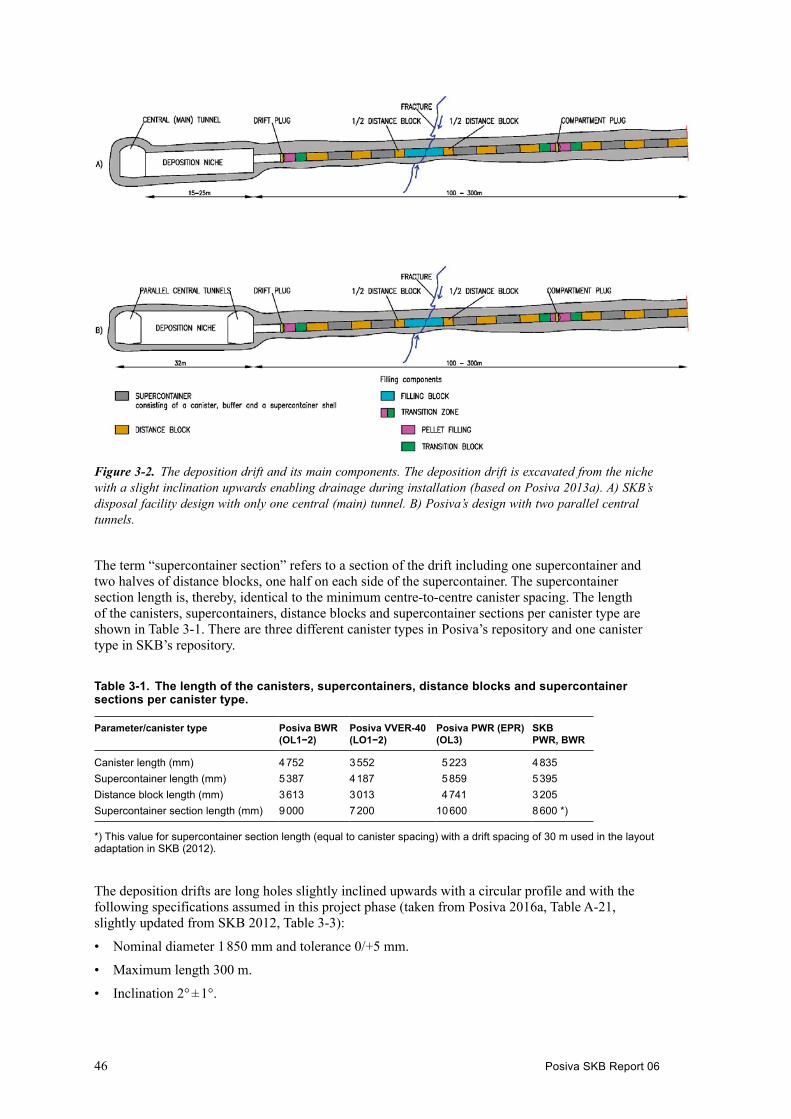
46 Posiva SKB Report 06
The term “supercontainer section” refers to a section of the drift including one supercontainer and two halves of distance blocks, one half on each side of the supercontainer. The supercontainer section length is, thereby, identical to the minimum centre-to-centre canister spacing. The length of the canisters, supercontainers, distance blocks and supercontainer sections per canister type are shown in Table 3-1. There are three different canister types in Posiva’s repository and one canister type in SKB’s repository.
Table 3-1. The length of the canisters, supercontainers, distance blocks and supercontainer sections per canister type.
Parameter/canister type Posiva BWR (OL1−2)
Posiva VVER-40 (LO1−2)
Posiva PWR (EPR) (OL3)
SKB PWR, BWR
Canister length (mm) 4 752 3 552 5 223 4 835Supercontainer length (mm) 5 387 4 187 5 859 5 395Distance block length (mm) 3 613 3 013 4 741 3 205Supercontainer section length (mm) 9 000 7 200 10 600 8 600 *)
*) This value for supercontainer section length (equal to canister spacing) with a drift spacing of 30 m used in the layout adaptation in SKB (2012).
The deposition drifts are long holes slightly inclined upwards with a circular profile and with the following specifications assumed in this project phase (taken from Posiva 2016a, Table A-21, slightly updated from SKB 2012, Table 3-3):
• Nominal diameter 1 850 mm and tolerance 0/+5 mm.
• Maximum length 300 m.
• Inclination 2° ± 1°.
Figure 3‑2. The deposition drift and its main components. The deposition drift is excavated from the niche with a slight inclination upwards enabling drainage during installation (based on Posiva 2013a). A) SKB’s disposal facility design with only one central (main) tunnel. B) Posiva’s design with two parallel central tunnels.

Posiva SKB Report 06 47
• Tolerances for straightness (waviness or deviation from the centre line) ± 10 mm (in the vertical direction) over a length of 6 000 mm, ± 20 mm (in the horizontal direction) over a length of 6 000 mm (Posiva 2016c).
• Tolerances for drift wall roughness ± 0...+ 5 mm (i.e. drift diameter 1 850 + 5 mm).
• Tolerances for drift wall steps ± 0...+ 5 mm (i.e. drift diameter 1 850 + 5 mm).
3.1.2 Groundwater controlThe drainage of the compartment during deposition is achieved by the upward inclination of the drift; water will self-drain along the drift floor out of the drift until the compartment plug or the drift plug is installed (SKB 2012, Section 4.3.1). There will be a drainage hole in the collar of the plugs at the floor level (lowest part of the collar) allowing the leakage water to exit the drift during installa-tion phase. It will be closed when the artificial water filling starts.
Pre-grouting in the pilot hole for the drift can be used to seal water-bearing fractures. Pre-grouting is also planned to be carried out during the reaming of the drift, if needed. For more details, see SKB (2012, Section 9.3.3).
Groundwater control by pre-grouting may not always be sufficiently effective in KBS-3H deposition drifts, especially since grouting holes are not allowed outside the drift contour (Posiva 2016a, Table A-21). Hence an efficient post-grouting methodology is needed. A post-grouting device called Mega-Packer that can handle the conditions at full repository depth has been developed for KBS-3H. The Mega-Packer is a large steel tube with packers at both ends. For more details, see SKB (2012, Section 4.9) and Eriksson and Lindström (2009).
The maximum allowed inflow after post-grouting is 10 L/min per one drift (Posiva 2016a, Table A-21). The allowed inflow rate into a drift can probably be increased if the sliding plate and the pallet of the deposition machine is modified. Drainage is ended when the drainage lead-through in the plug collar has been closed before the artificial water filling is started.
3.1.3 Artificial water filling and air evacuationIn the reference design DAWE, the empty space in the annulus (gap) between the deposition drift wall and the supercontainer, distance block and filling components inside a sealed compartment will be artificially filled with water. This will ensure initial swelling of the buffer and filling components, the development of counter pressure against drift surface, the locking of canisters in place and the prevention of axial displacement and excessive buffer erosion (SKB 2012, Section 4.3.4). More details on the pipes can be found in Section 3.5.3.
In the previous project phase, it was assumed that tap water would be used for artificial water filling (SKB 2012, Section 6.1.2). In the current project phase, two alternative water compositions are considered in the performance assessment, tap water and a simulant to the current groundwater at the repository depth at Olkiluoto, with a TDS content of 10 g/L and Ca2+/Na+ mass ratio of 1:2 (Posiva 2016d, Appendix B, Table 15).
3.2 Design of bufferThe buffer components inside the supercontainer comprise ring-shaped blocks and solid end blocks at both ends. In KBS-3H, the term buffer is also taken to include the distance blocks placed between supercontainers. Both the buffer in the supercontainer and the buffer in the distance blocks are needed to provide the collective functions of the buffer as in KBS-3V, but they have slightly different dimensions, dry densities and initial water contents. The dimensions of the distance blocks and the buffer segments in the supercontainers depend on the canister type, which determines the canister spacing defined in thermal dimensionings. The distance blocks will also be standing on feet (SKB 2012, Section 4.5). The design requirements for buffer are given in Table 2-7. The buffer design is presented in Börgesson et al. (2016). Posiva’s reference method for compression of the blocks is the isostatic compression method (Ritola and Pyy 2011, Posiva 2016e, Section 5.3.2).
48 Posiva SKB Report 06
The buffer components inside the supercontainer can be seen in Figure 1-2 and the distance blocks are shown in brown in Figure 3-2. The reference designs of the bentonite buffer blocks inside the supercontainer are presented in Table 3-2 and the reference design of the distance blocks is presented in Table 3-3. The water content of the distance blocks is higher than in the supercontainer buffer blocks in order to prevent humidity-induced cracking during operation (Posiva 2012c, Section 4.2.2).
Table 3-2. Reference buffer blocks inside the supercontainer (Posiva 2016e, Tables 3-3, 3-4 and 3-15).
Design parameter Nominal design Accepted variation/tolerances
End blocks inside the supercontainerDry density 1 753 kg/m3 ±20 kg/m3
Water content 17 % ±1 %Dimensions Length: 350 mm
Outer diameter: 1 740 mmInner diameter (top block): 798 mmInner diameter (bottom block, bottom with recess): 828 mmInner diameter (bottom block, flat bottom):
±1 mm+1/−2 mm+0/−2 mm+0/−2 mm
Ring-shaped blocks inside the supercontainerDry density 1 885 kg/m3 ±20 kg/m3
Water content 11 % ±1 %Dimensions Length: 890–1 308 mm
Outer diameter: 1 740 mmInner diameter: 1 058 mm
±1 mm+1/−2 mm+1/−2 mm
Table 3-3. Reference buffer block outside the supercontainer (distance blocks) (Posiva 2016e, Tables 3-5 and 3-15).
Design parameter Nominal design Accepted variation
Solid blocks outside the supercontainer (distance blocks)Dry density 1 712 kg/m3 ±20 kg/m3
Water content 21 % ±1 %Dimensions Outer diameter: 1 765 mm ±1 mm
3.3 Design of filling componentsIn the KBS-3H design, filling components are used in drift sections where supercontainers cannot be emplaced. The design requirements for the main filling components are given in Table 2-9. The design of the filling components is presented in Börgesson et al. (2016). Altogether, there are six types of filling components:
1. Filling adjacent to drift plug (compartment side), including transition block (green in Figure 3-2) and pellet filling (pink); together termed transition zone.
2. Filling in inflow position (termed filling block; cyan in Figure 3-2).
3. Filling on entrance side of compartment plug (transition block in green, pellets in pink in Figure 3-2); together termed transition zone.
4. Filling on drift end side of compartment plug (transition block in green, pellets in pink); together termed transition zone.
5. Filling at the drift end.
6. Filling of the remaining pilot hole stump at the end of the drift.

Posiva SKB Report 06 49
Filling blocks (#2 in the list above) are used in drift sections where relatively high initial ground-water inflows (> 0.1 L/min) render the sections unsuitable for supercontainer and distance block emplacement.
For installation reasons, transition zones are required on either side of a compartment plug (#3, #4) to separate the plug from distance blocks. The dimensions of the transition zones are shown in Figure 3-3. The purpose of the transition zone on the sealed side of the compartment plug is to fill the empty drift section next to the plug that is needed for mounting the plug in a way that supports the performance of the adjacent distance block. The purpose of the transition zone on the drift entrance side of the compartment plug is to function as backfilling material supporting the performance of the adjacent drift components. A transition zone (#1, similar to the one installed on the sealed side of a compartment plug) will be installed between a drift plug and an adjacent distance block.
The filling components are planned to be composed of the same clay material as the distance blocks or buffer blocks inside the supercontainer. The conceptual design of the filling components is based on the use of pellets and cylindrical blocks of solid, compacted bentonite, similar to distance blocks (the dry density is the same). The dimensions of the filling components are given in Posiva (2016e) and Börgesson et al. (2016). In particular, the length of a filling block is dependent on the inflow rate and the orientation of the transmissive fracture (Posiva 2016e, Section 3.4.2).
A filling component (#5 in the list above) is emplaced in the KBS-3H deposition drift end between the drift face and the adjacent distance block (Posiva 2016e, Section 3.4.4). The remaining pilot hole beyond the end of drift is filled (#6) to avoid possible open cavities that might reduce the density of buffer and filling components. Another objective is to seal the pilot hole to prevent possible groundwater flow between drift and host rock (Posiva 2016e, Section 3.4.5).
3.4 Design of compartment and drift plugsThe compartment plugs of KBS-3H are used to hydraulically separate and seal sections (~150 m at most) of the drift and they also enable the artificial water filling procedures of DAWE (see Section 3.1.3). The plug (Figure 3-4) consists of three titanium components: the fastening ring, the collar, which is attached to the fastening ring, and the cap, as well as one cementitious component, the low-pH concrete casting which is used to cast the fastening ring into a prepared rock notch. The collar is fastened to the fastening ring by welding as is the cap to the collar. The overall principle of the plug is shown in Figure 3-4.
The mouth (i.e. entrance) of the drift will be sealed with a drift plug. The drift plug is very similar to the compartment plug (discussed above and shown in Figure 3-4).
Figure 3‑3. Schematic drawing of the filling components adjacent to a compartment plug. The same design and dimensions are used for the transition zone adjacent to a drift plug as for the transition zone on the sealed side (i.e. left) of the compartment plug (Posiva 2016e, Figure 3-16). The entrance of the drift is to the right. The figure is not to scale.

50 Posiva SKB Report 06
The function of the drift plug is similar to that of KBS-3V deposition tunnel plugs; it serves to prevent water flows out of the drift, which could give rise to piping and erosion of the buffer, either through the plug itself, or through the adjacent rock. It also keeps the buffer and filling components in place prior to the backfilling and saturation of the adjacent central tunnel (SKB 2012, Section 4.8.1). The drift plug also enables the water filling procedures of DAWE (Posiva 2016f, Section 3.1). The design requirements for the plugs are given in Table 2-11.
The present reference design of the plugs originates from the prototype of the compartment plug that was developed during 2009 and 2010 with the objective to verify the ability to divide a KBS-3H drift into hydrologically separated compartments. Tests on the prototype (with steel as material) at Äspö were successful and it was shown that the design fulfilled the set up test criteria (Posiva 2016f, Section 3.1). Modifications to the design have been proposed due to difficulties in welding and inspecting welds (Posiva 2016f, Section 3.2) but whether they will be implemented or not will be decided in future project phases. The proposed changed are, therefore, not discussed in this report.
Based on the long-term performance aspects, titanium has been selected as the plug material. The plugs shall be manufactured in Titanium Grade 3 or Grade 12 (ASTM). Titanium Grade 3 and 12 have similar mechanical properties and either one can be chosen depending on availability (Posiva 2016f, Section 3.3).
3.5 Design of supercontainer shell and other minor components3.5.1 Supercontainer shellIn the KBS-3H variant, the canister, surrounded by bentonite buffer, is emplaced in the deposition drift in a prefabricated package, the supercontainer, which is held together by an outer metal shell (Figure 1-2), made of titanium according to the current reference design (this may change in the future, see Section 9.2.5). The supercontainer shell is perforated to allow the bentonite inside the supercontainer to become wetted and to swell, and thus to fill the void spaces between the super-container and the drift. The supercontainer shell will be provided with metal feet to elevate it from the drift floor. The design requirements for the supercontainer shell are given in Table 2-14.
The thickness of the shell and the end plates is 6 mm (for titanium) and the outer diameter is 1 761 mm. The cylinder part of the shell is perforated (perforation degree 61−62 %, hole diameter 10 cm) but the end plates are solid (Posiva 2016g, Section 3-4).
3.5.2 Spray and drip shieldsSpray or drip shields, thin titanium sheets, will be mounted in positions of water spraying or dripping from the host rock in order to protect the buffer against mechanical erosion, allowing the leakage
Figure 3‑4. Section view of the compartment plug (Posiva 2016f, Figure 3-1). The reference design of the drift plug is similar to the compartment plug (Posiva 2016f, Section 3.1).

Posiva SKB Report 06 51
water to flow freely down the drift walls to the floor (SKB 2012, Section 4.3.1). The sheets are shaped to follow the rock surface tightly (see Anttila et al. 2008, Section 4.2.2 for more information). Drip shield type titanium plates can also be used at locations where a piece of rock has fallen from the drift wall (so-called outbreak). Such holes will be filled with bentonite and covered with a titanium plate. The spray and drip shields must not hinder the installation of the drift components.
3.5.3 Artificial water filling and air evacuation componentsThe artificial water filling discussed in Section 3.1.3 will be done by pumping water through the compartment or drift plug via water filling pipes. The water filling pipes extend approximately two metres into the drift and extend behind the pellet-filled section underneath the transition block, see Figure 3-5. During the water filling, air will be compressed and accumulated at the end of the drift compartment due to its slightly upward inclination. This trapped air is evacuated through a pipe with a maximum length of 150 m. In the compartment end, the air evacuation pipe is extended with a short bottom pipe to the highest point of the drift to ensure complete water filling, see Figure 3-6. After the water filling is completed, the pipes are retracted out from the compartment and removed.
Using short water filling pipes makes their removal easy and leaves just one long pipe, the air evacuation pipe, to be removed, which speeds up the pipe removal process considerably. The removal of water filling pipes and air evacuation pipes is of critical importance to the DAWE design. In order to avoid unnecessary foreign materials, all pipes cannot be left in the drift. Both the water filling pipes as well as the air evacuation pipe can be removed in a feasible timeframe, i.e. within the first day after water filling (SKB 2012, Section 6.3.2).
3.5.4 Parking feetDistance blocks, filling blocks and transition blocks will be standing on feet (50 mm) (SKB 2012, Sections 4.4.1 and 4.5.1), which are currently planned to be made of titanium. Such feet allow the inflowing water from the rock to flow freely along the drift floor during the installation without being in direct contact with the bentonite. The feet are also needed due to installation reasons.
Figure 3‑5. Watering and air evacuation pipes: main components of the water filling system with short pipes through the compartment plug (similar design for the drift plug). The three short water filling pipes lead the water past the pellet-filled section to a position underneath the transition block (after Posiva 2016f, Figure 3-10).

52 Posiva SKB Report 06
Part of pipe that is left inside the drift
Check valve housing that is left inside the drift
Figure 3‑6. Location of the air evacuation pipe at the rear end of the drift. The short pipe in the rear part of the drift (compartment) that is turned upwards to the roof is needed because the air is accumulated in the upper part of the inclined drift (Posiva 2016f, Figure 3-12).

Posiva SKB Report 06 53
4 Production lines for the KBS-3H disposal facility
4.1 OverviewFor the construction of the KBS-3H repository, Posiva and SKB have defined a set of production lines (PL):
• (The spent nuclear fuel.)
• (The canister.)
• The buffer and filling components.
• The supercontainer.
• The plugs.
• The underground openings, and
• (the closure, including backfill of the main/central tunnels).
The production lines without parentheses are reported in new separate KBS-3H-specific Production reports, and in addition there is an overarching Repository Production report (Posiva 2016h), which presents an overview of the various production lines and the common basis for these reports. The production lines within parentheses above are, with minor exceptions, essentially generic to both the KBS-3V and KBS-3H disposal variants. Reference is therefore made to the corresponding KBS-3V reports produced by Posiva and SKB. Identified differences between KBS-3V and KBS-3H are accounted for in Posiva (2016h).
The set of KBS-3H production line reports addresses design premises/design basis, reference design, conformity of the reference design to design premises/design basis, production and the initial state, i.e. the results of the production. Thus, the reports provide input to any KBS-3H safety assessment concerning the characteristics of the as-built KBS-3H repository and to any KBS-3H repository operation concerning the handling of the engineered barriers and construction of underground openings.
The SKB 3V Repository production report (SKB 2010a) was produced ahead of the 3V component PLs and served the purpose of presenting the necessary background, judicial and regulatory frame-work and introduced and discussed the various design and functional elements of the repository, allowing the component PLs to make reference to the repository production PL. In the case of KBS-3H the process is somewhat retrograde. The various KBS-3H component PLs as well as the KBS-3H Design Basis report (Posiva 2016a) have been developed essentially independent of the 3H Repository Production report. The latter has overall been produced posterior to the PLs and thereby more serves as an umbrella KBS-3H production document, also handling references to those production reports which are common to KBS-3V. Also, the 3H Repository Production report does not, unlike its KBS-3V predecessor, play any specific role in any license application.
The individual reports that form the set of production reports and their short names used as references within the set of production reports are illustrated in Figure 4-1.
4.1.1 The productionThe production of the engineered barriers comprises:
• Specification of the design of the components to be delivered or produced.
• The methods to manufacture and inspect/verify the specified designs.
• A physical production line that delivers components and ultimately the (composite) engineered barriers conforming to the specified designs.
The production lines refer to all activities and stages required to produce the engineered barriers and install them in a KBS-3H repository.

54 Posiva SKB Report 06
For the underground openings, the specified design is the result of the application of a design methodology to successively adapt the design to the conditions at the site. Methods for inspection comprise methods to investigate the host rock before the construction is initiated, methods to control the construction as well as inspection of the as-built underground openings. No explicit production line as per the engineered barriers is outlined for the underground openings. However, the methods to construct the different underground openings and their ability to result in underground openings that conform to the design basis are presented.
4.1.2 The production linesProduction lines have been produced for each of the KBS-3H specific engineered barriers, i.e. the buffer and filling components (Posiva 2016e) and the plugs (Posiva 2016f), as well as for the supercontainer (Posiva 2016g) and the underground openings construction (Posiva 2016c). Notably, no separate KBS-3H specific production line reports are produced for spent fuel, canister or closure (including backfill), where it is by and large assumed that the KBS-3V specific production line reports are applicable also to KBS-3H.
An overview of the main components of the respective production lines of the engineered barriers is given in Figure 4-2. The figure also illustrates the main components of the handling of the spent nuclear fuel and its relationship to the construction of the underground openings.
Furthermore, an umbrella-type KBS-3H repository production report (Posiva 2016h) is introduced, which summarises the design basis, the production line specifics of the KBS-3H barriers and supercontainer, and the construction of the underground openings.
4.1.3 Design and production line interfacesThere are mutual dependencies in terms of design basis that need to be fulfilled in order for the different parts of the repository to co-function properly during the production of the KBS-3H repository. These interfaces are in the following outlined for the production lines of the engineered barriers, the supercontainer and for the construction of the underground openings. The corresponding dependencies for the spent nuclear fuel, canister and closure production lines are only tentatively described in conjunction of the accounting of the repository production report. For each of the KBS-3H specific engineered barriers and underground openings the design basis related to the technical feasibility as imposed by other parts in the KBS-3H repository is summarised, whereas detailed descriptions are given in the respective production report.
In many cases the interfaces between the production lines result from the design basis the different parts of the KBS-3H repository mutually impose on each other and/or are consequences of interfaces between the production lines, as outlined in the ensuing sections.
In addition to design basis related to technical feasibility, there are design interfaces related to the functions that the different parts of the KBS-3H repository need to sustain and maintain in the long-term time perspective. These interfaces and interdependencies are related to the long-term evolution of the KBS-3H repository and are presented in detail in the KBS-3H Design Basis report (Posiva 2016a); see also Chapter 2.
Spent fuel report
Canister production report
Repository production report
Super-container production report
Buffer and fillingcomponent production report
Plug production report
Closure production report
Underground openings construction report
Figure 4‑1. The set of KBS-3H production reports and their short names. The canister, buffer and filling components, plug and closure (including backfill) production reports are commonly referred to as “engineered barrier” production reports.

Posiva SKB Report 06 55
4.2 The buffer and filling components4.2.1 Overview The KBS-3H buffer and filling components are divided into “buffer components” and “filling components”. The design basis for these components is provided in Sections 2.4 and 2.5, respectively, whereas the reference design is described in Sections 3.2 and 3.3, respectively.
The main parts of the buffer and filling components production line are illustrated in Figure 4-2, and a description of all stages of production is given in the Buffer and Filling Component production line report (Posiva 2016e).
Production, assembly, transportation, handling and installation of the buffer and filling componentsThe buffer and filling component production line begins with the procurement of bentonite material, continues with the manufacturing of buffer and filling components, which is followed by the interim storage of the components, the preparation of the drift, assembly of the supercontainer, the installation of the supercontainer and various buffer and filling components into the deposition drift, removal of any temporary elements from the deposition drift and finally completing the filling procedure by plugging the drift.
Manufacturing and installation of buffer and filling components have been carried out and verified that the components can be produced and installed as planned (Posiva 2016e, Kronberg 2015).
Figure 4‑2. Overview of the main activities in the handling of the spent fuel, the production of the KBS-3H engineered barriers and supercontainer and the construction of the KBS-3H underground openings (SKB 2012, Figure 9-2).
56 Posiva SKB Report 06
Initial state of the buffer and filling componentsThe initial state of the buffer is the state when all the auxiliary equipment used during installation has been removed and all buffer and filling components have been installed in the deposition drift and when the compartment or entire drift has been sealed by a plug. Artificial water filling (DAWE) of the deposition drift or inflow of groundwater to the drift and their impact on the buffer are not accounted for in the initial state. For the assessment of the long-term safety it is confirmed that the buffer at the initial state conforms with the design basis related to the safety functions in the reposi-tory. The conformity of the reference design with the design basis and conformity of the installed buffer with the reference design has been demonstrated (Posiva 2016e, Kronberg 2015).
The description of the initial state includes a range of densities and other properties both for buffer components and the buffer as a whole. However, based on calculations it can be stated that the average saturated buffer density will be between the limits set for the saturated density of the buffer in almost all possible combinations of acceptable deposition drift dimensions and buffer block, filling block and pellet densities and geometries used here (Posiva 2016e).
4.2.2 Design interfacesThe canister and the supercontainer shell geometries and groundwater conditions (inflow and chemistry) impose design basis on the KBS-3H buffer. The canister imposes that the buffer blocks within the supercontainer shall have a cylindrical hole large enough to allow emplacement of the canister. The dimensions and tolerances of the buffer shall, in relation to the supercontainer shell and the canister, be such as the buffer can be placed inside the supercontainer shell and later allow for installation of the canister. Furthermore, in order to achieve the desired swelling pressure of the bentonite buffer in the supercontainer section, the buffer sets design basis on the diameter of the deposition drift, indirectly on the diameter of the supercontainer (shell) and the resulting annular space between the two. A similar optimisation exists between the diameters of the distance blocks, filling blocks and transition blocks and the deposition drift.
4.2.3 Production line interfacesThe buffer and filling components production line has interfaces to the canister production line and to the construction of underground openings, i.e. preparation of deposition drifts. The production lines of the canister and buffer merge in the KBS-3H repository in connection to the deposition. The installation of the buffer and filling components comprises several stages as described by Posiva (2016e, cf. Section 5.5 therein). Once the supercontainer (shell, buffer blocks and canister) has been assembled, cf. Section 4.3.3, it is ready for deposition in the deposition drift. The interfaces to the production lines of the supercontainer and construction of underground openings are described in Sections 4.3.3 and 4.5.3, respectively.
4.3 Supercontainer4.3.1 OverviewThe supercontainer, cf. Figure 1-2, is not a barrier in itself but serves as a pre-assembled carrier of two main barriers, the canister and the buffer, held together by an outer perforated metal shell. The design basis of the latter is provided in Section 2.8 whereas the reference design is presented in Section 3.5.1. The supercontainer is made up of the following components (Posiva 2016g):
• Canister (copper/cast iron canister), containing the spent fuel.
• Bentonite buffer.
• Metallic perforated shell.

Posiva SKB Report 06 57
ManufacturingThe production system for the manufacturing of supercontainers comprises a network of suppliers who manufacture the supercontainer shell and an assembly facility (reloading station) where the assembly and final inspections will be carried out. Foreseen parameters to inspect during manufacturing include material properties, dimensions, shape and welds.
Manufacturing of a titanium supercontainer shell has not been carried out yet. So far only two prototype supercontainers have been manufactured for the testing/demonstrations of the deposition machine, one in carbon steel and one in stainless steel. The performed manufacturing has, however, verified that it is possible to manufacture supercontainer shells within specified tolerances.
AssemblyIn Posiva’s case the assembly is performed in the reloading station without employing a radiation shielded handling cell, for more details see Posiva (2016g). The assembly of the supercontainer will in SKB’s case be carried out in a radiation shielded handling cell at the reloading station under-ground. The reloading station will be equipped with necessary lift arrangements for handling of the different components. The assembly is performed with the supercontainer in a vertical position. To enable lifting and tilting from vertical to horizontal position and transport of the supercontainer after assembly, the supercontainer is placed in a so-called transport tube, cf. Figure 4-3.
The assembly of the supercontainer includes the following main steps as illustrated in Figure 4-3.
Figure 4‑3. Illustration of the supercontainer assembly. The illustration is also showing the stiffening plates on the supercontainer shell that will be removed after installation of the buffer and before the transport tube is introduced.
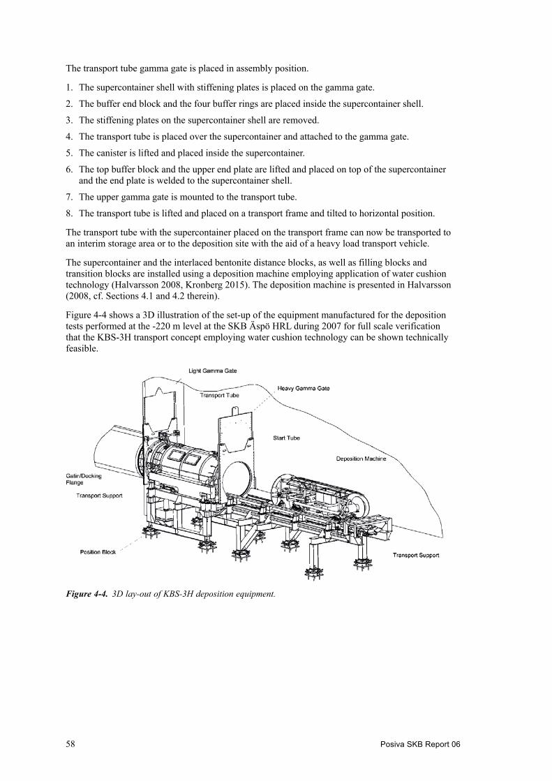
58 Posiva SKB Report 06
The transport tube gamma gate is placed in assembly position.
1. The supercontainer shell with stiffening plates is placed on the gamma gate.
2. The buffer end block and the four buffer rings are placed inside the supercontainer shell.
3. The stiffening plates on the supercontainer shell are removed.
4. The transport tube is placed over the supercontainer and attached to the gamma gate.
5. The canister is lifted and placed inside the supercontainer.
6. The top buffer block and the upper end plate are lifted and placed on top of the supercontainer and the end plate is welded to the supercontainer shell.
7. The upper gamma gate is mounted to the transport tube.
8. The transport tube is lifted and placed on a transport frame and tilted to horizontal position.
The transport tube with the supercontainer placed on the transport frame can now be transported to an interim storage area or to the deposition site with the aid of a heavy load transport vehicle.
The supercontainer and the interlaced bentonite distance blocks, as well as filling blocks and transition blocks are installed using a deposition machine employing application of water cushion technology (Halvarsson 2008, Kronberg 2015). The deposition machine is presented in Halvarsson (2008, cf. Sections 4.1 and 4.2 therein).
Figure 4-4 shows a 3D illustration of the set-up of the equipment manufactured for the deposition tests performed at the -220 m level at the SKB Äspö HRL during 2007 for full scale verification that the KBS-3H transport concept employing water cushion technology can be shown technically feasible.
Figure 4‑4. 3D lay-out of KBS-3H deposition equipment.

Posiva SKB Report 06 59
4.3.2 Design interfacesThe thickness of the buffer blocks imposes design basis on the supercontainer (with its cylindrical shell), the latter in turn imposes design basis on the geometry of the deposition drifts. Specifically, the outer diameter and the length of the supercontainer impose design basis on the geometry and shape (minimum diameter, straightness and undulation) of the deposition drift. Other design basis imposed by the supercontainer includes those related to handling of the buffer and the canister.
The spent nuclear fuel canister imposes design basis on the supercontainer in that it should be able to host five canister varieties of four different lengths, as furnished by the Posiva (N=3) and SKB (N=2) programmes, respectively.
4.3.3 Production line interfacesThe supercontainer production line has interfaces to the canister, buffer and filling components production lines and to the construction of underground openings (i.e. preparation of deposition drifts). The assembly of the supercontainer, including installation of the canister and the buffer, comprises several stages as described in the supercontainer production report (Posiva 2016g), see also Figure 4-3. After the cylindrical bottom end block and the ring-shaped buffer blocks have been introduced in the metallic shell of the supercontainer, the canister is inserted followed by emplace-ment of the cylindrical top end block. Once the supercontainer has been assembled, it is ready for deposition in the deposition drift. The interface to the construction of underground openings is presented in Section 4.5.3.
4.4 Plugs4.4.1 OverviewThe compartment plugs are used to hydraulically separate sections (~150 m long) of the deposition drift and they also enable the water filling procedures of DAWE. The design basis is provided in Section 2.6 and the reference design is provided in Section 3.4.
The compartment plug and the drift plug both consist of the following three main components, cf. Figure 3-4:
• Fastening ring.
• Collar (with bushings/lead-throughs for watering and air evacuation pipes).
• Cap (with connection for pellet filling).
The lead-throughs/bushings for artificial watering and air evacuation pipes facilitate the DAWE procedure, see SKB (2012), Kronberg (2015) and Posiva (2016f), for administering artificial water after completed disposal in a given compartment of a deposition drift.
Conformity to reference designThe preliminary FEM calculations performed for the drift plug, based on a modified version of the compartment plug, using titanium, show that the design has potential to constitute a viable solution enabling fulfilment of the high requirements applicable once the deposition process is completed. The drift plug analysis presented in Posiva (2016f) is considered conservative with regards to the swelling pressure.
The final design for the drift plug is expected not to differ all that much from that of the compart-ment plug, other than with regards to the thickness of the cap to withstand the swelling pressure.
The mechanical strength of the compartment plug design was checked during the test installation conducted during the winter 2008/2009 at the −220 m level of the Äspö HRL demonstrating in situ at full scale that the compartment plug can withstand a hydrostatic pressure of 5 MPa (SKB 2012).

60 Posiva SKB Report 06
Laboratory tests have been performed with the objective of obtaining information about the develop-ment of swelling pressure from the bentonite buffer and the corresponding required pulling force required to loosen the pipe resting on small support inside the test cell (SKB 2012). Pipe removal was also demonstrated in situ at full scale during the installation of the KBS-3H Multi Purpose Test (MPT) at the Äspö HRL. The air evacuation pipe was in this case, however, only c. 20 metres long, compared with the maximum assumed length of 150 metres for a single compartment.
Manufacturing of the plugsThe manufacturing of the plugs is made in an external workshop. The plug components are manu-factured from titanium plates where the manufacturing consists of a number of steps. SKB/Posiva intends to apply conventional and generally applied methods both for the involved processes and inspections, for details see Posiva (2016f). In order to verify that the different components fit to each other, a preassembly of the plugs will be performed in the workshop before delivery, without employing assembly welds.
Installation of the plugsThe installation/assembly of the plugs will be carried out inside the deposition drift. Manual instal-lation of compartment plugs has been demonstrated in tests carried out during the winter 2008/2009 and during the MPT, both carried out at Äspö HRL. It is projected that future installations will be performed with some kind of remotely controlled handling device, including automatisation of welding.
The preparation of the drift includes excavation of the rock notches followed by casting of the fastening ring with concrete and installation of the air evacuation pipe (notably a temporary “bridge” over the fastening ring is required to enable passage by the deposition machine). The closure of the compartment (or drift) includes installation of the collar with pipes that run through it and instal-lation of the cap. Once all welding is finalised, the interfaces between the plug and concrete and between the concrete and the rock surface are contact grouted using the preinstalled injection tubes. Directly after the cap has been installed, the void between the plug and the transition blocks is filled with pellets. After filling the pellets, the filling connection is closed, as well as the drainage pipe in the collar in its lowest part, and the water filling starts. The water filling is continued until water comes out through the air evacuation pipe. Immediately after closing the valves, the water supply lines are disconnected and pipe removal commences. A detailed account of the installation process including the various inspections to be made are given in Posiva (2016f).
Initial state of plugsThe initial state of the compartment plug and the drift plug is the state when the water filling has been completed, all penetrating pipes have been retracted and the lead-throughs have been sealed. For the assessment of the long-term safety it shall be confirmed that the plugs at the initial state conforms to the design basis related to the safety functions in the final repository.
Manufacturing inspections of the plugs will verify that the material properties conform to the speci-fied values needed to withstand the anticipated loads. The proposed materials are in accordance with ASTM standards, hence the property variations are small.
Manufacturing inspections of the plugs shall verify that dimensions conform to the specified values. Plugs manufactured so far for performed tests have verified that it is possible to manufacture plugs within specified tolerances. It is, however, noted that plugs have so far only been manufactured of carbon steel.
The compartment plug shall maintain its hydraulic isolation capacity during the installation phase and the drift plug shall as a minimum maintain its hydraulic isolation capacity as long as the adjacent central/main tunnels are not backfilled and saturated. Performed in situ tests have verified that it is possible to reach the acceptance criteria (a tentative leakage criterion of 0.1 L/min) for water leakage through the plugs. Low-pH concrete was however not used in any of the tests (still to be tested). Actual water leakage can be measured in conjunction with the water filling of the compartment.

Posiva SKB Report 06 61
4.4.2 Design interfacesThe various steps in the plug production line are outlined in Figure 4-1 and are described in detail in the Plug production line report (Posiva 2016f).
In the KBS-3H repository, during the post-closure phase, the plugs must not significantly impair the safety function of the other engineered barriers or rock. Design basis is imposed by the buffer and filling components while the compartment and drift plugs are important for the properties and function of the buffer and filling components, above all to keep the components in place. This implies that the requirements for the drift plug are considerably higher than those for the compart-ment plug, cf. the Plug production line report (Posiva 2016f).
The plugs in turn impose demands on the rock and the construction of the deposition drift. This includes design basis related to inflow, strength of the rock and fracturing at the positions of the plugs and preparation of v-shaped notches to host the fastening ring, cf. Figure 3-4.
4.4.3 Production line interfacesThe Plug production line includes a series of activities, e.g. the selection of optimal positions for the plugs, preparation of the v-shaped notch in the drift wall and mounting of the fastening ring followed by mounting of the collar and cap, cf. Posiva (2016f). Alongside the plug installation work, attachment of the pipes for air evacuation is made to the drift wall of the compartment with lead-throughs associated with the respective plug. The buffer and filling component production and plug production lines merge in conjunction with the installation of the plug and the subsequent administering of bentonite pellets between the transition block and the plug, cf. Posiva (2016e).
4.5 Underground openings construction4.5.1 OverviewThe construction of the underground openings comprises site adaptation of the design and descrip-tion of the application of the methods to excavate and inspect (as built) the underground openings. The preparation of the underground openings for the installation of supercontainers and other drift components and closure is also included. The underground openings here comprise:
• The actual location and spatial geometry of the underground openings.
• The rock surrounding the openings that is affected by the construction works, and
• engineered materials for sealing and rock support, and residual materials from performance of activities in the disposal facility, which remain in and on the rock bounding the openings at deposition and closure.
The void spaces of the underground openings as such do not contribute to the safety of the KBS-3H repository and do not have any safety functions. However, the locations of the deposition areas and deposition drifts with respect to the ambient geological, thermal, hydrogeological, mechanical and chemical properties of the rock are important for the performance of the host rock as a barrier and thus for the safety of the repository.
The applicable design basis related to the host rock and the underground openings is presented in Section 2.2 whereas the reference design is provided below.
Reference design and conformity to design basisThe reference design is based on one possible layout of the underground disposal facilities at Olkiluoto (Figure 4-5) and at Forsmark, respectively. The reference design also provides an estimation of material quantities required for rock support and grouting based on the layout. The site-specific basis for the reference design is site characterisation data, site descriptive models and geotechnical information, which have been interpreted and evaluated in a site engineering report (SER) for KBS-3V. Posiva’s SER for the Olkiluoto site is presented in Posiva (2013d) with the corresponding Forsmark SER presented in SKB (2009b).
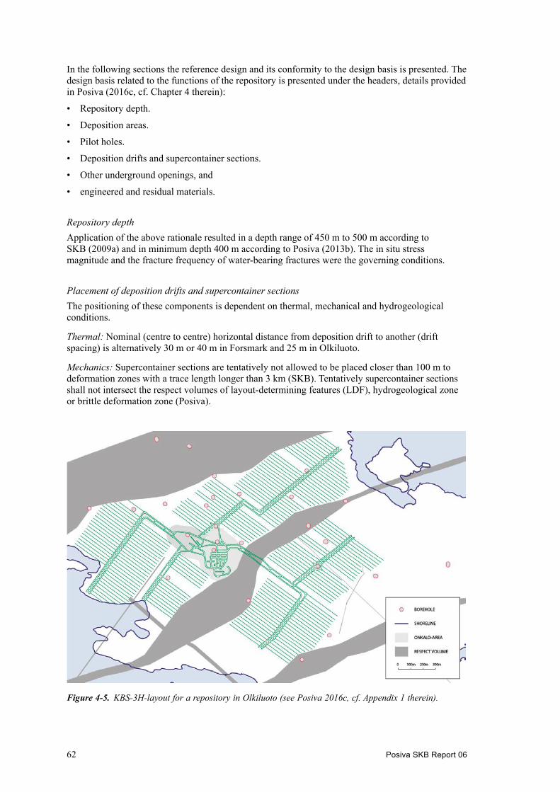
62 Posiva SKB Report 06
In the following sections the reference design and its conformity to the design basis is presented. The design basis related to the functions of the repository is presented under the headers, details provided in Posiva (2016c, cf. Chapter 4 therein):
• Repository depth.
• Deposition areas.
• Pilot holes.
• Deposition drifts and supercontainer sections.
• Other underground openings, and
• engineered and residual materials.
Repository depthApplication of the above rationale resulted in a depth range of 450 m to 500 m according to SKB (2009a) and in minimum depth 400 m according to Posiva (2013b). The in situ stress magnitude and the fracture frequency of water-bearing fractures were the governing conditions.
Placement of deposition drifts and supercontainer sectionsThe positioning of these components is dependent on thermal, mechanical and hydrogeological conditions.
Thermal: Nominal (centre to centre) horizontal distance from deposition drift to another (drift spacing) is alternatively 30 m or 40 m in Forsmark and 25 m in Olkiluoto.
Mechanics: Supercontainer sections are tentatively not allowed to be placed closer than 100 m to deformation zones with a trace length longer than 3 km (SKB). Tentatively supercontainer sections shall not intersect the respect volumes of layout-determining features (LDF), hydrogeological zone or brittle deformation zone (Posiva).
Figure 4‑5. KBS-3H-layout for a repository in Olkiluoto (see Posiva 2016c, cf. Appendix 1 therein).

Posiva SKB Report 06 63
Tentatively deposition drifts shall not intersect the respect volumes of LDFs (Posiva). SKB does not have the corresponding requirement.
Canister positions should, as far as reasonably possible, be selected so that they do not have potential for shear larger than the canister can withstand. In order to mitigate the impact of potential future earthquakes, canister positions are selected so that they do not intersect discriminating fractures, so-called “Large fractures”. Criteria to be applied in selecting canister positions from this point of view are addressed in Hellä et al. (2016).
Hydrogeology: Based on current experiences the maximum inflow to the deposition drift after grouting is set to be less than or equal to 10 L/min in a 300 m long deposition drift (related to the performance of the deposition machine).
The total volume of water flowing into a supercontainer section (i.e. a drift section containing one supercontainer and two halves of distance blocks on either side of the supercontainer), for the time between when the buffer is exposed to inflowing water and saturation, should be limited to less than or equal to 0.1 L/min (no grouting is allowed in a supercontainer section).
Pilot holesPilot boreholes serves dual purposes, to cater for detailed site investigations and to serve as geometrical guide for the step-wise reaming of the drift. The reference method is to drill a steered core-drilled pilot hole (diameter 76 mm) that is subsequently reamed to full drift size, by way of an intermediate full face reaming step (to diameter c. 300 mm).
Geometrical requirements and tolerances applicable for deposition drifts are imposed by the buffer, filling components and the supercontainer. Given the excavation sequence employed some of these requirements and tolerances are introduced already in conjunction with the cored pilot hole drilling. The applicable design basis for the deposition drifts concerns the straightness, inclination, waviness, diameter, steps and roughness, of which the three first criteria also need to be fulfilled for the pilot holes (Posiva 2016c, cf. Section 2.3.1 therein);
• The horizontal deviation of the pilot hole and deposition drift shall be < 2 m from the nominal end position at a distance of 300 m.
• A positive 2° ± 1° inclination (pilot hole and deposition drift) is needed for drainage, and
• the centre line waviness (deviation) must be kept within ±10 mm (in vertical direction) over a length of 6 000 mm (SKB 2012) and ±20 mm (in horizontal direction) to prevent the supercon-tainer from contacting the rock surface during transport in the drift.
Deposition drifts and supercontainer sectionsThe likelihood of spalling in deposition drifts could be significantly reduced – if not eliminated – by aligning the deposition drifts near parallel to the maximum horizontal stress (Bäckblom 2008). The deposition drifts shall be aligned within ±30 degrees of the orientation of the maximum horizontal stress in order to significantly reduce the risk of spalling in deposition drifts. Additional insights in the spalling phenomena associated with a KBS-3H repository are provided by Suikkanen et al. (2016), who report a spalling depth limited to a maximum of 50 mm and a judgement that the spalled zone is discontinuous, based on in situ experiments and observations made in ONKALO.
Spalling in deposition drifts due to excavation-induced stresses is permitted, but the final deposition drift geometry must conform to the tolerances specified in the design basis. Uncertainties related to the in situ stress conditions, rock properties and the capability to model the extent of spalling and related changes in transmissivity, restrict a verification of the reference design at this stage. The contingency measure for reducing or eliminating spalling in deposition drifts is to align the deposition drifts near parallel to the maximum horizontal stress. In the event that spalling occurs in the deposition drifts, mitigation measures would need to be taken in effect to increase the likelihood of achieving conformity to the above design basis. Thermally induced spalling is possible when the drift has been closed. One potential mitigation of this issue is the possible establishment of a sufficiently high counter pressure introduced by the swelling bentonite.

64 Posiva SKB Report 06
Engineered and residual materialsThe following design basis is applicable to deposition drifts:
• Only clay-based materials for filling of outbreaks and no cement based grouts for possible rock bolting (mechanical bolts).
• No shotcrete is allowed.
• No grouting (SKB 2012) nor bolting is allowed in supercontainer sections (a drift section containing one supercontainer and two halves of distance blocks, one half on either side of the supercontainer).
• Only non-cementitious grouts (silica-based) are allowed in pre-grouting (in the pilot hole) and in post-grouting of the deposition drift using the Mega-Packer technique.
The proposed rock support in underground openings are based on extensive underground construc-tion experience and also identifies which categories of rock support, e.g. rock bolts (and shotcrete in other underground openings than deposition drifts) that are considered suitable for use.
Test results performed at Äspö HRL (Eriksson and Lindström 2008) indicate that the sealing efficiency of Mega-Packer post-grouting will be sufficient and that the reference design conforms to the specified inflow limits. This said, future work includes studies to determine the upper limit of inflow to the deposition drift that can be managed with grouting using colloidal silica.
Engineered materials originating from rock support and grouting activities will remain in the repository after closure of the disposal facility. Residual materials from the operation of the disposal facility will also remain in the facility.
The structural reinforcement elements included in the rock support of deposition drifts are possible rock bolts and non-cementitious grouts for bolt installation or mechanical bolts and clay-based mate-rial for filling of the outbreaks. Spray and drip shields and materials filling cavities are employed in connection with water leakages. No metal scrap attached to the surface or cavities of the drifts are allowed to be left in the drift so that they may give rise to a hydraulic connection between canister positions (SKB 2012).
For all excavation methods, there will be spills of materials; e.g. steel, hard metal and hydraulic oils. There is a need to update the evaluated amounts of engineered and other residual materials in KBS-3H repository for Olkiluoto, given the new current layouts and volumes.
Reference methods Construction of deposition driftsThe reference method for excavating the deposition drifts is the full-face horizontal push-reaming technique, cf. Figure 4-6. Prior to the installation of the buffer the conformity to the criteria set forth in relation to size of fractures intersecting the deposition drift (canister positions), groundwater inflow, connected transmissivity of the EDZ (Excavation Damaged Zone) and geometrical tolerances applicable to the design basis including e.g. the Rock Suitability Classification shall be demonstrated and the deposition drift prepared for installation of the distance blocks, supercontainers and filling components.
Figure 4‑6. Principal illustration of horizontal push-reaming. From the left: pilot hole, reamer head and two stabilisers in the already excavated drift. Courtesy: Atlas Copco.
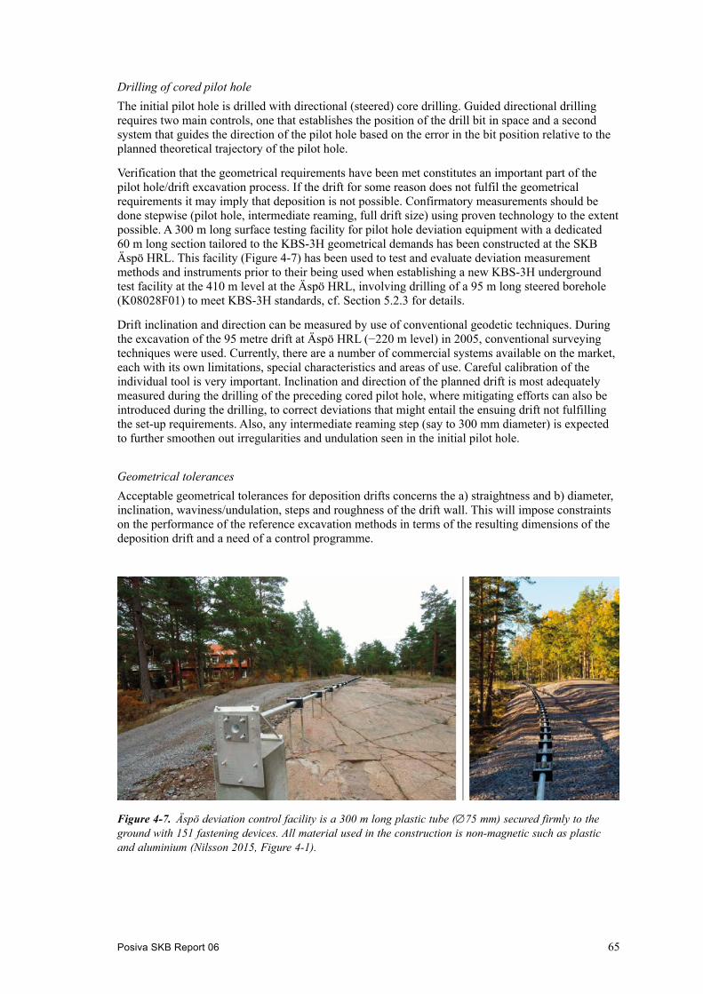
Posiva SKB Report 06 65
Drilling of cored pilot holeThe initial pilot hole is drilled with directional (steered) core drilling. Guided directional drilling requires two main controls, one that establishes the position of the drill bit in space and a second system that guides the direction of the pilot hole based on the error in the bit position relative to the planned theoretical trajectory of the pilot hole.
Verification that the geometrical requirements have been met constitutes an important part of the pilot hole/drift excavation process. If the drift for some reason does not fulfil the geometrical requirements it may imply that deposition is not possible. Confirmatory measurements should be done stepwise (pilot hole, intermediate reaming, full drift size) using proven technology to the extent possible. A 300 m long surface testing facility for pilot hole deviation equipment with a dedicated 60 m long section tailored to the KBS-3H geometrical demands has been constructed at the SKB Äspö HRL. This facility (Figure 4-7) has been used to test and evaluate deviation measurement methods and instruments prior to their being used when establishing a new KBS-3H underground test facility at the 410 m level at the Äspö HRL, involving drilling of a 95 m long steered borehole (K08028F01) to meet KBS-3H standards, cf. Section 5.2.3 for details.
Drift inclination and direction can be measured by use of conventional geodetic techniques. During the excavation of the 95 metre drift at Äspö HRL (−220 m level) in 2005, conventional surveying techniques were used. Currently, there are a number of commercial systems available on the market, each with its own limitations, special characteristics and areas of use. Careful calibration of the individual tool is very important. Inclination and direction of the planned drift is most adequately measured during the drilling of the preceding cored pilot hole, where mitigating efforts can also be introduced during the drilling, to correct deviations that might entail the ensuing drift not fulfilling the set-up requirements. Also, any intermediate reaming step (say to 300 mm diameter) is expected to further smoothen out irregularities and undulation seen in the initial pilot hole.
Geometrical tolerances Acceptable geometrical tolerances for deposition drifts concerns the a) straightness and b) diameter, inclination, waviness/undulation, steps and roughness of the drift wall. This will impose constraints on the performance of the reference excavation methods in terms of the resulting dimensions of the deposition drift and a need of a control programme.
Figure 4‑7. Äspö deviation control facility is a 300 m long plastic tube (∅75 mm) secured firmly to the ground with 151 fastening devices. All material used in the construction is non-magnetic such as plastic and aluminium (Nilsson 2015, Figure 4-1).

66 Posiva SKB Report 06
The tests at the Äspö Hard Rock Laboratory have successfully demonstrated the feasibility of push-reaming technology over a 100 m length scale. Drilling of the steered cored pilot hole (K08028F01) over the same length scale with fulfilment of the set-up geometrical tolerances has also been demonstrated, cf. Section 5.2.2. A corresponding successful outcome relative to stipulated geometrical requirements has been achieved also during steered drilling of a 300 m long cored pilot hole (PH-28) at depth in Posiva’s ONKALO facility, cf. Section 5.2.3.
A successive diameter change (reduction) is expected during the course of the reaming to final diameter due to wear of the periphery cutters. For a 300 m long drift, it is envisaged that the demands placed on the minimum (and maximum) diameter of the drift will result in the need of careful monitoring of the wear of the cutters, and timely exchange of cutters during of reaming (the latter which is anticipated to introduce steps in the drift wall).
Concerning the smoothness of the drift, the reamer head manufacturers have no documented experience how fulfilment may be affected by the reamer head design, say using six instead of four peripheral cutters. Furthermore, there are no data available on the marginal extra overbreak that is generated beyond the extent of the periphery cutters. In conclusion, it has to be optimised how to design the reamer head and how to operate the equipment to minimise generation of grooves and steps.
Water control and acceptable inflowGrouting of deposition drifts can be considered as a viable means to reduce groundwater inflow as long as the outcome is compatible with the long-term safety design basis. This implies that a super-container section must neither be positioned in a grouted section, nor be intersected by fractures in which grouting material has been observed or in which there are indications of grouting. No grouting holes are allowed to be drilled outside the drift profile (Posiva 2016a). The grouting agent employed needs to be approved.
The groundwater flow out of the deposition drift during its operational period must not be high enough to affect the installation of engineered components. Either pre-grouting in the pilot hole or post grouting using a Mega Packer (Eriksson and Lindström 2008) will be used to limit substantial water inflow into the drift, where required. Drift sections with high water inflows will be post-grouted with colloidal silica employing the Mega-Packer, projected to provide a longevity which is in parity with the operational time of the repository. The same requirement regarding approval of grouting agent applies also to pre-grouting in the pilot hole, i.e. only the use of non-cementitious grout is allowed.
Development of EDZ when employing full face excavation techniquesIt is stipulated that the contribution from EDZ to the connected effective transmissivity in deposition holes (3V) and deposition drifts (3H) must be limited. This is achieved by employing full-face reaming techniques combined with a careful drilling procedure. No quantitative measure for a limiting transmissivity of the EDZ has been proposed for the KBS-3H deposition drifts.
The full-face drilling method can be expected to create only minor damage to the surrounding rock walls. The resulting connected effective transmissivity after excavation will therefore largely be governed by the connected transmissivity of natural fractures that intersect the deposition drifts and the less likely occurrence and intensity of spalling.
Control programmeCurrently there is no reliable method that can quantify the connected effective transmissivity of the annular zone of EDZ along the drifts. Geophysical techniques have been used to characterise EDZ, however, none of these are by themselves sufficient for assessing the intensity and extent of the EDZ, nor for characterizing its hydraulic properties. Tentatively it is foreseen that the deposition drifts conform to the design basis for the connected effective transmissivity if they conform to the conditions for acceptable inflow (SKB 2010f).

Posiva SKB Report 06 67
A visual inspection of the completed deposition drift is necessary in order to rule out the occurrence of spalling. Should localised spalling occur, the potential to conform to the design basis for connected effective transmissivity can be improved by removing loose rock debris on the drift walls (SKB 2010b). This mitigation measure requires that outbreaks are levelled with clay-based material. The final contingency action in case of non-compliance would be to reject and backfill the deposition drift.
4.5.2 Design interfacesThe buffer, the filling components, the supercontainer, the plugs and closure all impose design basis on the underground openings.
In this section and in the 3H Underground Openings Construction report (Posiva 2016c) the focus is on those underground openings that are new or differ relative to those of the KBS-3V repository, as the latter are described in the corresponding KBS-3V production reports, for Posiva and SKB (Posiva 2013b and SKB 2010b, respectively).
The nominal diameter and minimum diameter of the deposition drift are imposed by the nominal design of the supercontainer, the distance blocks and filling components. The allowed deviations in the geometry from the nominal are determined by the allowed variations in the deposition drift geometry. In order to allow reliable installation of the supercontainer and buffer and filling compo-nents according to specification, this implies that the strict geometrical requirements defined for the drifts need to be effectively transferred to the original pilot hole and subsequently fulfilled for the ensuing deposition drift reamed in steps. The supercontainer dimensions and tolerances determining the nominal and minimum diameter and acceptable deviations in deposition drift geometry are provided in Posiva (2016g, cf. Section 3.4 therein) whereas an account of the corresponding require-ments on deposition drift undulation are accounted for in Posiva (2016c, cf. Section 2.3.2 (Table 2-3) therein).
The positioning of plugs in the deposition drift impose that inflow to the plug location is limited and that the strength of the rock is sufficient to resist the forces exerted by the plug. In addition, recesses and devices for anchoring shall be prepared in the underground openings in accordance with the specification of the plug, cf. Posiva (2016f).
The acceptable inflow to the deposition drift during the installation of the supercontainers and distance blocks and filling components is imposed by the operation of the deposition machine, which is working with water cushion techniques (Posiva 2012c, cf. Section 9.8 therein).
The diameter of the deposition drift imposes design basis on the diameters of the plug, the distance and filling blocks, respectively.
The layout of the underground openings, the grouting and rock reinforcement shall be designed so that failures and mishaps in conjunction with the nuclear operation are prevented. Further, the design of the underground openings shall allow activities in the disposal facility to be carried out in a safe and cost-effective way with acceptable impact on the environment and on groundwater levels. With respect to this, limits for the maximum allowed inflow to shafts, rock caverns and tunnels other than deposition drifts will be set, but these will be common with KBS-3V.
4.5.3 Production line interfacesThe construction of the underground openings has interfaces with the production lines of the supercontainer, buffer and filling components, plugs and closure. Common for all these connections are that the inspection, acceptance and preparation (incl. cleaning and measurement of geometry) of the deposition drift prior to installation of the supercontainer, distance blocks, filling components and plugs is performed as part of the construction of the underground openings.
In deposition drifts with rock outbreak or other irregularities it is possible to apply remediation measures by filling such voids with bentonite paste to reinstate the geometry and integrity of the deposition drift wall rock. The determination of the geometry of deposition drift is an important input to the installation of the supercontainer and buffer and filling components, in order to assess

68 Posiva SKB Report 06
the variation in installed buffer density, see Posiva (2016e, cf. Sections 4.2, 5.4.8 and 6.1.4 therein). The required inspections and preparations and how they are carried out are presented by Posiva (2016c, cf. Section 5.2.7 therein).
The required preparations for the plugs in deposition drifts are briefly presented by Posiva (2016c, cf. Section 5.2.5 therein) and Posiva (2016f, cf. Section 6.2.1 therein).
4.6 Repository productionThe KBS-3H Repository Production report (Posiva 2016h) serves as an umbrella KBS-3H overview document of the KBS-3H repository production, apart from providing summaries of the KBS-3H specific production line report, also providing reference to those production reports which are common with KBS-3V.
4.6.1 OverviewThe report first introduces vocabulary and reviews the main differences between Posiva’s and SKB’s implementation of the KBS-3H disposal concept, cf. Section 4.7. This is followed by a summary of the KBS-3H design basis based on Posiva (2016a) including a review of regulatory and legal stipulations. This is followed by a chapter that is accounting for the KBS-3H repository system components, with their respective definitions, purposes and associated safety functions. The con-cluding principal chapter reviews the respective production lines with design and production (line) interfaces. The KBS-3H specific production lines have already been accounted for in the preceding Sections 4.2 through 4.5. In the following Sections 4.6.2 through 4.6.4, the production lines which are essentially generic to both KBS-3V and KBS-3H, i.e. the spent nuclear fuel, the canister and closure, are accounted for in brief.
4.6.2 Spent nuclear fuelThe main parts of the spent nuclear fuel line are illustrated in Figure 4-2. The spent nuclear fuel line starts with the delivery of the spent nuclear fuel assemblies to the interim storage facility and encapsulation plant and ends when the spent nuclear fuel assemblies are finally placed in the canister, cf. Section 4.6.3, and the steel lid is finally put on the cast iron insert. Details are given in the SKB and Posiva spent nuclear fuel reports, SKB (2010b) and Raiko et al. (2012), respectively.
4.6.3 CanisterThe main parts of the canister production line are illustrated in Figure 4-2, see also Section 2.3 for KBS-3H related design basis. The canister production line starts with the ordering, manufacturing and delivery of components for the cast iron insert and copper shell and ends when the canisters are installed in the supercontainer, cf. Section 4.3. The KBS-3H production line for the canister is assumed to be the same as for KBS-3V. Details on all stages are given in the Posiva and SKB canister production reports, Raiko et al. (2012) and SKB (2010c), respectively.
4.6.4 ClosureThe main parts of the closure production line are illustrated in Figure 4-2, see also Section 2.7 for KBS-3H related design basis. At this stage of development only preliminary designs of the closure are indicated and for the production only overviews of important tasks for the closure of the different kinds of underground openings are available. For tunnels and shafts below a certain depth, a similar concept as for the backfill in the deposition tunnels of the KBS-3V disposal concept (cf. SKB 2010d, e, Luterkort et al. 2012, Sievänen et al. 2012, Keto et al. 2013), is anticipated and the closure production line will hence show similarities to the KBS-3V backfill production line. Many parts of the disposal facility (e.g. the access tunnel and shafts) will be identical for both KBS-3V and KBS-3H, cf. Figure 1-1, the main difference being the KBS-3H deposition drift and the associated deposition niche at the entrance of the respective drift. In the case of SKB’s implementa-tion, the niche will be excavated between a drift and the main tunnel, whereas in Posiva’s case the

Posiva SKB Report 06 69
niche will connect two parallel central tunnels at the locations for two opposite drifts. It is currently assumed to be backfilled with the same clay material as the main/central tunnels. Another difference between the KBS-3V and KBS-3H closure is that the total main/central tunnel length involved may be greater in the case of KBS-3H. The resulting increase in the number of deposition drifts required will consequently increase the total length of central tunnels to be backfilled. It is also noted that the backfilling of the cylindrical drift entrance section, i.e. the first 10 m or so in each deposition drift (between the drift plug and the deposition niche), is also considered as being part of the closure (Posiva 2016a, cf. Section 3.1 therein).
4.7 Principal difference between Posiva and SKB applications of the KBS-3H disposal variant
The differences between Posiva and SKB application of the KBS-3H disposal variants are accounted for in detail in the respective production line reports. In the following, the main principal differences are outlined for reference. It should be noted that from SKB’s part the design is mostly at a conceptual level and it contains some assumptions. More development work is therefore needed in the future.
4.7.1 Underground openings design basisNominal (centre to centre) horizontal distance from deposition drift to another (drift spacing) is 25 m in Olkiluoto and 30 or 40 m (30 m preferred in terms of utilisation) in Forsmark (SKB 2012).
The repository shall have sufficient capacity to store 4,500 canisters (Posiva) and 6,000 canisters (SKB 2012). The assumed number Posiva’s canisters is the same as was used in the TURVA-2012 safety case (Posiva 2012b), to allow comparison with its results.
4.7.2 Rock engineeringSKB’s design differs from that of Posiva in that SKB employs a single main tunnel whereas Posiva employs a system with dual central tunnels (20 m nominal rock mass between). In SKB’s concept, the deposition niche is excavated between the main tunnel and the planned drift whereas in Posiva’s case the niche is usually excavated between the dual tunnels so that the drift starts from the bounding central tunnel, see Figure 3-1. In some cases, when there is no room in the layout for two opposite drifts, a niche design similar to SKB’s (one excavated between the drift and the central tunnel) can also be used by Posiva.
4.7.3 Supercontainer design basisThe Posiva canisters come in three different lengths (L= 3.552, 4.752 and 5.223 m, respectively) with variable supercontainer lengths accordingly, cf. the supercontainer production report (Posiva 2016d). The SKB canisters, however, only come in one length (L= 4.835 m) which entails that the corresponding supercontainers also come in one size.
4.8 Disposal facility descriptionThe purpose of the facility description is to provide a specific summary of the components and scope of Posiva’s KBS-3H disposal facility at Olkiluoto. The facility description is based on the corresponding description of a KBS-3V disposal facility and considers the specific design character-istics of the KBS-3H disposal facility. The facility description depicts the foreseen disposal facility and its operation at the time when disposal of spent nuclear fuel commences in Olkiluoto in 2020s.
According to a decisions-in-principle made by the Finnish government, the spent nuclear fuel from the Loviisa and Olkiluoto nuclear power plants is permitted to be disposed of at depth in the bedrock in Olkiluoto.

70 Posiva SKB Report 06
The nuclear facilities consist of an underground disposal facility including other aboveground buildings and surface structures serving the facility (NB. an encapsulation plant is part of the nuclear facilities but is not included in the current description). The spiral access tunnel and the ventilation shafts to the underground disposal facility and some auxiliary rooms were constructed as a part of the construction of the ONKALO underground rock characterisation facility during 2004–2016. The construction works needed for the actual repository start after obtaining the construction license. The operating phase is expected to commence in the early 2020s, after obtaining an operating license. Additional deposition drifts and central tunnels are excavated successively, as the disposal work proceeds.

Posiva SKB Report 06 71
5 Design related studies and demonstrations
With respect to design related studies the main focus has been to gain information regarding the initial swelling behaviour of the bentonite buffer and swelling pressure development in both dry and wet drift conditions. This has been done in five tests (scale 0.43), Big Bertha, BB2, BB3, BB4 and BB5. A scale test of the transition zone has also been performed to demonstrate the expected effect reducing the swelling pressure against the drift plug.
With respect to full scale demonstrations four main experiments have been carried out. The Multi Purpose Test which is a shortened (one supercontainer) full scale demonstration of the KBS-3H reference design, DAWE, integrating all main KBS-3H components in an installation at the −220 m level at the Äspö HRL. The second part was the development of a new test site a repository level at the Äspö HRL including a new niche and assessment of the capability of steered core drilling to fulfil the KBS-3H requirements over a 100 m length scale. The 100 m pilot hole also provides a location for a possible future drift. The third part was bringing the experience from the steered core drilling operations at the Äspö HRL to ONKALO and drill a 300 m long pilot hole according to the KBS-3H requirements at that site. The fourth full scale experiment was a supercontainer heater test designed to assess the influence of heat on the buffer during storage and prior to DAWE. It comprised a full scale assembly of a supercontainer with a heated canister followed by monitoring, sampling and analysis.
5.1 Design related studies5.1.1 Development of swelling pressure of the buffer (BB2–BB5 tests)Big Bertha is a half scale test with a supercontainer inside a test cell and water injection/de-airing tubes. The main purpose of the Big Bertha tests BB2 and BB3 was to investigate the buffer swelling from a supercontainer (BB2) and from a distance block (BB3) at extreme conditions, i.e. if a swelling pressure is developed against the rock walls also when no additional water is available from the rock. Only the artificially filled water was available and could contribute to the swelling pressure build up. This question is of importance since the emitted heat from the canisters may cause thermally induced spalling (brittle failure induced by thermally-induced tangential stresses occurring in the drift walls) of the surrounding rock walls. It is believed that a certain counter pressure, i.e. swelling pressure from the bentonite, can prevent spalling from occurring. The results from earlier tests indicate that a swelling pressure will be developed also under these conditions (dry drift) but the uncertainties regarding the magnitude of the swelling pressure is large (Kristensson et al. 2017). No heaters are used in any BB tests.
A test equipment (Big Bertha) was manufactured in 2003 in order to perform large scale bentonite tests within the KBS-3H design, simulating the performance of the buffer in the supercontainer and distance block. The original plan was to perform a long term homogenisation test, where the bentonite after installation and water filling should have access to additional water from filters placed on the “rock” wall. These filters are illustrated by the white areas in the principle drawing, see Figure 5-1 (Kristensson et al. 2017).
The entire test equipment consists of two sections; one with a length of 1 050 mm and the other with a length of 350 mm. In the original design the sections are to be mounted together into one unit confined with lids at both ends. The longer section was intended for a supercontainer unit and the shorter for a distance block with no supercontainer (Kristensson et al. 2017).

72 Posiva SKB Report 06
The two units have been used separately in the two tests, BB2 and BB3 (Kristensson et al. 2017).
1. BB2. This test simulated a drift section including a supercontainer that was filled up according to the DAWE design. The longer section of the Big Bertha test equipment was used as a test cell in this test.
2. BB3. This test simulated a distance block section that was filled up according to the DAWE design. The shorter section of the Big Bertha equipment was used as a test cell in this test (Kristensson et al. 2017).
Two additional steel lids were manufactured. With access to these extra lids it was possible to run two tests at the same time and by that save a lot of time. Both tests simulated a dry case i.e. no additional water was available from the rock mass after having filled up the gaps artificially. Tap water was used for the artificial water filling in both tests (Kristensson et al. 2017).
BB2 testThe bentonite blocks used in the BB2 test were MX-80 Wyoming bentonite from a batch delivered to SKB during 2012. The blocks were compacted with a pressure of 70 MPa with the as-delivered material which had a water content of between 10.5 to 10.7 %. Two inclined boreholes were drilled in each of the blocks in order to facilitate the lifting. The holes had a diameter of 25 mm and a depth of approx. 300 mm. In conjunction with the manufacturing, the block dimensions and achieved density after compaction were determined. During transports and between manufacturing and processing the blocks were wrapped in double plastic covers in order to prevent them from drying and from moisting, depending on air relative humidity (Kristensson et al. 2017).
During the test assembling, block weights and block heights were determined again and based on these figures the bulk density of the blocks were calculated. It was noticed that the blocks had expanded somewhat and therefore the calculated densities were somewhat lower than what had been determined earlier; 2 106−2 140 kg/m3 determined in conjunction with manufacturing and machining vs. 2 058−2 072 kg/m3 determined in conjunction with the test assembly (Kristensson et al. 2017).
Figure 5‑1. Schematic drawing of the “Big Bertha” test equipment (Kristensson et al. 2017).

Posiva SKB Report 06 73
One of the most important outcomes from this test was the radial swelling pressure development. Four load cells in total were installed in radial direction and a fifth load cell was installed to register the total pressure in axial direction. Two pore pressure sensors were also connected, one at the water inlet valve and one at the de-airing valve. The temperature of the test cell was logged and the temperature and relative humidity of the room was registered in order to monitor the surrounding climate (Kristensson et al. 2017).
The test was assembled at the Department of Structural Engineering at the Technical University of Lund. The premises are suitable for this kind of heavy equipment since an overhead crane is required for the handling of all the heavy components in the test. The overhead crane was required to perform both the assembly and the dismantling of the test equipment (Kristensson et al. 2017).
At the start of the test, tap water was injected through a tube with approx. five metre water pressure (0.5 bar). To avoid trapped air in the test cell the inlet/de-airing end was slightly elevated so that the point where the de-airing valve was connected would be in the highest location. Both valves were closed immediately when water emerged from the de-airing valve. The total time for the water filling was about 4 hours. During this time 120.9 litres of water was injected, i.e. the average inflow rate was approx. 0.5 L/min. The available volume of the SC-rock gap was calculated to 119.53 litres. The difference between the injected volume and the available volume was then 1.37 litres. This is most likely explained by water uptake in the bentonite during the four hours of fill-up (Kristensson et al. 2017). After closing the inlet and de-airing valves the pore pressure increased directly (Kristensson et al. 2017).
Upon dismantling, a total of 582 samples were taken from the bentonite and analysed for water content and density (Kristensson et al. 2017).
The radial total pressures were quite different in the two cross sections chosen for measurements and therefore information regarding the bentonite condition in these positions was very interesting. Figure 5-2 shows how the water content varies in the SC-rock gap in all four positions. In the outermost parts of the SC-rock gap, cross section C has the clearly highest water content. There was much less difference in water content closer to the supercontainer shell (Kristensson et al. 2017).
Figure 5‑2. Water content in the samples taken at radial total pressure measurement positions in the supercontainer-rock gap (Kristensson et al. 2017).

74 Posiva SKB Report 06
An obvious correlation was seen between dry density closest to the cell wall and swelling pressure. The sample from the axial total pressure measurement had a degree of saturation of 75.9 %. Fully saturated MX-80 with this dry density is expected to generate a significantly higher swelling pressure (Kristensson et al. 2017).
Much effort was put in providing a good overview of the water content and dry density distribution over the cross sections selected for analysis. Profiles were plotted with water content, dry density and degree of saturation as a function of the radial distance from the test cell wall (Kristensson et al. 2017).
“Muffins” were formed from the bentonite being extruded out through the perforations in the super-container shell. When the extruded bentonite reached the test cell wall the “top” part of the extruded bentonite was forced to expand in perpendicular direction. The result from this was the “muffin” shaped structure observed at test dismantling (Kristensson et al. 2017).
In spite of some test problems the BB2 test was very successful. The registered data shows that almost immediately after the test start, a radial pressure started to be built up at all four measured positions. During the first 80 days after test start a positive water pressure was registered. The water pressure increased in the beginning of the test up to a maximum of 65 kPa after approx. 2 days but had after 80 days decreased to zero (Kristensson et al. 2017).
BB3 testThe test equipment consisted of the shorter section of the BB equipment (Figure 5-1). The bentonite block was manufactured in an almost identical way and with the same MX-80 bentonite as the blocks used in BB2, but there were some different features. The distance blocks are designed to have a lower dry density and higher water content. The raw material was therefore mixed to a water content of 21.4 % and compacted with the same compaction pressure as the bentonite blocks inside the SC. The bulk density of the distance block is similar to the bentonite blocks inside the super container, but since the water content is higher, the dry density is lower (Kristensson et al. 2017).
Out of 315 planned samples, 310 were successfully taken and analysed for water content and density (Kristensson et al. 2017).
The pore pressure was zero at dismantling so the total pressure can therefore be considered entirely as swelling pressure. The radial swelling pressures at the SC-rock gap were quite similar at test dismantling, but the registered swelling pressure in the bottom was slightly higher. Figure 4-13 shows the water content of the samples taken at the radial total pressure measurement positions. The dry density was somewhat higher in the bottom sample, which was expected due to the slightly higher swelling pressure (Kristensson et al. 2017).
Much effort was put into making a good overview of the water content and dry density distribution over the cross sections selected for analysis. Profiles have been plotted showing water content, dry density and degree of saturation as a function of the radial distance from the test cell wall (Kristensson et al. 2017).
The pressure behaviour of the BB3 test was rather similar to BB2 (Figure 5-4 and Figure 5-5). Immediately after having filled up the gaps with water and closed the valves, the water pressure started to increase. The maximum water pressure, approx. 45 kPa, was reached after 30 days (Kristensson et al. 2017).
The two tests (BB2 and BB3) were considered to give important information regarding the swelling behaviour and swelling pressure development when installing supercontainers and distance blocks according to the KBS-3H design in dry deposition drifts. The tests also showed that there would be a certain pressure build up against the rock walls also at these conditions, which is considered to be favourable in order to prevent thermal spalling of the rock wall. It is, however, not known if the achieved pressures are high enough in order to prevent spalling from occurring (Kristensson et al. 2017). As was concluded in the previous project phase (SKB 2012), the DAWE design may produce sufficient swelling pressure to mitigate the thermally induced spalling of rock.

Posiva SKB Report 06 75
Figure 5‑3. Water content for the samples taken at the radial total pressure measurement positions plotted versus the radial distance from the test cell wall (Kristensson et al. 2017).
Figure 5‑4. Radial total pressure and pore pressure data plotted versus time (BB2). The temperature of the test cell is also included in the figure (Kristensson et al. 2017).

76 Posiva SKB Report 06
BB4 testThe main objective of the BB4 test was to investigate the buffer swelling in a drift section including a supercontainer where the installation had been performed according to the DAWE design in a drift with water freely available from the rock matrix, i.e. the remaining voids were artificially filled with tap water after installation and the bentonite has after that had access to additional saline water (salinity of 1 %) from the rock matrix (Kristensson et al. 2017).
The test was intended to provide important information for the full scale regarding a number of issues connected to the artificial water filling and the bentonite swelling behaviour during the first six months. Important issues to be studied were e.g. the early water uptake rate, the bentonite swell-ing into the SC-rock gap and how it would be influenced by the perforation of the SC shell and the radial pressure build up against the rock wall. The test results were also intended to provide a basis for predictions regarding the behaviour of the buffer in the full scale MPT (Multi Purpose Test) test running at Äspö HRL (Kristensson et al. 2017).
The following comments and conclusions were made from the results of the BB4 test:
• During the three first days, approximately 1.6 litres of water were pushed out from the test cell. Since it was an open system, this was the result of the early swelling of the bentonite. The test design deviates from the real conditions, where there probably will be a high backpressure in the rock preventing water outflow from the drift. In a closed system there will instead be a pore pressure build up (see e.g. results from the BB2 test).
• In order to ensure that the water saturation continued without any problems with air trapped in the filters day 45, the water pressure was increased to 200 kPa and at day 48 it was increased to 400 kPa until test termination at day 182.
• The test was believed to represent well the swelling behaviour of bentonite through a perforation in the SC shell in the short term for the real conditions. The gap widths and initial densities of the blocks were close to what is planned to be used in the full scale.
Figure 5‑5. Pore pressure and radial total pressure plotted versus time (BB3). The temperature of the test cell is also included in the figure (Kristensson et al. 2017).

Posiva SKB Report 06 77
• The test design included two radial pressure measurements. Both sensors have reacted distinctly on changes in the applied water pressure, which indicate proper performance. However, none of them have registered any swelling pressure (difference between measured total pressure and applied pore pressure). The explanation for this is that both sensors have been positioned between perforations. Although the SC-rock gap has been completely filled with saturated bentonite, the density in the volumes just outside of sections of solid SC shell has been too low, between 300 and 600 kg/m3, to register any swelling pressure. The investigations of material from the SC-rock gap have shown that the variation in water content and density is high and completely dependent on the position in relation to the SC perforation pattern.
• The degree of saturation was assessed to be 100 % for all samples taken from the SC-rock gap even if there was a certain variation in the results. The degree of saturation decreased then almost linearly over a length of approximately 150 mm (50−200 mm from the test cell wall) down to the initial value in the block. The innermost 100 mm of the block (300−400 mm from the test cell wall) was almost unaffected.
The BB4 test was considered to have given important information regarding the swelling behaviour and swelling pressure development around a supercontainer when there is access to additional water from the rock. The test showed that the SC-rock gap would be filled with swelling bentonite rather soon after installation. The variation in density of this material would, however, be strong and consequently also the swelling pressure acting on the rock.
The other test BB5, is planned to be terminated after the current project phase when fully saturated. The results from these two tests will give important information regarding the water uptake, swelling and homogenisation of the bentonite in a supercontainer in KBS-3H disposal (Kristensson et al. 2017). BB5 mainly aims at providing a possibility to study the final state of the buffer within a supercontainer section when supplied with water at the drift rock wall. The final state is here defined as when the test has come to equilibrium; water does not flow into the test cell and the monitored pressures are constant. The test will provide information about the final state of the buffer which can be used for testing models simulating the KBS-3H system (Kristensson et al. 2017, Section 1.2).
It should be noted that the geometry and the temperature in a real repository differ from the test conditions. The difference in geometry is not expected to affect the results in a full scale repository compared with the BB4 test significantly due to the short test period. Due to the thermal induced heat that dries the inner parts of the bentonite blocks, a radial temperature gradient will be developed that dries the inner parts of the bentonite blocks. This will increase the radial water content gradient and it may also cause cracking of the bentonite blocks, which may influence the wetting evolution (Kristensson et al. 2017).
5.1.2 Transition zone testThe main objectives of the Transition zone laboratory test (Kristensson et al. 2017) was to investi-gate the swelling pressure build up and the maximum pressure that will act on the drift plug after homogenisation and to determine the length of the transition zone to where the density is unchanged. In addition, the results are used to evaluate analytical and numerical models of the processes involved.
The test simulated − in the scale 1:10.8 − the transition zone in contact with a plug including a pellet filling close to the plug and transition blocks and a part of the distance block section. The test was wetted according to the DAWE design and left to saturate and homogenise with water from a radial filter simulating the rock surrounding the bentonite. Swelling pressure and water uptake were measured during the test and after full saturation and completed homogenisation the test was dismantled and carefully sampled.

78 Posiva SKB Report 06
The following comments and conclusions resulted from studying the TZH test (Kristensson et al. 2017, Section 6.3):
• The bentonite blocks underwent an initial homogeneous axial swelling of 2−3 %. This was probably caused by water flowing along block joints during the initial wetting when the friction between the blocks and surrounding tube still was insignificant.
• After the initial axial swelling of a few percent, half of the buffer did not show any additional swelling during the test. The length of this “unaffected zone” corresponds to what the analytical model gives using a friction angle of 10° between the bentonite and the surrounding filter.
• The decrease in density between the unaffected zone and the simulated drift plug, governed by the swelling of the blocks, compression of the pellet filling and friction against the wall, agreed well with the analytical model when using a friction angle of 10°.
• The swelling pressure acting on the “drift plug” was however higher than that obtained when using 10° in the analytical model and in better agreement when using 5°.
The main conclusion of the test is that the transition zone has the expected effect reducing the swelling pressure against the drift plug. Experimental data and analytical calculations using a friction angle between the bentonite and the rock between 5° and 10° are in fair agreement. The conditions and stress evolution are however more complicated than represented by the analytical model. It is therefore proposed to perform a numerical simulation of the system in order to better understand the processes and results (Kristensson et al. 2017, Section 6.3).
5.2 DemonstrationsEarlier KBS-3H projects (SKB 2012) have focused on equipment and component specific tests, such as the development of a deposition machine, reaming of a drift, plug and buffer tests etc. In the KBS-3H System Design Phase the key components have been integrated together at a sub-system level in a test named the Multi Purpose Test (MPT), Section 5.2.1. Additionally, focus has been on demonstrating that 300 m long pilot holes can be drilled in accordance with the KBS-3H require-ments, Sections 5.2.2−5.2.3. A full-scale demonstration of the buffer behaviour when a hot canister is installed inside a supercontainer has also been carried out, Section 5.2.4.
Figure 5‑6. Schematic drawing of the test layout. The inner half (left 500 mm) is called the “distance block section” and the outer half (right 500 mm) is called the “transition zone section” (Kristensson et al. 2017, Figure 5-1).

Posiva SKB Report 06 79
The MPT, Section 5.2.1, and the drilling of K08028F01, Section 5.2.2, was part of the LucoeX project receiving funding from the European Unions European Atomic Energy Community’s (Euroatom) FP7 under grant agreement n° 269905, the LucoeX project.
5.2.1 Multi Purpose Test (MPT)The Multi Purpose Test (MPT), cf. Figure 5-7, implemented at the Äspö HRL is aimed at demon-strating that full scale KBS-3H components can be installed underground. The focus of the test has been on component manufacturing, drift characterisation and preparations, assembly and installation of the components. The test is non-heated and it is installed in the innermost parts of the 95 m drift, DA1619A02, according to the KBS-3H reference design DAWE.
The MPT’s main objectives are:
• Test the system components at full scale and in combination with each other to obtain an initial verification of design implementation and components function.
• This includes the ability to manufacture full scale components, carry out installation (according to DAWE) and monitor the initial system state of the MPT and its subsequent evolution.
The MPT test, besides belonging to KBS-3H project, was also part of the LUCOEX-project (ended in 2015), which had an overall objective to demonstrate, in situ, the technical feasibility of safe and reliable construction, component manufacturing, disposal and sealing of geological disposal facilities through a number of proof-of-concept installations (Gugala et al. 2015).
One of the key components included in the MPT is the supercontainer. The reference design includes a titanium shell but a steel version is used in the MPT since it is not possible to study the impact of corrosion products from the shell formed on the buffer in this test. The supercontainer has segmented distance blocks installed around it. The drift is sealed using a compartment plug, with its associated transition zone made up of a transition block and bentonite pellets. The transition block design is the same as the distance block design and it is used to compensate for the loss of buffer density in the section filled with pellets. Further details on the KBS-3H components can be found in KBS-3H Complementary Studies, 2008–2010 (SKB 2012) and in Chapter 3 of the present report.
Multiple sensors are installed to monitor pressure (swelling and pore), moisture, temperature, displacements and possible water leakages through the plug. After test termination, dismantling and sampling of the various components will provide post mortem data on buffer homogenisation. The duration of the test will be determined depending on the evolution of the test itself.
Figure 5‑7. Schematic illustration of the MPT layout. It includes a supercontainer flanked by bentonite distance blocks on both sides and a compartment plug with its accompanying transition zone made up of a section filled with bentonite pellets and a bentonite transition block (Kronberg 2015).

80 Posiva SKB Report 06
Installation of the MPT includes all steps for installing a reference design KBS-3H repository followed by monitoring:
• Drift characterisation and preparations (Kronberg 2015).
• Buffer manufacturing including the design and manufacturing of a new mould (Johannesson 2014).
• Component assembly (Kronberg 2015).
• Deposition of KBS-3H bentonite components (Kronberg 2015, Ojala and Von Numers 2014).
• Drift closure with a compartment plug followed by water filling and air evacuation according to DAWE (Kronberg 2015).
• Monitoring of the early buffer evolution (Pintado et al. 2015, 2017).
The MPT work also includes upgrading and rebuilding of the control system of the deposition machine to ensure a robust deposition sequences for all components (Ojala and Von Numers 2014).
Buffer manufacturing SKB and Posiva have extensive experience in manufacturing of full scale blocks for KBS-3V (Johannesson 2002). However, KBS-3H has a slightly larger diameter of bentonite blocks and a new mould had to be manufactured.
Table 5-1 lists the requirements and the number of blocks that were manufactured for the MPT. Wyoming MX-80 bentonite was used and a material analysis programme was carried out before compaction (Johannesson 2014). Sulphide, total sulphur content (including sulphide) and organic carbon were within the material requirements (Table 2-7). The montmorillonite content was measured at 90 % which is at the high end of the stipulated 75‒90 % requirement.
Table 5-1. Requirements and number of blocks manufactured for the MPT (Johannesson 2014).
Block type No. of blocks
Water content (%)
Dry density (kg/m3)
Outer diameter (mm)
Height (mm) Inner diameter (mm)
Distance/transition/drift end block
27 21 ± 1 1 712 ± 20 1 765 ± 1 485 ± 1
Supercontainer buffer ring block
12 11 ± 1 1 885 ± 20 1 740 ± 1 485 ± 1 1 058 ± 1
Supercontainer buffer end block
4 17 ± 1 1 753 ± 20 1 740 ± 1 428/350 ± 1
Limitations introduced by the facility for compaction (using the uniaxial compaction method) resulted in the maximum height of the blocks being 500 mm instead of the 1 211 mm stipulated in the refer-ence design of the supercontainer rings.
All blocks were manufactured basically according to the pre-set requirements. A few of the blocks had water content immediately below the requirement with densities immediately above requirement. The main reason for this was that there was no possibility to make an extensive test series before making the blocks for the test. However, the deviations were so small that it was not deemed likely to affect the evaluation of the test. It was also deemed that there should be no problems in manufacturing blocks according to the requirements if a more extensive test series is run in the future and compac-tion parameters are optimised.
Pellets for the test were manufactured using an extrusion technique. Further details on material analyses, compaction and results can be found in the working report on the MPT buffer (Johannesson 2014).
Deposition machine The KBS-3H deposition machine which was originally developed during the ESDRED project (www.esdred.info) uses water cushion technology to transport the components inside the deposition drift. Testing prior to the MPT had identified some issues with the machine with components having a tendency to tilt inside the drift.

Posiva SKB Report 06 81
Extensive upgrades to both soft- and hardware were carried out as part of the MPT to enable for deposition cycles with improved automation and higher reliability. A key step in this development was to instrument the machine with additional sensors to measure its tendency to tilt and install a logging system whereby the previously somewhat undefined problems could be investigated and addressed. The control method for deposition could then be enhanced by developing all interacting functions step by step. Further details on the deposition machine work can be seen in the working report on the upgrades to the deposition machine (Ojala and Von Numers 2014).
Drift characterisation and preparation Characterisation of the test section (L=19 m) hosting the MPT components was done by means of small weirs to locate areas of main inflow. The total leakage was measured as 32 L/day with the bulk of the inflow in the innermost part where the supercontainer and the inner distance block were later installed. The test section was also geologically mapped with focus on leakage points. A laser scanning was also carried out.
The plug notch was excavated using a circular rail enabling parallel cuts which produce rock slices that were later broken loose. Further details on the sawing technique are given in Kronberg (2015).
The part of the plug called the fastening ring was placed and casted in the notch. Since the fastening ring is already cast in place during the drift preparations it later allows for a quick plug installation that only required welding.
The location of the drift did not allow for sensor cables to pass, as is usual, via the drift wall to a nearby parallel tunnel. Instead all cabling had to be taken out through the plug. Cut-outs were made on both sides of the drift and piping was installed. To minimise loss of buffer density the cut-outs were largely cast with low pH concrete. Openings were left for the bentonite to swell into and around the pipes to minimise the risk for flow paths between concrete and rock. Figure 5-8 illustrates the instrumented drift prepared for installation. On the top and side walls the total pressure sensors installed in the rock can be seen. There are also pore pressure sensors in the rock.
Figure 5‑8. The drift prepared for installation. The plug’s fastening ring is casted in place approximately at the position of the camera. Some total pressure sensors are marked with red arrows and cable piping with blue arrows (Kronberg 2015, Figure 5.10).
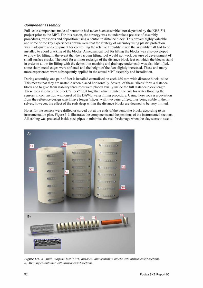
82 Posiva SKB Report 06
Component assembly Full scale components made of bentonite had never been assembled nor deposited by the KBS-3H project prior to the MPT. For this reason, the strategy was to undertake a pre-test of assembly procedures, transports and deposition using a bentonite distance block. This proved highly valuable and some of the key experiences drawn were that the strategy of assembly using plastic protection was inadequate and equipment for controlling the relative humidity inside the assembly hall had to be installed to avoid cracking of the blocks. A mechanical tool for lifting the blocks was also developed to allow for lifting in the event that the vacuum lifting tool would not work because of development of small surface cracks. The need for a minor redesign of the distance block feet on which the blocks stand in order to allow for lifting with the deposition machine and drainage underneath was also identified, some sharp metal edges were softened and the height of the feet slightly increased. These and many more experiences were subsequently applied in the actual MPT assembly and installation.
During assembly, one pair of feet is installed centralised on each 485 mm wide distance block “slice”. This means that they are unstable when placed horizontally. Several of these ‘slices’ form a distance block and to give them stability three rods were placed axially inside the full distance block length. These rods also kept the block “slices” tight together which limited the risk for water flooding the sensors in conjunction with onset of the DAWE water filling procedure. Using these rods is a deviation from the reference design which have longer ‘slices’ with two pairs of feet, thus being stable in them-selves, however, the effect of the rods deep within the distance blocks are deemed to be very limited.
Holes for the sensors were drilled or carved out at the ends of the bentonite blocks according to an instrumentation plan, Figure 5-9, illustrates the components and the positions of the instrumented sections. All cabling was protected inside steel pipes to minimise the risk for damage when the clay starts to swell.
A)
B)
Figure 5‑9. A) Multi Purpose Test (MPT) distance- and transition blocks with instrumented sections. B) MPT supercontainer with instrumented sections.

Posiva SKB Report 06 83
All piping and cabling had to be kept within the periphery of the bentonite component as there is only a 42.5 mm annular gap between the rock and the components. Therefore, a cable block made of metal was placed at the bottom of each component, allowing for protection of the cabling during deposition. The cable block was removed after deposition. As the relative humidity in the assembly hall was optimised for the blocks there were no further surface cracking and the blocks could be lifted using the vacuum tool.
Similar procedures were used for the supercontainer assembly but no rods were needed because the blocks are placed inside the supercontainer shell, Figure 5-9 illustrates the positions of the instrumented sections. Temporary “stiffeners” were used on the outside of the shell to ensure straightness during assembly. Prior to the supercontainer assembly, it was recognised that the current design with end blocks and rings having different water contents (17 and 11 %) means that the relative humidity inside the assembly hall cannot be optimised for the two different types of blocks simultaneously. From a practical handling standpoint, in storage, during compaction and when machining, it would be prefer-able to handle material and blocks with a harmonised water content. This would imply redesigning the buffer blocks in the supercontainer, however, a redesign can only be done if it can be shown to have no negative impact on long-term safety. The heated supercontainer test, Section 5.2.4 successfully tested the possibility to harmonise the water content of the blocks at 14 %.
Installation The MPT installation was carried out from November 14th through to December 7th of 2013 (Kronberg 2015). The components were transported down the Äspö HRL access tunnel one by one to the −220 m level inside a transport tube. The transport tube was placed outside the drift, after which the starting tube with the deposition machine was placed behind it. The deposition machine then ran through the transport tube picking up the component and automatically drove the component to its position inside the drift. Overall the various depositions worked out well and the automated sequence managed most of the control with some manual fine-tuning at the end. A good contact was achieved between the compo-nents, with only a 4 mm difference between the four components’ total length measured at assembly and the overall length of the deposited components, and this is assumed to be within the measurement tolerances. Figure 5-10 illustrates the installed supercontainer, total weight approximately 45 tons. Minor water splashing from the machines water cushion system was noted on the components; how-ever, it did not affect the integrity of the components during the MPT installation. A mechanical upgrade is anyhow recommended for future development in order to avoid the splashing.
When all components had been deposited the compartment plug was installed. Technical details on the compartment plug can be found in Posiva (2016f). The compartment plug installation was undertaken in three main steps: first the collar, which is made up of four steel segments, was welded to the previously installed fastening ring. All cables and pipings were then led through the collar and finally the cap was lifted and welded in place.
The plug installation was followed by installation of pellets through the pellet filling hole in the plug. Even though the plug had been inspected by a certified company, two holes were noted in the weld (pellet dust was seen escaping through a pore) and they had to be re-welded, see continued discussion below. Filling with pellets was followed by contact grouting via two sets of tubes; between the steel and casting and between the casting and rock. Contact grouting was done using colloidal silica grout.
Once this was completed all sensors were connected to the Data Acquisition System (DAS) and checked and monitoring was initiated. The final step of the installation was the DAWE procedure, where water was supplied through the pipes at the bottom of the plug and air evacuated with a long pipe to the top of the drift front. The KBS-3H reference design stipulates that the removal of the pipe is initiated when the water level reaches the highest point and water starts to flow from the air evacuation pipe. However, in this case a slight over-pressure was applied onto the section which allowed func-tional checks of some of the sensors employed in the test. Additional leakages were noted in the plug welds which had to be re-welded again. These leakages have prompted a change of design of the plug which will allow for easier access to welding and inspection of the welds prior to water filling. Another update will be the addition of a drainage pipe at the bottom of the plug; this is needed to avoid water from filling up inside the collar during the plug installation phase before the cap is welded in place and pellets are installed. For details of the suggested updates view Posiva (2016f, Section 3.2).

84 Posiva SKB Report 06
Status of monitoring The test is currently being monitored (2017). Initially it was planned that pre-modelling would enable definition of an appropriate test duration. However, the modelling encountered problems, mainly with conceptualisation of the extrusion of bentonite through the perforated supercontainer shell. As a result of this a date for dismantling will mainly be based on measurements from the actual test and the desired dismantling conditions, this date remains to be decided. Monitoring will be continued until the dismantling, which will take place in the future after the current project phase. The measurements show that the buffer is hydrating and the gap between the blocks and the supercontainer shell, and the host rock is pressurised. The pressure measured by the sensors in drift wall could partially be swelling pressure and partly pore pressure although it is not possible to know in what percentage. The gap between the blocks and the supercontainer shell, and the host rock is probably filled with low density bentonite. It is not possible to conclude anything about the inner gap but it is probably open (capacitive hygrometers and psychrometers at the inner part of the blocks indicates the suction is still high). The BB4 test (see Section 5.1.1) with constant water supply shows that the bentonite fills the gap space. The pore pressure measurements in rock and in gap give positive pressure, so it is possible to expect the same situation in MPT test. At the beginning of the test and due to the high suction of the blocks, a thin layer of rock could have been in unsaturated state but as it has been commented before, the current measures of pore pressure show the rock is saturated.
5.2.2 New KBS-3H test site and steered core drillings at ÄspöThe KBS-3H project has a test site available at the −220 m level at the Äspö HRL, where two deposition drifts have been excavated, 15 m and 95 m long (Bäckblom and Lindgren 2005), with the later being the location of the MPT installation, Section 5.2.1. A new KBS-3H test site is being developed at the −400 m level of the Äspö HRL, TAS08, in the TASU tunnel (Figure 5-11) (Nilsson 2015), hosting boreholes K03009F01 and K08028F01 being the new boreholes discussed in the following sections. The drilling of K08028F01 was similarly to the MPT, Section 5.2.1, part of the LUCOEX-project and partly funded by the EC.
Figure 5‑10. Supercontainer positioned in the drift with all its cables pulled. The tight fit between the supercontainer and drift wall is clearly visible. A small paper has been placed down to the left of the supercontainer to ensure that the deposition machine will detect the supercontainer during deposition of the next component.

Posiva SKB Report 06 85
The new test site allows for demonstration and verification of the performance of pilot borehole drilling techniques with the option of reaming to 1.85 m diameter at repository level. Reaming could be followed by post-grouting using the Mega Packer technique (Eriksson and Lindström 2008). The reaming and the Mega Packer step have been postponed to a future project phase.
The KBS-3H design utilises 300 m long horizontal, slightly upward inclined deposition drifts, with a diameter of 1.85 m. The drifts have strict geometrical requirements, Table 5-2. The earlier drilling operations at the −220 m level at the Äspö HRL did fulfil the requirements over a 100 m length scale (Bäckblom and Lindgren 2005); however, the results indicated that the full-face technique used at that time could have difficulties in fulfilling the requirements over a 300 m length scale. When assessing different techniques for constructing the drifts in 2011, the KBS-3H project concluded that drilling a 76 mm core drilled pilot hole, followed by stepwise reaming of the hole to full drift diameter size had the largest probability of success.
The KBS-3H design thus has high demands on 76 mm pilot core drilling accuracy and steered drill-ing is required. Steered core drilling in turn relies on accurate deviation measurements so that the position of the borehole in the rock can be measured. There are multiple suppliers of tools available for surveying boreholes; however, they have the inherent problem that the quality in the data produced is difficult to verify, simply due to the fact that the holes are not available for independent geodetic control since they are located inside the rock.
Figure 5‑11. Schematic view showing the service tunnel TASU at the Äspö HRL with the connected KBS-3H experimental drift TAS08 and the DETUM-11 niche TAS03. K08028F01 is the new KBS-3H borehole (Nilsson 2015).
1 Detailed investigation methods, SKB’s research and modelling programme (Vidareutveckling av metoder, verktyg och detaljerat program för undersökningar och modellering inför byggstart).
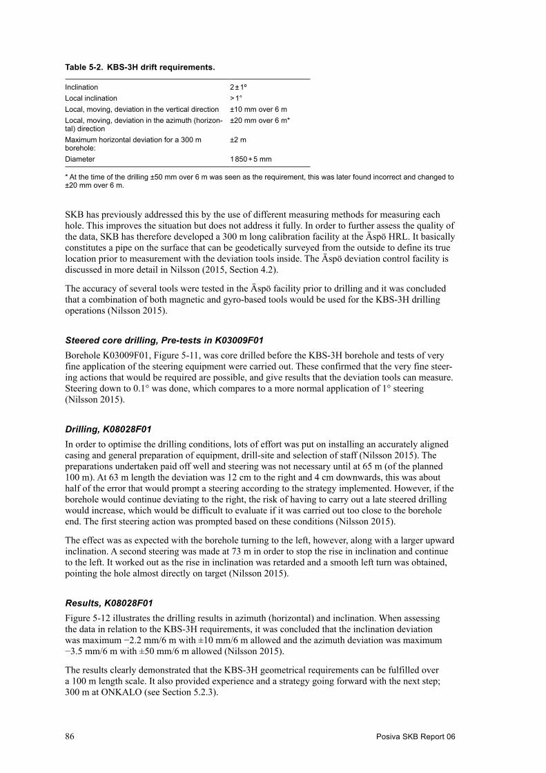
86 Posiva SKB Report 06
Table 5-2. KBS-3H drift requirements.
Inclination 2 ± 1ºLocal inclination > 1°Local, moving, deviation in the vertical direction ±10 mm over 6 mLocal, moving, deviation in the azimuth (horizon-tal) direction
±20 mm over 6 m*
Maximum horizontal deviation for a 300 m borehole:
±2 m
Diameter 1 850 + 5 mm
* At the time of the drilling ±50 mm over 6 m was seen as the requirement, this was later found incorrect and changed to ±20 mm over 6 m.
SKB has previously addressed this by the use of different measuring methods for measuring each hole. This improves the situation but does not address it fully. In order to further assess the quality of the data, SKB has therefore developed a 300 m long calibration facility at the Äspö HRL. It basically constitutes a pipe on the surface that can be geodetically surveyed from the outside to define its true location prior to measurement with the deviation tools inside. The Äspö deviation control facility is discussed in more detail in Nilsson (2015, Section 4.2).
The accuracy of several tools were tested in the Äspö facility prior to drilling and it was concluded that a combination of both magnetic and gyro-based tools would be used for the KBS-3H drilling operations (Nilsson 2015).
Steered core drilling, Pre-tests in K03009F01 Borehole K03009F01, Figure 5-11, was core drilled before the KBS-3H borehole and tests of very fine application of the steering equipment were carried out. These confirmed that the very fine steer-ing actions that would be required are possible, and give results that the deviation tools can measure. Steering down to 0.1° was done, which compares to a more normal application of 1° steering (Nilsson 2015).
Drilling, K08028F01 In order to optimise the drilling conditions, lots of effort was put on installing an accurately aligned casing and general preparation of equipment, drill-site and selection of staff (Nilsson 2015). The preparations undertaken paid off well and steering was not necessary until at 65 m (of the planned 100 m). At 63 m length the deviation was 12 cm to the right and 4 cm downwards, this was about half of the error that would prompt a steering according to the strategy implemented. However, if the borehole would continue deviating to the right, the risk of having to carry out a late steered drilling would increase, which would be difficult to evaluate if it was carried out too close to the borehole end. The first steering action was prompted based on these conditions (Nilsson 2015).
The effect was as expected with the borehole turning to the left, however, along with a larger upward inclination. A second steering was made at 73 m in order to stop the rise in inclination and continue to the left. It worked out as the rise in inclination was retarded and a smooth left turn was obtained, pointing the hole almost directly on target (Nilsson 2015).
Results, K08028F01 Figure 5-12 illustrates the drilling results in azimuth (horizontal) and inclination. When assessing the data in relation to the KBS-3H requirements, it was concluded that the inclination deviation was maximum −2.2 mm/6 m with ±10 mm/6 m allowed and the azimuth deviation was maximum −3.5 mm/6 m with ±50 mm/6 m allowed (Nilsson 2015).
The results clearly demonstrated that the KBS-3H geometrical requirements can be fulfilled over a 100 m length scale. It also provided experience and a strategy going forward with the next step; 300 m at ONKALO (see Section 5.2.3).
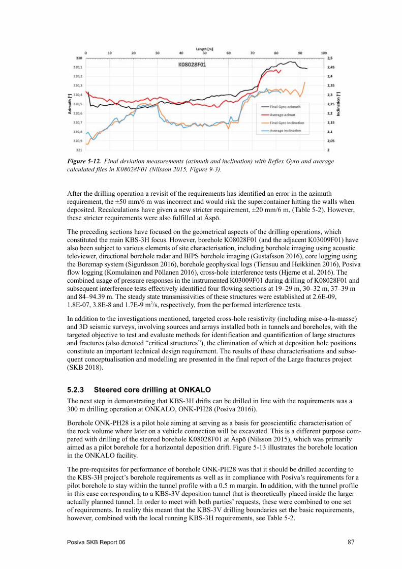
Posiva SKB Report 06 87
After the drilling operation a revisit of the requirements has identified an error in the azimuth requirement, the ±50 mm/6 m was incorrect and would risk the supercontainer hitting the walls when deposited. Recalculations have given a new stricter requirement, ±20 mm/6 m, (Table 5-2). However, these stricter requirements were also fulfilled at Äspö.
The preceding sections have focused on the geometrical aspects of the drilling operations, which constituted the main KBS-3H focus. However, borehole K08028F01 (and the adjacent K03009F01) have also been subject to various elements of site characterisation, including borehole imaging using acoustic televiewer, directional borehole radar and BIPS borehole imaging (Gustafsson 2016), core logging using the Boremap system (Sigurdsson 2016), borehole geophysical logs (Tiensuu and Heikkinen 2016), Posiva flow logging (Komulainen and Pöllanen 2016), cross-hole interference tests (Hjerne et al. 2016). The combined usage of pressure responses in the instrumented K03009F01 during drilling of K08028F01 and subsequent interference tests effectively identified four flowing sections at 19–29 m, 30–32 m, 37–39 m and 84–94.39 m. The steady state transmissivities of these structures were established at 2.6E-09, 1.8E-07, 3.8E-8 and 1.7E-9 m2/s, respectively, from the performed interference tests.
In addition to the investigations mentioned, targeted cross-hole resistivity (including mise-a-la-masse) and 3D seismic surveys, involving sources and arrays installed both in tunnels and boreholes, with the targeted objective to test and evaluate methods for identification and quantification of large structures and fractures (also denoted “critical structures”), the elimination of which at deposition hole positions constitute an important technical design requirement. The results of these characterisations and subse-quent conceptualisation and modelling are presented in the final report of the Large fractures project (SKB 2018).
5.2.3 Steered core drilling at ONKALOThe next step in demonstrating that KBS-3H drifts can be drilled in line with the requirements was a 300 m drilling operation at ONKALO, ONK-PH28 (Posiva 2016i).
Borehole ONK-PH28 is a pilot hole aiming at serving as a basis for geoscientific characterisation of the rock volume where later on a vehicle connection will be excavated. This is a different purpose com-pared with drilling of the steered borehole K08028F01 at Äspö (Nilsson 2015), which was primarily aimed as a pilot borehole for a horizontal deposition drift. Figure 5-13 illustrates the borehole location in the ONKALO facility.
The pre-requisites for performance of borehole ONK-PH28 was that it should be drilled according to the KBS-3H project’s borehole requirements as well as in compliance with Posiva’s requirements for a pilot borehole to stay within the tunnel profile with a 0.5 m margin. In addition, with the tunnel profile in this case corresponding to a KBS-3V deposition tunnel that is theoretically placed inside the larger actually planned tunnel. In order to meet with both parties’ requests, these were combined to one set of requirements. In reality this meant that the KBS-3V drilling boundaries set the basic requirements, however, combined with the local running KBS-3H requirements, see Table 5-2.
Figure 5‑12. Final deviation measurements (azimuth and inclination) with Reflex Gyro and average calculated files in K08028F01 (Nilsson 2015, Figure 9-3).

88 Posiva SKB Report 06
Drilling ONK-PH28The same deviation measurement equipment and drilling strategy (with adapted boundary require-ments) used at Äspö were also adopted at ONKALO. The deviation tools were also supplemented with an additional magnetic tool adapted to be pumped through the drill bit.
Due to time limitations, the casing installation procedure adopted at Äspö could not be fully implemented. After completed casing installation, core drilling in N-size (75.8 mm) to 10.23 m was carried out, before the first deviation measurement with the gyro was conducted. Firstly, the result showed a discrepancy regarding the start inclination between the geodetic measurement, which showed the value 2.0°, and the gyro measurement inside the casing indicating 1.82°. Moreover, as the inclination continued downwards to 1.45° at 9 m, the prescribed limit according to the drilling strategy was overstepped, and a steering upwards had to be started immediately.
Similar steering settings as implemented at Äspö were used; however, these had almost no effect on the inclination as foliated granite counteracts the steering by giving a strong natural tendency down-wards. After a third attempt the inclination could be increased to 1.59° at 25.55 m borehole depth.
A total of 25 steered sections had to be carried out in borehole ONK-PH28. As mentioned, the influence of the physical rock properties (hardness, geometry of discontinuities and foliation) will tend to deviate the borehole from its stipulated path. In borehole ONH-PH28 this natural deviation of the borehole needed many careful steerings before lessons were properly learned. Compared with the lithology at Äspö, the ONKALO gneissic rocks generally demand harder steering settings. For further details on the drilling and steering operations, view Posiva (2016i).
Results, ONK-PH28Figure 5-14 illustrates the drilling results in azimuth (horizontal) and inclination. When assessing the data in relation to the KBS-3H requirements, it was concluded that the inclination deviation was maximum +8.0 mm/6 m with ±10 mm/6 m allowed and the azimuth deviation was maximum −8.2 mm/6 m with ±20 mm/6 m allowed (Posiva 2016i). The results clearly demonstrate that the KBS-3H geometrical requirements can be fulfilled over a 300 m length scale. This has constituted one of the main remaining obstacles for the KBS-3H design and realising the objectives is a significant step for the design.
Figure 5‑13. General location of the ONK-PH28 pilot hole in ONKALO. Start and end locations are marked by black circles. Locations of future deposition tunnels can be seen in the lower left part of the illustration.

Posiva SKB Report 06 89
5.2.4 Heater Test with a SupercontainerNone of the earlier KBS-3H tests (scale tests or full scale tests) have been carried out with heated canisters. However, there is extensive experience on heated conditions from KBS-3V, both from tests and modelling. Recent work has been carried out within the BUSTER (Johannesson et al. 2014), and BÅT projects. The KBS-3V results confirm that the heat emitted from the canister causes a redistribution of water in the buffer blocks surrounding the canister, which can make the buffer crack after a certain time period due to local dryness.
The KBS-3H design differs from KBS-3V in several ways but it has been concluded that the issue regarding redistribution of water in the buffer can be a potential problem also for the KBS-3H design. Cracking of the KBS-3H buffer can risk the integrity of the supercontainer and possibly lead to buffer loss. Buffer fall-out can also disturb the transport, deposition and DAWE air evacuation process.
For KBS-3H the cracking problem may firstly occur between the time the supercontainer is assembled and prior to deposition, which with the current design is assumed to be 10 days at most. Secondly, it may occur during the time period after deposition but prior to water filling of the compartment, which with the current design also equals 10 days at most for the first supercontainer deposited in a drift. The maximum risk period is thus 10 + 10 = 20 days.
To find out how big a problem the drying of the buffer during storage and installation is, a full scale test has been carried out simulating 10 days in storage at room temperature and 10 days in the drift with cooler surroundings. The basic test outlining is presented in Figure 5-15, with a supercontainer placed inside the transport tube.
The heated supercontainer test also assesses a potential new buffer design with harmonised water content in blocks and rings, 14 ± 1 %, compared with the current reference design of 11 ± 1 % rings and 17 ± 1 % blocks, see Section 5.2.1, sub-section Component assembly, for additional details.
Figure 5‑14. Final deviation measurements (inclination and azimuth) with Reflex Gyro and Devishot in ONK-PH28. Some of the rock types prevailing in the ONKALO facility contain magnetite, which explains the disturbances in the magnetically based Devishot data.

90 Posiva SKB Report 06
Pre-modellingThe test was preceded by pre-modelling in order to predict its outcome and to support an instru-mentation plan. A thermal power of 1 700 W was used for the canister. The pre-modelling predicted that very little cracking would happen if the initial canister temperature was below 40 °C. With an initial canister temperature of 80 °C the crack depth was predicted to be approximately 1 cm on the inner side of the buffer rings after 10 days in the transport tube. Given that a KBS-3H repository assembly hall is not designed, an accurate canister starting temperature cannot be defined at this time but the project eventually decided at around 60 °C for the actual test based on the expectation that the canisters will be placed in a transport cask in a repository scenario and that the cask will provide some isolation. If instead placed in open air it would be in the order of 40−45 °C, dependent on ventilation.
The model cannot predict if there are any flow paths for air between the inner gap and the outer gap, i.e. between the canister and the buffer and between the shell and the rock. It has been seen in other tests that there can be leakage between the blocks. Any leakage between the gaps, i.e. air paths between blocks, would increase the drying and therefore also the cracking. Possible thermal stresses from the asymmetric heat distribution were not accounted for in the model used to predict crack depth.
The model also predicted that there would not be much change in the water content distribution in the blocks during the simulated time in the drift with a cooler ‘rock’ surface surrounding the supercontainer, i.e. the water content profiles inside the blocks do not change that much during those 10 days according to the modelling.
InstrumentationBased on modelling and earlier experience, a total of 78 temperature sensors and 8 RH sensors were included in the test. Table 5-3 lists their locations in the test. The sensors were relatively evenly distributed, and Figure 5-16 gives the sensor positions in the rings as an example.
Figure 5‑15. Basic outfling of the Heated Supercontainer test, left figure illustrating the supercontainer assembly and the right figure illustrating the supercontainer placed inside a sealed transport tube in horizontal position.

Posiva SKB Report 06 91
Table 5-3. Heated supercontainer test instrumentation.
Temperature RH
Bottom block, C1 6R2 16R5 16R9 16Top block, C2 6Canister 6Transport tube 12Assembly hall 2Air void between shell and transport tube
6
Sum: 78 8
Assembly and test periodMX-80 bentonite was used and the blocks were compacted in Ystad similarly as the MPT blocks. The bottom block was machined to a height of 350 mm and the top block to 278 mm, both having a dry density of 1 753 kg/m3. The 10 rings had a dry density of 1 885 kg/m3 and were machined to 491 mm. All blocks had a water content of 14 %.
Figure 5‑16. Temperature sensors in ring R5.

92 Posiva SKB Report 06
Given the experiences from the MPT, the assembly was straightforward and with the harmonised water content in both blocks and rings, the air humidity in the assembly hall could be regulated to an appropriate level for all blocks, 63.5 %.
Figure 5-17 illustrates final preparations for the canister lift. The canisters sensors and heaters had to be disconnected during the day when the canister was installed in the supercontainer and turned horizontally, September 26th, 2016. Once the heaters and canister sensors were connected again, in the evening of September 26th the canister temperature had come down from approximately 60 °C to an average of 45 °C with the hottest part, the top of the canister, still at 52 °C at that time. It was also noted that the canister temperature continued to drop a few degrees after the heaters and sensors were connected. This is as expected as the blocks with room temperature cools the canister.
Figure 5-18 illustrates block R5 as an example of the temperature development in the blocks during the test period. It can be seen that the block temperatures equilibrate during the test period. The temperature data follows a logical pattern with the sensors in the buffer closest to the canister show-ing the highest temperature. The effect of the horizontal supercontainer is also evident as the lower sensors show the highest temperature due to the canister leaning on to the buffer on the lower side.
When comparing with the pre-modelling and taking mid-canister with a starting temperature of 40 °C and comparing to ring R5 in the test, the modelled temperatures of the buffer rings is approxi-mately 5−7 °C lower than the test data. The most likely reason for this is that the heat transfer from the transport tube to the surroundings has been overestimated in the modelling.
Cooling was initiated after 10 days, on the 6th of October, however, the cooling equipment malfunctioned and only a very small temperature drop was achieved in the transport tube. A small response can be seen in Figure 5-18. There is also a small increase in the temperature a few days before cooling, on the 4th of October, which origin is currently unknown. The malfunctioning cooling equipment was unfortunate; however, the model predicted limited effects from cooling so the overall test results are still deemed to be good.
Pre-heated canisterSupercontainer with sensor cabling fastened outside
Figure 5‑17. Pre-heated canister being prepared for installation inside the supercontainer.

Posiva SKB Report 06 93
The RH in the air void between the supercontainer and the transport tube climbed quickly above 80 % and evened out around 90 % after approximately 3 days, this compares to 63.5 % which would be expected without the heaters turned on. The RH test data are difficult to compare to the model as the RH in the model varies with the position in the void (being highest close to the transport tube and lowest close to the blocks), the sensors exact position is not that detailed, however they indicate that the transport tube has a fairly even and high RH.
Water accumulating at the bottom of the transport tube was measured, Figure 5-19. 1 161 ml of water was collected during the full test.
The cooling of the transport tube is clearly noted in the amount of water collected. Given that each block contains several hundreds of litres water, the total amount of condensate water is small in comparison. The model predicts somewhat less, however, this is likely related to the thermal bound-ary conditions between the transport tube and the surroundings being somewhat incorrect as seen from the temperature data.
During the test period, a peep-hole camera was used to look underneath the supercontainer, Figure 5-20 illustrates one position on block R8. As can be seen in the photos, minor cracking has started after two days with 1 700 W (left photo), and after 3 days it has increased further (right photo). The photos below are examples from ring R8, but there were cracking on other blocks after 3 days as well. However, even with the cracking the amount of material coming loose from the supercontainer was limited. Once the test was terminated all that loose material was collected and weighed to 4.1 kg wet and 2.2 kg dry. Most of this material had come loose at the end blocks in the form of flaking, see Figure 5-21, possibly due to tension building up against the endplates of the supercontainer. Overall 2.2 kg of dry buffer mass is a small amount of ‘eroded’ material which will not compromise the buffer function. There were no larger pieces either, so the risk of bentonite clogging the gap underneath the supercontainer and possibly compromising the DAWE drainage is most likely small. It should be noted that the material collected was very wet, and have collected condensate water, 1.4 kg, thus the total condensated water is likely closer to 2.6 kg rather than the 1.16 kg collected.
Figure 5‑18. Temperature development in ring, R5.
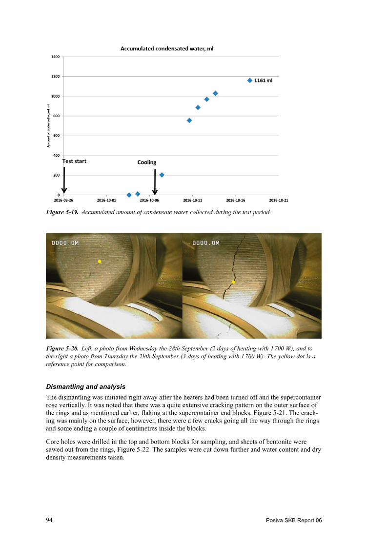
94 Posiva SKB Report 06
Dismantling and analysisThe dismantling was initiated right away after the heaters had been turned off and the supercontainer rose vertically. It was noted that there was a quite extensive cracking pattern on the outer surface of the rings and as mentioned earlier, flaking at the supercontainer end blocks, Figure 5-21. The crack-ing was mainly on the surface, however, there were a few cracks going all the way through the rings and some ending a couple of centimetres inside the blocks.
Core holes were drilled in the top and bottom blocks for sampling, and sheets of bentonite were sawed out from the rings, Figure 5-22. The samples were cut down further and water content and dry density measurements taken.
Figure 5‑19. Accumulated amount of condensate water collected during the test period.
Figure 5‑20. Left, a photo from Wednesday the 28th September (2 days of heating with 1 700 W), and to the right a photo from Thursday the 29th September (3 days of heating with 1 700 W). The yellow dot is a reference point for comparison.

Posiva SKB Report 06 95
Figure 5‑21. Left, cracking pattern on outer surface on the rings, right, flaking on the bottom block, C1.
Figure 5‑22. Taking samples from the buffer rings.

96 Posiva SKB Report 06
Figure 5-23 gives an example of the water content profile in ring R5, downwards and Figure 5-24 illustrates the dry density in the same direction. It can be seen that the surface against the canister has dried to some extent. The outer buffer surface towards the air void, between the supercontainer and the transport tube has also dried but actually more than the inner surface. The model predicted an opposite situation and it is currently not fully explained why the outer surface seems to have dried faster, however, it could possibly be due to the air circulation outside of the blocks.
It should also be noted that there likely are density variations inside the blocks before test start, which actually can look quite similar to the variation seen in Figure 5-24, and future test should include several reference blocks to assess this in more detail.
All measurements in the supercontainer show similar patterns although there is less drying on the outside of the blocks towards the sides and upwards of the buffer (when horizontal). The overall changes in water content are small, which is in line with the model. However the cracking was more extensive in the test than the model had predicted. Cracking is known to be difficult to predict, but the heated supercontainer test has provided additional data for further modelling development.
ResultsThe heated supercontainer test has provided valuable experiences on how the heat from the canister influences the supercontainer buffer during assembly and deposition. It is clear that the buffer will start to dry, however, the changes are limited over the short time periods that are of interest for the KBS-3H design.
It is also clear that the buffer surface will start to crack inside the supercontainer before the DAWE water filling can be carried out, however, the supercontainer shell seems to maintain the integrity of the component very well and the buffer mass loss should not compromise the required buffer densities and the buffer that may fall on to the deposition drift floor will most likely be so limited that it will not clog the drainage underneath the components. If KBS-3H development is continued tests could be carried out where bentonite flakes are dropped in a deposition drift at different water flow rates to assess and ensure that there is no risk of dams building up.
The test has also provided lots of valuable data in support of future model development.
Figure 5‑23. water content data from ring R5, downwards, on the side where the canister leans on the buffer surface.

Posiva SKB Report 06 97
Figure 5‑24. Dry density data from ring R5, downwards, on the side where the canister leans on the buffer surface.


Posiva SKB Report 06 99
6 Long-term safety related studies
6.1 Impact of rock shear on canister6.1.1 GeneralExisting fractures intersecting a KBS-3H deposition drift may be activated and sheared by an earthquake. The effect of such a rock shear has been investigated by Börgesson and Hernelind (2016) using finite element calculations employing the code Abaqus. The buffer material surrounding the can-ister in a deposition drift acts as a cushion between the canister and the rock, reducing substantially the force transferred to the canister by rock shear. The lower density of the buffer also yields a softer material and reduced force on the canister. However, at the high buffer density required for a reposi-tory, the stiffness of the buffer is rather high and may allow transfer of large forces to the canister. The stiffness increases with increasing rate of shear, which means that there may be substantial damage to the canister at very high shear rates (Börgesson and Hernelind 2016, Section 1.2.1).
The effect of rock shear exerted on a canister and buffer in KBS-3V has been extensively investigated for SR-Site and has been reported by Hernelind (2010). The purpose of the work reported here is to model some of the worst cases with respect to stress transfer and to compare the results obtained for the KBS-3H and KBS-3V geometries. The KBS-3V finite element models have been used as the basis for the modelling but the geometry is changed to account for the KBS-3H orientation and the presence of the supercontainer shell. One of the worst cases previously identified for KBS-3V (perpendicular shear case) has been modelled for KBS-3H and the results compared. In addition, the case of compressional shear at a skewed angle has been modelled. The case of skewed compressional shear has not been modelled for KBS-3V, since it was not considered a likely case for KBS-3V, however identified to be possible for KBS-3H (Börgesson and Hernelind 2016, Section 1.2.1).
6.1.2 Results and conclusionsPerpendicular shearThe rock shear has been assumed to take place perpendicularly to the canister and a quarter of the length along the canister (from the top). The shear calculations have been driven to a total shear of 10 cm, although 5 cm corresponds to the reference and dimensioning case. Finally, the results have been compared with the results of an identical rock shear through a KBS-3V deposition hole with identical properties and conditions. The components exposed to the earthquake-induced rock shear consists of the canister insert (made of cast iron), the insert lid (made of steel) and the outer copper canister (including the lid), surrounded by buffer material (bentonite) and the supercontainer shell (Börgesson and Hernelind 2016, Section 3.1.1).
The results for the bentonite buffer show that the buffer is strongly plasticised during the rock shear, which helps protect the canister. When comparing the results with KBS-3V, it is found that the difference in stresses and strains between the two concepts generally is very small, implying smaller stresses and strains in the KBS-3H case than for KBS-3V. The difference is most likely caused by the extra 5 cm of buffer that exists outside the canister in KBS-3H (see Table 3-2) compared with KBS-3V (Börgesson and Hernelind 2016, Section 3.3).
As to the copper canister, the plastic strain is rather high approximately mid-length of the copper shell. The results clearly demonstrate that the effect of rock shear on the stresses in the copper shell is essentially identical for the KBS-3H and 3V situations. Also, with respect to plastic strains in the iron insert, the difference between 3H and 3V is insignificant (Börgesson and Hernelind 2016, Section 3.3).
The perforated supercontainer shell (assumed to be made of steel in this analysis) is, as expected, strongly deformed close to the shear plane but otherwise remains rather unaffected. The plastic strains are so large (20‒200 %) that the supercontainer shell would be broken close to the shear plane. The breaking is not modelled but it is not expected to affect the results (Börgesson and Hernelind 2016, Section 3.3).
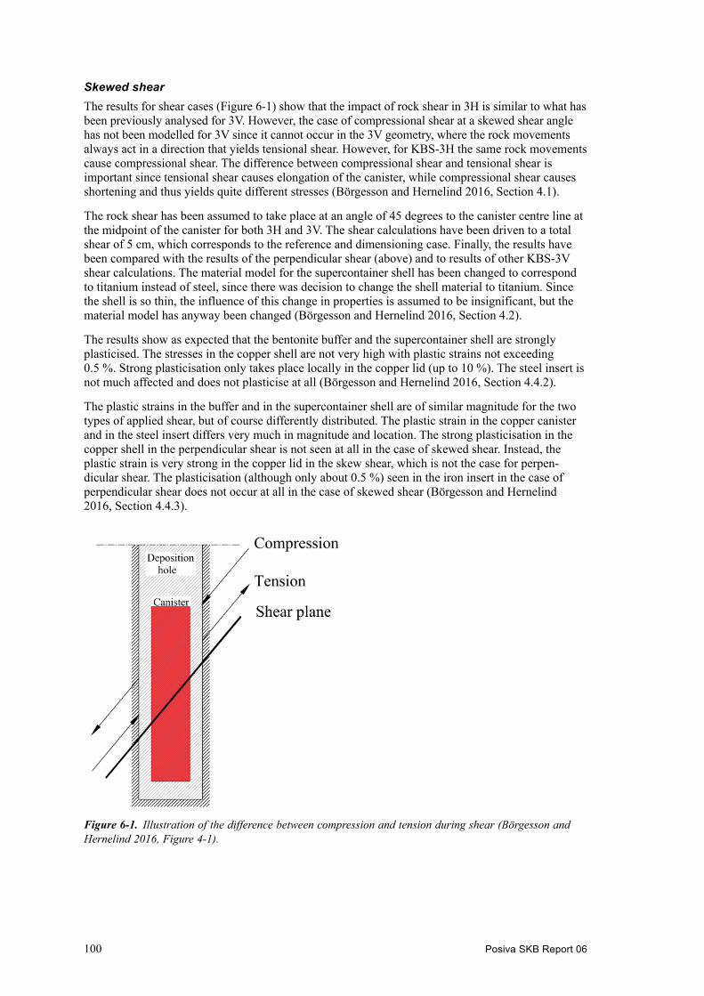
100 Posiva SKB Report 06
Skewed shearThe results for shear cases (Figure 6-1) show that the impact of rock shear in 3H is similar to what has been previously analysed for 3V. However, the case of compressional shear at a skewed shear angle has not been modelled for 3V since it cannot occur in the 3V geometry, where the rock movements always act in a direction that yields tensional shear. However, for KBS-3H the same rock movements cause compressional shear. The difference between compressional shear and tensional shear is important since tensional shear causes elongation of the canister, while compressional shear causes shortening and thus yields quite different stresses (Börgesson and Hernelind 2016, Section 4.1).
The rock shear has been assumed to take place at an angle of 45 degrees to the canister centre line at the midpoint of the canister for both 3H and 3V. The shear calculations have been driven to a total shear of 5 cm, which corresponds to the reference and dimensioning case. Finally, the results have been compared with the results of the perpendicular shear (above) and to results of other KBS-3V shear calculations. The material model for the supercontainer shell has been changed to correspond to titanium instead of steel, since there was decision to change the shell material to titanium. Since the shell is so thin, the influence of this change in properties is assumed to be insignificant, but the material model has anyway been changed (Börgesson and Hernelind 2016, Section 4.2).
The results show as expected that the bentonite buffer and the supercontainer shell are strongly plasticised. The stresses in the copper shell are not very high with plastic strains not exceeding 0.5 %. Strong plasticisation only takes place locally in the copper lid (up to 10 %). The steel insert is not much affected and does not plasticise at all (Börgesson and Hernelind 2016, Section 4.4.2).
The plastic strains in the buffer and in the supercontainer shell are of similar magnitude for the two types of applied shear, but of course differently distributed. The plastic strain in the copper canister and in the steel insert differs very much in magnitude and location. The strong plasticisation in the copper shell in the perpendicular shear is not seen at all in the case of skewed shear. Instead, the plastic strain is very strong in the copper lid in the skew shear, which is not the case for perpen-dicular shear. The plasticisation (although only about 0.5 %) seen in the iron insert in the case of perpendicular shear does not occur at all in the case of skewed shear (Börgesson and Hernelind 2016, Section 4.4.3).
Figure 6‑1. Illustration of the difference between compression and tension during shear (Börgesson and Hernelind 2016, Figure 4-1).

Posiva SKB Report 06 101
Differences with respect to KBS-3VSome of the shear cases modelled for KBS-3V (Hernelind 2010) that exhibit the highest plastic strains are compared with the results of the two KBS-3H shear cases (Table 6-1 and Table 6-2). Six different KBS-3V calculations are referred to. “Quarter” included in the name means that the shear takes place through the ¼ point and “half” or “mid” included in the name means that the shear takes place through the centre of the canister. “22” stands for a shear angle of 22 degrees relative to the canister axis and tension means tensional shear. “hori” stands for horizontal shear of a vertical fracture through the canister axis (“mid”) and through the plane that intersects the canister half way between the canister axis and the canister surface. The numbers 1‒9 in the tables corresponds to the location of the stresses and the locations are shown as colours in Figure 6-2 (see Hernelind 2010, Börgesson and Hernelind 2016, Section 5). The peak values for plastic strain occur at a few “hot spots” and therefore the results for the copper shell are reported for nine regions (in the cylindrical part, in areas containing the welds (top and bottom), in areas containing geometric discontinuity (top and bottom), the fillet regions (top and bottom) and finally the remaining regions (top and bottom), see Figure 6-2.
The results are given in Table 6-1 and Table 6-2. In order to allow comparison, the results after 5 cm shear in the perpendicular shear case have been used (Börgesson and Hernelind 2016, Section 5).
Table 6-1. Summary of results of plastic strain in the copper from different KBS-3V calculations and the two KBS-3H calculations shown at the two bottom rows (Börgesson and Hernelind 2016, Table 5-1). The highest values are shown in red. The region numbers are explained in Figure 6-2. PEEQ = equivalent plastic strain, CEEQ = effective creep strain.
Model name Model6g_xx
Plastic strain PEEQ/CEEQ [%] after 5 cm shearing
Copper shell region 1 2 3 4 5 6 7 8 9
normal_quarter_2050ca3 1.0 3.6 2.7 1.5 16 0.4 0.05 2.6 0.8normal_half_2050ca3 1.9 4.5 3.3 6.3 21 4.7 1.4 3.0 1.722_quarter_tension_2050ca3 1.5 14 9.5 2.4 15 9.3 0.9 5.5 1.222_mid_tension_2050ca3 0.7 4.3 5.1 1.8 15 0.9 1.0 0.9 1.2full_hori_quarter_2050ca3 0.7 4.2 5.0 1.1 4.3 2.7 1.4 1.6 1.3full_hori_mid_2050ca3 0.9 4.1 3.5 1.1 6.9 3.6 1.3 1.7 1.7kbs_3h (perpendicular) 0.96 4.6 3.5 3.1 16 0.4 0.15 0.96 4.6kbs_3h_skew 0.96 11.5 17.1 6.6 4.2 5.7 1.9
Figure 6‑2. Output regions for copper shell. Region 1 – mid canister (green). Region 2 – top weld (red, lower right). Region 3 – bottom weld (red, lower left). Region 4 – top discontinuous geometry (blue, lower right). Region 5 – bottom discontinuous geometry (blue, lower left). Region 6 – top fillet (yellow, lower right). Region 7 – bottom fillet (yellow, lower left). Region 8 – top reminding (grey, lower right). Region 9 – bottom reminding (grey, lower left). From Hernelind (2010, Figure 9-1).

102 Posiva SKB Report 06
Table 6-2. Summary of Mises’ stress in the copper from different KBS-3V calculations and the two KBS-3H calculations (Börgesson and Hernelind 2016, Table 5-2). The highest values are shown in red. The region numbers are explained in Figure 6-2.
Model name Model6g_xx
von Mises stress [MPa] after 5 cm shearing
Copper shell region 1 2 3 4 5 6 7 8 9
normal_quarter_2050ca3 103 145 147 121 201 81 85 109 103normal_half_2050ca3 139 99 149 134 254 130 94 112 9522_quarter_tension_2050ca3 128 268 185 112 133 174 96 179 9322_mid_tension_2050ca3 92 178 144 128 118 112 94 115 91full_hori_quarter_2050ca3 128 146 146 116 145 108 101 129 94full_hori_mid_2050ca3 107 98 142 121 171 118 99 115 98kbs_3h (perpendicular) 101 129 142 123 201 100 107 101 129kbs_3h_skew 96 157 204 149 104 149 102
The tables show that the highest Mises’ stress and the largest plastic strain is 204 MPa and 17.1 %, respectively, in the weld of the copper lid in the KBS-3H skewed shear case, while it is 254 MPa and 21 %, respectively, in the copper lid both in KBS-3V and KBS-3H in case of perpendicular shear through the centre of the canister. The results thus show that a rock shear in KBS-3H does not yield higher stresses and plastic strain in the copper canister than a rock shear in KBS-3V, despite the fact that the stresses are higher in the welds in case of KBS-3H than in KBS-3V (Börgesson and Hernelind 2016, Section 5).
UncertaintiesThere are uncertainties in the material models of the buffer and the canister materials as well as due to the limited resolution of the finite element mesh of the canister. However, these uncertainties are common to those identified for the corresponding KBS-3V analyses (Hernelind 2010) and are treated in that report (Börgesson and Hernelind 2016, Section 6.2).
The material models of the supercontainer shell do not include breakage of the steel or titanium, and the very large plastic strains (> 20 %) imply that the supercontainer shell would break at least when exposed to perpendicular shear. However, the effect of this is considered negligible since the super-container shell is strongly deformed and follows the contours of the rock and thus acts as it was broken (Börgesson and Hernelind 2016, Section 6.2).
The bentonite buffer is modelled with equal density inside and outside the supercontainer shell and no consideration has been taken to the deformation of the supercontainer shell during the water saturation and swelling process. In reality it is probable that the density will be lower outside the supercontainer and that the distance between the supercontainer and the rock surface will be reduced. However, this is judged not to affect the results significantly since the difference between modelled geometry and the expected real geometry is smaller than the difference between the model of KBS-3H and the model of KBS-3V and this difference had no influence on the stresses in the canister (Börgesson and Hernelind 2016, Section 6.2).
The supercontainer shell is modelled as a cylinder without the 10 cm diameter perforation holes. However, since properties that should yield the same average behaviour have been applied and since the effect of the supercontainer shell is anyway small, the conclusion is that this simplification is of no consequence (Börgesson and Hernelind 2016, Section 6.2).
ConclusionsThe conclusions of the performed modelling of one of the most severe cases of rock shear (perpen-dicular shear case) through KBS-3H are that the difference in consequences of the rock shear between KBS-3H and KBS-3V repository design variants is insignificant at the same type of shear. It is also concluded that the consequences of the uncertainties regarding the differences between the two models (for 3V and 3H) are insignificant. This means that the results and conclusions of the extensive investi-gations and modelling exercises of a rock shear in KBS-3V can also be used for KBS-3H (Börgesson and Hernelind 2016, Section 6.3).

Posiva SKB Report 06 103
Regarding the second calculation that concerned skewed compressional shear, the stresses in the welds of the copper lid were higher than corresponding stresses in the welds in all the modelled cases for KBS-3V. This needs to be considered, if a full safety case for KBS-3H is produced, includ-ing an analysis of scenarios (Börgesson and Hernelind 2016, Section 6.3).
6.2 Mechanical stability of deposition drift6.2.1 GeneralThe stability of a deposition drift has been analysed by Suikkanen et al. (2016) under different stress conditions occurring during the repository lifespan. The influence of these changes in stress conditions is analysed during three different phases of the repository lifespan: the construction phase, the thermal phase and the glacial phase. The near-field models are represented by cubes with side-lengths of 125 m in the linear elastic analyses and the 3DEC models. Each model contains five deposition drifts, of which only the middle drift is explicitly represented (Suikkanen et al. 2016, Section 5.2.3). The work is an update and extension of Lönnqvist and Hökmark (2007) using the latest site data from Olkiluoto (Posiva 2012e) and a site-specific repository layout (Posiva 2016c, Appendix 1), also accounting for the different types of spent nuclear fuel produced by the Finnish nuclear power plants (Ikonen and Raiko 2012) to be disposed of. The three different phases of the repository lifespan considered are (see also Hökmark et al. (2010) for a more detailed summary of the phases and the duration of each phase):
• The construction phase during which the rock transitions from an initial undisturbed state to the state after excavation of the deposition drifts with stress redistribution effects around the open-ings and reduced groundwater pressures.
• The thermal phase during which the heat generated by the deposited canisters will increase the temperature of the bedrock and induce thermal stresses, natural groundwater pressure will gradually be reinstated and the bentonite buffer will develop a swelling pressure (the time scales for the water uptake and ensuing swelling pressure build-up will vary considerably between supercontainer positions, depending on time of deposition, closure and local variations in bedrock hydraulic conditions).
• The glacial phase during which the state of stress will change as a result of the cyclic loading and unloading caused by a future ice sheet advance and retreat over the site. In addition to the changes in stress, there will also be dramatic changes in groundwater pressure (Suikkanen et al. 2016, Section 1.1).
In particular, the following issues that may influence potential migration paths for radionuclides have been studied (see also Figure 6-3 for a summary):
1. The stress magnitudes in the walls of the deposition drifts to identify regions of potential failure (i.e., failure due to increased tangential stresses in the floor and roof of the drifts or opening/initiation of radial (sub-horizontal) fractures in the walls of the drifts due to reduced tangential stresses).
2. The influence of a fracture network on the state of stress around the drifts.
3. The extent of failure and properties, such as the aperture of the rock damage zone surrounding the drifts on canister midpoint positions (Suikkanen et al. 2016, Section 1.2).
The first two issues described above have been addressed by use of three-dimensional distinct ele-ment models of the rock mass surrounding individual deposition drifts. In addition to these models, a large-scale model of the entire KBS-3H repository is analysed in order to obtain boundary conditions for the near-field models. The third issue is addressed by two-dimensional fracture mechanics models (Suikkanen et al. 2016, Section 1.2). These issues are addressed using the three-dimensional distinct element code 3DEC, v. 5.00 (Itasca 2013) and the two-dimensional boundary element code Fracod2D (Suikkanen et al. 2016, Section 1.3).

104 Posiva SKB Report 06
6.2.2 Results and conclusionsFrom the repository-scale modelling of the thermal phase, it is found that in some parts of the repository there is a possibility that the rock could be pre-heated and pre-stressed at the time of con-struction or deposition because of the heat generated by canisters deposited in nearest neighbouring drift several years previously (Suikkanen et al. 2016).
From the modelling of the drift construction, it is found that damage can occur in spatial locations of geological weaknesses, or at positions with localised high magnitudes of unfavourably oriented in situ stress components. The rock damage zone will extend due to thermally induced stresses during the thermal phase, when the tangential stresses at the floor and roof increase by 70–75 MPa. The detailed fracture mechanics models show that the swelling pressure of bentonite has a major impact on the extent of damage occurring during the thermal phase and during the subsequent glacial phase; the extent and width of the rock damage zone is reduced with the increase in swelling pressure (Suikkanen et al. 2016, Section 6.4.2).
The modelling of the glacial period by linear elastic models shows that the tangential stresses on the roof and floor of the deposition drift are lower during the glacial period than during the thermal phase. During the glacial phase at Olkiluoto, the stability of intersecting fractures is reduced, thereby increasing the aperture of rock damage zone due to the increase in pore pressure during the glacial phase (Suikkanen et al. 2016).
The main conclusion is that damage can be expected during all phases of the KBS-3H drift lifespan: the construction, thermal and glacial phases. The rock damage is concentrated on the roof and floor of the drift, where tangential stresses are highest. During the construction phase, minor damage can be expected in fracture locations. However, the rock damage zone on the floor and roof of the deposition drift is most profound after 30–50 years from the start of disposal of the spent nuclear fuel. The damage, when forming, tends to be fracturing orientated in a tangential direction of the drift perimeter (Suikkanen et al. 2016).
The fracture network (3DEC models with a fracture network, see Chapter 5 of Suikkanen et al. 2016) has generally a limited influence on the stresses in the rock surrounding the drifts during the construction phase and during the subsequent thermal phase compared with linear elastic models. The impact of the fracture network during the glacial phase is maximised due to the assumed high pore pressure levels (Suikkanen et al. 2016, Sections 7.3 and 8.1).
Regardless of the relevance of the assumed failure criterion, results from the linear elastic approach are relevant for providing boundary conditions for smaller and more detailed models (e.g., large scale 3DEC models to near-field 3DEC models or linear elastic 3DEC near-field models to 2D fracture mechanics models). The results from the 2D and 3D analyses are thus in qualitative agree-ment in terms of locations of potential rock failure (i.e., floor and roof) and also of the extent of potential failure (Suikkanen et al. 2016, Section 8.2).
Figure 6‑3. Issues addressed in the drift stability study, redrawn and modified after Lönnqvist and Hökmark (2007) (Suikkanen et al. 2016, Figure 1-2).

Posiva SKB Report 06 105
6.3 Effect of FPI criteria on utilisation6.3.1 GeneralAs part of the KBS-3H safety evaluation for Olkiluoto, an assessment of the risk for canister failure by shear movements has been carried out by Pekkarinen (2014). The aim was to assess the number of canisters that are intersected by large fractures, which have potential to undergo shear displacements large enough to break the canister, i.e. fractures with a diameter larger than 150 m (Fälth and Hökmark 2011). Three alternative FPC2 criteria to avoid intersections of canisters with such fractures were tested:
• Discarding canister positions coinciding with a full perimeter intersection (FPI) fracture (this criterion is given the code FPC1).
• Discarding canister positions intersected by an FPI fracture that is observed either a) in three adjacent KBS-3H drifts (FPC2A) or b) in six adjacent KBS-3H drifts (FPC2B). Canister positions are in both cases also discarded if the FPI is observed in a single boundary drift (so that it could be an FPI in the required number of drifts if the repository was larger).
• Applying no FPI criterion (FPCf) (Pekkarinen 2014, Sections 1, 4.2.5, 4.2.6, 4.2.7), implying that large fractures are not avoided when positioning the canisters, or rather supercontainers.
The analysis is based on a Monte Carlo simulation, where 1 000 realisations of the statistically modelled fractures are generated. For each realisation, the degree of utilisation and other metrics are computed, considering different FPC criteria and canister placement algorithms and rationale. The results were computed both with and without the deterministically modelled site scale fault zones; in this context only the fault zones with a maximum diameter of at least 1 000 m were considered (Pekkarinen 2014, Sections 1 and 3.5). The degree of utilisation is determined by the number of suitable supercontainer positions relative to the theoretical maximum, and describing whether the volume of rock can be utilised economically and effectively.
The work also included a similar analysis for the KBS-3V design, and a comparison of the degree of utilisation between the two disposal variants (Pekkarinen 2014, Section 1).
As a third, weakly related part of the work, was the evaluation of the suitability ratio (the fraction of the total drift length that can be used for canister emplacement) in the ONKALO demonstration area. The suitability was evaluated for the different FPC criteria, using fault zones from the detailed scale deterministic model and generating superimposed smaller fractures from the discrete fracture network (DFN) model (Pekkarinen 2014, Sections 1 and 6.4).
6.3.2 Results and conclusionsThe results for the degree of utilisation in the KBS-3H repository, based on the simulations, are sum-marised in Table 6-3.
Table 6-3. Summary of degree of utilisation values (%) for KBS-3H (Pekkarinen 2014, Table 4). DFN = Discrete Fracture Network model (statistical model defining e.g. the fracture size and orienta-tion distributions); BFZs = Brittle Fault Zones (modelled as closed 3D bodies); Opt. = optimised canister placement; Stat. = Placement according to a constant canister inter-distance (see text).
Model 1 (DFN only) Model 2 (also BFZs)
FPC1 FPC2A FPC2B FPC1 FPC2A FPC2B
Opt. Stat. Opt. Stat. Opt. Stat. Opt. Stat. Opt. Stat. Opt. Stat.
Mean 71.1 48.8 90.5 82.6 94.8 90.7 70.1 47.6 89.2 80.5 93.3 88.4Median 71.1 48.8 90.5 82.6 94.8 90.8 70.1 47.6 89.2 80.5 93.3 88.5Min. 68.7 46.2 88.5 80.0 93.3 88.3 67.8 44.9 87.4 78.0 92.0 86.0Max. 73.0 51.3 92.0 85.5 95.9 92.6 72.0 50.0 90.7 83.4 94.4 90.3Std.Dev. 0.62 0.84 0.51 0.89 0.43 0.74 0.62 0.83 0.50 0.87 0.40 0.72
2 FPC = Full Perimeter Criterion. 1. The condition that a fracture is an FPI (Full Perimeter Intersection) in a drift/tunnel. 2. A more detailed condition for considering an FPI in canister placement (Pekkarinen 2014, Section 2).

106 Posiva SKB Report 06
In all cases, the static canister placement3 gives significantly smaller degree of utilisation values than the optimal algorithm. The utilisation is also much poorer with FPC1 (around 70 % with optimal placement) than with the other FPC criteria (90−95 % with optimal placement), since many canister positions are discarded due to fractures that are, in reality, small. There is not much deviation in the values between simulation runs.
The mean number of rejected canister positions (NR) is 1 500−2 700 for FPC1, 500−1 000 for FPC2A and 270−600 for FPC2B. The lower values refer to optimal canister placement and the higher values to static placement (Pekkarinen 2014, Section 6.1.3). If no FPI criterion is applied (the case FPCϕ), the number of rejected canister positions would be 96 (optimal placement) or 133 (static) when the BFZs are avoided, and zero when they are not considered (Pekkarinen 2014, Section 6.18).
The proportion (mean percentage) of disposed canisters that intersect a large fracture (NL), undetected by the respective FPC criterion, is 0.4−2 % for FPC1, 1.7−3.4 % for FPC2A and 5.3−6.2 for FPC2B. The undetected large fractures in FPC1 are those that do not intersect the whole perimeter of a drift. In FPC2A and FPC2B also some large FPI fractures are ignored, if they intersect a drift at a sharp angle or near the drift end, so that the respective FPC criterion is not met (Pekkarinen 2014, Section 6.1.4 and Table 9). If no FPI criterion is applied (the case FPCϕ), the proportion of disposed canisters that intersect a large fracture would be approximately 6−12 % depending on the model and the placement algorithm (Pekkarinen 2014, Table 15).
According to the results, the criterion FPC1 seems too conservative. Most of the rejected canister positions are rejected in vain, since only a small fraction of the FPIs is caused by large (diameter larger than 150 m) fractures. The criteria FPC2A and FPC2B are better, although the degree of utilisation is still poor in the bounding drifts. The criteria also miss many large fractures. This could be improved by introducing a new criterion that takes the angle between the fracture plane and the drift into account (Pekkarinen 2014, Section 7).
In the KBS-3V design, the FPC criteria reject a much smaller number of canister positions than in 3H, since the tunnels have a larger cross-section than the drifts and this greatly reduces the number of FPIs. On the other hand, a larger number of canisters are placed in a critical position in the KBS-3V design, because the FPC cannot detect the large fractures that lie below the tunnels at the depth interval where canisters are located, unless they also intersect the tunnel (Pekkarinen 2014, Section 7).
6.4 Thermal analysis6.4.1 GeneralThe thermal evolution in the Olkiluoto KBS-3H repository has been analysed with the assumption that the conditions in the sealed deposition drift are initially dry and later becoming saturated. The maximum temperature at the interface between the canister surface and the buffer is reached in about 15 years after the disposal of the canister with its neighbouring canisters. The upper limit of the design temperature of the bentonite buffer is +100 °C. Given the initial dry conditions, in the dimensioning calculation, the maximum temperature is set to +95 °C. The 5 °C margin is demonstrated to be suf-ficient to cover for the variations of thermal properties of the materials in the designed structures and of the host rock. At water saturated conditions, the thermal conductivity of bentonite is much higher than at dry conditions and the maximum temperature is about +75 °C. However, because of the variation in the distribution of groundwater inflows to a single drift and specifically to a single supercontainer section, the potential for only limited saturation, or essentially “dry” conditions, during the first couple of tens of years after emplacement cannot be ruled out. The limiting temperature analysis is made using the initial (assembly) conditions in the drift. The compacted bentonite buffer is specified to have an initial water content of 11 or 17 % depending on block type, see Section 3.2. The analyses of KBS-3H repository temperature evolution are reported in Ikonen and Raiko (2015), where similar assumptions and modelling as for the analysis as for the KBS-3V repository (Ikonen and Raiko 2012) have been employed.
3 Static canister placement means that the canister positions are fixed, with constant spacings. When a canister position is inside an unsuitable segment (related to an FPI), the position is simply left empty. The optimal canister placement algorithm maximises the number of canisters by placing each canister at the first feasible position (Pekkarinen 2014, Section 4.3).
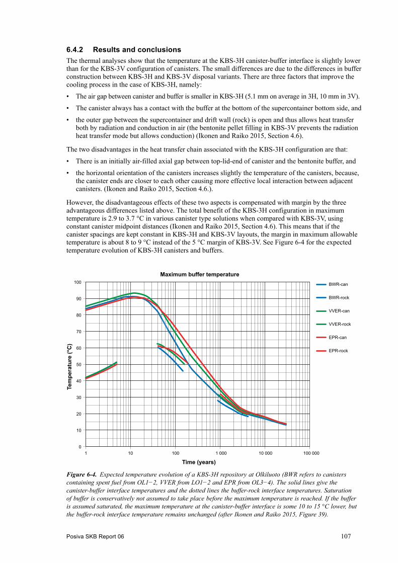
Posiva SKB Report 06 107
6.4.2 Results and conclusionsThe thermal analyses show that the temperature at the KBS-3H canister-buffer interface is slightly lower than for the KBS-3V configuration of canisters. The small differences are due to the differences in buffer construction between KBS-3H and KBS-3V disposal variants. There are three factors that improve the cooling process in the case of KBS-3H, namely:
• The air gap between canister and buffer is smaller in KBS-3H (5.1 mm on average in 3H, 10 mm in 3V).
• The canister always has a contact with the buffer at the bottom of the supercontainer bottom side, and
• the outer gap between the supercontainer and drift wall (rock) is open and thus allows heat transfer both by radiation and conduction in air (the bentonite pellet filling in KBS-3V prevents the radiation heat transfer mode but allows conduction) (Ikonen and Raiko 2015, Section 4.6).
The two disadvantages in the heat transfer chain associated with the KBS-3H configuration are that:
• There is an initially air-filled axial gap between top-lid-end of canister and the bentonite buffer, and
• the horizontal orientation of the canisters increases slightly the temperature of the canisters, because, the canister ends are closer to each other causing more effective local interaction between adjacent canisters. (Ikonen and Raiko 2015, Section 4.6.).
However, the disadvantageous effects of these two aspects is compensated with margin by the three advantageous differences listed above. The total benefit of the KBS-3H configuration in maximum temperature is 2.9 to 3.7 °C in various canister type solutions when compared with KBS-3V, using constant canister midpoint distances (Ikonen and Raiko 2015, Section 4.6). This means that if the canister spacings are kept constant in KBS-3H and KBS-3V layouts, the margin in maximum allowable temperature is about 8 to 9 °C instead of the 5 °C margin of KBS-3V. See Figure 6-4 for the expected temperature evolution of KBS-3H canisters and buffers.
0
10
20
30
40
50
60
70
80
90
100
1 10 100 1 000 10 000 100 000
Time (years)
Maximum buffer temperatureBWR-can
BWR-rock
VVER-can
VVER-rock
EPR-can
EPR-rock
Tem
pera
ture
(°C
)
Figure 6‑4. Expected temperature evolution of a KBS-3H repository at Olkiluoto (BWR refers to canisters containing spent fuel from OL1−2, VVER from LO1−2 and EPR from OL3−4). The solid lines give the canister-buffer interface temperatures and the dotted lines the buffer-rock interface temperatures. Saturation of buffer is conservatively not assumed to take place before the maximum temperature is reached. If the buffer is assumed saturated, the maximum temperature at the canister-buffer interface is some 10 to 15 °C lower, but the buffer-rock interface temperature remains unchanged (after Ikonen and Raiko 2015, Figure 39).

108 Posiva SKB Report 06
6.5 Hydrogeological and hydrogeochemical modelling6.5.1 GeneralAn essential part of the assessment of long-term safety of a repository is the analysis of groundwater flow, since (together with gas flow) it is the only means of transport of radionuclides to the biosphere, besides human intrusion. Hoek et al. (2016a) performed a groundwater flow modelling study for a KBS-3H repository at Olkiluoto to provide some of the necessary inputs required by Performance Assessment (Section 7.4). Underlying this study was the understanding of the site developed during the site investigations as summarised in the site descriptive model (Posiva 2012e), and in particular the description of Olkiluoto Hydrogeological DFN (discrete fracture network) model (Hartley et al. 2013). The main focus of the study was the next 50 000 years, which was assumed to be governed by temperate climate conditions, but the hydrogeological situation under glacial climate conditions was also evaluated by Hoek et al. (2016a).
A more comprehensive study of the evolution of hydrogeochemistry at Olkiluoto was carried out by Hoek et al. (2016b), aiming to understanding and quantifying the far-field reactive processes potentially relevant to the Olkiluoto site and to use these processes in a full three-dimensional simu-lation of the hydrogeochemical evolution in the region around the KBS-3H repository and to explore compliance with the defined performance targets. 3D reactive transport modelling of the geosphere has been applied to simulate the hydrogeochemical evolution at Olkiluoto. This has required an exploration of the appropriate processes and a verification of their numerical implementation. For that purpose, cross-verification between different codes (CrunchFlow and ConnectFlow) has been used and a sensitivity analysis performed with respect to the processes and mineral phases included (Hoek et al. 2016b).
6.5.2 Results and conclusionsThe primary outputs of the hydrogeological study by Hoek et al. (2016a) were repository performance measures relating to the distributions of groundwater flow around the deposition drifts, including flows through the rock damage (including EDZ and spalling). Other analyses considered the potential infiltration of dilute groundwaters to repository depth. A small set of sensitivity studies of these performance measures were performed by Hoek et al. (2016a) to quantify the robustness of results relative to uncertainties in the attributed characteristics of the drift, especially around the supercontainer locations.
Figure 6-5 shows the percentage of deposition drifts with inflows in various inflow ranges. It should be noted that most drifts have a length of approximately 300 m, but some are significantly shorter (Hoek et al. 2016a, Section 6.1.2).
The inflows under open conditions are used to determine possible supercontainer locations, based on maintaining a respect distance of 3−6 m to fractures with inflows greater than 0.1 L/min. The number of possible supercontainer locations satisfying these respect distances is 6 117. The utilisa-tion rate is summarised in Table 6-4 by waste type and overall. The utilisation rate is high (95 %) and consistent between the various parts of the repository (Hoek et al. 2016a, Sections 4.3.3 and 6.2). Other base case results can be found in Chapter 6 of Hoek et al. (2016a).
Table 6-4. Utilisation rate of the repository by waste type and overall, based on the inflow criterion. The theoretical maximum number of supercontainer locations is calculated by ignoring any inflows (Hoek et al. 2016a, Table 6-1).
Waste type Possible supercon-tainer locations
Maximum supercon-tainer locations
Utilisation rate
LO 1 & 2 2 330 2 437 95.6 %OL 1 & 2 779 811 96.0 %OL 3 3 008 3 174 94.8 %All 6 117 6 422 95.3 %

Posiva SKB Report 06 109
Three variants (no rock damage, continuous rock damage and rock damage with high conductivity) were studied to examine the sensitivity of near-field flows to the presence and properties of the rock damage around the deposition drifts. Flows in the fracture network around the deposition drifts were largely unchanged by the absence of a damage zone or higher transmissivity discontinuous damage zone, compared with the base case with rock damage concentrated around the supercontainer sections. The post-closure flows were slightly higher for the model case with continuous rock damage, and significantly higher for the case when the repository is under an ice margin that created an increased sub-vertical hydraulic gradient. The damage zone also acted to increase fracture network con-nectivity locally around the drifts, introducing some significant additional inflows during the open repository phase, but without a corresponding post-closure flow of any significance because of the limited circulation of flow from the natural water conducting system to these local fracture systems. If that were the case, the fracture (or cluster of fractures) was likely not connected to other ones (a dead-end fracture) and such a fracture would not carry much flow after repository closure (Hoek et al. 2016a, Chapter 9).
The post-closure hydrogeochemical modelling by Hoek et al. (2016b) used two different ways to check the fulfilment of the performance target for dilution (which could lead to chemical erosion of buffer material). Both gave consistent results indicating that 1 % (3D flow-paths combined with 1D analytical models) to 2 % (3D hydrogeochemical models; Table 6-5) of supercontainer locations in the proposed KBS-3H design variant could have groundwater diluted below a total charge equivalent target of 4 mM before the end of the temperate period, which is assumed to be 50 000 AD in this study (Hoek et al. 2016b). The 4 mM limit value is based on the potential for chemical erosion of buffer or filling components (see Table 2-2).
0.4 % 1.3 %
9.4 %
42.1 %
24.5 %
15.9 %
4.7 %
1.3 % 0.4 %0 %
5 %
10 %
15 %
20 %
25 %
30 %
35 %
40 %
45 %
50 %
-2.5 -2 -1.5 -1 -0.5 0 0.5 1 1.5
Perc
enta
ge o
f dep
ositi
on d
rifts
Inflow range [10log L/min]
Figure 6‑5. Distribution of log total inflows at open conditions into deposition drifts (233 in total) in inflow bins. The horizontal label is the lower end of the (0.5) interval (Hoek et al. 2016a, Figure 6-3).

110 Posiva SKB Report 06
Table 6-5. Numbers of supercontainer and filling block locations in the deposition drifts where the total charge equivalent of cations drops below the lower limit 4 mM in the variant with dilute infiltration (after Hoek et al. 2016b, Table 6-1).
Time Supercontainer locations (6 117)
Filling block locations (620)
Number below 4 mM
% Number below 4 mM
%
2000 AD 0 0.0 0 05000 AD 0 0.0 0 0
10 000 AD 0 0.0 0 020 000 AD 0 0.0 0 030 000 AD 10 0.2 9 1.540 000 AD 20 0.3 11 1.850 000 AD 113 1.8 39 6.3
The performance target set for chloride (which may lead to chloride corrosion of canisters) was not breached in any of the modelling cases by Hoek et al. (2016b). The performance target for sulphide (to avoid corrosion) could not be tested by Hoek et al. (2016b), since the formation of sulphide requires microbial activity, which was outside the scope of the study.
The inclusion of reactions alters the composition of the groundwaters without having a great impact on the performance indicators (TDS and total equivalent cation charge). The main effect is the exchange of calcium by sodium in the ratio of one to two. Since that is almost compensated by the mass ratio, the net effect on TDS and total equivalent cation charge is concluded to be small by Hoek et al. (2016b).
Some scoping calculations were also made by Hoek et al. (2016b) to study the impact of permafrost. The permafrost scenario used in this study starts at 50 000 AD (the presumed end of the temperate period) and lasts for 10 000 years. The assumptions are made that the shoreline and the location of lakes do not evolve during this period. The lakes are assumed to remain unfrozen at the bottom during the permafrost period (Hoek et al. 2016b, Section 3.4.6). Some clear indication of saline rebound was observed, reducing the number of supercontainer locations that suffer from dilute conditions beyond the end of the temperate period.
6.6 Chemical erosion and mass redistribution of bentoniteThe term “chemical erosion” refers to the loss of clay material under low ionic strength conditions. Recent safety assessments of a KBS-3V repository by Posiva and SKB (TURVA-2012 and SR-Site, respectively) have considered the possibility of loss of the buffer and backfill material taking place due to meteoric water infiltration during temperate climatic conditions or due to glacial meltwater intrusion, especially in association with glacial retreat, which is part of the glacial cycle. It was concluded in these assessments that significant buffer erosion is unlikely, but cannot currently be excluded in at least some of the 3V deposition holes (see e.g. Table 8-1 in Posiva 2012g). In the previous KBS-3H phase (Complementary Studies), it was recommended that, due to the potentially significant impact of chemical erosion on the design of a KBS-3H repository system, this process should be addressed in the next project phase (SKB 2012, Section 5.9).
6.6.1 Chemical erosion experiments on dipping fracturesIn order to simulate the potential erosion behaviour of bentonite buffer material that extrudes into fractures at a range of slope angles, a series of small-scale, flow-through, artificial fracture experi-ments has been performed (Schatz and Akhanoba 2016), as illustrated in Figure 6-6 (Smith et al. 2016, Section 4.1).

Posiva SKB Report 06 111
Experiments were conducted using custom-designed, small-scale, flow-through artificial fracture cells. Compacted samples were emplaced in the artificial fracture cell and the system was tightly sealed prior to the introduction of inflowing solute. Parameters that were varied include:
• Groundwater composition.
• Groundwater velocity.
• Fracture aperture and dip, and
• amounts of proxy accessory minerals (Smith et al. 2016, Section 4.1).
Test results for horizontally-orientated fractures are described in detail in Schatz et al. (2013) and tests on non-horizontal fractures are reported in detail in Schatz and Akhanoba (2016). In both cases, a clear distinction is observed between those tests for which erosive mass loss was observed and those for which it was not. Specifically, no sustained erosion was observed:
• For calcium exchanged montmorillonite (above about 90 % calcium on interlayer sites).
• For other purified montmorillonites if the total cation charge concentration in solution is sufficiently high (≥ 8.6 meq).
• For as-received bentonite materials if the total cation charge concentration in solution is ≥ 4.3 meq (Smith et al. 2016, Section 4.3).
The threshold cation charge concentration in solution for mass loss to take place was found to depend to some extent on the valency of the cations in solution (see below), but appears to be independent of other factors (fracture dip, groundwater velocity etc.) (Smith et al. 2016, Section 4.3).
6.6.2 Potential for dilute water infiltration during the present temperate periodThe total charge equivalent of cations provides an indicator that can be used to determine if condi-tions near a supercontainer location are sufficiently dilute so that chemical erosion could take place. Hydrogeochemical modelling has been carried out for a KBS-3H repository (see Section 6.5). The
Figure 6‑6. Top: set-up for the flow-through experiments and bottom: positioning of the test system at steep slope angles (θ ≥ 45°). From Smith et al. (2016, Figure 4-1).
112 Posiva SKB Report 06
chemical reactions considered were equilibrium reactions with the mineral phases calcite, pyrite and quartz including cation exchange in the rock matrix. It was observed that the resulting numbers of supercontainer sections and filling blocks in the drift experiencing dilute conditions (< 4 meq/L) are not very sensitive to the chemical reactions considered in the modelling, but that they are sensitive to the composition of the infiltrating water, as well as to the extent of the rock matrix considered in the evaluation of rock matrix diffusion (RMD). In all variants with infiltrating water reflecting the current composition of water (altered meteoric water) in the upper part of the bedrock observed at the site (the current total charge equivalent of cations is 7.4 meq/L), there are no supercontainer sections or filling blocks where the total charge equivalent of cations drops below the dilution limit of 4 meq/L. In the variant assuming dilute infiltration (total charge equivalent of cations of 0.4 meq/L) there are a number of supercontainer sections or filling blocks that start to have total charge equivalent of cations below the dilution limit of 4 meq/L after about 20 000 years (Smith et al. 2016, Posiva 2016d, Section 8.4.2).
Based on the current hydrogeochemical understanding of the site, it can be considered that the cur-rent altered meteoric water (7.4 meq/L) is representative for the entire temperate phase. At Olkiluoto, infiltration occurs mainly through the overburden, the thickness of which is likely to increase with time. In the overburden, reactions such as calcite dissolution and silicate weathering induced by respiration of organic matter and oxidation of detrital mineral sulphides increase the ionic strength of the infiltrating water. The total charge equivalent of cations could decrease in the event of significant climatic cooling, but this is not expected during the temperate phase (Smith et al. 2016, Posiva 2016d, Section 8.4.2).
Thus, the composition of water infiltrating the bedrock, altered by reactions in the overburden is likely to be such that the total charge equivalent of cations will remain above the assumed threshold value for chemical erosion of 4 meq/L throughout the present temperate climatic period. Also, the likelihood of dilute conditions arising at repository depth leading to chemical erosion of the buffer before next glacial period is very low. However, given the uncertainties in the composition of infiltrating water, an analysis has been conducted in which it is hypothetically assumed that the infiltrating water has not been altered by reactions in the overburden and has the total charge equivalent of cations below the threshold (Smith et al. 2016, Posiva 2016d, Section 8.4.2), see Section 6.6.3.
6.6.3 Approach to evaluate mass loss at dilute conditionsThe approach adopted in the present performance assessment (Posiva 2016d) to evaluate buffer mass loss as a function of time due to chemical erosion in a KBS-3H repository is summarised in Figure 6-7. It is assumed in this analysis that the total charge equivalent of cations of water infiltrat-ing the bedrock is below the threshold (< 4 meq/L) for chemical erosion. Although this is considered unlikely in reality, the possibility cannot currently be totally ruled out (Posiva 2016d, Section 8.4.3).
The first step is to evaluate the erosion rate in drift sections (supercontainer sections and sections with filling blocks) that would occur if dilute conditions were to prevail. This is done using simple geometric upscaling of the results from the above-mentioned small-scale, flow-through, artificial fracture experiments, with the fracture trace lengths and apertures taken from the discrete fracture network (DFN) model of the host rock4. It is assumed in this calculation that the filling blocks are made of the same material as the buffer. The consequences of erosion-resistant filling blocks also considered in Section 8.4.5 of Posiva (2016d).
The second step is to evaluate whether dilute conditions could in fact arise in at least some of the drift sections during the climate phase under consideration, and how long these conditions could prevail (Smith et al. 2016, Posiva 2016d, Section 8.4.3).
4 The main hydrogeological input for the current modelling study is the Hydro-DFN model reported in Hartley et al. (2013) derived from analysis of 53 long (KR) and 27 short (KRB) sub-vertical drillholes drilled from the surface along with 15 tunnel pilot holes (PH) drilled from the ONKALO tunnel.

Posiva SKB Report 06 113
The third step is to evaluate the amounts of mass loss that will occur in each drift section (super-container section or filling block) during the climate phase under consideration (i.e. the present temperate period). If, in a given drift section, dilute conditions are calculated in the second step to arise at a certain time, then the erosion rate is assumed to be zero before that time, and to take a fixed value at later times, until dilute conditions cease. The fixed value is that calculated for the drift section under consideration in the first step.
Chemical erosion during the temperate periodConsidering the present temperate period, the amount of mass loss clearly depends on how long it is assumed that the temperate period will persist before the onset of the next glacial period. The reference assumption for the present performance assessment is 50 000 years, although the impact of longer periods is also considered (Smith et al. 2016, Posiva 2016d, Section 8.4.3).
In the small-scale, flow-through, artificial fracture experiments, the mass loss rates per unit area of the sample/water interface under conditions where mass loss takes place are in the range of 500 to 1 250 kg/m2/a (upper bound rounded upwards to 1 500 kg/m2/a in the following assessment). For the supercontainer sections, the geometric scaling of these rates imply erosion rates of up to a few kilograms per year at some locations (Smith et al. 2016, Section 6.2.3). As expected, the highest erosion rates are for the filling blocks, since these will tend to be located where fractures with larger apertures intersect the drifts. The erosion rates for the filling blocks are, on average, around a factor of 3 higher than for the supercontainer sections.
If infiltration of the most dilute water (0.4 meq/L) is assumed, together with the reference rock matrix block size of 28.6 m, about 1 % of supercontainers will be exposed to dilute water during 50 000 years of temperate conditions. A similar result is obtained if the extent of the rock matrix block size is assumed to be infinite. For a reduced matrix block size of 5.4 m, about 15 % of the supercontainers encounter dilute water during the same period. Less sensitivity to the assumed total charge equivalent of cations of the infiltrating water is found if it is increased from 0.4 meq/L to 1 meq/L and to 2 meq/L (Smith et al. 2016, Section 6.3.2).
Figure 6‑7. Overview of approach to estimating buffer mass loss due to chemical erosion in a KBS-3H repository as a function of time (Smith et al. 2016, Figure 6-1).

114 Posiva SKB Report 06
Figure 6-8 shows, as a function of the duration of temperate conditions, the fraction of supercon-tainer sections that would experience erosion rates above various given values, assuming the upper bound erosion rate per unit wetted area of 1 500 kg/m2/a (possible variations in erosion rate with time are not considered). Two rock damage variants are compared: continuous rock damage along the drifts and no rock damage. The rock matrix diffusion depth (block size) is set to 28.6 m and the total charge equivalent of cations in the infiltrating water is 0.4 meq/L (Smith et al. 2016, Section 6.4.1).
After 50 000 years, which is the reference duration of the current temperate climate, around 0.5 % of positions experience erosion rates of 1 kg/a or more, irrespective of the representation of rock damage. This is clearly significantly less than the very long term figure of 40 % (also shown by Figure 6-8), indicating that a more prolonged temperate period would give rise to more positions experiencing such erosion rates. Only around 0.2 % of positions experience erosion rates of 3 kg/a or more after 50 000 years. Furthermore, even at longer times, the representation of rock damage is seen to have only a minor impact on the results (Smith et al. 2016, Section 6.4.1).
Chemical erosion due to glacial meltwaterGlacial meltwater penetrating the bedrock is likely to be very dilute, with a total charge equivalent of cations below 4 meq/L, and the methodological approach used in Section 6.6.3 for assessing buffer mass loss as a function of time due to chemical erosion on the assumption that dilute water infiltrates at the upper surface of the bedrock can thus be applied to periods of glacial retreat (Smith et al. 2016, Sections 6.3.2 and 9.1). The approch is explained in detail in Smith et al. (2016).
A key uncertainty is considered to be the initial total charge equivalent of cations in the rock matrix porewater during the ice-margin conditions. This was varied from its reference value of 200 meq/L to a much more pessimistic value of 25 meq/L. After 1 000 years of ice-margin conditions, and assuming 200 meq/L for the initial total charge equivalent of cations in the groundwater, only around 0.3 % of canister positions experience any chemical erosion at all. For the more pessimistic initial total charge equivalent of cations in the groundwater of 25 meq/L, around 4 % of supercontainer sections experience chemical erosion, with many of these positions having erosion rates of 1 kg/a or more (Smith et al. 2016, Posiva 2016d, Section 9.5.1).
Figure 6‑8. Fraction of supercontainer sections that would experience erosion rates above various given values as a function of the assumed duration of temperate conditions, assuming an erosion rate per unit fracture area of 1 500 kg/m2/a. Solid lines: continuous rock damage along the drifts. Dashed lines: no rock damage. Times beyond reference duration of the current temperate climate indicated with shading (Smith et al. 2016, Figure 6-9).
Posiva SKB Report 06 115
6.6.4 Buffer mass redistribution in response to chemical erosionThe number of supercontainer sections that could potentially experience advective conditions is determined not only by the rate of buffer mass loss to fractures, but also by the degree to which buffer mass redistributes itself within the drifts in response to mass loss. This is an issue that is also relevant to KBS-3V. However, it is a more significant concern for KBS-3H, because, if bentonite erosion at one location along the drift is sufficiently severe, it could potentially affect conditions not only around the nearest canister, but also around other canisters along the drift. This effect could in principle lead to erosion to one fracture causing successive canisters along the drift to become exposed to advective conditions and potentially fail due to corrosion (analogous to a row of falling domino tiles) (Posiva 2016d, Section 8.4.4). Thus, buffer mass distribution in response to erosion is discussed first, before an evaluation is made of the number of canister positions around which the buffer could potentially lose its safety functions.
Elastoplastic modelling has been used to study buffer mass redistribution in response to erosion. The present modelling work takes advantage of the UCLM-FS (FS = free swelling) model (Navarro et al. 2014), which has the capability of handling the high void ratios that may arise where the buffer is eroded (Smith et al. 2016, Section 7.2.1).
In a first application of the model, the presence of canisters and supercontainer shells along the drifts was disregarded. The results of the modelling of a bentonite-filled drift section show that erosion to fractures at rates of between 1 and 8 kg per year can give a region of low density near the location of erosion that extends some metres along the drifts after 1 000 years of erosion. The formation of a voids, which is also observed especially in cases with higher erosion rates and/or lower initial dry density, suggests that, in these cases, bentonite mass redistribution is too slow to supply material to the point of erosion at the assumed erosion rates, which in turn implies that the rate of erosion could then slow down. The degree to which the buffer homogenises following this period of erosion depends on the details of how erosion itself is conceptualised and is, in some cases, rather sensitive to the inclusion of friction between the buffer and the drift walls. In some calculation cases, the impact of wall friction is indicated to be such that subsequent buffer mass redistribution occurs initially, but then essentially ceases at most a few thousand years after the end of the period of erosion. However, because of various modelling uncertainties and simplifications, these findings are to be viewed as indicative, rather than as predictions.
In a second application, the impact of the presence of the canister and supercontainer shell on buffer mass redistribution in response to erosion was considered in detail. The results show that the radial stress (and dry density) inside the supercontainer shell varies little in the course of the simulations for all erosion rates considered; the confinement exerted by the shell was found to prevent the ben-tonite inside the shell from markedly changing its state, at least for the erosion rates and duration of erosion considered in the analyses. Furthermore, assuming an initially high dry density for the buffer both inside and outside the shell, a swelling pressure continues to be exerted on the drift wall outside the shell irrespective of the occurrence of erosion. However, if an initially low dry density is assumed (which may be the case if the bentonite inside and outside the shell has not fully homogenised by the onset of erosion), the confinement outside the supercontainer shell is reduced to the extent that contact between the bentonite and the host rock can be lost if the erosion rate is sufficiently high (in the order of 1 kg/a). Again, this implies that the rate of erosion could then slow down.
The UCLM modelling suggests that, while dilute water is present, the impact of erosion on buffer density will be limited to a few metres along the drift on either side of the fracture carrying dilute water, and that subsequent mass redistribution once erosion ceases could be rather limited because of friction. However, the parameter values used to model the effects of friction are highly uncertain and the possibility of more extensive buffer mass redistribution cannot currently be discounted. Thus, for estimating the consequences for the buffer (below), the following bounding assumptions are made: (i) ineffective buffer homogenisation, such hat the effects of erosion are confined to the supercontainer section or filling block where erosion takes place, and (ii), highly effective buffer homogenisation, such that the effects of erosion in one drift section propagate to neighbouring sections along the drifts (the “domino effect”). Two variants of the second case are also considered: (a) the filling blocks are assumed to be resistant to erosion and hence limit the propagation of the domino effect along the drifts and (b) the filling blocks are assumed to be composed of the same material as the buffer, and hence both are similarly affected by erosion.

116 Posiva SKB Report 06
6.6.5 Summary of consequences for the buffer in the temperate periods As noted earlier, the composition of water infiltrating the bedrock, altered by reactions in the over-burden is likely to be such that the total charge equivalent of cations will remain above the assumed threshold value for chemical erosion of 4 meq/L throughout the present temperate climatic period. Nonetheless, the consequences for the buffer have been evaluated assuming that the total charge equivalent of cations of water infiltrating the bedrock throughout the present temperate period is below the threshold for chemical erosion. The number of supercontainer sections and filling blocks that will experience advective conditions has been calculated for various combinations of assump-tions (see Smith et al. 2016 for details). Overall, the numbers of supercontainer sections and filling blocks calculated to experience advective conditions vary over a wide range according to the model assumptions made. As noted above, one such assumption is whether the effects of erosion are (i) confined to the supercontainer section or filling block where erosion takes place, or (ii) propagate to neighbouring sections along the drift. The first assumption gives smaller numbers of supercontainer sections and filling blocks with advective conditions than the second. Buffer homogenisation is, in this sense, a detrimental process, distributing the mass losses along the drifts and giving rise to the “domino effect”. The assumption of erosion-resistant filling blocks has little effect in the number of supercontainer sections with advective conditions, since the number of filling blocks per drift are rather small (typically just one or two) (Smith et al. 2016, Posiva 2016d, Section 8.4.5).
The least favourable set of assumptions combines the higher erosion rate inferred from upscaling of the laboratory experiment with a low matrix diffusion depth and a high degree of homogenisation of the buffer in response to mass loss. In this case, some 66 % of supercontainer sections experience advective conditions after a 50 000 year temperate period. By contrast, only 0.8 % of supercontainer sections experience advective conditions by this time if the lower erosion rate inferred from upscaling of laboratory experiment is assumed, combined with the higher matrix diffusion depth and assuming the effects of erosion are confined to the supercontainer section or filling block where erosion takes place (Smith et al. 2016, Posiva 2016d, Section 8.4.5).
The assumed duration of the temperate period is also a sensitive parameter. However, the assumed total cation concentration of meteoric water infiltrating at ground surface and the representation (or not) of the damaged zone have relatively little impact on the results for the cases considered, although clearly if the total cation concentration of the infiltrating meteoric water had been assumed to exceed 4 meq/L, i.e. the assumed threshold total cation charge concentration for mass loss to take place, then no erosion would occur (Smith et al. 2016, Posiva 2016d, Section 8.4.5).
There are a number of assumptions made in these calculations, many of which are conservative, as well as observations of natural and laboratory systems, that suggest chemical erosion may be far less than that suggested by the calculations. One key observation is that bentonite that is lost by erosion can become immobilised at fracture constrictions and by adhering to fracture walls and thus the use of a continuous constant erosion rate is a conservative approach. Insoluble detritus in the bentonite could also plausibly become lodged in constrictions within the fractures, favouring clogging of these fractures. It is shown that just a fraction of the bentonite calculated to be lost by erosion is sufficient to clog the fracture space in the rock below the repository if the eroded bentonite were to become immobilised. In this case, it is likely that further mass loss by erosion would either cease or be substantially reduced.
6.6.6 Complementary considerationsComplementary evaluations have been made to highlight the main uncertainties in the number of positions where advective conditions could occur in a KBS-3H repository before the next glacial period, and they indicate overall that these numbers may be over-estimated. The considerations are presented in full in Smith et al. (2016).
For example, there is no unambiguous hydrogeochemical evidence from the Olkiluoto site to indicate that dilute water has penetrated to repository depth during previous glacial cycles, although, because of the presumed long duration of the current temperate period due to anthropogenic effects, this does not necessarily imply that such penetration is impossible before the next glacial period. Nonetheless, there is reason to believe that the composition of water infiltrating the bedrock will be

Posiva SKB Report 06 117
such that the total charge equivalent of cations will remain above the assumed threshold value for chemical erosion of 4 meq/L throughout the present temperate climatic period and that the likelihood of dilute conditions arising at repository depth leading to chemical erosion of the buffer before the next glacial period is very low (Smith et al. 2016, Sections 9.1 and 9.2).
Other hydrogeochemical evidence from the Olkiluoto site indicates that dilute glacial meltwater or meteoric water has not penetrated to repository depth during previous glaciations. In particular, isotopic signatures of glacially derived waters are seen only above a depth of 300 m (Posiva 2012e, Smellie et al. 2014, Smith et al. 2016, Section 9.1).
6.6.7 Chemical erosion during long-term evolutionSimilarly to the present temperate period, there is reason to believe that the composition of water infiltrating the bedrock during the subsequent temperate periods will be such that the total charge equivalent of cations will remain above 4 meq/L (the assumed threshold value for chemical erosion) and that the likelihood of dilute conditions arising at repository depth leading to chemical erosion of the buffer is very low even during the long-term evolution of the repository. Furthermore, even assuming that water sufficiently dilute to support chemical erosion infiltrates the upper surface of the bedrock, the 1-D modelling with rock matrix diffusion (RMD) used in Section 6.6.3 suggests that future temperate climatic periods would have to be in the order of tens of thousands of years long for dilute conditions to reach any of the supercontainer sections. However, temperate climatic periods during future glacial cycles are likely to be significantly shorter than the present temperate period, assuming that there are no anthropogenic effects on climate at these distant times. It is therefore expected that glacial meltwater intrusion in association with glacial retreat, rather than meteoric water infiltration, is the most likely cause of chemical erosion during subsequent glacial cycles.
6.7 THM modelling6.7.1 GeneralThe KBS-3H spent nuclear fuel repository concept involves different types of complex behaviour. Coupled thermal, hydraulic and mechanical processes develop after excavation of the tunnels and drifts, emplacement of the supercontainers containing the spent fuel canisters, emplacement of the distance blocks between supercontainers, closing the drifts with the metal plugs, pellets filling, filling the gap between supercontainers and blocks with water and sealing of the repository (Pintado et al. 2016, Section 1.2).
The temporal evolution of temperature, saturation, liquid pressure, strains and stresses in the components of the engineered barrier system in the KBS-3H variant has been studied by Pintado et al. (2016) using numerical methods. A set of laboratory tests was used to calibrate the parameters employed in the models. Down-scaled tests were also used to quantify some of the special issues of this alternative, such as the presence of the supercontainer and the gap between the supercontainer and the rock. Results from an “in situ” test (the Multi-Purpose Test, MPT) were also used for the validation of the hydraulic parameters. The modelling consisted of thermo-hydraulic and thermo-hydro-mechanical analysis, in which the significant thermo-hydro-mechanical processes, parameters and features were incorporated. CODE_BRIGHT was used for the quantitative finite element modelling (Pintado et al. 2016).
The modelling of thermal, hydraulic and mechanical behaviours presents challenges of varying degrees of complexity. The thermal model is relatively simple. The models used to predict the hydraulic behaviour are more complex and non-linear (Pintado et al. 2016, Section 1.2).
The main objective of the THM modelling was to achieve an improved understanding of the thermo-hydraulic and thermo-hydro-mechanical processes, and material properties that affect the behaviour of the buffer materials after their installation in the repository, as well as to conduct a parametric study that will assist to accurately predicting the barriers’ behaviour, specifically for the period between the end of the operational phase to the target state, the latter which corresponds to full saturation of the buffer (Pintado et al. 2016, Section 1.1).

118 Posiva SKB Report 06
The work by Pintado et al. (2016) supports the task of defining the essential steps involved in designing a clay barrier that will safely and securely isolate the canisters containing spent fuel. Both boundary and initial conditions as well as the repository geometry must be established before modelling can proceed. The reference geometry selected is that of the Olkiluoto 1 and 2 canisters (Table 3-1). Thermal analyses for the entire repository were carried out using an analytical solution (Ikonen and Raiko 2015) and were then used to define the boundary conditions of the geometries analysed in Pintado et al. (2016, Section 1.1).
6.7.2 Results and conclusionsThe material parameters, constitutive models, and assumptions made were carefully selected for all the modelled cases (see below). The reference parameters selected for the simulations were evaluated using laboratory measurements. The modelling results highlight the importance of understanding groundwater flow through the fractured rock mass to achieve reliable predictions regarding buffer saturation, this while saturation times could range from a few years to one thousand years depending on the hydrogeological conditions in the rock. In addition to the rock hydraulic conductivity and fracture transmissivity, the saturation process was significantly affected by the material properties of the buffer. The effects of heat flow and vapour transport were less significant. With respect to the thermal evolution, the thermal conductivity of the repository components and the behaviour of air gaps in the buffer were the key variables (Pintado et al. 2016).
The models reported by Pintado et al. (2016) were aimed at analysing the hydro-mechanical evolu-tion and final saturated state in the transition zone. The models can be divided into two classes:
1) Models with radically different mechanical parameterisations (“Base case”, “Reference case”).
2) Models that explore the sensitivity of the modelling outcome of a single parameter (“ClayTech_TZ_1” and “ClayTech_TZ_2”, which both are based on the reference case).
The two different classes of models are discussed separately below (Pintado et al. 2016, Section 10.5).
Mechanical parameterisation of bentoniteGiven the nature of the bentonite it could be expected that after full saturation, the net-mean stress in the bentonite that has undergone swelling would be equal to the swelling-pressure curve at the dry density in question (the swelling pressure curve is a fit to the lower end of the swelling pressures measured in the laboratory for varying dry density, which is appropriate to use for those parts of the buffer that only undergo swelling). Points in the buffer that have undergone consolidation can, however, be expected to end up on a higher pressure at the same dry density − roughly twice that of the swelling pressure curve − due to the hysteretic behaviour of bentonite; see Chapter 7 in Åkesson et al. (2010b) for a discussion on this subject (Pintado et al. 2016, Section 10.5.1).
When comparing the three different mechanical parameterisations of bentonite used here (Base case, Reference case and B+Tech 29 case) only the reference case model shows this type of behaviour, whereas in the Base case and B+Tech 29 models the net-mean stress in the swelling parts of the buffer in general is too low, while the consolidating parts (the interface and pellet materials) show a much too high net-mean stress (Pintado et al. 2016, Section 10.5.1).
In the base case, this comes out as expected, as the low-density regions (pellets and interface zones) have been given identical mechanical parameters as the blocks (only the initial dry density and degree of saturation is different). With such a parameter choice and using the BBM (Barcelona Basic Model; Pintado et al. 2016, Section 4.3.5) description of the bentonite, it is not possible to accurately capture the mechanical evolution in the pellets filling/interface material in a KBS-3H repository (Pintado et al. 2016, Section 10.5.1).

Posiva SKB Report 06 119
In Figure 6-9, the dry density after the bentonite has been fully water saturated is shown for the Base case and Reference case together with the initial state (top plot). As can be seen, the results of the base case model show heterogeneity, while the reference case model result looks well homogenised. The low degree of homogenisation in the Base case and models is not realistic, as it indicates that the pellets and interface material are much stiffer than what experimental tests would suggest. In any case, it should be considered that the parameterisation of MX-80 in the Base case was done for the KBS-3V variant (Pintado et al. 2016, Section 10.5.1) and it is not appropriate for the KBS-3H variant.
Single-parameter sensitivity analysisThe two models (Claytech_TZ_1 & ClayTech_TZ_2) that explore the sensitivity of the results to a single parameter were used to: 1) check the effect of the strength of the wall friction; and 2) explore the importance of anisotropic swelling (Pintado et al. 2016, Section 10.5.2).
The importance of wall friction was explored by increasing the value of the friction angle from 5 to 10 degrees in model ClayTech_TZ_1. The final dry-density distribution and effective-stress profile in the reference case and ClayTech_TZ_1 is shown in Figure 6-10. As can be seen, the increased value of the friction angle leads to a shorter (along the drift axis direction) zone with lowered dry density (as compared to the density if only radial swelling is allowed). The decrease in length of the transition zone corresponds rather well to the decrease suggested by the analytical solution, even though the absolute values of the length of the transition zone is longer in the numerical models (Pintado et al. 2016, Section 10.5.2).
Increasing the value of the Poisson’s ratio in the buffer (as in ClayTech_TZ_2) was done to check the effect of a more isotropic swelling. This may perhaps be a more realistic model than the original reference case as the bentonite initially has a rather high water content. A comparison of the final state of the reference case and ClayTech_TZ_2 is shown in Figure 6-11 (Pintado et al. 2016, Section 10.5.2).
Figure 6‑9. Final dry density for each of the models using three different mechanical parameterisations (Base case, Reference case and B+Tech 29). As can be seen, only the reference case shows significant homogenisation (Pintado et al. 2016, Figure 10-14). The model dimensions are shown in the lowest figure.

120 Posiva SKB Report 06
The differences in the results between the two models are quite small. As can be expected, the effec-tive stress in the drift direction is slightly lower at the centre of the drift in the model with a higher Poisson’s ratio, as the swelling is somewhat more isotropic. This also has the effect of a slightly more radially homogenised solution (as can be seen in the left graph) leading to slightly higher stress values along the rock wall. In general, changing the value of Poisson’s ratio has a very small effect on the result in this modelling exercise. This is reassuring, although it should be noted that the Poisson’s ratio can vary, for instance with higher values with resulting increase of stress levels during compression (see e.g. Åkesson et al. 2010a, Pintado et al. 2016, Section 10.5.2).
Conclusions and uncertaintiesThe inner gap between canister and buffer ring blocks has a significant effect on the buffer tempera-ture and the results show that the gap will be closed before the maximum temperature expected in canisters is reached. Hence, it will give a certain margin of safety because all thermal calculations done for the design assumes that the inner gap is always open (Pintado et al. 2016, Section 12).
Figure 6‑10. Dry density (left) and effective stress (right) profiles in the reference case (black lines) and ClayTech_TZ_1 (orange lines) models. The solid lines with open circles identify the solution at the central axis of the drift while the solid lines with filled circles identify the solution on the rock wall. The dashed lines identify the analytical solution (Pintado et al. 2016, Figure 10-15).
Figure 6‑11. Dry density (left) and effective stress (right) profiles in the reference case (black lines) and ClayTech_TZ_2 (orange lines) models. The solid lines with open circles identify the solution at the central axis of the drift, while the solid lines with filled circles identify the solution on the rock wall. The dashed grey line identifies the analytical solution (Pintado et al. 2016, Figure 10-16).

Posiva SKB Report 06 121
Most models indicate that the saturation process will take place during the first ten years. Only extreme cases show longer saturation times but in all cases the saturation time is less than one thousand years. The unfractured rock representation used in the extreme cases is not realistic, so this type of solutions should be regarded as providing a bounding reference (Pintado et al. 2016, Section 12).
The models give swelling pressures above 2 MPa against the drift surface except in parts of the buffer close to the supercontainer lids (end plates) (Pintado et al. 2016, Section 12).
The model and parameters fit very well with results gathered from a mock-up and an “in situ” test in terms of hydraulic behaviour. The “Initial state” seems to be a good approximation for avoiding the modelling of the gap filling but it should be studied in greater detail, especially when data from mock-up tests and the MPT test are available (Pintado et al. 2016, Section 12).
A general uncertainty concerns the overall treatment of the hydro-mechanical behaviour. Measure-ments and tests of bentonite clay in general show that both its hydraulic and mechanical properties display a significant dry-density dependency. However, with the material models at hand in CODE_BRIGHT, such dependencies cannot be directly implemented. This is especially important concerning the hysteretic swelling/compression behaviour. Because of these limitations, the predictive capabilities of the models are limited (Pintado et al. 2016, Section 10.5.4), and the importance of comparing modelling results with experimental ones is thus highlighted.
6.8 Titanium-clay interaction6.8.1 GeneralThe knowledge on the reactivity of Ti with clay materials is of fundamental importance in the context of assessing the overall performance of the barrier systems. In particular, potentially adverse effects of titanium and its corrosion products need to be assessed in detail. It is important to constrain the chemi-cal nature of the species formed after the Ti corrosion products have reacted with clay barrier materials. Possible molecular interaction mechanisms of Ti with clays include: i) sorption by cation exchange, ii) specific (inner-sphere) sorption to clay edge sites, iii) substitution of Al and Si by Ti in octahedral or tetrahedral clay sites and iv) precipitation of secondary phases such as TiO2, Ti-Fe oxides or Ti silicate phases. Sorption processes and the formation of nano-crystalline or amorphous (‘gel-like’) Ti-oxide phases may influence the retention characteristics and the swelling properties of the clay barrier. Identifying the predominant molecular interaction processes is crucial in order to assess potential impacts on safety functions of the clay barrier (Wersin et al. 2016, Chapter 1).
The reactivity of titanium towards the bentonite clay has been the focus of an experimental programme included in the KBS-3H System Design Phase. Three studies have been carried out between 2013‒2015 and reported by Wersin et al. (2016).
6.8.2 Results and conclusionsIn the first study, the nature of Ti in natural clays was analysed by X-ray absorption spectroscopy. The results indicated that Ti in MX-80 bentonite is incorporated in the clay structure, whereas in the high Ti-containing Rokle bentonite, Ti occurs predominantly as separate TiO2 phase (anatase). There are no indications from XANES and EXAFS of structural Ti in the clay, thus this amount is at maximum ~5 % of the total Ti. The content and chemical environment of titanium in the bentonite appears to have no significant effect on the favourable bentonite properties, i.e. high swelling capacity and low hydraulic conductivity (Wersin et al. 2016, Section 5.1).
In the second study, synthetic montmorillonite (“Ti-free”) was exposed to Ti foil and Ti powder at 80 °C for periods up to 20 months. Spectroscopic analysis (XANES, EXAFS) revealed that Ti released by corrosion had reacted with the clay mineral and was incorporated in a newly formed phyllosilicate structure. No indications of the formation of a separate TiO2 phase were found. From micro-XRF analyses the amount of Ti transferred to the clay could be estimated. The derived average corrosion rates were found to be in the range of about 1−10 nm/a. The corrosion rate was lower for a clay sample exposed to coarse Ti powder than what was obtained for the samples exposed to foils. One reason for this difference may be that the foils were etched with acid prior to use, but the Ti powder was not (Wersin et al. 2016, Section 5.3).

122 Posiva SKB Report 06
In the third study, hydrothermal tests at 200 °C with synthetic montmorillonite and Ti foil and Ti powder were conducted. Microscopic and spectroscopic analysis indicated no changes of the clay mineral under neutral and acidic conditions, but some alteration under alkaline conditions. These alterations, however, occurred independently of the addition of Ti. The results are discussed in detail in Wersin et al. (2016, Section 3.3).
Based on the obtained results, the effect of Ti on the bentonite buffer is expected to be very limited.
6.9 Stray currents6.9.1 GeneralA pre-study on possible corrosion effects of electrical fields in a KBS-3H repository has been reported by Taxén (2016). A case where a 600 m long drift (equivalent to two 300 m drifts in a series) with supercontainers with titanium shells separated by bentonite distance blocks located in an electrical field has been studied. The path of the electrical current in the drift has been simulated using FEM-models and approximated using simple resistance models.
In the general vicinity of the Olkiluoto repository site, there is only one electrode for power transmission of High Voltage DC-currents (HVDC). The electrode is located in the sea but close to coast roughly south of the repository site. The electrode station for the Fenno-Skan HVDC cables is located about 35 km from the repository (Taxén 2016, Section 2.2).
Just as for the repository at Forsmark on the Swedish side, there is a nearby power plant. Forsmark power station was found to behave similar to a secondary electrode to the Fenno-Skan electrode at the Swedish coast. It is likely that the Olkiluoto power station will behave similarly to Forsmark power station. The origin of the secondary electrode effect is that the power plant is connected to remote ground via ground cables in over-head transmission lines. Thus, current from the HVDC electrode is picked up by the local ground grid at the power station and transmitted to remote ground via the transmission lines. The effect is that of current entering or exiting the ground at the power station, creating an electrical field that is superimposed on the electrical field from the HVDC electrode. This, in turn, results in potential gradients that are steeper close to the power plant than at longer distances from any power plant (Taxén 2016, Section 2.3).
6.9.2 Results and conclusionsFor the KBS-3H concept, an electrical circuit model for a representative part of a deposition drift has been derived, with the drift consisting of several equivalent circuits in series. Figure 6-12 shows the equivalent circuit with resistors that symbolise the current’s path through the deposition drift. Rb1 represents the resistance between the end of one copper canister and the beginning of the next. Thus, Rb1 includes the resistance in the distance block and the resistance inside the supercontainer between the solid end plate and the beginning of the copper canister. Rb1 is shown to be strongly influenced by the narrow annular gap/space between the solid end plate of the titanium supercontainer and the rock wall of the drift (Taxén 2016, Section 3.2).
Rb2 represents the resistance in the bentonite parallel to the copper canister and Rc represents the resistance for current entering and exiting the copper canister. The resistance circuit in Figure 6-12 is a simplification that aims at describing the currents for the expected conditions where Rc>>Rb2. For other cases, Figure 6-12 would be a poor approximation (Taxén 2016, Section 3.2).
The drift is assumed to have constant resistivity which is much lower than the surrounding rock. The averaged resistivity along the drift is calculated by Taxén (2016, Section 3.3). Potentials that are locally independent of the location along the drift indicate that there is no or only small currents in the drift. This is observed at both ends of the conceived 600 m drift, red curve in Figure 6-13 at −300 m and at 300 m. The drift gradually picks up current from the high resistivity rock. At either end of the drift the currents are small and the highest currents are found close to the centre of the drift (Taxén 2016, Section 3.3).

Posiva SKB Report 06 123
The change in current for each length of a supercontainer is small. It is the gradual changes over the lengths of many supercontainers that add up to a current that may be significant at the supercontain-ers located close to the centre of the drift pairs. It is not an unreasonable approximation to treat the boundary between rock and bentonite as insulating when one single supercontainer or one single representative length (½ of the supercontainer length + ½ of the distance block length) is considered (Taxén 2016, Section 3.3).
Applying the resulting field strength to a supercontainer and associated copper canister located close to the middle of a drift it was found that it would be subjected to a field strength of 0.036 V/m. Along the representative length of 5.075 m there would be a voltage difference of 0.183 V. The resistance model can then be used to calculate the potentials along the copper canister surface. Using a voltage of 0.183 V gave 0.083 V as the potential at the circular end surface of the copper canister (Taxén 2016, Section 3.4).
It was found that a small fraction of the current in the drift would pass through the copper canister, causing corrosion at the points where the current exits the canister. An example using 600 m long drifts (2x300 m) in 10 000 Ωm resistivity rock showed that a uniform electrical field of 50 V/km, in the direction of the drift, would result in an increased corrosion rate by about 0.06 µm/year for a copper canister located close to the middle of the drift (Taxén 2016, Chapter 5).
Since sulphide from the bentonite or groundwater is a prerequisite for the formation of copper sulphide and the sulphide concentrations are low, the formation of copper sulphides may be more controlled by local sulphide availability than by electrochemical potential (Taxén 2016, Section 4.4).
Figure 6‑13. Potentials at three locations in the model volume. The black curve shows the potentials in homogeneous rock, far from any drift or tunnel. The blue curve shows the potentials at locations 50 m above the centre drift. The red curve shows the potentials at the centre of the centre drift (Taxén 2016, Figure 3-11).
Figure 6‑12. Resistance circuit for the row of two supercontainers with distance blocks. The red lines indi-cate the limits of a repeated unit. This is called the smallest representative unit (Taxén 2016, Figure 3-3).


Posiva SKB Report 06 125
7 Long-term safety evaluation
7.1 IntroductionA long-term safety evaluation for KBS-3H is being carried out for Posiva’s Olkiluoto site. In this project phase, the following main safety evaluation reports have been produced:
• Design Basis (Posiva 2016a); see Chapter 2 of the present report.
• Description of the Disposal System (Posiva 2016j); see Section 7.2.
• Features, Events and Processes (Posiva 2016k); see Section 7.3.
• Performance Assessment (Posiva 2016d); see Section 7.4.
The focus of the work is on developing the knowledge on the long-term performance and impact on long-term safety of the KBS-3H design to a sufficient level of detail to provide an assessment of safety as presented in the regulatory criteria, and furthermore, provide reliable information for the comparison of the two design variants of the KBS-3 concept. The main differences between the two disposal variants are associated with the deposition drift and in the components that are emplaced in a deposition drift. Many of the safety-related issues are similar to KBS-3V and results from SR-Site (SKB 2011) and Posiva’s safety case TURVA-2012 (Posiva 2012b) for KBS-3V are considered also in the KBS-3H safety evaluation.
In addition to the recent KBS-3V safety cases/safety assessments for KBS-3V, the results from the first long-term safety assessment done for KBS-3H (Smith et al. 2007) have been used to the extent possible, while also taking into account the changes in design, layout, supercontainer material and other changes since 2007‒2008.
7.2 Description of the disposal system7.2.1 Aims and scopeThe initial state of the disposal system assumed in the KBS-3H safety evaluation 2016 is given in the Description of the Disposal System report (Posiva 2016j).
The disposal system is an entity composed of a repository system and surface environment. In the horizontal disposal variant KBS-3H, the repository system includes the spent nuclear fuel, canister, buffer, filling components, compartment plugs, drift plugs and closure components as well as the host rock and the related underground openings. The repository system components have safety functions (except for the spent nuclear fuel) and are subject to requirements. The KBS-3H deposition drift also includes some minor components − such as the supercontainer shell − that do not have safety functions.
The objectives of Posiva (2016j) are:
• To describe the KBS-3H disposal system in its initial state; this includes the repository system including the repository and other underground openings and host rock, and the surface environment, and
• to define the range of possibilities for the initial state for the spent nuclear fuel, EBS components, host rock and surface environment.
Conditions for each component vary in time and space, due to the time of emplacement and due to the tolerances set for the compositions, geometries and other properties depending on the component. Several of the components of the KBS-3H repository are similar to those in a KBS-3V repository, which is why Posiva (2016j) is partly based on an equivalent report produced for the TURVA-2012 safety case for KBS-3V in 2012 (Posiva 2012d).

126 Posiva SKB Report 06
7.2.2 Initial state of the engineered barriers and other drift componentsFor any engineered barrier or other drift component, the initial state is defined as the state it has when the direct control over that specific part of the system ceases and only limited information can be made available on the subsequent development of conditions in that part of the system or its near field. In KBS-3H, the initial state for all drift components in one drift compartment is when the artificial water filling has been performed, the water filling pipes and the air evacuation pipe have been removed, the ball valve of the lead-through tube has been closed and the operations in that particular drift compartment have, thereby, ceased (Posiva 2016j, Section 1.8). The initial state of the closure components is defined essentially by the time of emplacement of the closure components.
The initial state of any given EBS component is not expected to vary greatly between locations within the disposal facility and will not depend greatly on the time of emplacement, since the initial state is constrained by the requirements set on a given component. However, the heterogeneity of the surrounding host rock implies that the subsequent evolution of EBS components will vary. Due to the artificial water filling, the initial state of the EBS components in KBS-3H is probably more homogeneous and less dependent on the properties of the host rock than in the case of KBS-3V (Posiva 2016j, Section 1.8).
The initial state is presented for each component, and references to the main supporting reports are given to guide the reader for more details. The design of the KBS-3H components is presented in Chapter 3 and will not be repeated here. One design solution that was not specified in Chapter 3 is the titanium grade assumed to be used in the compartment and drift plugs. In the safety evaluation, Titanium Grade 12 was assumed.
It has been evaluated in the Production Line reports (see Chapter 4) that the design of the plugs and the supercontainer shell conforms to the reference design (Posiva 2016f, Section 7.1, Posiva 2016g, Section 7.1). As to buffer and filling components, the initial state includes a range of densities and other properties both for various buffer components and the buffer as a whole. However, based on calculations it can be stated that the average saturated buffer density will be between the limits set for the saturated density of the buffer in almost all possible combinations of acceptable deposition drift dimensions and bentonite block and pellet densities and geometries used here. This is valid both for the deposition drift as a whole and for all cross sections along the drift (Posiva 2016e, Chapter 7).
Uncertainties related to design are mostly related to the performance of the system (i.e. evolution) and are further discussed in Performance Assessment (Section 7.4).
7.2.3 Initial state of the underground openingsThe initial state of the underground openings refers to the properties and states of the underground openings at the time of final installation of the buffer, closure or plugs. For the assessment of the long-term safety it needs to be confirmed that the underground openings at initial state conform to the design basis related to the functions in the repository. There may be a time lag between comple-tion of a given deposition drift and when it is actually taken in use. Such time lag may possibly result in time-dependent effects such as spalling (Posiva 2016c, Section 6.1).
The repository depth shall be selected in order to avoid the freezing of the buffer, the effects of surface erosion and unintentional human intrusion. Deposition areas and depth shall be selected with respect to Rock Suitability Classification (for example hydrogeochemical conditions and LDFs) and the possibility to find large enough volumes to host the required number of deposition drifts. The repository depth shall according to SKB be located at elevations ranging between –450 m and –500 m and at a minimum depth 400 m according to Posiva. The current reference design has been established according to these elevation intervals (Posiva 2016c, Section 6.2.1).
The reference design layouts are based on a fixed distance between deposition drifts. The specified minimum centre-to-centre spacing is alternatively 30 m or 40 m in Forsmark and 25 m in Olkiluoto (SKB 2012). The minimum distance between deposition drifts (drift spacing) can be determined with respect to the maximum allowed temperature in the buffer and the applicable thermal conductivity of the bedrock (Posiva 2016c, Section 6.2.1).

Posiva SKB Report 06 127
With respect to the fulfilment of performance targets and target properties in the repository, the deposition drifts and canisters shall be placed so that the potential for shear displacements (large fractures), water inflow and connected transmissivity are limited (Posiva 2016c, Section 6.2.2).
An assessment of the risk that the initial state of the underground openings does not conform to the design basis will be done later, if the KBS-3H project continues (Posiva 2016c, pp 4–5).
7.2.4 Initial state of the host rockThe initial state of the host rock refers to the “natural state” of the host rock and the baseline condi-tions before the ONKALO and repository excavation.
The crystalline bedrock of Finland is part of the Precambrian Fennoscandian Shield. Olkiluoto is located in the southern Satakunta region in south-western Finland and its geology presents features typical of southern parts of Finland. The bedrock consists mainly of Early Palaeoproterozoic metamorphic and igneous rocks, belonging to the Svecofennian Domain. The geological setting of the Olkiluoto site is summarised in Posiva (2012e). The fault zones at Olkiluoto are mainly SE-dipping thrust faults formed during contraction in the latest stages of the Svecofennian orogeny, approximately 1 800 Ma ago, and reactivated in several deformation phases. In addition, NE-SW striking strike-slip faults are also common (Posiva 2016j, Section 3.1).
There is a general decrease of transmissivity of the rock mass with depth. Under natural conditions, groundwater flow at Olkiluoto occurs mainly as a response to freshwater infiltration, sustaining the groundwater table that follows the topography, although salinity (density) driven flow also takes place to a lesser extent. The porewater within the intact rock matrix is stagnant, but exchanges solutes through diffusion with the flowing groundwater in the fractures (Posiva 2016j, Section 3.4). At repository depth, the initial salinity (TDS) of the groundwater will be about 12 g/L on average (Posiva 2016j, Section 3.5).
7.2.5 Present state of the surface environmentFor the surface environment, the initial state is the presently prevailing conditions. The description of the present state of the surface environment is summarised in Posiva (2016j), being largely based on the Biosphere Description (Posiva 2013c).
The current surface conditions in the Olkiluoto region are considerably affected by processes related to climatic cycles, particularly due to the previous glacial period, the Weichselian. The weight of the past ice sheets substantially depressed the bedrock, and it is still recovering from the depression induced by the last glaciations. The removal of past glacial loads on the Fennoscandian bedrock has resulted in post-glacial crustal rebound (land uplift). Due to this uplift, sea bottom sediments are continuously emerging from the sea and starting primary succession along shores. The development of the shoreline induces changes in local conditions, such as ecosystem succession, sediment redistribution and groundwater flow.
The ice sheet also restructured the overburden and produced some new geomorphological features by erosion. The present distribution and nature of soils and sediments reflect the bedrock, usually rather locally (Koljonen 1992, Chapter 4). At Olkiluoto, the bedrock surface is variable in altitude, but the ground surface gradients are subdued, even where the bedrock surface changes abruptly. The depressions in the bedrock surface are filled with thicker layers of deposits (mainly till and clay) with varying stratigraphy and, as a result of the last glaciation, the highest elevations in the bedrock (up to 18 m above sea level) emerge through soil layers of modest thickness. The thickness of the overburden is usually 2−5 m, but, in some places, thicker soil layers (up to 14 m) have been found (Lahdenperä et al. 2005, p 11). The overburden is mainly sandy till with some clay, silt, sandy and gravel layers. In some isolated depressions, fine-grained glacio-lacustrine sediments are also observed.

128 Posiva SKB Report 06
The conditions of the surface environment at the present state will be the starting point for the landscape modelling. The future landscape evolution will be based on terrain and ecosystems development modelling and surface and near-surface hydrological modelling, in turn based on the latest available site-specific data and models, such as the terrain (elevation) model, the land uplift model and the ecosystem models describing the present surface environment. These modellings are not carried out in this KBS-3H project phase.
7.3 Features, events and processes7.3.1 Aims and scopeThe features, events and processes (FEPs) that are considered to be potentially significant to the long-term safety and performance of a KBS-3H repository have been identified and described in the KBS-3H FEP report (Posiva 2016k). The report explicitly addresses FEPs relevant to the KBS-3H design variant, including also those FEPs that are common to both KBS-3V and KBS-3H.
The primary purpose of the FEP report is to support the formulation of radionuclide release scenarios and the performance assessment for KBS-3H by ensuring that the scenarios are comprehensive and take explicitly or implicitly account of all significant FEPs. It should be noted that the formulation of radionuclide release scenarios and their analysis is not included in this project phase. Performance assessment is discussed in Section 7.4.
Features, events and processes are considered for the spent nuclear fuel, for the engineered barriers (canister, buffer, filling components, compartment and drift plugs, closure), for the supercontainer shell and minor titanium components, and for the geosphere. The FEPs relevant to the surface environment and external to the disposal system are not discussed in the FEP report, as they are not affected by the repository design, and the FEP descriptions in Posiva (2012f) apply as such to 3H as well.
In the FEP report (Posiva 2016k), each individual FEP is described using a standard template, with the exception of filling components (Posiva 2016k, Chapter 7), where all the templates are not filled in, this in order to avoid repetition. The aim of the template is to summarise the nature of each FEP, set out the conditions under which it may occur and discuss the uncertainties in process understand-ing. The potential couplings between FEPs are also identified, but the analysis and results of the significance of these couplings are dealt with in the performance assessment, cf. Section 7.4.
In addition to the FEP report, Posiva has developed an electronic FEP Database to summarise the information contained in the FEP report, and which can be updated over time as new information becomes available.
7.3.2 MethodologyThe identification and screening of FEPs in Posiva’s safety case(s) development is done in a structured manner using expert judgement. An initial long list of FEPs was derived from the previous Process Reports for KBS-3V, the NEA International FEP list (NEA 1999) plus its supporting project database (NEA 2006), together with various other relevant safety cases. The identified FEPs on the long list were then screened to determine their potential significance against the following qualitative criteria:

Posiva SKB Report 06 129
• Relevance to the KBS-3 type repository design for spent nuclear fuel disposal.
• Relevance to the present-day Olkiluoto site characteristics and likely future site characteristics evolving in response to climatic changes and other external factors.
• Relevance to the national regulatory requirements and guidelines.
• Previous experience in FEP screening and safety case development (see Posiva 2014).
• Knowledge and information gaps identified during the course of Posiva’s and SKB’s ongoing RTD programmes.
• The outcomes from previous safety cases for, and performance assessments of, the KBS-3 type repository design.
• Expert knowledge and awareness of other developing national and international RTD and safety case programmes; and
• feedback from the regulatory agency (STUK) on previous safety case reports (Posiva 2010) and Posiva’s RTD programme (Posiva 2006).
The FEP report, therefore, contains descriptions only of those FEPs that passed screening and are considered potentially significant for the long-term safety of the KBS-3H disposal facility.
Since the resulting FEP list (Posiva 2012f) was compiled with KBS-3V in mind, in the KBS-3H FEP work the FEP list and FEP descriptions were updated in the following way:
• The previous Posiva Process Report produced specifically for KBS-3H (Gribi et al. 2007) was revisited and relevant issues incorporated into the new FEP report.
• The FEP screening files compiled for TURVA-2012 (Posiva 2014), based on NEA’s FEP database (NEA 2006), were revisited to check if there are KBS-3H relevant FEPs among those screened out based on the repository design (screening criterion R4 − “The FEP is not relevant for the KBS-3V type repository design for spent nuclear fuel disposal”; see Posiva 2014, Section 2.3.2) and no such FEPs were identified.
• FEPs were added or descriptions updated based on the developments and changes in the KBS-3H design (e.g. related to the new supercontainer shell material titanium) since the previous KBS-3H Process Report (Gribi et al. 2007). The design assumed in this safety evaluation is set out in the Description of the Disposal System (Section 7.2).
• FEP descriptions were updated based on other developments that have taken place since the publication of Posiva (2012f), for example the new canister welding method (friction stir weld-ing) was assumed.
7.3.3 KBS-3H FEP listThe FEPs have been organised according to the main components of the disposal system in which they occur (Posiva 2016k).
The list of FEPs that have been described in Posiva (2016k) using a specific FEP description template is given below. In addition to these, there is a set of features related to each component of the disposal system, and these have been listed in the respective chapters of the FEP report but have not been specifically described in Posiva (2016k).

130 Posiva SKB Report 06
Table 7-1. The list of FEPs described in the KBS-3H FEP report (Posiva 2016k, Table 2-1).
FEP number FEP name
FEPs in the spent nuclear fuel:3.2.1 Radioactive decay (and in-growth)3.2.2 Heat generation 3.2.3 Heat transfer3.2.4 Structural alteration of the fuel pellets 3.2.5 Radiolysis of residual water (in an intact canister)3.2.6 Radiolysis of the canister water3.2.7 Corrosion of cladding tubes and metallic parts of the fuel assembly3.2.8 Alteration and dissolution of the fuel matrix3.2.9 Release of the labile fraction of the inventory3.2.10 Production of helium gas3.2.11 Criticality3.3.1 Aqueous solubility and speciation3.3.2 Precipitation and co-precipitation3.3.3 Sorption3.3.4 Diffusion in fuel pellets
FEPs in the canister:4.2.1 Radiation attenuation 4.2.2 Heat transfer 4.2.3 Deformation 4.2.4 Thermal expansion of the canister4.2.5 Corrosion of the copper overpack4.2.6 Corrosion of the cast iron insert4.2.7 Stress corrosion cracking4.3.1 Aqueous solubility and speciation4.3.2 Precipitation and co-precipitation4.3.3 Sorption4.3.4 Diffusion4.3.5 Advection4.3.6 Colloid transport4.3.7 Gas transport
FEPs in the buffer:5.2.1 Heat transfer5.2.2 Water uptake and swelling5.2.3 Mechanical erosion5.2.4 Chemical erosion5.2.5 Radiolysis of porewater5.2.6 Montmorillonite transformation5.2.7 Alteration of accessory minerals 5.2.8 Microbial activity5.2.9 Freezing and thawing5.2.10 Desiccation, formation of cracks5.3.1 Aqueous solubility and speciation5.3.2 Precipitation and co-precipitation5.3.3 Sorption5.3.4 Diffusion5.3.5 Advection5.3.6 Colloid transport5.3.7 Gas transport
FEPs in the supercontainer shell and minor titanium components:6.2.1 Corrosion6.2.2 Deformation

Posiva SKB Report 06 131
FEP number FEP name
FEPs in the filling components:7.2.1 Heat transfer7.2.2 Water uptake and swelling7.2.3 Mechanical erosion7.2.4 Chemical erosion7.2.5 Montmorillonite transformation7.2.6 Alteration of accessory minerals 7.2.7 Microbial activity7.2.8 Freezing and thawing7.3.1 Aqueous solubility and speciation7.3.2 Precipitation and co-precipitation7.3.3 Sorption7.3.4 Diffusion7.3.5 Advection7.3.6 Colloid transport7.3.7 Gas transport
FEPs in the compartment and drift plugs:8.2.1 Corrosion8.2.2 Deformation8.2.3 Degradation of the casting concrete of the fastening ring8.3.1 Diffusion8.3.2 Advection8.3.3 Gas transport
FEPs in the closure9.2.1 Water uptake and swelling9.2.2 Mechanical erosion9.2.3 Chemical erosion9.2.4 Montmorillonite transformation9.2.5 Alteration of accessory minerals9.2.6 Microbial activity9.2.7 Freezing and thawing9.2.8 Chemical degradation (of closure plugs)9.2.9 Physical degradation (of closure plugs)9.2.10 Freezing and thawing (in closure plugs)9.3.1 Transport through closure backfill and plugs
FEPs in the geosphere:10.2.1 Heat transfer10.2.2 Stress redistribution 10.2.3 Reactivation-displacement along existing fractures10.2.4 Rock mass damage 10.2.5 Creep10.2.6 Erosion and sedimentation in fractures10.2.7 Rock-water interaction10.2.8 Methane hydrate formation10.2.9 Salt exclusion10.2.10 Microbial activity10.3.1 Aqueous solubility and speciation10.3.2 Precipitation and co-precipitation10.3.3 Sorption10.3.4 Diffusion and matrix diffusion10.3.5 Groundwater flow and advective transport10.3.6 Colloid transport10.3.7 Gas transport

132 Posiva SKB Report 06
Section 2.4 of Posiva (2016k) discusses the FEP couplings and interactions between system components. Due to the complex and dynamic nature of the disposal system, many of the FEPs are coupled with each other through various thermal, hydraulic, mechanical, chemical and biological mechanisms. The potential couplings between FEPs are identified and listed in each FEP description. The consequences of the potential couplings between FEPs are not, however, assessed or described in the FEP report, but are dealt with in the performance assessment (Section 7.4), where appropriate. The interactions between different components of the disposal system are illustrated in interaction matrices in Posiva (2016k).
7.4 Performance assessment7.4.1 Aims and scopePerformance Assessment (Posiva 2016d) aims at presenting the evidence in support of the view that the performance requirements will be met in a KBS-3H spent nuclear fuel repository constructed at Olkiluoto, Finland. The report presents the analysis of the performance of the repository system under the most likely line of evolution and evaluates the fulfilment of performance targets and target properties taking into account uncertainties giving rise to possible lines of evolution that deviate from the most likely line of evolution. In addition, the consequences of some less likely lines of evolution that might lead to short circuiting of barriers are analysed (Posiva 2016d, Section 1.8).
For this purpose, the links between the relevant evolution-related features, events and processes (FEPs, see Section 7.3 of this report) that may pose a threat to the performance of the barriers and performance targets and target properties (VAHA Level 3, see Chapter 2 of this report) are presented along with the overarching climate evolution FEP and supported by a description of the methodol-ogy for assessing the repository system performance considering all relevant FEPs (Posiva 2016d, Section 1.8).
The performance of the repository system and the response of the barriers to the FEPs with respect to the upholding of the performance targets/target properties are then analysed. The analyses presented in Posiva (2016d) focus on the KBS-3H drift evolution during different time periods:
• Early evolution (until saturation).
• Evolution of the drift before the next glacial period.
• Evolution of the drift during subsequent glacial cycles.
The report covers the following main topics:
• Thermal evolution of the repository system.
• Geosphere evolution.
• Evolution of the drift components (clay components, supercontainer shell, plugs).
• Canister evolution.
• Closure evolution.
The focus is on KBS-3H specific issues, and the related long-term safety studies are summarised in Chapter 6 of this report. Whenever possible, quantitative arguments (e.g. scoping calculations) are used, e.g. to demonstrate safety margins and robustness of design. The main aim is to evaluate the fulfilment of the performance targets and target properties at the end of the time period considered (Posiva 2016d, Section 1.8).
7.4.2 Main results and conclusionsFulfilment of performance targetsThe fulfilment of long-term performance targets of the canister, and especially in case the canister is implemented as designed, depends mostly on the long-term performance of the buffer (and other clay-based components) and on the host rock. For this reason, the focus below is to describe

Posiva SKB Report 06 133
the conditions in which the performance targets of the buffer are fulfilled and on the uncertain-ties that potentially lead to conditions in which these performance targets would not be fulfilled. The performance targets of the canister will be fulfilled during the assessment time frame in the conditions expected at repository depth. Corrosion rates are low enough to ensure containment and the canister is designed to mechanically withstand the high pressures expected during glacial periods. Uncertainties are driven by the evolution of the buffer and the host rock as stated below (Posiva 2016d, Section 12.7).
As long as bentonite is protecting the canister and copper and titanium do not come into contact, the risk of galvanically enhanced corrosion of the copper is negligible. Bentonite has to be completely eroded away for this case to occur, and then the risk for sulphide corrosion increases at the same time (Posiva 2016d, Section 12.1.1).
The performance targets of the buffer and other clay-based components will be fulfilled during the assessment time frame as long as the materials are saturated and the target densities and expected swelling pressure are achieved and maintained. This is also true for microbial activity, which will be negligible in such conditions. However, there are uncertainties that could affect the performance of the buffer. These are:
• At an early stage, desiccation and formation of cracks may occur in the buffer, though after emplacement in a saturated medium (the surrounding host rock), and with the help of artificial water, it is expected that the buffer and other clay components in the drift will relatively soon achieve the desired density and swelling pressure.
• The filling of the gap between the supercontainer and the rock bentonite is expected to be achieved, but there is uncertainty still in how long it will take and the final density which will be achieved. Longer-term experimental data from the extruded material is needed to show that the performance targets of the buffer can be shown to be achieved (Section 7.2 of Posiva 2016d).
• In the longer term, the major uncertainty is in the potential infiltration of water with low ionic strength, potentially leading to chemical erosion of the clay components. The uncertainty is indeed large, the assessment results show that the supercontainer sections that could be affected after a 50 000-year temperate period vary between 0.8 % and 66 %. In the first case, the lowest erosion rate inferred from upscaling of laboratory experimental results is assumed, combined with the largest matrix diffusion depth and assuming erosion to be confined to a supercontainer section or filling block. In the last case, the least favourable set of assumptions combines the highest erosion rates with the smallest matrix diffusion depth and assumes that erosion effects can propagate along the drift due to buffer mass redistribution (see Section 6.6.5). The least favour-able set of assumptions is certainly overly pessimistic. Moreover, it has been shown that the positions experiencing the highest erosion rates are not randomly scattered, but rather are linearly arranged along large stochastic water-conducting features. These features can, in practice, be identified and avoided. The evidence of erosion in natural conditions also does not support such high erosion rates (Section 8.4.5 of Posiva 2016d). Overall, the number of supercontainer and filling-block sections calculated to experience advective conditions in the course of one million years varies over a wide range according to the model assumptions made. However, for cases in which it is assumed, as expected, that there is no chemical erosion during temperate periods, the number of supercontainer and filling-block sections calculated to experience advective conditions by one million years ranges from zero to around 0.3 % (Posiva 2016d, Section 12.7).
In general, only a small proportion of the supercontainer sections experiencing advective conditions after a million years also have canisters that fail within this time frame. This is partly because some of the sections are not intersected by water-conducting features (as noted above, corrosion in supercontainer drift sections not intersected by flowing features is disregarded). However, it is also because, even after advective conditions are established, canister failure by corrosion takes a very long time; typically, some hundreds of thousands of years due to the still limited rate at which sulphide is transported to the canister surface by advection. This is illustrated in Figure 7-1 (Posiva 2016d, Section 10.3.1).

134 Posiva SKB Report 06
The target properties of the host rock will be fulfilled during at least most of the assessment time frame. The uncertainties during the earliest period, i.e. during operations can be coped with by using preventive measures (grouting) to avoid large inflows to repository depth. For the longer time frames the major uncertainties are:
• Chemistry of infiltrating water when reaching repository depth. Ongoing work aims at increasing understanding and confidence that the chemical conditions will remain favourable for most of the supercontainer sections for most or all of the period of evolution.
• The extent and duration of transient dilute conditions at repository depth.
• The extent of microbial activity that could lead to sulphide production such that the integrity of the canister could be endangered. However, according to bounding analyses, most of the sulphide generated is immobilised by iron sulphide (as the iron content of the bentonite is relatively high, it causes sulphide to be precipitated as iron sulphide), but uncertainties in the actual sulphide fluxes reaching the canister still persist (Posiva 2016d, Section 12.7).
Although the groundwater data clearly indicate sulphide values of below 1 mg/L, a pessimistic upper limit of 3 mg/L is adopted throughout the assessment period of 1 million years as in TURVA-2012, which accounts for the possible solubility control by the more soluble amorphous iron sulphide in combination with the kinetically constrained availability of iron and the uncertain-ties related to microbial activity and the availability of nutrients and energy sources for microbes. Hydrogeochemical data indicates that elevated sulphide concentrations are generally short-lived and will be significantly decreased within a few years to tens of years.
The time of occurrence and magnitude of an earthquake that could lead to rock shear accompanied by high flow rates or both high flow rates and failure of canisters is uncertain. The probability of such a large earthquake has been shown to be low. The consequence is expected to be the same as for the KBS-3V repository design (Posiva 2016d, Section 12.7).
Statement of confidenceConfidence in the statement that performance targets and target properties will hold for most of the assessment time frame and for most of the spent fuel canisters is based on:
Figure 7‑1. Distribution of canister failure times for cases with the higher matrix diffusion depth and localised buffer mass redistribution (solid curves) and also for cases with reduced matrix diffusion depth and effective buffer homogenisation along the whole drifts (dashed curves). The cases are explained in detail in Table 10-1 of Posiva (2016d) (Posiva 2016d, Figure 10-3).

Posiva SKB Report 06 135
1. The fact that the observations, models, experiments, and scientific background on which the statement is based are up to date.
2. A consideration of future evolution lines (i.e. scenarios), which has been thorough and sufficient, meaning that all the FEPs considered important for the evolution of the repository and the site have been taken into account.
3. A willingness and intent to answer any and all “did you think of this” questions related to these future evolution lines (i.e. through the formulation of these scenarios) (Posiva 2016d, Chapter 13).
The description and analysis of possible future paths of evolution started from a consideration of the geosphere or host rock. Evaluations of the evolution of groundwater flow and groundwater composition play a particularly major role in developing confidence that, during its evolution, target properties for the groundwater that are defined as favourable for long-term containment and isolation are upheld, with only a few exceptions related to the uncertainty in future sulphide concentrations and the extent to which dilute groundwater may reach the repository depth. The target property concerning the rock shear movements is also upheld with a high degree of confidence because the likelihood of canister damage as a result of earthquake-induced shear displacements is shown to be low. In addition to changes in the flow and groundwater composition, the assessment has not revealed any process that would change the buffering capacity of the rock and thereby change the favourable properties of the host rock with regard to matrix diffusion and sorption during the assess-ment period (Posiva 2016d, Chapter 13).
The evolution of the geosphere was taken into account in describing and analysing the evolution of the buffer, the backfill of underground openings and access structures, and the canisters, which − if designed and emplaced carefully – are most likely to fulfil the assigned performance targets through-out the whole assessment period. The uncertainties identified in the evolution of the geosphere are propagated to the analysis of buffer and canister evolution. Dilute water infiltration, specifically the infiltration of dilute meteoric water during temperate periods as well as glacial meltwater during periods of ice margin conditions, has been identified as a key issue given its potential to cause (chemical) erosion of the buffer and filling components. If the buffer is eroded to the extent that it does not ensure diffusion-dominated conditions around the canisters, subsequent corrosion by sul-phide may eventually lead to a loss of the safety function of containment. However, it is shown that the most likely situation is that no chemical erosion will occur during the present temperate period or during future temperate periods. It cannot currently be excluded that some chemical erosion will occur under ice margin conditions, although, based on modelling, the numbers of supercontainer positions affected are reasonably small. Furthermore, the modelling is based on a number of assump-tions, many of which are conservative, which, together with a range of observations of natural and laboratory systems, suggests chemical erosion may be far less than suggested by the calculations (Posiva 2016d, Chapter 13).
Rock shear (i.e. reactivations or displacements along existing fractures) that could be triggered most probably by a postglacial earthquake has been dealt with as part of the host-rock evolution and also in connection with the buffer and canister properties (Posiva 2016d, Chapter 13).
Summarising, the observations, models, experiments, and scientific background on which the statement of confidence is based on are up to date, since the very latest information of the site, and the most relevant research publications have been used. In addition, the FEPs considered important for the evolution of the repository and the site have been taken into account individually and in combination in assessing repository performance. Those uncertainties that have been identified in the present report as having a potentially significant impact on long-term safety will be carried over to the formulation of radionuclide release scenarios and to the RTD programme in case a decision is made to continue to the next phase of the project. Chemical erosion is still the key issue to be resolved in the future RTD programme. It cannot be excluded that questions will arise that Posiva or SKB has not thought of, or that Posiva judged to be irrelevant. There is, however, a preparedness to deal with these as necessary, if not immediately, then through forthcoming RTD programmes (Posiva 2016d, Chapter 13).


Posiva SKB Report 06 137
8 Principal findings and conclusions
In this chapter the main findings and conclusions are presented from each of the four KBS-3H sub-projects: Drift Design, Production & Operation, Demonstration and Safety Evaluation.
8.1 Drift DesignThe main focus for the sub-project Drift Design has during the current project phase been to update the design of buffer and filling components included in the KBS-3H deposition drift. The previous design of the KBS-3H concept was reported in 2008. Significant research and testing and technical development have taken place after that report. Therefore, the design basis has been developed further to reflect the present understanding especially with respect to design requirements and evolu-tion of the system after artificial water filling. As a result, a new design of the buffer and the filling components has been developed (Börgesson et al. 2016).
Another task has been to gain information with tests regarding the initial swelling behaviour of the bentonite buffer and swelling pressure development in both dry and wet drift conditions. This has been done in five tests, Big Bertha, BB2, BB3, BB4 and BB5. The tests have given valuable information about the bentonite behaviour when swelling through the supercontainer’s perforated shell in both dry and wet conditions when additional water from the rock is available besides the water provided at installation (Kristensson et al. 2017).
Furthermore, a scale test of the transition zone has been performed to demonstrate the expected effect reducing the swelling pressure against the drift plug. The result from the test (reported in Kristensson et al. 2017) and the analytical model are shown to be in fair agreement, which support the reasoning to have a lower swelling pressure acting on the drift plug than anticipated previously.
8.2 Production & OperationThe sub-project Production & Operation has, during the current project phase, been tasked with pro-ducing KBS-3H-specific production line reports. In the process, KBS-3H production lines have been produced for buffer and filling components (Posiva 2016e, cf. Section 4.2 of the present report), the supercontainer (Posiva 2016g, cf. Section 4.3), the compartment and drift plugs (Posiva 2016f, cf. Section 4.4) and for the underground openings construction (Posiva 2016c, cf. Section 4.5). In addition, an umbrella KBS-3H Repository production report has been devised (Posiva 2016h, cf. Section 4.6), providing an overview of design basis, reference design, manufacturing and relationships to the production lines shared with KBS-3V, i.e. the spent fuel, canister and closure production lines. In addition, an Olkiluoto-specific disposal facility description has been produced (Posiva 2016b, cf. Section 4.7).
Furthermore, for demonstration purposes, trial KBS-3H-specific system descriptions have been produced for the deposition machine and for the deposition drift and central tunnels, the latter partly written in Finnish and thus far not turned into public documents.
The production line reports have been used as supporting documents for the sub-project Safety Evaluation, cf. Chapter 7.
8.3 Demonstration8.3.1 Multi Purpose Test (MPT)The MPT is the most recent demonstration in the stepwise development of the KBS-3H design and it has been preceded by a number of full scale in situ demonstrations at the −220 level at the Äspö HRL (Bäckblom and Lindgren 2005, Autio et al. 2008, SKB 2012). The MPT integrates earlier development work with the objective of obtaining an initial verification of the KBS-3H design implementation and the mutual function of the components when combined.

138 Posiva SKB Report 06
The MPT was also set up with the aim of gaining further experience from working in full scale at in situ conditions, thus allowing for the recognition of potential implementation issues associated with the DAWE design.
Experiences from the MPTIt is concluded that the MPT has demonstrated the potential of the KBS-3H design, the inherent strength of a slimmed system working with pre-assembled components. The key KBS-3H compo-nents have been tested in combination and the DAWE procedure has been carried out basically as intended. The actual function of the individual components will have to be assessed as more sensor data are generated and eventually during the dismantling of the test.
Several implementation issues in need of further development have been identified by the test, in particular related to the challenges involved in handling bentonite blocks of different water contents (11 % and 17 %), which does not allow for defining a fixed optimal relative humidity level in the assembly hall and storage. The challenge faced with cracking blocks during the preparation of the MPT installation also illustrated the importance of establishing controlled environments during all steps when handling bentonite components. Based on the MPT experiences, future development work should assess if the block design can be updated with the use of supercontainer blocks with common water content.
Another implementation issue that was highlighted are the practical difficulties involved in welding the compartment plug, which is also relevant for the drift plug of similar design. Furthermore, a need for a drainage pipe at the lowermost part of the plug collar was identified, to enable naturally inflowing water to be drained prior to pellet filling. These experiences will all be introduced in the update of the KBS-3H plug design (Posiva 2016f).
With respect to the KBS-3H deposition machine, the MPT has demonstrated that a controlled and automated deposition sequence with good contact between components is possible to achieve with the current deposition machine. It also identified that the current prototype is not fully compatible with the use of an air evacuation pipe (the machine hits the pipe), a finding to be addressed in future development work.
The issue of splashing of water onto bentonite components during transportation and deposition, which has been identified already in earlier development work, has to be addressed before doing any further full scale bentonite component installation. Splashing does not however appear to damage or deteriorate the components immediately. However, since this problem can be solved by installing rubber splashing protectors it should be incorporated in later development work.
In addition to the above implementation issues, the KBS-3H project has gained a lot of practical hands on experiences from the MPT for future installations. Methodologies are now available for both assembly and installation of components including design, installation and maintenance of advanced sensor systems.
8.3.2 Drilling operationsThe steered core drilling operations, first at Äspö HRL over a 100 m length scale, and subsequently at ONKALO over a 300 m length scale, has demonstrated that the strict KBS-3H geometrical requirements can be fulfilled and provides confidence that technology and personnel know-how is available that should enable production of the 300 m deposition drifts according to requirements. This conclusion assumes use of the current KBS-3H reference method, push reaming (Bäckblom and Lindgren 2005). Push reaming paired with careful monitoring of cutter wear should ensure that the initial 76 mm steered and cored pilot hole is accurately and step-wise reamed to the full diameter of the deposition drift, 1.85 m, without deviating in any significant way from the pilot hole trajectory.
The 300 m ONKALO drilling required many steering actions but when deposition drifts are drilled in parallel, the rock conditions will be very well known. This paired with the site-specific build-up of knowhow amongst the drilling crew will allow for optimisation of the drilling, possibly reducing the number of steerings required.
Posiva SKB Report 06 139
The drilling operations have also improved the methodology and strategy towards fulfilling the requirements as well as experience in how to implement and assess the deviation equipment data in relation to the requirements.
8.3.3 Heated supercontainer testThe heated supercontainer test has demonstrated that although the heat from the canister will initiate some cracking of the buffer blocks within a few days, the effects of that cracking should be limited as only a small amount of bentonite was lost. The supercontainer shell holds the buffer in place.
The heated supercontainer test also demonstrated the possibility to harmonise the water content in the rings and solid blocks to 14 %, something that would be favourable compared to the current reference design with 11 % rings and 17 % blocks with respect to controlling the relative humidity during manufacturing, storage and assembly of the blocks. A renewed assessment on the long-term safety implications would have to be made, but from a practical point of view, blocks with a water content of 14 % can be manufactured with MX-80 bentonite.
8.4 Safety EvaluationThe sub-project Safety Evaluation has focused on the KBS-3H specific activities that produced the basis for the safety evaluation carried out for the Olkiluoto site in this project phase. The first phase of a safety case was completed, including the production of these main reports of the safety case portfolio:
• Design Basis (see Chapter 2 of this report).
• Description of the Disposal System (Section 7.2).
• Features, Events and Processes (Section 7.3).
• Performance Assessment (Section 7.4).
The key issues studied in this project phase were chemical erosion and rock shear. Other 3H-specific issues that were identified as potentially critical were the effect of stray currents on canister corro-sion and the risk for galvanic corrosion of copper and also the early evolution, desiccation/cracking of buffer and swelling of buffer through the supercontainer shell perforation. The main conclusions made are discussed below.
Chemical erosionChemical erosion (due to dilute water intrusion) is of more significant concern for KBS-3H than KBS-3V. This is because bentonite erosion at one location along the drift, if it is sufficiently severe, could begin to affect conditions not only around the nearest canister, but also around other canisters in the same compartment along the drift (the “domino effect”).
In laboratory tests the measured mass loss to intersecting, dipping fractures was calculated to be in the order of 500 to 1 500 kg/a per square metre of the bentonite/groundwater interface when dilute water is present and assuming a charge equivalent of cations of less than 4 mM. However, it has been argued in the Performance Assessment report (Posiva 2016d) that so-called altered meteoric water is representative of infiltrating water for the entire duration of the present temperate period. Since the total charge equivalent of cations of the infiltrating water is assumed to be above the defined threshold value for chemical erosion (4 meq/L), no chemical erosion is expected during this period or during future temperate periods. Pessimistically assuming a lower total charge equivalent of cations in the infiltrating water (2 meq/L or less), and using other reference model assumptions, no more than about 1 % of supercontainer sections would encounter dilute water during 50 000 years of temperate conditions. Considering the resulting erosion rates, around 0.5 % of supercontainer sections would experience erosion rates of 1 kg/a or more after 50 000 years and around 0.2 % of supercontainer sections would experience erosion rates of 3 kg/a or more.

140 Posiva SKB Report 06
Under ice-margin conditions, dilute glacial meltwater could potentially penetrate to repository depth at some locations. Modelling indicates that after 1 000 years of ice-margin conditions, which is considered a reasonable upper bound for a single glacial cycle, up to around 4 % of supercontainer sections in a KBS-3H repository at Olkiluoto could experience dilute conditions, with upscaling of the experimental results indicating that most of these sections would have erosion rates of around 1 kg/a or more.
Overall, the number of supercontainer sections calculated to experience advective conditions in the course of the one-million-year assessment period, varies over a wide range according to the model assumptions made, especially for the position of the supercontainer sections with respect to water-conducting fractures and the hydraulic properties of the fractures. However, the numbers are reasonably low provided, as expected, erosion is confined to periods of ice-margin conditions, with no chemical erosion due to meteoric dilute water infiltration during temperate conditions.
There are a number of assumptions made in these calculations, many of which are conservative, as well as observations of natural and laboratory systems, that suggest chemical erosion may be far less than that suggested by the calculations. One key observation is that bentonite that is lost by erosion can become immobilised at fracture constrictions and by adhering to fracture walls and thus the use of a continuous constant erosion rate is a conservative approach. The clogging of fractures due to bentonite extrusion has been discussed in Section 6.6.5. In addition, the tests have been performed with fresh bentonite in contact with dilute water, whereas in reality the bentonite becomes first saturated with the saline groundwater at repository depth and this may cause a delay in the erosion (hysteresis effect). It is therefore possible that the buffer will fulfil its performance targets throughout the repository over successive glacial cycles. On the other hand, the development of advective conditions in the buffer in at least some locations cannot currently be ruled out. Furthermore, uncertainties included in the estimates need to be further evaluated (and propagated) and may even be non-conservative, e.g. the matrix diffusion block length used and the method for upscaling of laboratory test results.
Rock shearCanister failure due to rock shear is one of the issues requiring special attention in the KBS-3H safety case. As part of it, an assessment of the risk for canister failure by shear movements has been carried out. According to the results, in the specific case of compressional shear for KBS-3H, the stresses in the copper weld are higher for the KBS-3H variant than for the KBS-3V variant, however, these stresses were still lower than the highest stresses in the copper lid for the perpendicular shear case for both KBS-3H and KBS-3V. It has also been concluded that the consequences of the uncer-tainties regarding the material models of the buffer and canister and due to the limited resolution of the finite element mesh of the canister are common for both KBS-3H and KBS-3V. The effects of the differences between the two models regarding the KBS-3H modelling of the supercontainer (the buffer inside and outside the supercontainer and the related uncertainties) are deemed to be insignificant.
Using an FPI criterion i.e. discarding the positions intersected by fractures intersecting an entire drift or tunnel periphery, such positions can be effectively discarded. There seems to be a somewhat larger number of potential canister positions intersected by large fractures in the 3V deposition holes. The approach based on the FPI criterion will however lead to an overly low degree of utilisation, since positions intersected by relatively small fractures, yet producing an FPI, are rejected as well. The modelling carried out to test variant criteria indicates that the difference in the number of remaining canister positions intersected by undetected large fracture is not very significant.
Stray currentsIn an externally induced electrical field, like that a HVDC power transmission could cause, the currents in the vicinity of a canister are different in the 3V and the 3H cases. Electric currents in less conducting materials tend to concentrate on more conductive objects in the system. The KBS-3V deposition tunnels and the KBS-3H deposition drifts are such objects being roughly four orders of magnitude more conductive than the surrounding rock.
Posiva SKB Report 06 141
In the KBS-3V repository, the current that goes through the canister section has to branch from the deposition tunnel into the deposition hole and from there into the rock. This reduces the current compared with the KBS-3H repository where the current along the deposition drift also passes through the canister section. The supercontainer shell made of titanium may electrically shield the canister by conducting most of the current along the shell, but it may also introduce processes that have to be analysed from a galvanic corrosion point of view. Copper may constitute the anodic part in the galvanic system with titanium that has an oxidised surface layer.
It was found by Taxén (2016) that a small fraction of the current in the drift would pass through the copper canister causing corrosion at the points where the current exits the canister. An example using 600 m long drifts in 10 000 Ωm resistivity rock showed that a uniform electrical field of 50 V/km, in the direction of the drift, would result in an increased corrosion rate by about 0.06 µm/year for a copper canister located close to the middle of the drift. Such an electric field is assumed to prevail only in very short periods of time of the whole assessment time.
Galvanic corrosion of copperAs long as bentonite is protecting the canister and copper and titanium do not come into contact, the risk of galvanically enhanced corrosion of the copper is negligible. Bentonite has to be completely eroded away for this case to occur, and then the risk for sulphide corrosion increases at the same time.
However, the risk for galvanic corrosion of copper due to titanium has been assessed in the KBS-3H Performance Assessment. In order for galvanic corrosion of copper to occur, Cu and Ti would have to be in direct electrical contact (i.e. physically touching with no insulating layer between them, indicating significant perturbations in the buffer system) as well as be in the same electrolyte (i.e. saturated clay). The extent of any damage would depend on the relative surface areas of the cathode (i.e. titanium) and the anode (i.e. copper). The extent of the corrosion would also depend on the corrosion potential, which is governed by the oxygen concentration. When the oxygen concentra-tion decreases any corrosion effect will also decrease. It is assumed that by the time any galvanic coupling occurs, the conditions would be fully anoxic. In order for galvanic corrosion to occur there would need to be electronic conductivity through the corrosion product layers on both metals, namely titanium and copper. The corrosion products present on the copper (e.g. copper sulphide) and on titanium (comprising mainly TiO2) are semi-conductors, so it is possible that there may be sufficient conductivity to enable galvanic corrosion to take place. In this situation, the titanium would act as the cathode and the anodic activity would be concentrated on the contact point or line contact between the copper and the titanium shell. The galvanic corrosion current would be deter-mined by the passive current density on the surface of the titanium, which would be very low under anoxic conditions. However, the available surface area would be very large, so there is a theoretical possibility of galvanically-enhanced corrosion at the point of contact between the two metals. The extent of any enhancement of corrosion rate would depend on the geometric layout of the touching pieces of metal and the current ‘throwing power’5 in the medium of interest (throwing power is a measure of an electroplating solution’s ability to plate to a uniform thickness over an irregularly shaped cathode). As the titanium would be cathode in the couple, the rate of hydrogen uptake6 in the metal would be increased compared with the uncoupled material. Hydrogen is absorbed during passive corrosion or, especially, in creviced regions during localised corrosion.
Other issuesMost of the issues raised by STUK and SSM on the first safety assessment for KBS-3H were related to the early evolution in the drift. Many of the issues were addressed already during the previous study phase (Complementary Studies) by changing the design, such as the use of artificial water filling to improve the early swelling of the buffer and other clay components in the drift.
5 The spatial distribution of the galvanic corrosion is determined by the local conductivity of the electrolyte surrounding the point of galvanic contact. In a low conductivity medium the resistance for the galvanic current flowing is larger than in a high conductivity medium and so the size of the zone affected by the galvanic corrosion will be smaller. This effect can be termed the galvanic current ’throwing power’ (Hack 2010).6 Absorption of hydrogen generated by the reduction of water on the surface of the metal. This could also lead to additional hydride formation (King and Watson 2010).

142 Posiva SKB Report 06
The possible evaporation and cracking aspects related the buffer have preliminarily been evaluated and the risk identified is for the innermost supercontainer in the drift which may experience a time period of 2 weeks (max.) before artificial water filling takes place for the Olkiluoto repository. Further evaluation of the process remains to be done.
The TH and THM modelling of the evolution of the temperature in the buffer, saturation and swell-ing pressure evolution against rock and density distribution for a supercontainer section and the drift is ongoing and will be reported in 2017.
A first simulation of the bentonite extrusion through the supercontainer shell holes has been done. The modelling was recognised to be very complex and requiring further verification and support from continued laboratory testing. In the laboratory tests done to study the gap filling process, the gap filling has been noted to be fast but the swelling pressure and density measured in the annular gap in these short-term tests is very low. More results on the swelling through the perforated super-container shell are expected from the MPT test at Äspö HRL and from the Big Bertha 5 Mock up laboratory test.
Overall conclusionsThe studies done in the previous and current project phases have solved most of the long-term safety issues identified as being critical for KBS-3H, which at the time of the previous safety assessment (2007) were identified to be related mainly to the early evolution of the system. This has been addressed by changing the design, including the use of artificial water filling to improve the early swelling of the buffer and other clay components in the drift. The change of the supercontainer shell material from steel to titanium has reduced the risk for an adverse impact from iron corrosion on the buffer. Experimental studies, modelling and field tests (MPT) have been done or are ongoing to demonstrate that the deposition drift will evolve as required, i.e. that the buffer will extrude through the perforation of the supercontainer shell, and will fill the gap between the shell and rock to attain the required density and swelling pressure in the annular gap. Other issues include e.g. the possible impact of stray current on the canisters. Based on the scoping calculations done so far, it is expected that stray current will have a limited impact on the canister in the 3H drift. Also, the risk for galvanic corrosion of copper due to established contact between the (Cu) canister and the supercontainer shell (Ti) in case of buffer loss is an issue which has been evaluated, and which may eventually be solved by introducing e.g. Cu as an alternative shell material.
In the case of the rock shear scenario, no significant difference is expected between KBS-3H and KBS-3V; the number of canisters at risk of failure is of a similar order of magnitude for KBS-3V and KBS-3H.
Chemical erosion of clay components is of more concern for KBS-3H compared with KBS-3V due to the potential domino effect. If the effects of the process can be demonstrated to be limited, then the fulfilment of the long-term safety requirements also for KBS-3H can likely be demonstrated. Chemical erosion and sedimentation of clay components is planned to be addressed jointly by SKB and Posiva, aiming at having better understanding of the process and parameters affecting the process, and develop modelling capabilities aiming at more reliable quantitative models to be used in future safety assessments.
The main conclusions from the performance assessment is that the performance targets of the canister will be fulfilled during the assessment time frame (up to 1 million years) in the conditions expected at repository depth. Corrosion rates are low enough to ensure containment of radionuclides and the canister is designed to mechanically withstand the high pressures expected during glacial periods. Uncertainties are driven by the evolution of the buffer and the host rock as stated in Section 7.4.2.

Posiva SKB Report 06 143
9 Future work
This chapter aims to present the development work that is needed before the KBS-3H concept would be ready for the disposal activities.
The future work in part contains issues that are common with the KBS-3V concept and those which are 3H-specific.
A number of activities were postponed from this project phase due to SKB/Posiva priorities of other works and tests favouring longer monitoring periods than initially planned. These activities, see below, are described in Section 9.2.
• Dismantling of Multi Purpose Test (MPT), the full-scale demonstration at Äspö, will take place beyond the current project phase. The dismantling criteria will be compiled prior to the disman-tling. The monitoring of the fully instrumented test is ongoing.
• Dismantling of the Big Bertha Test number 5 (BB5), which is a long-term test in 1:2 scale, will take place beyond the current project phase. The test needs to reach the full saturation state before dismantling. The results provide important input data for the dismantling of the MPT. Monitoring is ongoing.
• The supercontainer shell material (Ti in the current design) has been decided to be readdressed in the next possible project phase after the chemical erosion studies have been finalized. Currently it is deemed that there is a theoretical possibility of the shell getting into contact with the canister causing galvanic corrosion, which is possible only in the case where the buffer inside the supercontainer has been eroded away, e.g. due to glacial melting waters. This would require a less noble metal than copper, the canister material, to be applied as shell material.
• Planning of the possible future project phase was not included in the scope of the current project phase.
The safety evaluation for KBS-3H carried out in this project phase has focused on 3H-specific issues. For the issues common with 3V, the intention was to use, as far as possible, the same data, requirements and assumptions as were used in the TURVA-2012 safety case for 3V (Posiva 2012b), to allow the two alternative designs to be compared.
The fulfilment of the various objectives of the project (System Design Phase) are summarised in Table 9-1. The table also presents the relation between the objectives and the public reports related to them.

144 Posiva SKB Report 06
Table 9-1. The fulfilment of the various objectives of the project in the System Design Project Phase.
Main objective Fulfilment of objectives Deliverables
Develop a system design level of KBS-3H and to accomplish a long-term safety evaluation for the Olkiluoto site.
The KBS-3H design was developed to system design level (deliverable 1).The long-term safety evaluation was accom-plished using requirements from the TURVA-2012 to make the results comparable with 3V. The critical issue of chemical erosion was taken further but not solved. The main elements of objectives were fulfilled. However, based on the assessment of the chemical erosion issue it remains to be solved for both KBS-3 variants, see below.
1. Posiva SKB Report 06. KBS-3H System Design Phase 2011–2016.
Objective/ScopeSystem design work:Produce system descrip-tions for Olkiluoto (some 3V-requirements have been changed by STUK and their implications to 3H system descriptions to be drafted during this project phase shall be adjusted in a later stage).
The system descriptions were accomplished to the level agreed with the Client (delivera-bles 1–5). The descriptions included the most important 3H-specific systems: a) technical rooms (deliverable 1), b) central tunnels incl. deposition niches between the dual central tunnels (deliverable 2), c) deposition drifts (deliverable 3 and 4) and d) deposition machine (deliverable 5). These system descriptions were left as drafts for potential later use. Objectives were fulfilled.
1. P.122 3H-Technical rooms, system description, Internal project documents.
2. P.123 3H-Central tunnels, system description, Internal project documents.
3. P.142 3H Deposition drifts, system description, Internal project documents.
4. P142 Deposition drifts 3H – Appendix 1. The applied guidelines, standards and other documents DEPOSITION DRIFTS, Internal project documents.
5. System Description of the KBS-3H Deposition Machine, Internal project documents.
Produce disposal facility description for Olkiluoto (encapsulation facility the same as for 3V).
Disposal facility description was accomplished as planned (deliverable 1). The facility description depicts the foreseen KBS-3H disposal facility and its operation as the disposal of spent nuclear fuel starts in Olkiluoto in 2020s. Objectives were fulfilled.
1. POSIVA 2016-19. KBS-3H Disposal facility description.
Carry out verifying full-scale tests of drift construction and preparation.
One of the most critical issues of the 3H concept has been from the very start of the project the drilling of a 300 m long straight pilot hole needed for reaming the deposition drift to its full diameter size (1.85 m). The study involved development of some innovative procedures to improve the straight-ness of the borehole (deliverable 8). One of the factors improving the deviation measurement accuracies was the construction of the deviation facility at Äspö. Quite extensive borehole char-acterisations (deliverables 1–7) were carried out in the two c. 100 m long boreholes at Äspö HRL. The tests at Äspö were successful and they indicated that a straight hole could be drilled with the given strict geometrical requirements providing good basis to move to the next step, drilling a 300 m long straight borehole.An opportunity was given by Posiva to use the techniques used at Äspö to drill a c. 300 m long straight borehole at ONKALO in cooperation with the 3H project (deliverable 9). Objectives were fulfilled.
1. SKB P-15-04. KBS-3H -DETUM Large fractures. Hydraulic interference tests in boreholes K03009F01 and K08028F01.
2. SKB P-15-09 KBS-3H. Geoscientific single-hole interpretation of K08028F01.
3. SKB P-15-10. KBS-3H DETUM Large Fractures. Compilation of hydro-geochemical data from groundwater sampling in borehole K08028F01 and K03009F01 at Äspö HRL.
4. SKB P-15-12. KBS-3H BIPS and Radar in K08028F01.
5. SKB P-15-13. KBS-3H Difference flowlogging in boreholes K03009F01 and K08028F01.
6. SKB P-15-14. KBS-3H. Boremap map-ping of K08028F01.
7. SKB P-15-15. KBS-3H. Geophysical logging in K08028F01.
8. SKB P-15-11. KBS-3H – DETUM. Steered core drilling of boreholes K03009F01 and K08028F01 at the Äspö HRL.
9. Posiva WR 2016-60. Core drilling of a 300 m long straight borehole ONK-PH28 at ONKALO in cooperation between Posiva and KBS-3H project.

Posiva SKB Report 06 145
Main objective Fulfilment of objectives Deliverables
Carry out verifying full-scale test of performance and operational aspects of DAWE including tests of the main components.
The manufacturing of the main components (deliverable 1) for the Multi Purpose Test (MPT) and the preparations, assembly of the supercon-tainer, installation of the components (deliver-able 3) into the 20 m long test section in a drift at −220 m level in Äspö HRL using the upgraded deposition machine (deliverable 2) were carried out by end of 2013 after which the monitoring phase (test section heavily instrumented) was initiated (deliverables 4–5). The monitoring and the dismantling will take place beyond the current project phase. The performance and operational aspects seem to have reached the fulfilment of the objectives but it final evaluation remains to be seen after the dismantling of the MPT (deliverable 6). Apart from the dismantling the objectives were fulfilled.The heater test addressed the impact of hot canister on the behaviour of bentonite (deliverable 7). This was the only 3H test where a heater was used. To find out how big a problem the drying of the buffer during storage and installation is, a full-scale test was carried out simulating 10 days in storage at room temperature and 10 days in the drift with cooler surroundings. Objectives were fulfilled.
1. SKB P-14-07 KBS-3H D4.1 Manufactur-ing of buffer and filling components for the Multi Purpose Test.
2. SKB P-14-08 KBS-3H Deposition machine upgrades during the Multi Purpose Test.
3. SKB P-14-27. KBS-3H Preparations, assembly and installation of the Multi Purpose Test.
4. SKB P-15-03. KBS-3H. Initial data report for the Multi Purpose Test.
5. SKB P-16-16. KBS-3H. Second Data Report for the Multi Purpose Test.
6. Lucoex D4:04 Final report Work Pack-age 4.
7. SKB P-17-21 KBS-3H Heated Super-container Test.
Performance and Long-term safety related:Design Basis update. The KBS-3H Design Basis has been compiled
(deliverable 1) based on the requirements from TURVA-2012, modified for 3H. This in order the make both KBS-3 variants comparable. The objective was fulfilled.
1. POSIVA 2016-05. KBS-3H Design Basis update.
Assess the chemical ero-sion issue for the KBS-3H design.
The chemical erosion issue was taken further but not solved. This critical issue remains to be studied for both variants (3H and 3V). Assess-ment of the issue is presented in (deliverable 1). The objective was fulfilled.
1. POSIVA 2016-12. Summary Report – Chemical erosion and mass redistribu-tion of bentonite in a KBS-3H repository.
Assess the earthquake compression shear for the KBS-3H design.
This issue was assessed by modelling the most severe cases of rock shear (perpendicular shear case) and the conclusions were that the difference in consequences of the rock shear between the two repository designs (3H-3V) is insignificant. The same applies to difference between the two models.Regarding the second calculation concerning the skewed compressional shear, the stresses in the welds of the copper lid were higher than corresponding stresses in the welds in all the modelled cases for 3V. This needs to be considered, in a full safety case for KBS-3H is produced, including an analysis of scenarios (deliverable 1). The objective was fulfilled.
1. POSIVA 2016-05. KBS-3H Design Basis update.
Appended in the report.
Produce KBS-3H specific production lines for the Olkiluoto site.
KBS-3H specific production line reports have been produced for Underground openings construction (deliverable 1), the Supercontainer (deliverable 2), Plugs (deliverable 3) and Buffer and filling components (deliverable 4). In addi-tion, an umbrella Repository Production report (deliverable 5) has been produced, including an overview of the various production lines and how they relate to the 3H Design Basis report and to the existing KBS-3V production line documents. Furthermore, short summaries of the design basis for the respective KBS-3H production lines are given as well as sum-maries of the underlying judicial and regulatory frameworks of the two national programmes. Objectives were fulfilled.
1. POSIVA 2016-09. KBS-3H. Design, Construction and Initial State of the KBS-3H Underground Openings.
2. POSIVA 2016-08. KBS-3H. Design, production and initial state of the Supercontainer.
3. POSIVA 2016-07. KBS-3H. Design, production and initial state of the Compartment and Drift Plug.
4. POSIVA 2016-06. Buffer and filling components.
5. POSIVA 2016-10. Design and produc-tion of the KBS-3H repository.

146 Posiva SKB Report 06
Main objective Fulfilment of objectives Deliverables
Produce a KBS-3H detailed characterisation programme including RSC. -> Develop and adapt current 3V RSC requirements to cover also the KBS-3H variant, including address of implications for detailed site investigations.
A document presenting the 3H-specific RSC procedures for the 3H deposition drifts including adaptation of FPI-criteria to the 3H-specific geo-metrical situation has been produced. The docu-ment describes the implementation of the RSC criteria in repository, panel and drift stages, as defined by Posiva. For each stage, the aims and phases of the classification process as well as the interactions between design, construction, investigations, modelling and RSC activities are discussed. Investigation methods have not been considered in detail but they assumed to be largely similar to those planned to be employed for 3V. The document constitutes an annex to the KBS-3H Design Basis report (deliverable 1). Objective was fulfilled.
1. POSIVA 2016-05. Design Basis. 3H-specific RSC procedures for the 3H deposition drifts including adaptation of FPI-criteria to the 3H-specific geo-metrical situation.
Appended in the report.
Produce KBS-3H specific layout for Olkiluoto.
A document presenting the 3H-specific layout for Olkiluoto has been produced. The document constitutes an annex to the report (deliver-able 1). Objective was fulfilled.
1. POSIVA 2016-09. KBS-3H. Design, Construction and Initial State of the KBS-3H Underground Openings.
Appended in the report.
Carry out large/lab scale tests to solve/constrain remaining buffer/design issues.
The half-scale Big Bertha tests (BB2–BB5) have increased our understanding about the swelling behaviour of buffer in supercontainers and distance blocks in relation to the evolution of the swelling pressures and the densities with time both in dry and wet conditions. Transition zone test (1:10) has confirmed earlier calculations about the lower bentonite swelling pressure against the drift plug compared with the values used earlier. The latest BB5 test is a long-term test and it is aimed to be dismantled after full saturation. This test will provide important information about bentonite extrusion through the perforated supercontainer shell into the gap between the supercontainer and the drift wall. Full information is available after the dismantling of BB5 and it will be used for the decision to dismantle the Multi Purpose Test (MPT). The dismantling of both tests will take place after the current project phase (deliverables 1-2).The MPT preparation revealed an issue of cracking of bentonite blocks. This was due to different water contents in the blocks (ring-shaped and end blocks). With a uniform water content the humidity conditions can be optimised in the storage, which decreases cracking (deliverable 3). Objective mainly fulfilled.
1. SKB P-16-17 KBS-3H Summary report – Buffer studies.
2. SKB P-16-18 KBS-3H Summary report – Design of Buffer and Filling Components.
3. SKB P-17-21. KBS-3H Heated Super-container Test.
Posiva SKB Report 06 147
Main objective Fulfilment of objectives Deliverables
Produce a Performance Assessment (PA) for Olkiluoto that enables comparison of the long-term safety with KBS-3V variant.
The Performance Assessment (PA) report (deliverable 1) produced presents an evaluation of the long-term performance of the components in the drift and identifies the possible deviations from the fulfilment of performance targets that eventually may lead to the possibility of one or more canister failures in the drift.Two specific issues (impact of rock shear and chemical erosion) have been raised as key issues for the KBS-3V assessments by SKB and Posiva (SR-Site and TURVA-2012). These were also of concern for KBS-3H and they might have different implications for KBS-3H.The new design and the overall description of the disposal system was summarised in (deliverable 2) presenting the initial state of the system for the evaluation of the long-term performance in the drift.The Features, Events and Processes (deliver-able 3) for the presented design and especially those which may have an impact on the performance of the components in a drift was evaluated.The PA was based on a number of supporting studies (deliverables 4–12). Objectives were fulfilled.
1. POSIVA 2016-02. KBS-3H Performance Assessment report.
2. POSIVA 2016-04. KBS-3H Description of Disposal System.
3. POSIVA 2016-03. KBS-3H FEP report.4. Posiva WR 2015-01. Thermal analyses
report.5. Posiva WR 2016-21. Hydrogeological
modelling report (AMEC).6. Posiva WR 2016-11. Hydrogeochemical
evaluation report (AMEC).7. POSIVA 2016-15. Analyses of the stabil-
ity of a KBS-3H deposition drift at the Olkiluoto site during excavation, thermal loading and glacial.
8. Posiva WR 2016-24. Erosion modelling report (UCLM).
9. Posiva WR 2016-25. THM Modelling report.
10. Posiva WR 2016-26. TI-Clay Summary report.
11. POSIVA 2016-13. Bentonite buffer erosion in sloped environments.
12. Posiva WR 2014-63. The effect of the FPI-rule on the suitability of the KBS-3H concept.
Machinery and logisticsProduce a plan for developing machines and equipment needed for operating, a KBS-3H FUMIS list (Forskning – Utveckling – Maskiner i Slutförvar).
FUMIS-3H specific machinery descriptions have been furnished including time and cost estimates for selected objects. A short internal document accounting work done and overview pdf printouts showcasing developments made have been produced (deliverable 1). Objective was fulfilled.
1. Database in Fumis updated with func-tionality for KBS-3H and with KBS-3H machinery.
The process flow of logistics.
The process flow of logistics has been produced (included in the deliverable 1). Objective was fulfilled.
1. POSIVA 2016-10. Design and produc-tion of the KBS-3H repository.
Cost relatedUpdate the cost estimate for a KBS-3H repository.
An updated document on the cost estimate has been produced (deliverable 1). Objective was fulfilled.
1. Internal project document.
9.1 Common questions to be solvedThe question of chemical erosion of buffer and filling components has been a main focus in the long-term safety evaluation carried out in the System Design Phase and the corresponding results are summarised in Section 6.6. The results are highly sensitive to various modelling assumptions and definitive conclusions on whether chemical erosion poses a significant risk to the long-term safety of the repository cannot be made at this point in time. Chemical erosion can occur both in KBS-3V and KBS-3H, although the resulting buffer mass redistribution is a more significant concern for KBS-3H. This is because if bentonite erosion at one location along the drift is sufficiently severe, it could potentially affect conditions not only around the nearest canister, but also around other subsequent canisters along the drift (so-called domino effect). Due to the potential significance of chemical erosion also for 3V, it has been planned to continue the studies in a joint project “Poskbar” relevant to both 3V and 3H.
148 Posiva SKB Report 06
9.2 KBS-3H specific issues to be solved9.2.1 Completion of a full safety caseDuring the System Design project phase, only Step 1 of the KBS-3H safety case for the Olkiluoto site, including Performance Assessment (PA), was carried out. This work is described in Chapter 7. The decision to complete only Step 1 at this phase was due to the need to prioritise the work on the reference design, KBS-3V. Step 2 including formulation and analysis of radionuclide release scenarios and compilation of a synthesis for the safety case at the Olkiluoto site remains to be carried out in the future. The future work for completing the safety case shall use the updated requirements based on the harmonised requirements developed in a Posiva-SKB joint project (Posiva SKB 2017), i.e. design basis defined in Step 1 must be updated.
A full safety case for KBS-3H including both steps remains as future work for the Forsmark site.
9.2.2 Dismantling of MPTThe Multi Purpose Test (MPT) is a shortened non-heated installation of the reference design, DAWE (Drainage, Artificial Watering and air Evacuation), see Section 5.2.1. It includes characterisation of the pre-test drift conditions, installation of the main KBS-3H components followed by subsequent monitoring of the systems evolution and finally dismantling and evaluation of the system. The monitoring system is made up of multiple sensors measuring pressure (swelling and pore), moisture, temperature, movement and water leakages. The test has been in a monitoring state since end 2013.
The remaining work after the current project phase is to dismantle the MPT. Recent research in the KBS-3H project, the Big Bertha (BB) tests, has indicated that the buffer swelling and homogenisa-tion process of DAWE is not in parity with what was expected/projected. The swelling of the buffer into the water filled annular gap around the supercontainer is shown to be slower and the reason for this is not fully understood and models have to be improved. To ensure the fulfilment of the MPT objectives and gaining more insight into the physics involved, the best way to define a suitable time for dismantling and the analyses is to follow closely the monitoring results of MPT. A valuable input for determining the appropriate dismantling time is provided by dismantling of the BB5 test, see Section 5.1.1. A document defining the key parameters and suggested levels for dismantling and analyses remains as a future work.
Although the filling of the gap with bentonite has been achieved within one year in mock-up experiments, the desired density is uncertain. The filling of the gap between the supercontainer and the rock with bentonite is expected to be achieved, but there is uncertainty still in how long it will take and the final density which will be achieved. Longer-term experimental data from the extruded material are needed to show that the performance targets of the buffer can be shown to be achieved.
9.2.3 Dismantling of BB5 TestThe Big Bertha test number 5 (BB5), which is currently ongoing, simulates a supercontainer drift section (i.e. not including the distance blocks) in a wet drift, i.e. there will be access to additional water after the artificial water filling. The main objective with the BB5 test is to investigate the buffer swelling in a supercontainer drift section, where the installation has been made according to the DAWE design. The remaining voids were artificially filled with water after installation. The bentonite has had access to additional water “from the rock” after the artificial water filling at the test start. The test is a long-term test and the initial density of the buffer is adapted so that the average density after a complete homogenisation of the buffer, will be similar to the full scale conditions.
The information from the BB5 test is important concerning the behaviour of bentonite especially regarding the protrusion of the bentonite through the holes of the perforated supercontainer shell into the annular gap between the shell and the drift wall. One important aspect is to ensure a sufficient density and swelling pressure in the bentonite that has swollen out of the perforation holes. The results from the BB5 test are planned to be used as input information for the document defining dismantling criteria for the MPT test. The dismantling of the MPT has earlier been postponed to a later phase, i.e. beyond the current project phase.

Posiva SKB Report 06 149
9.2.4 Detailed design of the plugsThe design of compartment plug made of steel exists and the manual installation/assembly of the plug has been demonstrated in tests that were done during the winter 2008/2009 and during the MPT, both carried out at the −200 m level at the Äspö HRL.
What remains to be done in the future is to carry out a detailed design of both the compartment and the drift plugs manufactured in titanium. Some modification proposals to the reference design are presented in Section 3.2 of Posiva (2016f); see also Section 9.2.10 below. The viability of manufacturing, installation and assembly of both a drift plug and a compartment plug needs to be demonstrated.
The detailed design of the drift plug requires more input data on the maximum swelling pressure against the drift plug from the transition zone. Calculations indicate that the maximum swelling pres-sure against the plug will be in the order of 2 MPa. The results of the finalised laboratory test (1:10) (Kristensson et al. 2017) are in line with the calculated lower swelling pressure. At the present a value of 5 MPa is considered as a conservative design swelling pressure instead of 10 MPa assumed earlier.
The future installations will be performed using remote handling devices and weldings with automated equipment, which all need to be developed.
9.2.5 Detailed design of the supercontainerThe material for the supercontainer shell assumed in the System Design Phase is Ti but the material may be changed in the future due to the raised issue of galvanic corrosion, where buffer will erode away from the interior of the supercontainer, see Section 8.4. The only conceivable means how the buffer inside a supercontainer could be removed is due to chemical erosion. The shell material issue remains to be readdressed in the future. Copper is a potential material but the consequences of changing from Ti to Cu or other potential materials (e.g. navy bronze) must be re-evaluated taking account of e.g. the dimensions of all sub-components of the supercontainer and the drift diameter.
9.2.6 Study on colloidal silicaGrouting of the KBS-3H deposition drifts is sometimes necessary during the installation period of the drift components. The grouting could be performed either by pre-grouting through the pilot hole or by post-grouting with Mega Packer equipment developed for 3H drifts. The pre-grouting option should also be studied in the future.
It is estimated that the deposition machine can withstand an inflow of up to about 10 L/min by modi-fying it partly. Therefore, the total inflow into a drift after grouting should be less than this limiting inflow value. To achieve this, high inflows should be grouted and when necessary all fractures with an inflow higher than 0.1 L/min should be grouted.
The Mega Packer post-grouting demonstration described in Section 9.2.7 should be preceded with a study aiming at increasing the understanding about the applicabilities and limitations of colloidal silica as a grouting material applied at repository depth. Such a study should be conducted with due consideration of e.g. the ambient hydraulic pressure, fracture aperture/T-value, inflow rate and groundwater chemistry etc., affecting the successful grouting with Mega Packer.
Additional questions to be addressed in the study are the effects of these factors to seal high flows and how high inflows can be grouted, as well as the needed procedural actions. The above-men-tioned factors are basically generic except for groundwater chemistry.
Improved understanding on the long-term behaviour of colloidal silica and aggregation of silica colloids and bentonite is also needed in the future. More understanding is also needed about mechanical properties of colloidal silica and environmental aspects affecting the colloidal silica.

150 Posiva SKB Report 06
9.2.7 Demonstration of post-grouting at a repository depth (after reaming of a drift)
Mega Packer post-grouting with colloidal silica at a repository depth was postponed together with the reaming work to the future.
Mega Packer post-grouting with colloidal silica was earlier tested (Eriksson and Lindström 2008) successfully at the −220 level at Äspö HRL but it still remains to be demonstrated that the method works also at a repository depth and at expected conditions, even for the higher end of inflow rates.
A prerequisite for the demonstrations is that a drift intersecting fractures with a range of inflow rates will be excavated. A place for a drift has already been prepared at Äspö HRL at the −410 m level.
9.2.8 Erosion resistant filling blocksWork on potential erosion resistant materials for filling blocks has been carried out. Filling blocks are placed in the drifts in positions where the flow rate is > 0.1 L/min and which are thus prone to erosion. Calculations made (Smith et al. 2016) indicate, however, that the number of supercontainer positions experiencing advective conditions will not be greatly reduced if the filling blocks can be made erosion resistant. The issue of erosion resistant filling blocks remains to be addressed in the future, and the work is put on hold until sufficient understanding on chemical erosion has been made available.
9.2.9 Deposition machineThe current deposition machine can still be improved both regarding mechanical properties, the control methods and the control application. How to go further with the development depends on the economics and the scope of the development. The basic problem is the lifting stability and the somewhat inaccurate controllability of the cushion technology, which can be only slightly improved by further control system development, but could be more enhanced with concurrent mechanical upgrading.
The sliding plate should be improved to allow leak water from the rock to run underneath the slide plate preventing water from the drift to enter the slide plate and the water system for the lifting cushions. Furthermore, the fixation of the palette should be improved with regards to alignment of the palette. A new splash guard should be developed to prevent splashing water from the water cushion system to come in contact with the bentonite buffer. An input to the future work is the basic design proposal for the palette installation and the slide plate which was developed during the previ-ous project phase.
Another option is a second prototype in which all experiences from the first prototype could be built in, it would allow for major mechanical and control method improvements as well as a more user-friendly control interface. A second prototype could include a self-guiding and self-nevilating transport- and starting-tube building on experiences from the KBS-3V deposition machine. It would thus allow for an even more realistic test programme including transports, automated docking to the deposition drift as well as fully automated deposition.
9.2.10 Potential design optimisationResults from the current project phase indicate that the current KBS-3H DAWE design should be possible to implement. Notwithstanding, doing all steps in full scale, as in the MPT, highlighted both design strengths and technical solutions that require additional verification. One such topic is whether it could be of interest to develop a fork lift system for installation of distance blocks, likely faster and avoiding the stepwise process of the deposition machine. The supercontainer would still require the current water cushion technology due to its weight.
Another design that clearly works, but could be further optimised is the air evacuation system. It could possibly be (partly) eliminated, although it would imply large changes to the drift setup and hence the long-term safety assessment. A solution could be doublet central/main tunnels with deposition drifts reamed between them. This was discussed prior to the development of the KBS-3H

Posiva SKB Report 06 151
Basic Design. However, for the Basic Design (Autio et al. 2008), the benefits were not considered sufficiently large, but the recently selected DAWE reference design brings forth further advantages and the question may hence possibly require renewed attention.
In principle, a 340 m core pilot borehole would be drilled between two tunnels, a reamer head would be connected at one end and the drift would be reamed to 300 m employing conventional raise-boring techniques. Before component installation, air evacuation and water filling pipes would be taken through the part of the pilot hole left remaining (40 m) through a small titanium plug. The air evacuation pipe is the main reason for dividing the drift into two compartments and without it the entire 300 m drift could then potentially be installed with components, effectively saving one compartment plug.
Advantages that could result from this solution would be:
• Traditional reaming with easier muck handling rather than applicable to push reaming.
• One compartment plug less for each drift.
• Water filling and air evacuation could be done from the end of the drift, i.e. the larger drift plug would not require air- and water filling pipes.
• More time for installation would likely be available since the main risk with a failing block in the current design is that would lock the air evacuation pipe inside the drift and this would no longer be an issue, which would allow more time. A failing bentonite block would only be a problem if it fell on the drift floor and was eroded considerably.
• The implications of the heat effect, cracking of the bentonite due to heat, could potentially be reduced since cracking and a failing bentonite block would mainly be a problem as described above (locking the air evacuation pipe).
• Many of the points listed above imply large cost savings.
• The use of a fork lift solution could be beneficial.
Disadvantages could be:
• Future risks for circulating water-flow in the repository due to the drift being ‘open’ in both ends. This would have to be assessed for long term safety reasons.
• The backward tunnel, located slightly higher than the main tunnel, would have to be excavated and backfilled which would add costs.
• Additional safety assessment work means increased costs.
Figure 9-1 illustrates how the drifts would look and Figure 9-2 zooms in on the end of one drift.
9.2.11 Operational and occupational safetyOperational safetyWork on KBS-3H operational safety during the preceding Complementary Studies project phase included what-if analyses of activities associated with; a) drift preparation, b) reloading station and c) deposition (incl. DAWE procedures) relative to KBS-3V, cf. a detailed account in SKB (2012, cf. Section 9.6 therein).
No additional work has been carried out on operational safety during the current project phase.
However, the main recommendation from the preceding project phase was to systematically analyse those failure events that could influence long-term safety. Furthermore, in order to ensure that all aspects of long-term safety have been satisfactorily covered it was recommended that future work should consider the collective 3H design basis and assess whether there are events during 3H opera-tion that could affect the collective design basis.
New in situ 3H operational experiences have been gained from the MPT experiment at Äspö HRL (Kronberg and Gugala 2015) and also from the steered pilot hole drilling and characterisation efforts made at Äspö HRL and ONKALO, see Nilsson (2015) and Posiva (2016i), respectively. These expe-riences should all be factored in when revisiting the operational safety of the KBS-3H repository.

152 Posiva SKB Report 06
Occupational safetyWork during the preceding project phase focused on identifying potential personal safety risks which could occur during the operational steps of the KBS-3H depositional work (including also the DAWE concept), cf. SKB (2012, see Section 9.7 therein). The presented risk analysis also highlighted differences in risk scenarios between KBS-3H and KBS-3V.
Figure 9‑1. Schematic illustration of a double tunnel system, drifts are reamed between two tunnels, ~ 40 m rock is left in the end and only the pilot hole has to be plugged at that side.
Figure 9‑2. Drift front in a 300 m long drift, the innermost distance block will swell and lock the titanium pilot hole plug (champagne cork plug) against a flat machined surface, thus, it should not move even when the concrete used to tighten it is dissolved after hundreds of years. The remaining parts of the pilot hole could be filled with bentonite blocks after the pipes have been removed, not illustrated here.

Posiva SKB Report 06 153
The main causes of potential risks identified were associated with work in confined spaces:
1. Risk for falling rocks/ stones during preparation of drift.
2. Fire in the deposition drift.
3. Risk for asphyxiation during arc welding.
4. Dust.
5. Loss of lighting.
6. High noise level.
Most of the identified uncertainties were related to the welding during installation of plugs in deposi-tion drift. To fulfil long-term safety criteria both from operational and occupational safety points of view it was recommended to investigate these aspects in more detail. Consequently, the most critical associated physical barrier is the ventilation system. The dimensioning of the system for operation, including consequences of welding in a confined space, need to be investigated further.
Identified future needs included evaluation of the risks in more detail and finding solutions for lower the risks.
No additional work on occupational safety has been carried out during the current project phase.
9.2.12 Environmental impactA preliminary study (Autio et al. 2008, cf. Chapter 13 therein), was conducted during the KBS-3H Demonstration project phase 2004–2007 addressing the various aspects that contribute to the load of the KBS-3H repository on the environment, including a tentative comparison with the corresponding loads exerted by the KBS-3V disposal concept. The aspects considered were; land utilisation, noise, airborne emissions, waterborne emissions (surface), effects on groundwater (including consumption of fresh groundwater), resource consumption, rock, clay, concrete, steel and iron, consumption of explosives, grouting agents, energy, need of equipment and production of wastes (Autio et al. 2008).
Projected future needs include updating the previous tentative comparison using the current more mature design of KBS-3H variant. The consumption of fresh water should also be included to the list studied earlier. The implications of the alternative involving change from KBS-3V to KBS-3H variant when the facility is already in operation should be addressed in order to clarify how the benefits of 3H will be lost with the time. Furthermore, how to minimise the environmental impact through the selection of materials and the construction of the repository should be handled in the future studies.
No additional work on environmental impact has been carried out during the current project phase.


Posiva SKB Report 06 155
References
SKB’s (Svensk Kärnbränslehantering AB) publications can be found at www.skb.com/publications. Posiva’s publications can be found at http://posiva.fi/en/databank.
Anttila P, Autio J, Hagros A, Johansson E, Börgesson L, Sandén T, Rönnqvist P-E, Eriksson M, Halvarsson B, Berghäll J, Kotola, R, Parkkinen I, 2008. KBS-3H Design description 2007. Posiva 2008-01, Posiva Oy, Finland. (Also published as SKB R-08-44.)
Autio J, Johansson E, Hagros A, Anttila P, Rönnqvist P-E, Börgesson L, Sandén T, Eriksson M, Halvarsson B, Berghäll J, Kotola R, Parkkinen I, 2008. KBS-3H design description 2007. SKB R-08-44, Svensk Kärnbränslehantering AB.
Bäckblom G, 2008. Excavation damage and disturbance in crystalline rock – results from experi-ments and analyses. SKB TR-08-08, Svensk Kärnbränslehantering AB.
Bäckblom G, Lindgren E, 2005. KBS-3H – Excavation of two horizontal drifts at the Äspö Hard Rock Laboratory during year 2004–2005. Work description, summary of results and experience. SKB R-05-44, Svensk Kärnbränslehantering AB.
Börgesson L, Hernelind J, 2016. Effect of a rock shear through a KBS-3H tunnel. In Safety evaluation for a KBS-3H spent nuclear fuel repository at Olkiluoto − Design basis. Posiva 2016-05, Appendix B.
Börgesson L, Johannesson L-E, Autio J, Sandén T, Pintado X, Smith P, 2016. Summary report – Design of buffer and filling components. SKB P-16-18, Svensk Kärnbränslehantering AB.
Eriksson M, Lindström L, 2008. KBS-3H post-grouting. Mega-Packer test at –220 m level at Äspö HRL. SKB R-08-42, Svensk Kärnbränslehantering AB. (Also published as Posiva Working Report 2008-11.)
Fälth B, Hökmark H, 2011. Modelling end-glacial earthquakes at Olkiluoto. Posiva Working Report 2011-13, Posiva Oy.
Gribi P, Johnson L, Suter D, Smith P, Pastina B, Snellman M, 2007. Safety assessment for a KBS-3H spent nuclear fuel repository at Olkiluoto. Process report. Posiva 2007-09, Posiva Oy, Finland. (Also published as SKB R-08-36.)
Gugala J, Thurner E, Svemar C, 2015. Final report LUCOEX. LUCOEX Deliverable D- N°:1.22. European Commission
Gustafsson C, 2016. KBS-3H. BIPS and radar in borehole K08028F01. SKB P-15-12, Svensk Kärnbränslehantering AB.
Hack H P, 2010. Galvanic corrosion. In Cottis R A, Graham M J, Lindsay R, Lyon S B, Richardson J A, Scantlebury J D, Stott F H (eds). Shreir’s corrosion. 4th ed. Volume 2. Amsterdam: Elsevier, Chapter 2.07.
Halvarsson B, 2008. KBS-3H. Horizontal emplacement technique of supercontainer and distance blocks. Test evaluation report. SKB R-08-43, Svensk Kärnbränslehantering AB.
Hartley L, Appleyard P, Baxter S, Hoek J, Roberts D, Swan D, 2013. Development of a hydro-geological discrete fracture network model for the Olkiluoto Site Descriptive Model 2011. Posiva Working Report 2012-32, Posiva Oy.
Hellä P, Hagros A, Kosunen P, Mattila J, 2016. RSC-3H – Rock suitability classification for KBS-3H. In Safety evaluation for a KBS-3H spent nuclear fuel repository at Olkiluoto − Design basis. Posiva 2016-05, Appendix C.
Hernelind J, 2010. Modelling and analysis of canister and buffer for earthquake induced rock shear and glacial load. SKB TR-10-34, Svensk Kärnbränslehantering AB.
Hjerne C, Ragvald J, Palmfjord E, 2016. KBS3H project/DETUM. Large fractures. Hydraulic interference tests in boreholes K03009F01 and K08028F01. SKB P-15-04, Svensk Kärnbränslehantering AB.

156 Posiva SKB Report 06
Hoek J, Hartley L, Baxter S, 2016a. Hydrogeological modelling for the Olkiluoto KBS-3H safety case. Posiva Working Report 2016-21, Posiva Oy.
Hoek J, Hartley L, Joyce S, Marsic N, Crawford J, Sidborn M, 2016b. Modelling hydro-geochemical evolution for the Olkiluoto KBS-3H safety case. Posiva 2016-11, Posiva Oy.
Hökmark H, Lönnqvist M, Fälth B, 2010. THM-issues in repository rock. Thermal, mechanical, thermo-mechanical and hydro-mechanical evolution of the rock at the Forsmark and Laxemar sites. SKB TR-10-23, Svensk Kärnbränslehantering AB.
Ikonen K, Raiko H, 2012. Thermal dimensioning of Olkiluoto repository for spent fuel. Posiva Working Report 2012-56, Posiva Oy.
Ikonen K, Raiko H, 2015. Thermal analysis of KBS-3H repository. Posiva Working Report 2015-01, Posiva Oy.
Itasca, 2013. 3DEC – 3-Dimensional Distinct Element Code, User’s guide, version 5.0. Minneapolis, MN: Itasca Consulting Group Inc.
Johannesson L-E, 2002. Äspö Hard Rock Laboratory. Manufacturing of bentonite buffer for the prototype repository. SKB IPR-02-19, Svensk Kärnbränslehantering AB.
Johannesson L-E, 2014. Manufacturing of buffer and filling components for the Multi Purpose Test. LUCOEX Deliverable D-N°:4.01. European Commission. Available at: http://lucoex.eu/files/D0401.pdf
Johannesson L-E, Kristensson O, Åkesson M, Eriksson P, Hedin M, 2014. Tests and simulations of THM processes relevant for the buffer installation. SKB P-14-22, Svensk Kärnbränslehantering AB.
Keto P (ed), Hassan Md M, Karttunen P, Kiviranta L, Kumpulainen S, Korkiala-Tanttu L, Koskinen V, Jalonen T, Koho P, Sievänen U, 2013. Backfill Production Line 2012 – Design, production and initial state of the deposition tunnel backfill and plug. Posiva 2012-18, Posiva Oy.
King F, Watson S, 2010. Review of the corrosion performance of selected metals as canister materi-als for UK spent fuel and/or HLW. Appendix D Corrosion of titanium alloys. Report QRS-1384J-1, version 2.1, Quintessa Limited, UK.
Koljonen T (ed), 1992. The geochemical atlas of Finland, Part 2: Till. Espoo, Finland: Geological Survey of Finland.
Komulainen J, Pöllanen J, 2016. KBS-3H – DETUM. Difference flow logging in boreholes K03009F01 and K08028F01. SKB P-15-13, Svensk Kärnbränslehantering AB.
Kristensson O, Sandén T, Börgesson L, 2017. KBS-3H Summary report – Buffer laboratory test. SKB P-16-17, Svensk Kärnbränslehantering AB.
Kronberg M, 2015. KBS-3H. Preparations, assembly and installation of the Multi Purpose Test. LUCOEX Deliverable D-N°:D4:03. European Commission. Available at: http://lucoex.eu/files/D0403.pdf
Kronberg M, Gugala J, 2015. Final report of WP4 LUCOEX. LUCOEX Deliverable D- N°:D4:04. European Commission. Available at: http://lucoex.eu/files/D0404.pdf
Lahdenperä, A-M, Palmén J, Hellä P, 2005. Summary of overburden studies at Olkiluoto with an emphasis on geosphere-biosphere interface. Posiva Working Report 2005-11, Posiva Oy.
Luterkort D, Gylling B, Johansson R, 2012. Closure of the Spent Fuel Repository in Forsmark. Studies of alternative concepts for sealing of ramp, shafts and investigation bore-holes. SKB TR-12-08, Svensk Kärnbränslehantering AB.
Lönnqvist M, Hökmark H, 2007. Thermo-mechanical analyses of a KBS-3H deposition drift at Olkiluoto site. Posiva Working Report 2007-66, Posiva Oy.
McEwen T (ed), Aro S, Kosunen P, Mattila J, Pere T, Käpyaho A, Hellä P, 2012. Rock Suitability Classification, RSC-2012. Posiva 2012-24, Posiva Oy.
Navarro V, Asensio L, Yustres A, Pintado X, Alonso J, 2014. An elastoplastic model of bentonite free swelling. Engineering Geology 181, 190–201.

Posiva SKB Report 06 157
NEA, 1999. Safety assessment of radioactive waste repositories. An international database of features, events and processes. Paris: Nuclear Energy Agency.
NEA, 2006. The NEA international FEP database. User notes. Version 2.1. Paris: Nuclear Energy Agency.
Nilsson G, 2015. Steered core drilling of boreholes K03009F01 and K08028F01 at the Äspö HRL. LUCOEX Deliverable D-N°:D4:05. European Commission. Available at: http://lucoex.eu/files/D0405.pdf
Ojala M, Von Numers T, 2014. Deposition machine upgrades during the Multi Purpose Test. LUCOEX Deliverable D-N°:4:02. European Commission. Available at: http://lucoex.eu/files/D0402.pdf
Pekkarinen M, 2014. The effect of the FPI-rule on the suitability of the KBS-3H concept. Posiva Working Report 2014-63, Posiva Oy.
Pintado X, Schatz T, García-Siñeriz J-L, 2015. Initial data report for the Multi Purpose Test. LUCOEX Deliverable D-N°:D4:06. European Commission. Available at: http://lucoex.eu/files/D0406.pdf (Also published as SKB P-15-03.)
Pintado X, Kristensson O, Malmberg D, Åkesson M, Olivella S, Puig I, 2016. TH and THM-modelling of a KBS-3H repository drift. Posiva Working Report 2016-25, Posiva Oy.
Pintado X, Schatz T, Garía-Siñeriz J L, 2017. Second data report for the Multi Purpose Test. SKB P-16-16, Svensk Kärnbränslehantering AB.
Posiva, 2006. TKS-2006 Nuclear waste management of the Olkiluoto and Loviisa pow-er plants: Programme for research, development and technical design for 2007–2009. TKS-2006, Posiva Oy.
Posiva, 2010. Interim summary report of the Safety Case 2009. Posiva 2010-02, Posiva Oy.
Posiva, 2012a. Safety case for the disposal of spent nuclear fuel at Olkiluoto – Design basis 2012. Posiva 2012-03, Posiva Oy.
Posiva, 2012b. Safety case for the disposal of spent nuclear fuel at Olkiluoto – Synthesis 2012. Posiva 2012-12, Posiva Oy.
Posiva, 2012c. Description of KBS-3H design variant. Posiva 2012-50, Posiva Oy.
Posiva, 2012d. Safety case for the disposal of spent nuclear fuel at Olkiluoto – Description of the disposal system 2012. Posiva 2012-05, Posiva Oy.
Posiva, 2012e. Olkiluoto site description 2011. Posiva 2011-02, Posiva Oy.
Posiva, 2012f. Safety case for the disposal of spent nuclear fuel at Olkiluoto – Features, Events and Processes 2012. Posiva 2012-07, Posiva Oy.
Posiva, 2012g. Safety case for the disposal of spent nuclear fuel at Olkiluoto – Performance assess-ment 2012. Posiva 2012-04, Posiva Oy.
Posiva, 2013a. YJH-2012. Nuclear waste management at Olkiluoto and Loviisa power plants: Review of current status and future plans for 2013–2015. YJH-2012, Posiva Oy.
Posiva, 2013b. Underground Openings Production Line 2012. Design, production and initial state of the underground openings. Posiva 2012-22, Posiva Oy.
Posiva, 2013c. Olkiluoto biosphere description 2012. Posiva 2012-06, Posiva Oy.
Posiva, 2013d. Site engineering report. Posiva 2012-23, Posiva Oy.
Posiva, 2014. Safety case for the disposal of spent nuclear fuel at Olkiluoto. FEP screening and processing. Posiva 2014-03, Posiva Oy.
Posiva, 2016a. Safety evaluation for a KBS-3H spent nuclear fuel repository at Olkiluoto − Design basis. Posiva 2016-05, Posiva Oy.
Posiva, 2016b. KBS-3H disposal facility description. Posiva 2016-19, Posiva Oy.
Posiva, 2016c. KBS-3H - Design, construction and initial state of the underground openings. Posiva 2016-09, Posiva Oy.

158 Posiva SKB Report 06
Posiva, 2016d. Safety evaluation for a KBS-3H spent nuclear fuel repository at Olkiluoto − Performance assessment. Posiva 2016-02, Posiva Oy.
Posiva, 2016e. KBS-3H – Design, production and initial state of buffer and filling components. Posiva 2016-06, Posiva Oy.
Posiva, 2016f. KBS-3H – Design, production and initial state of the compartment and drift plug. Posiva 2016-07, Posiva Oy.
Posiva, 2016g. KBS-3H – Design, production and initial state of the supercontainer. Posiva 2016-08, Posiva Oy.
Posiva, 2016h. Design and production of the KBS-3H repository. Posiva 2016-10, Posiva Oy.
Posiva, 2016i. Steered core drilling of pilot hole ONK-PH28 in ONKALO at Olkiluoto 2015. Posiva Working Report 2016-60, Posiva Oy.
Posiva, 2016j. Safety evaluation for a KBS-3H spent nuclear fuel repository at Olkiluoto − Description of the Disposal System. Posiva 2016-04, Posiva Oy.
Posiva, 2016k. Safety evaluation for a KBS-3H spent nuclear fuel repository at Olkiluoto − Features, Events and Processes. Posiva 2016-03, Posiva Oy.
Posiva SKB, 2017. Safety functions, performance targets and technical design requirements for a KBS-3V repository. Conclusions and recommendations from a joint SKB and Posiva working group. Posiva SKB Report 01, Posiva Oy, Svensk Kärnbränslehantering AB.
Raiko H (ed), Pastina B, Jalonen T, Nolvi L, Pitkänen J, Salonen T, 2012. Canister Production Line 2012. Design, production and initial state of the canister. Posiva 2012-16, Posiva Oy.
Ritola J, Pyy E, 2012. Isostatic compression of buffer blocks - middle scale. Posiva Working Report 2011-62, Posiva Oy.
Schatz T, Akhanoba N, 2016. Bentonite buffer erosion in sloped fracture environments. Posiva 2016-13, Posiva Oy.
Schatz T, Kanerva N, Martikainen J, Sane P, Olin M, Seppälä A, Koskinen K, 2013. Buffer erosion in dilute groundwater. Posiva 2012-44, Posiva Oy.
Sievänen U, Karvonen T H, Dixon D, Hansen J, Jalonen J, 2012. Design, production and initial state of the underground disposal facility closure. Posiva 2012-19, Posiva Oy.
Sigurdsson O, 2016. KBS-3H. Boremap mapping of K08028F01. SKB P-15-14, Svensk Kärnbränslehantering AB.
SKB, 2009a. Design premises for a KBS-3V repository based on results from the safety assessment SR-Can and some subsequent analyses. SKB TR-09-22, Svensk Kärnbränslehantering AB.
SKB, 2009b. Site engineering report Forsmark. Guidelines for underground design. Step D2. SKB R-08-83, Svensk Kärnbränslehantering AB.
SKB, 2010a. Design and production of the KBS-3 repository. SKB TR-10-12, Svensk Kärnbränslehantering AB.
SKB, 2010b. Spent nuclear fuel for disposal in the KBS-3 repository. SKB TR-10-13, Svensk Kärnbränslehantering AB.
SKB, 2010c. Design, production and initial state of the canister. SKB TR-10-14, Svensk Kärnbränslehantering AB.
SKB, 2010d. Design, production and initial state of the backfill and plug in deposition tunnels. SKB TR-10-16, Svensk Kärnbränslehantering AB.
SKB, 2010e. Design, production and initial state of the closure. SKB TR-10-17, Svensk Kärnbränslehantering AB.
SKB, 2010f. Design, construction and initial state of the underground openings. SKB TR-10-18, Svensk Kärnbränslehantering AB.

Posiva SKB Report 06 159
SKB, 2011. Long-term safety for the final repository for spent nuclear fuel at Forsmark. Main report of the SR-Site project. SKB TR-11-01, Svensk Kärnbränslehantering AB.
SKB, 2012. KBS-3H. Complementary studies, 2008–2010. SKB TR-12-01, Svensk Kärnbränslehantering AB.
SKB, 2018. Multi-disciplinary investigation and modelling methodology for the assessment of critical structures- a case study performed at Äspö Hard Rock Laboratory. SKB R-17-02, Svensk Kärnbränslehantering AB.
Smellie J (ed), Pitkänen P, Koskinen L, Aaltonen I, Eichinger F, Waber N, Sahlstedt E, Siitari-Kauppi M, Karhu J, Löfman J, Poteri A, 2014. Evolution of the Olkiluoto site: Palaeohydrogeochemical considerations. Posiva Working Report 2014-27, Posiva Oy.
Smith P, Neall F, Snellman M, Pastina B, Nordman H, Johnson L, Hjerpe T, 2007. Safety assessment for a KBS-3H spent nuclear fuel repository at Olkiluoto. Summary report. Posiva 2007-06, Posiva Oy. (Also published as SKB R-08-39.)
Smith P, Schatz T, Reijonen H, Hellä P, 2016. Chemical erosion and mass redistribution of bentonite in a KBS-3H repository. Posiva 2016-12, Posiva Oy.
Suikkanen J, Lönnqvist M, Hökmark H, 2016. Analyses of the stability of a KBS-3H deposition drift at the Olkiluoto site during excavation, thermal loading and glacial loading. Posiva 2016-15, Posiva Oy.
Taxén C, 2016. Prestudy on corrosion effects of electrical fields in a KBS-3H repository. In Safety evaluation for a KBS-3H spent nuclear fuel repository at Olkiluoto − Performance assessment. Posiva 2016-02, Appendix E.
Tiensuu K, Heikkinen E, 2016. KBS-3H. Geophysical logging of borehole K08028F01. SKB P-15-15, Svensk Kärnbränslehantering AB.
Wersin P, Grolimund D, Brendlé J, Huve J, Kiviranta L, Snellman M, 2016. KBS-3H. Titanium-clay interaction studies 2013-2015. Posiva Working Report 2016-26, Posiva Oy.
Åkesson M, Börgesson L, Kristensson O, 2010a. SR-Site Data report. THM modelling of buffer, backfill and other system components. SKB TR-10-44, Svensk Kärnbränslehantering AB.
Åkesson M, Kristensson O, Börgesson L, Dueck A, Hernelind J, 2010b. THM modelling of buffer, backfill and other system components. Critical processes and scenarios. SKB TR-10-11, Svensk Kärnbränslehantering AB.

A CO-OPERATION REPORT BETWEEN SVENSK KÄRNBRÄNSLEHANTERING AB AND POSIVA OY
SKB’s and Posiva’s programmes both aim at the disposal of spent nuclear fuel based on the KBS-3 concept. Formal cooperation between the companies
has been in effect since 2001. In 2014 the companies agreed on extended cooperation where SKB and Posiva share the vision “Operating optimised
facilities in 2030”. To further enhance the cooperation, Posiva and SKB started a series of joint reports in 2016, which includes this report.
Arkitektko
pia A
B, B
rom
ma, 2017