Embed Size (px)
Citation preview
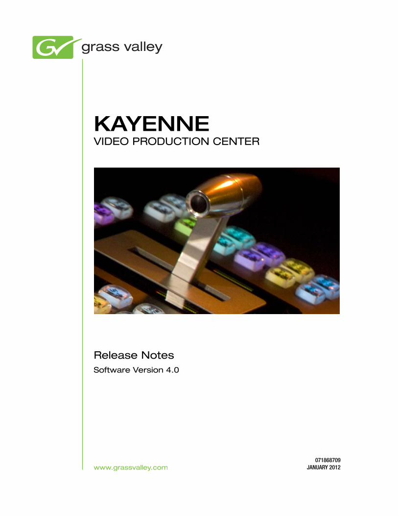
KAYENNEVIDEO PRODUCTION CENTER
Release NotesSoftware Version 4.0
071868709JANUARY 2012

CERTIFICATE
Certificate Number: 510040.001
The Quality System of:
Grass Valley USA, LLC and its Grass Valley Affiliates Headquarters: 400 Providence Mine Road Nevada City, CA 95945 United States
15655 SW Greystone Ct. Beaverton, OR 97006 United States
Brunnenweg 9 D-64331 Weiterstadt Germany
Kapittelweg 10 4827 HG Breda The Nederlands
2300 So. Decker Lake Blvd. Salt Lake City, UT 84119 United States
Including its implementation, meets the requirements of the standard:
ISO 9001:2008 Scope:The design, manufacture and support of video and audio hardware and software products and related systems.
This Certificate is valid until: June 14, 2012 This Certificate is valid as of: December 23, 2010 Certified for the first time: June 14, 2000
H. Pierre Sallé President KEMA-Registered Quality
The method of operation for quality certification is defined in the KEMA General Terms And Conditions For Quality And Environmental Management Systems Certifications. Integral publication of this certificate is allowed.
KEMA-Registered Quality, Inc.4377 County Line Road Chalfont, PA 18914 Ph: (215)997-4519 Fax: (215)997-3809 CRT 001 042108
Accredited By: ANAB

KAYENNEVIDEO PRODUCTION CENTER
Release NotesSoftware Version 4.0
071868709JANUARY 2012

4 KAYENNE — Release Notes
Contacting Grass Valley
Copyright © Grass Valley USA, LLC. All rights reserved.This product may be covered by one or more U.S. and foreign patents.
Grass Valley Web Site
The www.grassvalley.com web site offers the following:
Online User Documentation — Current versions of product catalogs, brochures, data sheets, ordering guides, planning guides, manuals, and release notes in .pdf format can be downloaded.
FAQ Database — Solutions to problems and troubleshooting efforts can be found by searching our Frequently Asked Questions (FAQ) database.
Software Downloads — Download software updates, drivers, and patches.
InternationalSupport Centers
France24 x 7 +800 8080 2020 or +33 1 48 25 20 20 United States/Canada
24 x 7 +1 800 547 8949 or +1 530 478 4148
Local Support Centers
(available during normal
business hours)
AsiaHong Kong, Taiwan, Korea, Macau: +852 2531 3058 Indian Subcontinent: +91 22 24933476Southeast Asia/Malaysia: +603 7805 3884 Southeast Asia/Singapore: +65 6379 1313China: +861 0660 159 450 Japan: +81 3 5484 6868
Australia and New Zealand: +61 1300 721 495 Central/South America: +55 11 5509 3443
Middle East: +971 4 299 64 40 Near East and Africa: +800 8080 2020 or +33 1 48 25 20 20
Europe
Belarus, Russia, Tadzikistan, Ukraine, Uzbekistan: +7 095 2580924 225 Switzerland: +41 1 487 80 02S. Europe/Italy-Roma: +39 06 87 20 35 28 -Milan: +39 02 48 41 46 58 S. Europe/Spain: +34 91 512 03 50Benelux/Belgium: +32 (0) 2 334 90 30 Benelux/Netherlands: +31 (0) 35 62 38 42 1 N. Europe: +45 45 96 88 70Germany, Austria, Eastern Europe: +49 6150 104 444 UK, Ireland, Israel: +44 118 923 0499

Contents
ContentsKayenne Release Notes . . . . . . . . . . . . . . . . . . . . . . . . . . . . . . . . . . . . . . . . . . . . . . . . . . 7
Introduction . . . . . . . . . . . . . . . . . . . . . . . . . . . . . . . . . . . . . . . . . . . . . . . . . . . . . . . . . . . 7Changes in Release 4.0 . . . . . . . . . . . . . . . . . . . . . . . . . . . . . . . . . . . . . . . . . . . . . . . . 7
New in Release 4.0 . . . . . . . . . . . . . . . . . . . . . . . . . . . . . . . . . . . . . . . . . . . . . . . . . . 7Improved in Release 4.0 . . . . . . . . . . . . . . . . . . . . . . . . . . . . . . . . . . . . . . . . . . . . . 7
DPM Borders . . . . . . . . . . . . . . . . . . . . . . . . . . . . . . . . . . . . . . . . . . . . . . . . . . . . . . . . . . 8Border Edge Adjustments . . . . . . . . . . . . . . . . . . . . . . . . . . . . . . . . . . . . . . . . . . . . . 8
Border Color . . . . . . . . . . . . . . . . . . . . . . . . . . . . . . . . . . . . . . . . . . . . . . . . . . . . . . . 9Separate Edges . . . . . . . . . . . . . . . . . . . . . . . . . . . . . . . . . . . . . . . . . . . . . . . . . . . . 10
Additive Keyers. . . . . . . . . . . . . . . . . . . . . . . . . . . . . . . . . . . . . . . . . . . . . . . . . . . . . . . 11Additive Keyer Operations . . . . . . . . . . . . . . . . . . . . . . . . . . . . . . . . . . . . . . . . . . . 11
From the Menu. . . . . . . . . . . . . . . . . . . . . . . . . . . . . . . . . . . . . . . . . . . . . . . . . . . . 12From the Control Panel . . . . . . . . . . . . . . . . . . . . . . . . . . . . . . . . . . . . . . . . . . . . . 13
SNMP Monitoring. . . . . . . . . . . . . . . . . . . . . . . . . . . . . . . . . . . . . . . . . . . . . . . . . . . . . 14Introduction . . . . . . . . . . . . . . . . . . . . . . . . . . . . . . . . . . . . . . . . . . . . . . . . . . . . . . . . 14Grass Valley Switcher Device Monitoring by SNMP. . . . . . . . . . . . . . . . . . . . . . 15
Video Processor Frame . . . . . . . . . . . . . . . . . . . . . . . . . . . . . . . . . . . . . . . . . . . . . 16Control Panel . . . . . . . . . . . . . . . . . . . . . . . . . . . . . . . . . . . . . . . . . . . . . . . . . . . . . 16Menu Panel Processor . . . . . . . . . . . . . . . . . . . . . . . . . . . . . . . . . . . . . . . . . . . . . . 16
SNMP Installation . . . . . . . . . . . . . . . . . . . . . . . . . . . . . . . . . . . . . . . . . . . . . . . . . . . 16SNMP Licensing . . . . . . . . . . . . . . . . . . . . . . . . . . . . . . . . . . . . . . . . . . . . . . . . . . . . 17
Licensing Definitions. . . . . . . . . . . . . . . . . . . . . . . . . . . . . . . . . . . . . . . . . . . . . . . 17SNMP Power Up License Processing . . . . . . . . . . . . . . . . . . . . . . . . . . . . . . . . . 18
SNMP Licensed Configuration . . . . . . . . . . . . . . . . . . . . . . . . . . . . . . . . . . . . . . . . 18Switcher Device SNMP Configuration Procedure . . . . . . . . . . . . . . . . . . . . . . 19
SNMP Trap Messages . . . . . . . . . . . . . . . . . . . . . . . . . . . . . . . . . . . . . . . . . . . . . . . . 19Video Processor Frame Traps . . . . . . . . . . . . . . . . . . . . . . . . . . . . . . . . . . . . . . . 20Control Panel Traps . . . . . . . . . . . . . . . . . . . . . . . . . . . . . . . . . . . . . . . . . . . . . . . . 21
Record Time Remaining Indicator for ClipStore . . . . . . . . . . . . . . . . . . . . . . . . . . . 22Kayenne Software Update . . . . . . . . . . . . . . . . . . . . . . . . . . . . . . . . . . . . . . . . . . . . . . 23
Introduction . . . . . . . . . . . . . . . . . . . . . . . . . . . . . . . . . . . . . . . . . . . . . . . . . . . . . . . . 23Third-party Updates . . . . . . . . . . . . . . . . . . . . . . . . . . . . . . . . . . . . . . . . . . . . . . . 23Materials Required. . . . . . . . . . . . . . . . . . . . . . . . . . . . . . . . . . . . . . . . . . . . . . . . . 23
Software Update Procedure. . . . . . . . . . . . . . . . . . . . . . . . . . . . . . . . . . . . . . . . . . . 24Backup Current Configuration and Effects Files . . . . . . . . . . . . . . . . . . . . . . . 24Replace Video Processor Frame Controller Board . . . . . . . . . . . . . . . . . . . . . . 24Deploy Switcher Update Package Files and Installer. . . . . . . . . . . . . . . . . . . . 24GV Switcher Installer Program Description . . . . . . . . . . . . . . . . . . . . . . . . . . . 28System Update (Video Processor Frame & Control Panels) . . . . . . . . . . . . . . 30Menu Panel Application Installation/Update. . . . . . . . . . . . . . . . . . . . . . . . . . 32Clear NV RAM for Control Panel and Frame . . . . . . . . . . . . . . . . . . . . . . . . . . 37Calibrate the Lever Arm and Joystick. . . . . . . . . . . . . . . . . . . . . . . . . . . . . . . . . 37Update Additional Menu Panels or PCs . . . . . . . . . . . . . . . . . . . . . . . . . . . . . . 37First Time Menu on PC Installation . . . . . . . . . . . . . . . . . . . . . . . . . . . . . . . . . . 37Soft Panel Installation . . . . . . . . . . . . . . . . . . . . . . . . . . . . . . . . . . . . . . . . . . . . . . 38NetConfig and Newton Configurator Installation . . . . . . . . . . . . . . . . . . . . . . 38Check Software Versions . . . . . . . . . . . . . . . . . . . . . . . . . . . . . . . . . . . . . . . . . . . 39Confirm System Operation. . . . . . . . . . . . . . . . . . . . . . . . . . . . . . . . . . . . . . . . . . 39
KAYENNE — Release Notes 5

Contents
Backup New Configuration and Effects Files . . . . . . . . . . . . . . . . . . . . . . . . . . 40Other Grass Valley Switcher Systems Software Update. . . . . . . . . . . . . . . . . . . 40Individual Switcher System Component Update . . . . . . . . . . . . . . . . . . . . . . . . 40Removing Switcher Software . . . . . . . . . . . . . . . . . . . . . . . . . . . . . . . . . . . . . . . . . 40
Menu Panel Application Removal . . . . . . . . . . . . . . . . . . . . . . . . . . . . . . . . . . . 40GV Switcher Deployment Tool Files Removal . . . . . . . . . . . . . . . . . . . . . . . . . 41Removing Using the Windows OS. . . . . . . . . . . . . . . . . . . . . . . . . . . . . . . . . . . 42
Kayenne System IP Addresses . . . . . . . . . . . . . . . . . . . . . . . . . . . . . . . . . . . . . . . . . . 42Default IP Addresses . . . . . . . . . . . . . . . . . . . . . . . . . . . . . . . . . . . . . . . . . . . . . . . . 42New Single Control Surface Kayenne Systems . . . . . . . . . . . . . . . . . . . . . . . . . . 43Multiple Control Surfaces and Suites . . . . . . . . . . . . . . . . . . . . . . . . . . . . . . . . . . 43
6 KAYENNE — Release Notes

Version 4.0JANUARY 2012
Kayenne Release Notes
IntroductionThis document describes installation, user, and other information specific to Kayenne Video Production Center Release 4.0 software. See page 23 for Kayenne system update instructions.
Changes in Release 4.0
New in Release 4.0• DPM Borders (see page 8)
• Additive Keyer (see page 11)
• SNMP (see page 14)
• Switcher Soft Panel (KSP) (see page 38)
• VDCP Protocol Support
Improved in Release 4.0
VxWorks Operating System
The VxWorks operating system replaces the Pharlap operating system used in the Kayenne Frame.
CAUTION Kayenne software earlier than version 4.0 is not compatible with VxWorks because the 771-0060-04 Controller Board is required. Backing down to version 3.0 will require changing back to the 771-0060-03 Controller Board.
Upgrading an existing Kayenne Frame to version 4.0 will require a Frame Controller Board Revision level of 771-0060-04 (see Replace Video Processor Frame Controller Board on page 24). Contact Grass Valley Customer Support for more information (see Contacting Grass Valley on page 4).
KAYENNE — Release Notes 7

Version 4.0
The new 771-0060-04 Controller Board CPU has 2 Gigabytes of memory, double that of the 771-0060-03 Controller Board.
Note E-MEMs and Macros are compatible (forward and backward) between Kayenne versions 3.0 and 4.0.
ClipStore “Record Time Remaining” indicator
See page 22.
DPM BordersThe DPM Border feature provides an independently controlled border for each licensed iDPM/eDPM. The borders are added "outside" of normal blanking. This means that when a border is added it does not crop into the original image so a border can be added to a full-sized image and it will not be visible until the image size is slightly reduced.
The following controls are provided from the menu for each DPM:
• Width and softness for border top, bottom, left and right side can be controlled independently or all together,
• Color (hue, saturation, and brightness),
• Choice of square or rounded border corners (including control of the curve tension, continuity, and bias), and
• S-Linear, Linear, Curve, and Path Hold.
Border Edge AdjustmentsTo adjust the border edges together, perform the following.
1. Access the Borders Menu by touching iDPM, Borders (Figure 1).
8 KAYENNE — Release Notes

DPM Borders
Figure 1. DPM Border Menu
2. Touch to select an ME/Keyer data pad on the left side of the menu (or use the Multi select button for multiple keyers).
Note DPMs selected for borders using the Multi select button will each have the same border values.
3. Turn on DPM Borders by touching either the Square Border or Round Border button in the Border Enable menu pane (Figure 1).
4. Select a path type by touching the S-Linear, Linear, or Curve data pads in the Border menu pane (Figure 1).
a. If Curve is selected, the Tension, Continuity, and Bias can be adjusted using the soft knobs or pop-up keypads.
See the Kayenne User Manual for more information about Paths.
5. Touch the Width or Softness data pads and use the Size or Softness soft knobs or pop-up keypads to adjust those values (Figure 1).
Border Color
Adjust the border color by touching the Border Color Adjust data pad (the color value is displayed in the data pad) and then turning the Border Hue, Border Saturation, or Border Brightness soft knobs or using the pop-up keypads to adjust those values (Figure 1).
KAYENNE — Release Notes 9

Version 4.0
Note Color is applied to the entire border, there is no independent control.
Separate Edges
The width and softness of DPM Borders can be adjusted for each edge inde-pendently, using the soft knobs or pop-up keypads (Figure 2).
1. Access the Borders Menu by touching iDPM, Borders.
2. In the iDPM (or eDPM in eDPM mode), Border menu, touch the Square Border or Round Border button to enable Borders (Figure 2).
Figure 2. DPM Border Menu, Separate Edges
3. Touch the Separate Edges button to enable the function.
4. Touch the Width or Softness data pad to select it.
5. Use the Border Size/Softness Top, Right, All, Left, or Bottom soft knobs or pop-up keypads to adjust the edges independently of the others.
Note The Border Size All/Softness All data pads allow you to adjust the relative values for size or softness of all edges simultaneously.
10 KAYENNE — Release Notes

Additive Keyers
Additive KeyersIn the keyer circuitry of the switcher, unshaped video is processed using a multiplicative key and shaped video is processed using an additive key. In the normal course of operation, this is done automatically. Shaped video can be turned on or off (unshaped video) for a source’s linear key in the Key Mode pane of the Eng Setup, Source Definition menu (Figure 3).
See the Kayenne User Manual for more information about Shaped and Unshaped video.
Figure 3. Eng Setup, Source Definition Menu
However, there are instances when manual control is useful:
• A source’s key is not properly defined and you wish to correct the shape by overriding the key type, or
• You wish to key an artistic effect by changing the video to the “incor-rect” video shaping.
Additive Keyer OperationsAdditive Keyer buttons, including a button for Super Additive are pro-vided in both the menu and in the Multi-Function Module of the Control Panel.
KAYENNE — Release Notes 11

Version 4.0
From the Menu
Additive Key and Super Add buttons are provided in the menu for Fixed and Adjusted Linear and Luma keys so you can override the video shape selected in the Source Definition menu (changes from Auto to On or Off) for that source.
In the menu, the Additive Key button is located in the Keyer, Mode menu (Figure 4).
Figure 4. Keyer, Mode Menu—Additive Key
Note Selecting or re-selecting any Keyer Mode button (Fixed Linear, Adj Linear, or Luma Key) will reset the shape type to “Auto”, i.e. as defined in the Source Definition menu.
1. Touch the desired Key.
2. In the Keyer Mode pane, touch the Fixed Linear, Adj Linear, or Luma Key buttons if not already selected.
3. Touch the Additive Key button to turn it to On (illuminates green).
4. Touch the Additive Key button again to turn it Off.
The key will remain in the selected On/Off state.
12 KAYENNE — Release Notes

Additive Keyers
Super Additive
“Super Additive” mode replaces the key signal of the selected source with a full field of black, while in the additive key mode. The opacity of the fine and semi-transparent video is greatly increased based on its luminance. This is very much a “fashion-statement” kind of keying which has been very popular with entertainment shows. Additionally, Super Additive mode is very useful for keying over credits and other text because it brightens and increases transparency.
When Additive Key mode is On, the Super Add button is displayed (Figure 5) and defaults to Off. Touch the Super Add button to turn it On/Off.
The Super Add button is also returned to “Auto” state by selecting or re-selecting a Keyer Mode button.
Figure 5. Keyer, Mode Menu—Additive Key/Super Add Button
From the Control Panel
In the Multi-Function Module of the Control Panel, the Add button is pro-vided in the Keyer (Keys) menu (press Keys, Add). For Super Add, DPOP the Add button (Add button changes from high tally white to high tally orange).
KAYENNE — Release Notes 13

Version 4.0
SNMP Monitoring
IntroductionSimple Network Management Protocol (SNMP) is an industry standard mechanism for monitoring devices over a network, primarily intended to support service and maintenance activity. With SNMP, devices can be inter-rogated about the current status of specific device components (reported as values), and devices can report without prompting (traps) certain condi-tions that may require immediate attention.
An SNMP system consists of one or more Managed Devices, each of which has an Agent (software running as a daemon on that device), and a Network Management System (NMS). The NMS is a software application running on a computer that communicates with the Agents over the net-work. The information exchanged is determined by a Management Infor-mation Base (MIB) database file. The MIB defines the structure and content of the variables that are available as data for monitoring and reporting. A Community Name is also used as a rudimentary security measure, acting as a password to enable communications with the Agent.
For example, a Managed Device may have a cooling fan and thermocouple. The MIB may define a variable for the thermocouple readout, and a request for this data can be sent from the NMS to the Agent, which will reply (if the community name matches) with the current temperature value. The MIB may also define a Trap that reports a fan failure. Should the device’s fan stop working, the Agent sends an unprompted message to the NMS. The NMS can be configured to respond to that Trap message, and may have the capability to alert maintenance staff of the problem, via an automatic email message or by triggering a warning alarm.
SNMP is an optional feature for Grass Valley switchers, and requires the purchase and entry of a license key.
The Grass Valley NetCentral application, separately available for purchase, can be used as a NMS. NetCentral version 5.2.0.24 is fully compatible with the Grass Valley switcher products. Because SNMP is an industry standard, however, any third party NMS can be used. For third party NMS installa-tion & configuration, please contact your SNMP NMS software vendor.
Grass Valley switchers comply with the following SNMP standards:
Table 1. SNMP Standards Supported
RFC 1155 Structure and Identification of Management for TCP/IP-based Internets
RFC 1157 SNMP v1
RFC 1901-1907 SNMP v2c
RFC 1213 MIB II
RFC 1215 Convention for defining traps for use with the SNMP
14 KAYENNE — Release Notes

SNMP Monitoring
The Grass Valley switcher MIBs are available from Grass Valley Customer Support. Load the MIBs for the Video Processor Frame and Control Panel as shown in Table 2.
Grass Valley Switcher Device Monitoring by SNMPGrass Valley switchers support monitoring of the devices and device com-ponents shown in the following tables.
Note Only the capabilities described in this document are supported. For detailed information about each supported item, please refer to the MIBs.
Table 2. Grass Valley Proprietary MIBs
MIB Description Video Processor Frame Control Panel
gvg-reg last updated "200402190000Z" X X
gvg-element last updated "200503230000Z" X X
gvg-gcp last updated "200503240000Z" X
gvg-vsm last updated "200503240000Z" X
KAYENNE — Release Notes 15

Version 4.0
Video Processor Frame
Control Panel
Menu Panel Processor
The Menu Panel Processor (the PC running the Menu application) can be monitored separately, using the standard built-in Windows SNMP capabil-ities and a third-party NMS. No unique Grass Valley MIB entries or traps are available.
Note NetCentral supports the monitoring of Grass Valley devices only, and cannot directly monitor standard PCs.
SNMP InstallationGrass Valley switchers system devices running version 4.0 and higher soft-ware have SNMP Agent software already installed. No user installation is required.
Separate NMS software (NetCentral or a different third party package) will need to be installed onto a PC that resides on the switcher network. Refer to the documentation provided with the NMS for installation instructions.
Table 3. Supported Karrera/Kayenne Video Processor Frame SNMP Monitoring
System Information High level information regarding the Video Processor Frame including operating system, name, location, serial number, software revision and high level frame state.
Module Each plug in board slot in the Frame is a module (Controller, ME or eDPM). Information is provided regarding the board plugged into the slot and the current state of the slot.
Thermal High level temperature and fan status for the entire system. If a failure is reported here then look at Fans or Temperature Sensor categories for details.
Fans Detailed speed and status for each fan in the frame. Three fans are on the compact frame and six fans are on the standard frame. Typically inspected if Thermal category is report-ing a cooling problem.
Temperature Sensors Detailed information from each monitored temperature sensor on the Frame. Typically inspected if Thermal category is reporting a cooling problem.
Video Sync Status of external video reference signal and what type of signal is present.
Network Configuration Data IP address, Gateway and Netmask settings for external facing network interfaces.
Table 4. Supported Kayenne/Karrera Control Panel SNMP Monitoring
Fan (1- 3) Kayenne: PCU has three fans.Karrera: 2ME Control Panel has one fan, 3 ME has two fans.
Power Supply (2) Will report power failure if a power supply is not present or not plugged in.
Temperature (2 or 3) Kayenne: One ambient temperature, one on CPU.Karrera: One ambient temperature, one on the Panel Processor FPGA, one on CPU.
Modules (Control Panel boards) Status change traps are sent when a module is connected or disconnected.
16 KAYENNE — Release Notes

SNMP Monitoring
SNMP LicensingGrass Valley switcher system SNMP licensing is based on the Video Pro-cessor Frame, and is tied to that Frame’s unique System ID number. All Control Panels associated with a Frame will use that same SNMP license.
The Frame’s System ID is shown on the Menu application’s Install Options screen This screen also reports the current licensing status of that Frame (Figure 6).
Figure 6. Install Options Screen
An SNMP license is purchased from Grass Valley Customer Support. You need to provide the Frame’s System ID with your payment, and you will then be given a license key. Enter that license key in the Install Options screen to license the SNMP feature for that entire Kayenne system.
Licensing Definitions
SNMP Licensed - SNMP is capable of running with all documented features available. See SNMP enable/disabled for additional operational implica-tions.
SNMP Unlicensed - SNMP runs minimal functionality provided by the oper-ating system vendor (VxWorks on 4.0 Kayenne frames, Linux on Kayenne Control Panels) and is always enabled.
KAYENNE — Release Notes 17

Version 4.0
SNMP Enabled - (licensed only) all SNMP variable requests are processed and SNMP traps are sent.
SNMP Disabled - (licensed only) all SNMP variable requests are ignored and SNMP traps are not sent.
SNMP Power Up License Processing
Frames and Control Panels power up with SNMP Unlicensed capabilities. If a SNMP license is detected on the Frame then the Frame and Control Panel initialize SNMP licensed capabilities. SNMP Licensed Configuration must be done to properly configure some of the licensed capabilities.
SNMP Licensed ConfigurationSNMP Licensed capabilities require additional configuration though the web interface as noted in this document. The Video Processor Frame and Control Panel have separate web interfaces that are accessed by specifying the correct IP address in the URL (example: http://192.168.1.170). An example of the Kayenne Frame webpage is shown in Figure 7.
Configuration steps consist of:
• Enable/Disable SNMP
• Configure Trap Destination IP addresses
• Configure Community Name
Configuration of the NMS software itself will also be required to make full use of the SNMP feature.
18 KAYENNE — Release Notes

SNMP Monitoring
Figure 7. Video Processor Frame SNMP Web Page
Switcher Device SNMP Configuration Procedure
Refer to Figure 7 for reference.
1. Check the Enable/Disable box to activate SNMP for that device.
Note SNMP configuration fields are inoperable (grayed out) if a valid license is not accessible.
2. Enter the IP address of the PC running a NMS where you want trap messages to be sent. Up to three IPs can be entered.
3. If you are not using the public community, enter the name of the community to be used.
4. Click Save New Settings.
SNMP Trap MessagesThe SNMP trap messages listed below are available for various switcher system components.
Note Only the capabilities described in this document are supported. For detailed information about each supported item, please refer to the MIBs.
KAYENNE — Release Notes 19

Version 4.0
Video Processor Frame Traps
Table 5. Supported Kayenne/Karrera Frame SNMP Traps
Name Type Description Severity
vsmPowerSupplyStatusChange status If the current status is different than the last status then a trap is sent. A power supply OK message is only sent if all power supplies are OK after one of more power supplies have failed or been removed. At boot time, the first running status generates an informational message. After that, a transition to the running status generates a normal message.
comm error = alarmfault = alarmpower supply removed = warning power supply OK = normal
vsmFanStatusChange status If the fan board is not present or if all fans have stopped working a trap is sent. This trap is resent every 12 seconds until the condition is corrected.
If any of the fans are not working properly a trap is sent. This trap is resent every 20 sec-onds until the condition is corrected.
When the system starts running normally or returns from an abnormal condition to running normally a trap is sent.
fan board not present = alarmall fans not working = alarmfan not working = warning
normal operation = informational (start up),normal (returning from a warning or alarm condition)
vsmTempStatusChange status If temperature crosses the warm threshold in any direction a trap is sent.
hot = alarmnormal = normal
vsmModuleStatusChange powerOK If the current power status is different than the last power status a trap is sent.
power OK = normalpower Fault = alarm
vsmModuleStatusChange status If the current status is different than the last status a trap is sent.
operational = normalfailed = alarmnot inserted = warning
vsmReferenceStatusChange status When the video reference transitions between locked and not locked in either direction a trap is sent.
not locked = warninglocked = normal
gvgElStateChange status When the switcher starts the boot process and the trap status is “initializing” a trap is sent.
Another trap is sent when the switcher becomes fully operational and the trap status is “running”.
initializing = warning running = normal
20 KAYENNE — Release Notes

SNMP Monitoring
Control Panel Traps
Table 6. Supported Kayenne/Karrera Control Panel Traps
Name Type Description Severitya
a Severity Levels: EGvgAlarm = 6, EGvgWarning = 5, EGvgNormal = 4
gcpUnknown(1) Panel Status Change
NOTE: This value can be a bit-wise ORing of the enumerated states. When a faulty state is fixed the corresponding bit in the value gets cleared.
The panel is in an unknown state, or does not possess enough intelligence to report its state.
normal
gcpOk(2) The panel is connected to the equipment it is controlling and is operating normally.
normal
gcpCommunicationError(4) The panel is unable to communicate with the equipment that it is controlling.
alarm
gcpMainPowerFault(8) The Main power supply on the controller was removed, got dis-connected from the ac line, or was faulty.
alarm
gcpRedundantPowerFault(16) A redundant power supply on the controller was removed, got dis-connected from the ac line, or was faulty.
warning
gcpFanFault(32) The panel has detected a fault on one or more cooling fans.Karrera has up to two fans, Kayenne PCU has three fans.
warning
gcpThermalFault(64) The temperature in the panel is too high for reliable operation. warning
gvgElementRunning (1) Device Status Change The element is running and processing load. NA
gvgElementInitializing(6) This is a post bootstrap state where the element has been restarted, and is initializing its hardware and software components.
NA
gvgElementHalted(8) The element has halted and not processing load. NA
gcpModStateUnknown(1) Module Status Change The module is in an unknown state. normal
gcpModRunning(2) The module is running OK. normal
gcpModRemoved(4) The previously installed hot-swappable module has been removed.
alarm
gcpModCommError(9) The system is unable to communicate with the module. alarm
KAYENNE — Release Notes 21

Version 4.0
Record Time Remaining Indicator for ClipStoreA Record Time Remaining indicator in HH:MM:SS format is provided in ClipStore as a reminder to maintain enough storage space for recording or adding clips. The indicator, located in the Image Store, Replay & Record menu (bottom left of the Clips scrolling window), displays the available storage remaining in the ClipStore Summit/Solo server (Figure 5).
Note The Record Time Remaining indicator is only available in the Clips and Clip Record and Edit tabs.
Figure 8. ClipStore “Record Time Remaining” Indicator
Record Time Remaining Indicator
22 KAYENNE — Release Notes

Kayenne Software Update
Kayenne Software Update
IntroductionKayenne systems are shipped with the current software version installed. Updates to Kayenne system software are available for download from the Grass Valley website. Software installation tools are provided with each update package.
The GV Switcher Deployment Tool extracts and copies Grass Valley switcher system files to a Menu Panel or PC. These files include the GV Switcher Installer Program.
The GV Switcher Installer Program is used to install the extracted software to Grass Valley Video Processor Frame(s) and Control Panel(s) over the net-work. The GV Switcher Installer Program also launches other installation tools (wizards). One wizard installs the Menu application directly on the Menu Panel or PC running the installer program. If multiple Menu Panels (or PCs running the Menu application) exist, each must be updated indi-vidually. Installation wizards can also be launched for the KSP and Net-Config features.
Third-party Updates
A directory, named “Third-party Updates” is provided as a convenience on the Grass Valley software download site and is included on the Switcher Software USB Memory Stick shipped with each Grass Valley switcher system. The directory contains third-party files and libraries to help recon-cile any version issues that may develop between Grass Valley products and third-party applications.
Materials Required
You will need the following materials for this update:
• New Video Processor Frame Controller board (771-0060-04),
• Version 4.0 Software; GVSwitcherSetup.exe, which can be downloaded from the Grass Valley Customer Support website along with the latest ClipStore/Summit software, Release Notes, and Release Notes Addendum, and copied to a USB stick,
• Backup media for configuration and effects files,
• USB mouse and keyboard, and
• a Menu Panel, or user PC, properly configured on the switcher system network.
KAYENNE — Release Notes 23

Version 4.0
Software Update ProcedureThis software update procedure assumes your Grass Valley switcher system is fully operational with all network communications properly con-figured. Refer to the Kayenne Installation and Service Manual for configura-tion instructions.
Backup Current Configuration and Effects Files
1. Save your system configuration files (Eng Setup, User Setups), and your operational registers (EMEM, Macros, etc.) and other settings. You can create a Show file that contains all this information. See the Kayenne Installation and Service Manual for file operations instructions.
Note A convenient location to save these backup files is on the USB stick of the software version that created the files (the older software being updated). Create a new folder on that older software USB stick for the file and name the Show file with the current date.
2. Store the backup media in a safe place. You may want to use these files if you decide to back down to that earlier software version.
Replace Video Processor Frame Controller Board
1. Go to the Eng Setup Frame Suite Nodes & ID and Control Surfaces Node Settings menu tabs and write down all the current network node names and IP addresses. These will need to be re-entered manually after the controller board has been replaced.
2. Power off the Video Processor Frame.
3. Remove the older controller board (771-0060-03 or lower).
4. Insert the new controller board (771-0060-04 or higher).
5. Power up the Video Processor Frame. The Video Processor Frame will reboot with the same IP address.
6. Re-enter the Eng Setup Node Settings you recorded earlier.
Deploy Switcher Update Package Files and Installer
1. Exit the Menu application and any other applications, that may be running on the Menu Panel or PC.
2. Disable any virus protection, Windows firewall, and any other firewall protections that may have been installed on the Menu Panel or PC. Firewalls must be inactive to allow switcher system software installation over the network.
24 KAYENNE — Release Notes

Kayenne Software Update
3. Insert the GV Switcher Software USB stick into an available port on the Menu Panel or PC.
4. Locate the removable disk in My Computer and double-click on the GVSwitcherSetup.exe and click OK. Screens will appear as the files are extracted and the GV Switcher Deployment Tool is installed (Figure 9).
Figure 9. File Extraction Screens
Note If the same GV Switcher Deployment Tool version files are detected, a Repair/Remove screen is displayed, allowing re-installation or removal of the Deployment files.
5. The GV Switcher Deployment Tool will then launch (Figure 10).
Figure 10. GV Switcher Deployment Tool Initial Screen
KAYENNE — Release Notes 25

Version 4.0
6. Click Next. The License Agreement screen appears (Figure 11).
Figure 11. GV Switcher Deployment License Agreement
7. Accept the license and click Next. The Destination Folder screen appears (Figure 12).
Figure 12. GV Switcher Deployment Destination Folder
26 KAYENNE — Release Notes

Kayenne Software Update
8. Click Next to accept the default deploy location. Alternatively, you can Browse to a different location to deploy the files to. The Ready to Deploy Screen appears next (Figure 13).
Figure 13. Ready to Deploy Screen
9. Click Next to deploy the files. A progress bar will be displayed (Figure 14).
Figure 14. GV Switcher Deployment Update Status Screen
10. When the deployment completes the GV Switcher Installer Program will launch automatically (Figure 16).
After the switcher files have been deployed, the GV Switcher Installer Program can be launched at any time by clicking on its desktop icon (Figure 15).
Figure 15. Installer Icon
KAYENNE — Release Notes 27
Version 4.0
GV Switcher Installer Program Description
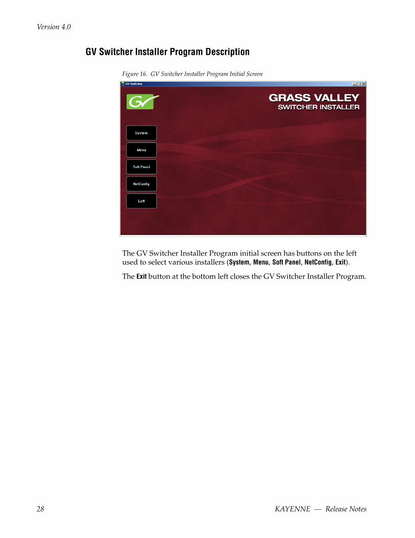
Figure 16. GV Switcher Installer Program Initial Screen
The GV Switcher Installer Program initial screen has buttons on the left used to select various installers (System, Menu, Soft Panel, NetConfig, Exit).
The Exit button at the bottom left closes the GV Switcher Installer Program.
28 KAYENNE — Release Notes

Kayenne Software Update
When System is selected, a screen appears with an expandable central hier-archy window, information on the upper right, and function buttons on the lower right (Figure 17).
Figure 17. GV Switcher Installer Program Expanded Hierarchy Window
System Devices is at the top of the hierarchy window. Clicking on that item displays the types of switchers (Kayenne and/or Karrera) residing on the net-work. Clicking on a switcher type displays the system names present on the network of that switcher type. Each system name is taken from the Video Processor Frame name. Clicking on a system name reveals Frame and Panel items for that system, which when opened allows selection of the indi-vidual Frame and Panels making up that system. When a specific device is selected, information for it is displayed on the right. This hierarchy allows easy identification of each switcher system’s components when multiple switchers reside on the same network.
The GV Switcher Installer program has the following other features, accessed by clicking on its labeled button:
Rescan - Re-scans the network for devices. This refreshes the screen to show the currently connected components and any modified system names.
Update - Updates the software on the selected device using the software deployed with this GV Switcher Installer version.
Set Name - Opens a window allowing you to change the name of the selected device.
Set Server - (Control Panel selected in hierarchy window) - Opens a window allowing you to enter the IP address the Control Panel will use to commu-nicate with the Video Processor Frame.
KAYENNE — Release Notes 29

Version 4.0
Clear NV - (Frame or Control Panel selected) Clears NV Memory.
Update All - (System selected) Updates software to all devices for the selected system, excluding Menus.
Create CF - Allows the duplication of a Frame or Control Panel Compact Flash Card onto another CF Card.
System Update (Video Processor Frame & Control Panels)
1. With the GV Switcher Installer Program launched, click on the System button. A screen similar to Figure 18 appears.
Figure 18. GV Switcher Installer, System Button Selected
30 KAYENNE — Release Notes

Kayenne Software Update
2. Each Kayenne system consists of a Video Processor Frame and associated PCU(s) (Control Panels). Use the mouse to navigate to the desired system (not an individual Frame or Panel). When a system has been selected the Update All button becomes active (Figure 19).
Figure 19. GV Switcher Installer, Kayenne System Chosen
3. Click Update All. The following reboot message appears (Figure 20).
Figure 20. GV Switcher Installer, Reboot Screen
4. If the Reboot when complete box is checked, the Video Processor Frame and all associated Control Panels will automatically reboot after the software update. If the box is not checked, you will need to manually reboot the Video Processor Frame after the software files have finished being transferred to them. Control Panels are always rebooted after a software update.
KAYENNE — Release Notes 31

Version 4.0
5. Click OK. The screen will report the progress of the update (Figure 21).
Figure 21. GV Switcher Installer, Update Progress
6. While finishing the update, and the components reboot, an Updating screen appears (Figure 22). The Control Panel and Video Processor Frame will be operational when complete.
Figure 22. GV Switcher Installer, Updating
7. Click Finish to exit the screen.
Menu Panel Application Installation/Update
The GV Switcher Deployment Tool must be run on each Menu Panel or PC onto which you will be installing the Menu Panel application. See Deploy Switcher Update Package Files and Installer on page 24.
CAUTION For Menu on PC, you must be logged on as administrator or the installation will fail.
1. Click on the GV Switcher Installer desktop icon (Figure 23), if necessary, to launch the GV Switcher Installer Program (Figure 24).
Figure 23. Installer Icon
32 KAYENNE — Release Notes

Kayenne Software Update
Figure 24. GV Switcher Installer Program Initial Screen
2. Click the Menu button. The GV Switcher Menu Installation tool will launch (Figure 25).
Figure 25. GV Switcher Menu Installer
KAYENNE — Release Notes 33

Version 4.0
3. Click Next. The Hardware Selection screen appears (Figure 26).
Figure 26. GV Switcher Menu Installer, Hardware Selection
4. In the Kayenne area, choose either Kayenne Menu Platform (the Kayenne Touch Screen Menu Panel), or User PC, as appropriate, and click Next.
Note The first-time installation of the Menu application onto a user PC may require installing Windows .NET Framework software. See First Time Menu on PC Installation on page 37 for more information.
5. The User Information screen appears next (Figure 27).
Figure 27. GV Switcher Menu Installer, User Information
6. Enter a name and organization, leave the Anyone who uses this computer setting selected, and click Next. The Destination Folder screen appears next (Figure 28).
34 KAYENNE — Release Notes

Kayenne Software Update
Note Selecting Only for me limits some settings to the currently logged in user. This may be appropriate if the Menu application is installed onto a PC shared by several users. However, this is not a fool-proof security method and should not be relied on for mission-critical applications.
Figure 28. GV Switcher Menu Installer, Destination Folder
7. Click Next to accept the default installation location. Alternatively, you can Browse to a different location to install the application. The Ready to Install Screen appears next (Figure 29).
Figure 29. GV Switcher Menu Installer, Ready to Install
KAYENNE — Release Notes 35

Version 4.0
8. Click Next to install the application. A progress bar will be displayed (Figure 30).
Figure 30. GV Switcher Menu Installer, Update Status Screen
9. When done, the Menu Successfully Installed screen appears (Figure 31).
Figure 31. GV Switcher Menu Installer Success
10. Click Finish to exit the GV Switcher Menu Installer tool.
11. Click Exit and answer Yes to the prompt to exit the GV Switcher Installer.
Clicking on the GV Switcher Menu icon (Figure 32) now launches the new version of the Menu Panel application.
Figure 32. Switcher Menu Icon
36 KAYENNE — Release Notes

Kayenne Software Update
Clear NV RAM for Control Panel and Frame
It is recommended that the NV RAM for the Control Panel and Frame be cleared after a software update.
From the GV Switcher Installer menu, touch the System button and touch the device to be cleared. Touch the Clear NV button (Figure 19 on page 31). Repeat for Control Panel and Frame.
Calibrate the Lever Arm and Joystick
It is recommended that the Kayenne Control Panel Lever Arm (for each Transition Module) and Joystick be calibrated after a software update.
Lever Arm Calibration (Transition Modules)
To calibrate a Lever Arm, press and hold down the two left (Exchange ME/Ptn Limit) and two right (EMEM Run/Trans Rate) buttons located just above the Lever Arm. Follow the instructions on the Transition Module status dis-play.
JoyStick Calibration (Multi-Function Module)
To calibrate the Joystick on the Multi-Function Module, from Home, press Panl, Cali and follow the instructions on the status display.
Update Additional Menu Panels or PCs
Follow the procedure above on every Menu Panel and PC running the Menu Panel application that operates with the updated Video Processor Frame.
Note A new Menu Panel or PC that has not been used with the switcher system will need to be configured as a Control Surface Node before it can operate with a switcher system. See the Kayenne Installation and Service Manual for specific instructions.
First Time Menu on PC Installation
The Windows .NET Framework software is required for Menu on PC appli-cation operation. If the correct version of this software is not present on the PC, a message will be displayed indicating it must be installed. This frame-work software is included on the GV Switcher Software USB stick, and on the Grass Valley website.
1. Insert the GV Switcher Software USB stick into the PC’s USB port.
KAYENNE — Release Notes 37

Version 4.0
2. Open the Third-party Updates folder, and in the DotNet 3.5 folder run the dotnetfx35.exe file. Files will be extracted to your PC and then the .NET Framework Setup application will run. Accept the license agreement and click Install.
3. When done, the message Download complete. You can now disconnect from the Internet will be displayed. Exit the .NET installer application and relaunch the GV Switcher Installer Program.
4. You will now be able to install the Menu application onto the PC (see Menu Panel Application Installation/Update on page 32).
5. Add the PC’s Name and IP Address with the Menu on PC software to the node list in the Eng Setup, Control Surfaces menu. For more information, see the Kayenne Installation & Service Manual.
Soft Panel Installation
Clicking on the Soft Panel button launches an individual installer for the KSP option. This installer is similar to the Menu Panel installer, and is intended for customer provided PC (not a Menu Panel). Follow the directions dis-played to install KSP onto that PC.
Soft Panel requirements:
• .net 4.0
• 1920x1080 display resolution
Add the PC’s Name and IP Address with the KSP software to the node list in the Eng Setup, Control Surfaces menu.
The KSP option is activated with a purchased license key.
NetConfig and Newton Configurator Installation
Clicking on the NetConfig button launches an individual installer similar to the Menu Panel installer. Both NetConfig and the Newton Configurator plug-in will be installed. Follow the directions displayed to install these applications onto that Menu Panel or PC.
Note The GV Switcher Installer Application and the separate NetConfig application cannot run simultaneously on the same Menu Panel or PC.
38 KAYENNE — Release Notes

Kayenne Software Update
Check Software Versions
Launch the Menu application. The Status Menu will list the switcher system devices. Ensure all the components are running the same software version. Mismatched versions will be reported with red text (Figure 33).
Figure 33. Mismatched Software Versions
Confirm System Operation
1. Check that all the installed MEs are operational. Select different crosspoints on the Control Panel and fly a key with an iDPM.
2. Check that any software enabled options operate correctly. Existing authorization codes should work with the new software.
3. Check that EMEMs run properly. Older effects should work with the new software. If there are differences, however, you will need to edit or rebuild the effect with the new software version.
4. Reload the Macros and check that they operate correctly.
5. Load some Image Store images and confirm they display correctly.
KAYENNE — Release Notes 39

Version 4.0
Backup New Configuration and Effects Files
1. When you are satisfied with system operation, save the new configuration files and effects as a Show file to a folder you’ve created on that version’s GV Switcher Software USB stick.
2. Label the media with the version and date and store it in a safe place.
3. Reactivate any virus protection on the Menu panel that may have been disabled at the start of this procedure.
This completes the standard switcher system software update procedure.
Other Grass Valley Switcher Systems Software UpdateMore than one switcher system (multiple Video Processor Frames) may reside on your network. Each system can operate simultaneously with dif-ferent software versions, as long as all the components in each system run the same software version.
Additional switcher systems are updated using the same procedure described before.
1. Select the other switcher system on the GV Switcher Installer Program System hierarchy screen, and choose Update All.
2. Insert the GV Switcher Software USB stick into each Menu Panel or PC associated with that switcher system and choose the Menu software update button.
Individual Switcher System Component UpdateIndividual components can be selected for update (just the Video Processor Frame, or just one Control Panel). However, all components of a switcher system must run the same software version. If updating components indi-vidually, make sure they all are at the same version before resuming Kayenne system operation.
CAUTION Allow the Video Processor Frame to completely finish rebooting before attempting to install Control Panel software. The Control Panel update process requires the Frame to be operational.
Removing Switcher Software
Menu Panel Application Removal
Running the GV Switcher Installer and clicking on the Menu button when that same version of Menu Panel software is already installed opens a
40 KAYENNE — Release Notes

Kayenne Software Update
Repair/Remove screen (Figure 34). Selecting Remove uninstalls the applica-tion from the Menu Panel or PC.
Figure 34. GV Switcher Menu Panel Application Removal
GV Switcher Deployment Tool Files Removal
The GV Switcher Deployment Tool package can be removed from the Menu Panel or PC by inserting a GV Switcher Software USB stick con-taining the same version package. A Repair/Remove menu appears, allowing reinstallation (repair) or removal of the deployment files (Figure 35).
Figure 35. Deployment Tool Removal
Deployment Archive Files
When new software versions are installed with the GV Switcher Deploy-ment tool, older version deployment files are not automatically removed.
KAYENNE — Release Notes 41

Version 4.0
Each GV Switcher deployment creates its own software version folder. If the default installation location, or the same alternative destination, is always chosen, all the version folders will be listed together (default desti-nation: C:ProgramFiles/Grass Valley/GV Switcher/GVSwitcherSystem_Vx.x.x). Running the KayenneInstaller.exe file in any version’s folder will permit installation of that version’s Kayenne files.
CAUTION Before installing an older version of the Menu Panel application, you must first un-install the newer, currently installed Menu Panel version, either using that newer version’s GV Switcher Deploy Tool or Windows Add/Remove Pro-grams. This also applies to Macro Editor installations.
Note All the components of a switcher system must run the same software ver-sion. If you want to return to an earlier version of software, you should back-down the software on the Video Processor Frame, all Control Panels, and all Menu Panel applications used with that switcher system.
Removing Using the Windows OS
GV Switcher Deployment Tool versions and Menu Panel programs can also be removed using standard Windows techniques (Setup/Add or Remove Programs).
Kayenne System IP Addresses
Default IP AddressesKayenne systems are shipped with default IP addresses (Table 7). These default addresses can be used if the Kayenne system is operating on a ded-icated network with no other devices present. Note that these addresses can be changed during installation, and so your system may not be using these defaults,
Table 7. Kayenne System Default IP Addresses
Device IP Address
Video Processor Frame CPU 192.168.0.170
Image Store CPU 192.168.0.171
Control Panel Surface 1A 192.168.0.173
Touch Screen Menu Panel 1 192.168.0.175
Touch Screen Menu Panel 2 192.168.0.176
Control Panel Surface 1B 192.168.0.177
Control Panel Surface 2A 192.168.0.178
Control Panel Surface 2B 192.168.0.179
ClipStore Server 192.168.0.180
42 KAYENNE — Release Notes

Kayenne System IP Addresses
New Single Control Surface Kayenne SystemsA new Kayenne system will operate on an isolated network with the default IP addresses configured at the factory (except for 32 Crosspoint Remote Aux panels). However, if you wish to integrate the Kayenne system into an existing network, wish to use gateway communications, or wish to add more Kayenne control surface components, IP addresses may need to be changed and Node lists updated accordingly.
Multiple Control Surfaces and SuitesIf you plan to use multiple control surfaces (for example, more than one Control Panel or more than one Menu Panel) with the same Video Pro-cessor frame, you must make sure the IP addresses of the additional items are unique before connecting them to the network. Using default IP addresses will cause network conflicts and unpredictable system opera-tion.
See the Kayenne Installation and Service Manual for specific information about network configuration.
32-Crosspoint Remote Aux PanelsV1.6.5 and higher software: (hard reset with the front panel buttons)
IP Address: 192.168.1.2Frame IP: 192.168.1.1Gateway IP: 192.168.1.1Subnet Mask 255.255.255.0,
Note 32-Crosspoint Remote Aux Panel default settings must be changed to operate with a Kayenne system whose other components are configured with their default IP addresses.
All Subnet Masks) 255.255.255.0
All Gateways(except V1.6.5 software Remote Aux panel)
192.168.0.1
Reserved For Future Use CAUTION Do not connect any devices configured with the fol-lowing IP addresses to a Kayenne network.
Video Processor Frame Gigabit Ethernet 192.168.0.172
PCU Panel Reserved LAN Port 192.168.0.174
Table 7. Kayenne System Default IP Addresses - (continued)
Device IP Address
KAYENNE — Release Notes 43

Version 4.0
44 KAYENNE — Release Notes


![[XLS]mibadas.files.wordpress.com · Web view1.0 2.0512134E7 4.0 2.0 2.0512134E7 4.0 3.0 2.0512134E7 4.0 4.0 2.0512134E7 4.0 5.0 2.0512134E7 4.0 6.0 2.0512134E7 4.0 7.0 2.0512134E7](https://img.dokumen.tips/doc/110x75/5b47d83b7f8b9af5078c58b1/xls-web-view10-20512134e7-40-20-20512134e7-40-30-20512134e7-40-40.jpg)