Embed Size (px)
Citation preview

Pieklak K., Mikołajczyk Z.; Original Concept of a New Multicomb Warp-knitting Machine for Manufacturing Spatial Knitted Fabrics. FIBRES & TEXTILES in Eastern Europe 2009, Vol. 17, No. 3 (74) pp. 76-80.
76
as well as no warp-knitting machines equipped with more than two needle combs.
The situation mentioned above inspired the authors to create a new innovative concept of a technology for manufactur-ing such spatial 3D - solids as knitted fabrics, which could be applied prima-rily for the production of technical tex-tiles [6]. Our proposition in no way limits the application of this patented technolo-gy for the manufacturing of other groups of knitted fabric assortments.
Concept of the structure of the warp-knitting machine
A warp-knitting machine with a number of needle combs greater than two for manufacturing spatial knitted products in the shape of geometrical solids can be equipped with an even or odd number of needle combs. The number of needle combs and the essential features of their structure precisely determine the shape of the product manufactured. A warp-knitting machine has a preliminary as-sumed number of needle combs as well as a number of basic and edge needle bars. As an analogy to one– and two-comb flat rashel warp-knitting machines, the needle combs can be equipped with tube needles, bearded needles, latch nee-dles, or shedding needles.
Similar to classical constructions of warp-knitting machines, a machine with a number of needle combs greater than two is equipped with holding sinkers and knocking –down combs. During the lifting motion of the needle combs, the holding sinkers hold the loop previous-ly formed. The knocking–down combs form a closed external channel in which subsequently formed loops of the exter-
nal layers and the threads of the internal layer are taken-up.
The way of feeding threads is already known from the structure of warp-knit-ting machines. Considering the structure of a warp-knitting machine designed for manufacturing spatial knitted products in the shape of geometrical solids, we ana-lysed the possibility of negatively feeding thread but with the active aid of winding threads from warp beams by using using spring or pneumatic compensators. Feed-ing the knitting zone with thread from creeling frames is an alternative solution. In the structure of a warp-knitting ma-chine with the number of needle combs greater than two, we designed an entirely different way of taking up the knitted fab-ric. The reason for this is that the product has a spatial form with a thickness of tens to hundreds of millimetres.
The warp-knitting machine described in this work is devoted to manufacturing spatial products in the shape of geometri-cal solids, in which we can identify two variants of driving the loop forming ele-ments:n the mechanical drive of lifting the
needles, needle bars and sinkers;n the mechanical-electric drive based
on individual drives of the particu-lar element realised with the use of a linear step motor.Special optimisa-tion of the machine construction can be undertaken to use joined hybrid drives which connect the mechanical solutions with the electronic systems controlled by servo-motors.
A significant feature of this group of warp-knitting machines is their working speed, which, according to the author’s concept, should be of a value within the range of 100 ÷ 150 spatial courses
Original Concept of a New Multicomb Warp-knitting Machine for Manufacturing Spatial Knitted Fabrics
Katarzyna Pieklak, Zbigniew Mikołajczyk
Technical Universty of ŁódźDepartment of Knitting Technology
and Structure of Knitted Fabricsul.Żeromskiego 116, 90-924 Łódź, Poland
e-mail: [email protected]@p.lodz.pl
AbstractThis article presents an original concept of warp-knitting machine construction with more than two needle combs. The technical and technological parameters of the warp-knitting machine with even and odd numbers of needle combs were characterised. The geometry of mutual positions of the basic machine elements were determined including the needle combs, needle bars and the holding sinker combs in relation to the knocking-down combs. A concept of the whole structure of the machine is presented, as well as the structure of the hybrid drives of the loop forming elements, devices feeding the threads, the take–up devices and storage parts for the spatial knitted fabrics.
Key words: warp-knitting machine, multi-comb, spatial knitted fabrics, structure concept.
n IntroductionTechnologies for manufacturing spa-tial distance three and five layer knitted fabrics are already known. Such knit-ted fabrics are manufactured with the use of warp-knitting machines equipped with two frontal and two back needle combs which are placed mutually par-allel in such a way that the needles are positioned opposite each other and their hooks directed outwards. Changes in the distance x between the needle combs determines the thickness of the knitted fabric manufactured. In most cases two-comb warp-knitting machines are used with six needle bars, four of which form external layers (two on each side) and two needle combs form one or two inter-nal layers of the knitted fabric. With the use of this group of machines, it is also possible to manufacture circular knitted fabric structures.
Left-right relief structures manufac-tured using the wale micromesh weave technology can also be included in the group of spatial knitted fabrics. These structures are characterised by small de-pressions and protrusions which indicate the three-dimensional character of this product. However, scientific and univer-sity literature do not regard this group of knitted fabrics as having a 3D structure.Warp-knitting machines are used in clas-sical technologies with one flat or cir-cular needle comb or with a maximum of two needle combs for manufacturing rib stitch products. The needle combs in these machines work in convertible sys-tems, where the needle bars are driven in a pendulous way.
A review and analysis of scientific and patent literature carried out by us indi-cated that no other 3D structures exist,

77FIBRES & TEXTILES in Eastern Europe 2009, Vol. 17, No. 3 (74)
per minute. This range is primarily lim-ited by the complexity of the motion of loop forming elements, as well as their number.
Warp-knitting machine with an even number of needle combs greater than two.
In the case of a machine with an even number of needle combs, the pairs of these combs are placed mutually op-posite each other on parallel planes or planes slightly declined out of plumb (Figure 1.a). The needle combs used were of the flat variety, which are placed
in a particular order that determined the shape of the solid’s cross section of the spatial knitted product.
The new concept of the machine dis-cussed was realised in the form of a work-ing model, as presented in Figure 1.b. The prototype of the machine built by us has four needle combs, six needle bars (four of them work in the formation of the external layers of the product, where-as there are two which insert threads for the internal layer), combs for the hold-ing sinkers, and knocking down combs, which form a closed channel into which the final knitted product is taken up. Us-ing the working model of a multi-channel warp-knitting machine, a fragment of a spatial knitted product was manufac-tured in order to confirm the correctness of the construction assumptions. For the new concept of warp-knitting machine discussed, we propose a new principle for numbering the needle combs. This numbering is presented in Figure 2, us-ing a six-comb machine as an example. The needle combs are numbered in such a way that we can assume that the first needle comb (designated as II) is placed nearest the operator of the machine, who stands in front of it. The comb opposite comb II is numbered as II’. Subsequent pairs of needle combs are designated III, III’ and IIII, IIII’, whose numbering in-creases in a clockwise direction.
Taking into account the same practical and economical factors, generally we assume the application of 6 ÷ 8 combs maximum. However, this statement does not limit the construction of machines with a greater number of such combs - applying a greater number of needle
combs would allow to obtain spatial wale knittings forming a regular prism similar to a cylinder.
The needling number E of all the ma-chine’s needle combs can be the same for particular opposite pairs of combs or can have different values. This means that Ei = constant or Ei ≠ constant, where Ei is the needling number of the i-th pairs of needle combs. The width S of the particular needle comb pairs can be
Figure 1. Concept of a four-comb warp-knitting machine for the formation of spatial knitted products: a) a schematic drawing of the struc-ture and component elements of the machine, b) a photograph of a working model.
Figure 2. Principle of numbering of the needle combs in a six-comb warp-knitting machine.
Figure 3. Arrangement concept of needle comb segments.
a) b)
FIBRES & TEXTILES in Eastern Europe 2009, Vol. 17, No. 3 (74)78
the same or different, which means that Si = constant or Si ≠ constant, where Si is the width of the i-th needle comb pair. Parallel pairs of needle combs can be di-vided into k segments of different width Ri with differentiated distance between them, which will allow to manufacture a product with a more complex structure of the external layers (Figure 3). The width of needle bars or their segments deter-mines the geometrical dimensions of the cross-section of the knitted product of a solid manufactured.
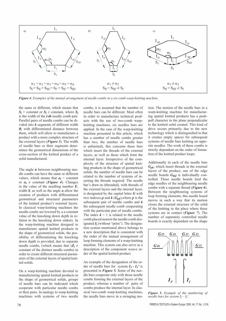
The angle α between neighbouring nee-dle combs can have the same or different values, which means that αi = constant or αi ≠ constant (Figure 4). Changes in the value of the needling number E, width S, as well as the angle α allow the creation of products with differentiated geometrical and structural parameters of the knitted product’s external layers. In classical warp-knitting machines the needle combs are lowered by a a constant value of the knocking down depth in re-lation to the knocking down sinkers. In the warp-knitting machine designed to manufacture spatial knitted products in the shape of geometrical solids, the pos-sibility of differentiating the knocking down depth is provided, due to separate needle combs, (which means that (Zi ≠ constant of the distinct needle combs) in order to create different structural param-eters of the external layers of spatial knit-ted solids.
On a warp-knitting machine devoted to manufacturing spatial knitted products in the shape of geometrical solids, groups of needle bars can be indicated which cooperate with particular needle combs or their pairs. In analogy to warp-knitting machines with systems of two needle
combs, it is assumed that the number of needle bars can be different. Most often in order to manufacture technical prod-ucts with the use of two-comb warp-knitting machines, six needles bars are applied. In the case of the warp-knitting machine presented in this article, which has a number of needle combs greater than two, the number of needle bars is unlimited), this concerns these bars which insert the threads of the external layers, as well as those which form the internal layer. Irrespective of the com-plexity of the structure of spatial knit-ting products in the shape of geometrical solids, the number of needle bars can be related to the number of systems of in-serting the threads required. The needle bar’s draw-in (threaded), with threads of the external layers and the internal layer, is designated by the capital letter G with two indexes p and k (Gpk),where p is the subsequent pair of needle combs and k the subsequent needle comb cooperating with the particular pair of needle combs. The index k = 1 is related to the needle comb placed nearest the needle comb des-ignated Ii (without “prim”). The designa-tion system mentioned above belongs to a new description that is consistent with the order of the mutual arrangement of loop forming elements of a warp-knitting machine. This system can also serve as a description of the component weave or-der of the spatial knitted product.
An example of the designation of the or-der of needle bars for system I1 - I1’ is presented in Figure 5. Some of the nee-dle bars cooperate only with those needle combs forming the external layers of the product, whereas a number of pairs of combs produce the internal layer. In clas-sical two-comb warp-knitting machines, the needle bars move in a swinging mo-
tion. The motion of the needle bars in a warp-knitting machine for manufactur-ing spatial knitted products has a push-pull character in the plane perpendicular to the knitted solid created. This kind of drive occurs primarily due to the new technology which is distinguished in that it creates empty spaces for subsequent systems of needle bars knitting on oppo-site needles. The work of these combs is strictly dependent on the order of forma-tion of the knitted product loops.
Additionally in each of the needle bars Gpk, which insert threads in the external layers of the product, one of the edge needle boards GBZ is individually con-trolled. These needle boards feed the edge needles of the neighbouring needle combs with a separate thread (Figure 6). Between the neighbouring systems of loop forming elements, this needle board moves in such a way that its motion closes the external structure of the solid of the knitting in the place where these systems are in contact (Figure 7). The number of separately controlled needle boards is exactly dependent on the shape
a1 = a2 = a3 = a4 = a5 = a6SI = SII = SIII = SI’ = SII’ = SIII’
a1 ≠ a2 SII = SIII’ ≠ SI
a1 ≠ a2 SII = SIII’ ≠ SI
Figure 4. Examples of the mutual arrangement of needle combs in a six-comb warp-knitting machine.
a) b) c)
Figure 5. Example of the numbering of needle bars for system II – II’.

79FIBRES & TEXTILES in Eastern Europe 2009, Vol. 17, No. 3 (74)
of the figure forming the cross-section of the knitted solid and is related to the number of sides of this figure.
In the warp-knitting machine described in this paper, a new concept of the take-up mechanism and winding device for wale spatial knitting was applied. This concept has hitherto not been used in warp-knitting machines. The take-up de-vicee is built from take-up rolls whose number is equal to the number of sides of the knitted solid. The take-up rolls are arranged along the width of the needle comb, or its segments and act on the ex-ternal layers of the spatial product manu-
factured. An alternative solution for a take-up mechanism can be the pneumatic type, which sucks air from outside, from the side of the needle hooks and acts on the threads of the external and internal layers, causing the creation of a take-up force. However, considering the relative-ly large electrical energy consumption of the sucking generator, this solution is not energy-saving, and is not gener-ally recommended. A storing mechanism cooperates with the take-up device in the form of a dextrorotatory or laevorotatory screw shaft, whose structure prevents the deformation of the spatial knitting prod-uct under manufacture.
Warp-knitting machine with an odd number of needle combs greater than twoThe next structural variant of a warp-knitting machine described in this paper is one with a number of needle combs greater than two, which is designed for manufacturing spatial knitted products in the shape of geometrical solids. It is a machine with an odd number of needle combs (Figure 9).
This machine, similar to warp-knitting machines with an even number of needle combs, can have constant or differing values of such parameters as the needling number E of all the needle combs, the widthe S of particular needle combs and the angle α between neighbouring needle combs (Figure 10).
The needle combs are numbered in the same way as before, which means that by II we understand that this comb is the nearest to the operator standing in front of the machine. Subsequent needle combs have the following designations: III, IIII, etc. whose numbering increases clockwise. In the case of this machine, the needle combs are lifted from II to the last. Taking into account the construction of the warp-knitting machine in order to avoid the possibility of the occurrence of working collisions of neighbouring needle combs, it is not permitted to lift
Figure 6. Concept of individual control of the edge needle bars GBZ in a warp-knitting machine with an even number of needle combs greater than two.
Figure 9. Concept of a tree-comb warp-knitting machine for manu-facturing spatial knitted products.
Figure 7. Working principle of the individ-ually controlled needle bar GBZ.
Figure 8. Take-up devised for a spatial knitted product.

FIBRES & TEXTILES in Eastern Europe 2009, Vol. 17, No. 3 (74)80
particular needle combs at the same time. Lifting needle combs at the same time is possible only in warp-knitting machines with a minimum of five needle combs. For example, in a five - comb knitting machine, the needle comb II can coop-erate with combs IIII or IIV, whereas III cooperates with comb IIV or IV.
In a warp-knitting machine with an odd number of needle combs devoted to manufacturing spatial knitted products in the shape of geometrical solids, we can identify groups of needle bars which co-operate with particular or with all needle combs. The motion of the needle bars also have a push-pull character in rela-tion to the needle combs. The one or several needle bars inserting the threads into the internal layer are equipped with a rotary mechanism hitherto not used in warp-knitting machines, which allows it to cooperate with all needle combs; this can be clearly seen in Figure 11. Similar to the machine with an even number of needle combs, here in each needle bar in-serting threads into the external layers of the product, there are separately control-led edge needle boards, GBZ, which close the external layers of the product’s form. The needle bars which are threaded with threads of the external layers are desig-
nated by indexes p and k (Gpk), where p is the subsequent needle comb, and k is the next needle comb cooperating with the particular needle comb. The index k = 1 is related to the comb which is near-est in relation to needle comb Ii, whereas the needle bars threaded with threads of the internal layer are designated by the capital letter G with index k (Gk), where k is the subsequent needle bar cooper-ating with all needle combs Ii, where k = 1 is related to the comb placed near-est needle comb Ii.
n SummarynA characteristic feature of the new
concept of warp-knitting machine, which is primarily devoted to manu-facturing spatial knitted products, is the existence of more than two nee-dle combs. The new concept includes two types of warp-knitting machines: the first with an even and the second with an odd number of needle combs. The geometrical features of the needle combs determine explicitly the shape of the regular or irregular solids of the spatial product created, as well as the parameters of the knitted structure.
n In contrast to existing warp-knitting machines, the one proposed by us is equipped with a device characterised by the negative feeding of threads with a system of mechanical or pneu-matic compensators, knocking down combs of the holding sinkers and nee-dle bars. Taking into account the pe-culiarity of the technology for manu-facturing spatial products, the needle bars have a push-pull motion, and in the case of a warp-knitting machine with an odd number of needle combs, it has an additional rotary motion. The needle bars are additionally equipped with separate edge needle boards, GBZ, whose purpose is to connect ex-ternal layers of the knitting in the edge
zone. Regarding the motion of the needle combs, for the sinkers’ combs as well as the needle bars, the applica-tion of a hybrid drive (a mechanical-electronic drive) can be considered.
n A novelty in the proposed machine is the structure of the take-up and stor-ing devices. A characteristic feature of the take-up device is a group of rolls which does not deform the structure of the knitted product manufactured. Thanks to the suitable relief (tooth-like) structure of the rolls’ surface, during rotation, the product being manufactured is taken-up and can be stored on a screw shaft or in a machine with a vertical system under it.
n On the basis of the defined structure assumptions of the new concept of multi comb warp-knitting machine, a working model was built. The model was equipped with four needle combs and six needle bars and was used to confirm the correctness of the assump-tions accepted by us, as well as part verification of the possibility of man-ufacturing a spatial knitted product in the shape of a rectangular prism.
References1. Pieklak K., Mikołajczyk Z.; Model of the
Spatial Structure Warp-Knitted 3D Fab-rics, FIBRES & TEXTILES in Eastern Eu-rope, Vol. 16 2008, No. 5 (70), p. 83 – 89.
2. Kopias K.; Technologia dzianin kolumi-enkowych. WNT. Wa-wa 1986, 180 p.
3. Pospelov Е. P.; Dvukhlojjnyjj trikotazh. Moskva 1982, 208 c.
4. Grębowski J.; Tree-layer knitted fabrics (in Polish). Przegląd włókienniczy. No 9, 2000, p. 37 – 38.
5. Zweiwandgewirke – interessante Stoffe für die vielfältigsten Einsatzgebiete. Kettenwirk – Praxis. Nr 2, 1989, p. 55 – 60.
6. Mikołajczyk Z., Pieklak K., Golczyk A., Wiater Z.; Warp-Knitting Machine for Ma-nufacturing Spatial Warp-Knitted Fabrics, Patent Application No. P – 386073, Polish Patent Office, 12.09.2008.
Received 20.08.2008 Reviewed 21.01.2009
a1 = a2 = a3SI = SII = SIII
a1 = a2 = a3 = a4 = a5SI = SII = SIII = SIV = SV
a1 = a2 = a3 = a4 = a5 = a6 = a7SI = SII = SIII = SIV = SV = SVI = SVII
Figure 10. Examples of arrangements of the needle combs of a warp-knitting machine with an odd number of these combs.
a) b) c)
Figure 11. Working principle of the rotary mechanism of needle bars inserting threads of the internal layer.